My Top Five Backyard Multi-Band Wire HF Antennas - Top Five Backyard...My Top Five Backyard...
21
My Top Five Backyard Multi-Band Wire HF Antennas L. B. Cebik, W4RNL 1434 High Mesa Drive Knoxville, TN 37938-4443 e-mail: [email protected] 2004 marks my fifth full decade as a licensed radio amateur. So my offering to FDIM 9 will also be a matter of 5: my personal selection of the top 5 HF wire antennas for the backyard and for multi-band operation. Being a personal selection, there is no reason why your list should not be different from mine. But, along the way, I shall explain why I selected the 5 antenna types that I am including, giving you my views on both their advantages and their limitations. My list is simple and in no particular order. 1. The broadside doublet(s) 2. The dipole-doublet(s) 3. Fanned dipoles 4. The hohpl--horizontally oriented and polarized loop 5. The inverted-L In order to make sense of what we say about each type of antenna, we need a point of reference. Since virtually all of the antennas will be horizontal, the logical baseline to use for comparisons is the resonant 1/2-wavelength dipole. So let's review its characteristics. The 1/2-Wavelength Center-Fed Resonant Dipole The antenna that we loosely call the dipole is actually a 1/2-wavelength center-fed resonant or nearly resonant dipole. We usually construct it from AWG #14 or #12 copper or copperweld wire for the lower HF bands, and we may use bare or insulated wire. Often, we mislabel multi-band doublets as dipoles because the antenna is about 1/2-wavelength at the lowest frequency of operation. But to be strictly correct, that antenna is a dipole only at the lowest frequency of use. Fig. 1 shows the two essential dimensions of a real dipole. Since we tend to feed the dipole with coaxial cable, we are concerned with the antenna length and resonance. In other words, we want a good match between the coax and the antenna feedpoint. However, we also need to be equally if not more concerned with the antenna's height above ground. The old adage, "The higher, the better," arose from the use of wire antennas on the lower HF bands, where we generally could not achieve even a height of 1 wavelength.
-
Upload
phamnguyet -
Category
Documents
-
view
219 -
download
4
Transcript of My Top Five Backyard Multi-Band Wire HF Antennas - Top Five Backyard...My Top Five Backyard...
My Top FiveBackyard Multi-Band Wire HF Antennas
L. B. Cebik, W4RNL1434 High Mesa Drive
Knoxville, TN 37938-4443e-mail: [email protected]
2004 marks my fifth full decade as a licensed radio amateur. So my offering to FDIM 9 will alsobe a matter of 5: my personal selection of the top 5 HF wire antennas for the backyard and for multi-bandoperation. Being a personal selection, there is no reason why your list should not be different from mine.But, along the way, I shall explain why I selected the 5 antenna types that I am including, giving you myviews on both their advantages and their limitations.
My list is simple and in no particular order.1. The broadside doublet(s)2. The dipole-doublet(s)3. Fanned dipoles4. The hohpl--horizontally oriented and polarized loop5. The inverted-L
In order to make sense of what we say about each type of antenna, we need a point of reference.Since virtually all of the antennas will be horizontal, the logical baseline to use for comparisons is theresonant 1/2-wavelength dipole. So let's review its characteristics.
The 1/2-Wavelength Center-Fed Resonant Dipole
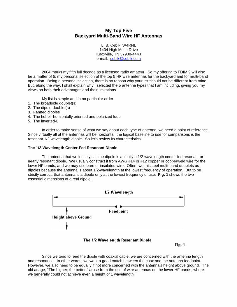
The antenna that we loosely call the dipole is actually a 1/2-wavelength center-fed resonant ornearly resonant dipole. We usually construct it from AWG #14 or #12 copper or copperweld wire for thelower HF bands, and we may use bare or insulated wire. Often, we mislabel multi-band doublets asdipoles because the antenna is about 1/2-wavelength at the lowest frequency of operation. But to bestrictly correct, that antenna is a dipole only at the lowest frequency of use. Fig. 1 shows the twoessential dimensions of a real dipole.
Since we tend to feed the dipole with coaxial cable, we are concerned with the antenna lengthand resonance. In other words, we want a good match between the coax and the antenna feedpoint.However, we also need to be equally if not more concerned with the antenna's height above ground. Theold adage, "The higher, the better," arose from the use of wire antennas on the lower HF bands, wherewe generally could not achieve even a height of 1 wavelength.

Table 1. Approximate Lengths of a Wave in Feet
Band Frequency Length Band Frequency Lengthmeters MHz feet meters MHz feet160 1.8 546 20 14.0 70 80 3.6 273 17 18.1 54 75 3.9 252 15 21.0 47 60 5.37 183 12 24.95 39.5 40 7.0 140.5 10 28 35 30 10.1 97.5
Table 1 serves as a reminder of how long a wavelength is on each of the HF amateur bands. Formost backyard antennas, the average ham is lucky to achieve an antenna height of 1 wavelength on 10meters, while the truly fortunate operator may get his wire to 1 wavelength on 17 or 20 meters.
Every horizontal antenna is subject to essentially the same general phenomena that affecthorizontal dipoles in terms of their height above ground. The lower the antenna as a fraction of awavelength, the lower will be the overall gain and the higher the elevation angle of the radiation. Fig. 2illustrates the principle for a dipole placed at 1/4, 3/8, 1/2, and 1 wavelength above average ground.Unlike vertical monopoles, horizontal wires do not change their gain or elevation angle significantly withchanges in soil quality.
The elevation plots on the right show that the lower we place a dipole, the higher the angle ofradiation, a fact that limits our effective range of communications under normal propagation conditions.The azimuth patterns on the left not only show the reduction of gain with a reduction in height, but as wellthe change in pattern shape. As we reduce the height of a dipole, its figure-8 shape at 1-wavelengthdevolves into a simple oval at a height of 1/4-wavelength. What applies to the dipole will generally (butnot without some exceptions) apply to any horizontal wire antenna relative to its height above ground atthe frequency of operation. When it comes to height, think wavelengths, not feet!
1/2-wavelength resonant center-fed dipoles have many other interesting characteristics, but theones that we have noted will guide us while we explore the top 5 multi-band backyard wire antennas. Weshall also be setting aside our coaxial cable in favor of parallel feedline to an antenna tuner (ATU) or, assome British writers prefer, an antenna system tuning unit (ASTU). Consider the ATU to be a lifetimeinvestment.

1. The Broadside Doublet(s): The broadside doublet is a simple multi-band doublet with a 4:1 frequencyrange for the desired characteristic. Fig. 3 shows the general outline.
In principle, the doublet is physically no different from a dipole. However, electrically, it issignificantly different. First, we feed it with parallel transmission line to an antenna tuner, because thefeedpoint impedance varies greatly as we change operating frequencies from one band to the next.Second, we select the length so that the antenna will show a bi-directional pattern broadside to the wireon all of the bands included. Note that the length makes the antenna an extended double Zepp at thehighest frequency. With an antenna tuner, the antenna will operate above its highest included frequency,but the pattern will break up into multiple lobes.
Table 2 provides the most convenient lengths and the bands included.
Table 2. Broadside Doublet Lengths and Amateur Band Coverage
Length (feet) Bands covered44' 10, 12, 15, 17, 20, 30, 40 meters66' 15, 17, 20, 30, 40, 60 meters88' 20, 30, 40, 60, 80 meters
The chief advantage of the broadside doublet is that you always know the directions of yourradiation or your most sensitive reception. A second advantage is the antenna's simplicity for a 4:1frequency range with the bi-directional characteristic. A third advantage, which we shall note shortly, isthe flexibility of the antenna in forming wire arrays having different characteristics.
With every set of advantages come one or more disadvantages. First, the antenna requires awide-range ATU, since the impedance varies greatly from band to band. Since the exact values that willappear at the tuner terminals will vary with both the antenna height and the length and characteristicimpedance of the parallel transmission line, I shall not provide specific numbers.
Second, the gain goes down with frequency. The broadside doublet has its highest gain at thehighest frequency. The gain drops a bit with each move to a lower band, while the pattern broadens.Fig. 4 shows the patterns overlapped in free-space models. However, remember that as we go down infrequency, the antenna will have a height that is a smaller fraction of a wavelength. Hence--like thedipole--we can expect a further reduction in gain and a more significant increase in the elevation angle ofmaximum radiation. Hence, the higher you can place the antenna, the better will be its performance.

Part of the flexibility of the broadside doublet stems from the ease of covering the full horizon byadding only one more support. See Fig. 5.
We can easily form a triangle of doublets. The triangle need not be perfect, so you can adjust itto aim more exactly at your favorite communications targets. With only a bit of end space (about 10% of

the wire length), the inert wires will not materially affect the operation of the one in use. The only cautionthat you need to observe is to keep the feedline lengths identical. This caution applies whether you use afancy switching box at the center of the array or whether you bring three separate and well-spaced linesto the shack entry point and do your switching indoors. Equal line lengths will mean that you do not haveto do major retuning when switching from one antenna to the other. Hence, you can easily determine themost effective antenna for an incoming signal just by switching through the 3 antennas.
Note that the triangle refers to either doublets or lazy-H antennas. That is part of the flexibility ofthe broadside doublet system. We can make lazy-H arrays using any of the listed element lengths andcover the same set of bands--but with more gain. Fig. 6 the outlines of a lazy-H.
The lazy-H is simply 2 broadside doublets fed in phase. We need the center main feed point toensure that the lines to both wires are the same length and therefore give us the same current magnitudeand phase angle at both element feedpoints. So PL1 and PL2 are 1/2 of PL. The total length of thephase line assembly can be longer than the spacing, but for most installations, they are the same. Theideal spacing is 1/2 of L, the element length. Hence, the spacing is 5/8-wavelength at the frequencywhere the element is 1.25 wavelengths. This spacing provides maximum gain. You can reduce thespacing somewhat, but every reduction reduces the gain on all bands.
The ideal lazy-H will net you almost 3-dB gain on the highest bands. There will be a slightreduction for the lowest bands, since the spacing will no longer be optimal. As well, the lower wire getscloser to the ground as a fraction of a wavelength when we reduce the frequency. Fig. 7 shows theoverlaid free-space patterns to give you a basic idea of what happens to shape and strength, butremember to modify your expectations depending upon the height that you place the antenna. Gettingthe lowest wire at least 1/2-wavelength above ground is best, although lower heights for that wire willwork. However, if that wire will be under 1/4-wavelength above ground, you may be better off with asimple broadside doublet at the upper level. It will give you a lower radiation angle than the pair of wires.As a side note, in any set of in-phase fed antennas--whether doublets, Yagis, or whatever--the effective

height of the combination will be a point about 2/3 the distance between the lowest and the highestantennas. Of course, we can make a triangle of lazy-Hs, just as we can for the basic doublet.
There is a second multi-band array that we can make from the broadside doublet: an 8JK. SeeFig. 8 for the outline. Developed by John Kraus, W8JK, in the 1930s, the antenna has undergone manyvariations. The versions shown here is designed for a 3:1 frequency range. It uses the broadside doubletlengths for the highest frequency, along with a total phase-line length that is 1/2 of the element length, L.However, note that when we create this end-fire array, we give one (and only one) of the phase linesections a half twist.
The specific dimensions we have chosen from W8JK's work are ones that give us an interestingpattern of gain, as shown in the free-space patterns of Fig. 9. The free-space gains are about equal onall bands. Indeed, the only factor that limits our frequency coverage is a very low impedance below thelisted frequency limit.

Of course, over ground, the gain will decrease as we lower the frequency, since the array will belower as a fraction of a wavelength. Within the included bands, the gain will be much more equal fromband to band than with the lazy-H. However, the peak gain will not be as high at the highest coveredbands.
We may summarize the array dimensions in a simple table (Table 3). Remember that since weare using parallel feedline and an antenna tuner, broadside doublet lengths are not finicky. However, inthe arrays, strive for equal lengths for each element.
Table 3. Lazy-H and 8JK Dimensions
Element Length Phase-Line Bands covered (meters)(L, feet) Length (PL, feet) Lazy-H 8JK44' 22' 10 - 40 10 - 3066' 33' 15 - 60 15 - 4088' 44' 20 - 80 20 - 60
2. The Dipole-Doublet(s): The dipole-doublets differ from the broadside doublets in two respects. First,rather than determining their length based on the highest frequency of use, we determine it based on thelowest frequency. In most cases, the doublet is a 1/2-wavelength dipole (approximately) at the lowestfrequency. (Even the G5RV doublet is a dipole on 60 meters.) Again, since we shall use parallel feedlineand an ATU, we do not have to be finicky in setting the exact length.
Second, we do not give any preliminary thought to the lobe structure of the radiation pattern whenwe set up a dipole-doublet. Usually, we know that the pattern is bi-directional at the lowest frequency.However, we often do not think about the pattern above that frequency. As we shall see, the bi-directional patterns holds true until the antenna length as measured in wavelengths is greater than about1.25. However, for many users, the patterns for the higher bands are mysterious.
To get us started, Fig. 10 outlines the basic dipole-doublet. It chief advantages are simplicity andthe ability to cover all of the HF bands above the frequency for which the wire is a 1/2-wavelength dipole.Hence, the preferred lengths are usually about 260' for 160-meter coverage, 135' for 80-meter coverage,

and 67' for coverage down to 40 meters. As noted, the G5RV 102' doublet manages to be a dipole at 60meters. The 67' length will load on 60 meters, and the G5RV will load on 80 meters. In each case, thewire is about 1/3-wavelength, close to the limit for a center-fed wire. Below that length, the resistive partof the impedance goes too low and the capacitive reactance goes too high for most parallel line and tunercombinations to handle.
To start the process of becoming familiar with the typical patterns of a dipole doublet, examineFig. 11. The dipole-doublet's length in feet matters less than how long the doublet is at a given operatingfrequency in terms of half-wavelengths. When the length is close to an even number of half-wavelengths,we have as many lobes as we do half-wavelengths. The strongest lobe moves farther from a broadsidedirection as we increase frequency. As well, the beamwidth of the strongest lobe becomes narrower.Because the ham-band operating frequencies do not result in exact multiples of a half-wavelength, thelobe strengths will vary. But the count remains true.

If we operate the same antenna at odd multiples of a half-wavelength, we obtain patternscomposed of both emerging lobes and diminishing lobes. So the number of lobes is the sum of the oldeven number of half-wavelengths and the new even number of half wavelengths. In other words, wehave twice the number of lobes as we do the length in half-wavelengths. See Fig. 12. Again, becausethe nearest ham-band frequencies are not precisely the number of half-wavelengths listed, we find someof the lobes weaker than others. However, the count remains true.
The patterns would change if we used a 102' or a 67' doublet when referenced to specificfrequencies. However, relative to the frequency at which the doublet is 1/2-wavelength long, the patternswould re-emerge as shown as the antenna approaches lengths of 1 wavelength, 3/2 wavelengths, 2wavelengths, etc. In addition, the dipole-doublet is subject to the same rules relating antenna height as afraction of a wavelength to radiation elevation angles that we discovered for the resonant dipole.
If we understand the pattern development of a dipole-doublet, we can successfully use it withoutdisappointments. The feedpoint impedance will vary over a wide range. In fact, it will be very highwhenever the doublet is a multiple of a full wavelength. Hence, many users prefer 600-800-Ohm ladderline so that the line is an intermediate impedance between the highest and lowest values encountered.
I like the old dipole-doublets for their simplicity and their long tradition of successful use. Theyare also flexible. We can set up a triangle of them, but the complex patterns may not give us the fullhorizon coverage of the triangle of broadside doublets. There is even an old (1930s) trick that we canuse with the dipole-doublet: the center-support Y. Fig. 13 shows the general outlines. The sketch shows67' legs, comparable to a 135' doublet. However, you can use 50' or 35' legs with reduced low bandcoverage.
The Y-doublet's special feature is the use of a non-conductive center support (which may be nosupport at all if you can devise a way to hang the center freely). Either by spacing wires from a centerpole or using triangular spacers, we bring down 3 wires, one from the inner end of each leg. The down-wires form the parallel transmission line. At the shack entry point, we set up a switching system to selectthe pair of wires to form the transmission line for the active doublet. In most cases, it will not matterwhether the third wire simply floats or is grounded: it is centered between the 2 active wires and hasalmost no current on it.
The Y-doublets form 120-degree angles. This angle makes almost no difference in the patternrelative to a linear doublet. There will be some differences in the patterns on the upper bands comparedto those we saw for the linear doublet. Nevertheless, you will use an A-B-C switch to determine whichpair of legs provides strongest signal. In order to make radical re-tuning unnecessary, it is important tokeep the transmission line wires equally spaced in a triangle all the way to the switch at the shack entrypoint. The Y-doublet is one way to overcome some of the limitations of the dipole-doublet's multiple lobeson the upper HF bands.
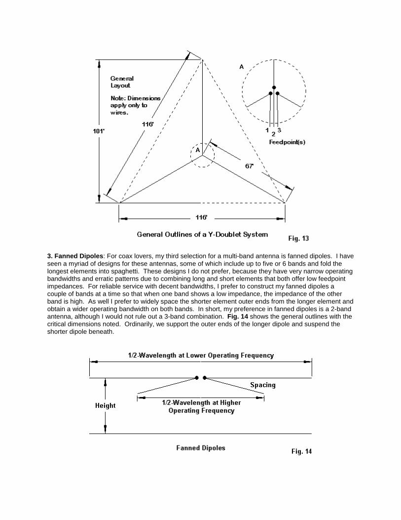
3. Fanned Dipoles: For coax lovers, my third selection for a multi-band antenna is fanned dipoles. I haveseen a myriad of designs for these antennas, some of which include up to five or 6 bands and fold thelongest elements into spaghetti. These designs I do not prefer, because they have very narrow operatingbandwidths and erratic patterns due to combining long and short elements that both offer low feedpointimpedances. For reliable service with decent bandwidths, I prefer to construct my fanned dipoles acouple of bands at a time so that when one band shows a low impedance, the impedance of the otherband is high. As well I prefer to widely space the shorter element outer ends from the longer element andobtain a wider operating bandwidth on both bands. In short, my preference in fanned dipoles is a 2-bandantenna, although I would not rule out a 3-band combination. Fig. 14 shows the general outlines with thecritical dimensions noted. Ordinarily, we support the outer ends of the longer dipole and suspend theshorter dipole beneath.

Let's get a handhold on the properties of fanned dipoles with a simple 80-40-meter combination.We shall look at two versions of the same antenna. One will droop the 40-meter dipole 10' below the 80-meter dipole. The other design will place the 40-meter outer ends 1' below the low-band dipole. The 80-meter dipole is set for 3.6 MHz, while the 40-meter dipole is set for 7.1 MHz. Table 4 gives us thedimensions and the performance of the array on each band with the 80-meter dipole 50' above averageground.
Table 4. Fanned 80-40-Meter Dipole Dimensions and Modeled Performance at 50'
Frequency Length Gain TO Angle Feedpoint ZMHz feet dBi degrees R+/-jX Ohms
Wide-Spaced Version3.6 130.4 6.63 86 61 - j 17.1 67.0 4.82 44 54 - j 0
Close-Spaced Version3.6 130.4 6.80 88 61 + j 27.1 75.3 4.85 40 58 + j 2
Although there is no significant difference in performance at the two design frequencies betweenthe wide and the close dipoles, we certainly can see a difference in the length of the 40-meter dipole.The wide-spaced version shows a length that approximates the length of an independent 40-meter dipole.However, the close-spaced version requires a much longer 40-meter element. Remember that the closespacing is still 1', which is wider than some published and commercial designs.
Fig. 15 shows the elevation patterns for the two bands. Like all horizontal antennas at lowheights, neither pattern is ideal. The antenna on 80 meters is below 0.2 wavelength, and it only achieves0.36 wavelength on 40 meters. As with all of the horizontal wire antennas, it could benefit from additionalheight.
We cannot see much difference in performance between the two versions of the antenna on thedesign frequencies, but we did note the 40-meter dimension change to obtain that performance. The 80-meter length did not change as we altered the spacing of the 40-meter ends from the 80-meter wire.Obviously, in a fanned dipole arrangement, we expect the shorter wire to undergo more change than thelonger one. The question is how we can sample the long-wire stability and the short-wire variability.
One way to see the difference is to examine the 50-Ohm SWR curves for the two versions offanned dipoles. Since the 80-meter wire remained stable, we would expect the SWR (as a measure ofchanges in resistance and reactance) also to remain stable. Fig. 16 tells the story.

The 40-meter 50-Ohm curves stands in stark contrast, as revealed by Fig. 17. The wide-spacedversion of the antenna covers over 2/3 of the band. The close-spaced version barely handles 100 kHz.While the narrower bandwidth may be satisfactory for some operational needs, it also indicates thatpruning the close-spaced 40-meter dipole to length is likely to be a somewhat ticklish task.
To understand why closing the space between the dipoles shrinks the usable passband of thehigher-frequency dipole, we should make at least one more probe into the operation of the antennas.Modeling software gives us a look at the current distribution along the dipoles. Let's compare the currentson both versions of the array.
Fig. 18 shows in the curves on the left the relative currents on the wires during 40-meteroperation. Notice that, despite the high impedance of the 80-meter dipole, there remains a low butsignificant current on the wire. Even with wide spacing and a predominance of current on the 40-meterwire, the two dipoles do not achieve the kind of independence that casual fanned-dipole theory suggests.When we move to the right and examine the closed-spaced version of the array, we see a considerableincrease of current on the 80-meter dipole. The closer that we space the two dipoles, the higher thecurrent on the longer one. The higher the current that we find on the longer dipole, the narrower will bethe operating passband of the shorter dipole and the more painful will be the job of setting its proper

length. As well, we are likely to find that a set of lengths that is right for one antenna height is not right fora different height.
Fanned dipoles have served me well over the years, but only when I restricted the number ofbands covered and when I separated the shorter dipole ends as far as feasible from the longer wire. Aswell, a 2:1 frequency ratio has tended to yield the most successful antennas with the widest operatingbandwidth. Still, do not count the fanned dipole out when it comes to flexibility. I once tied a 10-metervertical dipole to a horizontal 15-meter dipole with good success. One might even use close spacing (andpatient pruning) to set up a combination for 12 and 17 meters or for 17 and 30 meters, where operatingbandwidth is less of a question. However, I likely would steer away from combinations like 40 and 15meters or 30 and 12 meters.
4. The HOHPL--Horizontally Oriented and Polarized Loop: The horizontal loop is subject to severalmisconceptions. Two of the most popular are that 1. The longer I make the loop, the more gain I get, and2. The loop gives me omni-directional coverage on all of the HF bands. Basically, if you want more gain,then place the antenna higher. Moreover, even if you create a perfect circle, your pattern will not becircular on almost any band. Nevertheless, the loop is a good multi-band antenna easily fed with paralleltransmission line and an ATU.
Fig. 19 shows the outlines of te two most popular shapes for a horizontal loop: the square andthe triangle. Almost any other closed shape--regular or irregular--is possible. Most polygons with more

sides tend to act like squares, so the contrast between the square and the triangle become good guideson what to expect from a loop strung along the perimeter trees in an average yard. Each loop shows 2(different) feedpoints: a mid-side location and a corner location. These two points tend to coincide withthe most convenient installation points from which to run the parallel feedline from the antenna to theATU. You can select an alternative position and nothing evil will happen. However, the patterns will notbe as regular as the ones that we shall use for demonstration purposes.
I prefer to use a 2-wavelength loop at the lowest frequency of operation. In fact, ourdemonstration loops will be 560' loops with 80 meters as the lowest band. Loops have a peculiarity. Ifwe make them about 0.75-wavelength or smaller, they tend to radiate off the loop edge. If we make themclose to 2 wavelengths or larger, they also tend to radiate off the edge. However, if we make the loop 1-wavelength--or thereabouts--at the frequency of operation, then it radiates broadside to the loop. Hence,a horizontal 1-wavelength loop becomes a good NVIS antenna, as our 80-meter 2-wavelength loop wouldbecome on 160 meters. Incidentally, we shall place the demonstration loop 70' above ground simply forthe exercise. 70' is about 1/4-wavelength on 80 meters but 2 wavelengths on 10 meters.
The phenomena of changing planes of radiation as we enlarge a loop will explain why my list ofthe top five multi-band antennas does not include any vertically oriented loops. Lets start with a 1-wavelength loop. It does fine on the band for which it is cut. However, by the time we double thefrequency of operation, the loop is radiating off the edge, producing mostly high-angle radiation. Suchloops will make contacts, but not as well as a horizontal loop.
On the lowest band of operations, we do not choose the loop for gain. As shown in Fig. 20, thereis very little gain difference between the loop and a resonant dipole at the same height. The mid-side-fedsquare loop used to generate the loop part of the pattern is not even significantly more omni-directionalthan the dipole pattern. However, at their lowest operating frequencies, loops tend to show a lowerradiation angle than a low dipole. In the case that uses antennas at the 70' level, the dipole's take-offangle is 58 degrees, but the loop's angle is between 44 and 50 degrees, depending upon the loop shapeand the feedpoint position. This advantage is useful at the lowest operating frequency, but it does not lastas we increase frequency. By the time we double the operating frequency, the take-off angle for loopstracks well with the take-off angles for doublets at the same height.
Loop antenna shape and the position of the feedpoint do make a difference to the antenna'spattern and performance. Fig. 21 shows the 3.6-MHz azimuth patterns for the two loops (square andtriangular) with both corner and mid-side feedpoints. The notation FP on the plots shows the relativeposition of the feedpoint to the development of the plot. The triangular plots are--relative to the feedpointposition--more alike than the two plots for the square loop. In both triangle cases, the direction of themain lobe crosses the feedpoint and a point in the middle of the opposite side. The main difference is areverse in the slight gain advantage. For the corner-fed triangle, maximum gain is away from thefeedpoint, while in the mid-side version, gain is more toward the feedpoint. The squares, however, showa more distinct pattern difference, depending upon the feedpoint position. The corner feedpoint producesa nearly circular pattern, while the mid-side feedpoint yields a 4-lobe pattern.

Although there are no major differences in gain, Table 5 presents the modeled maximum gainvalues and take-off angles for the 4 loops on various HF bands, using our basic 560' loops at 70' aboveaverage ground. Because we shall use an ATU, the feedpoint impedance data is not especially usefulhere.
Table 5. Modeled Performance of 560' Horizontal Loops at 70' on Selected Amateur Bands
Note: Performance shown as Maximum Gain (dBi)/TO Angle (degrees).
Loop Square Square Triangle TriangleFrequency Corner-Fed Side-Fed Corner-Fed Side-Fed3.6 5.9/50 6.7/44 7.1/48 6.4/457.0 10.6/27 9.9/26 9.7/28 10.4/2814.0 12.9/12 11.6/12 13.9/13 11.2/1321.0 14.6/ 9 14.3/ 9 13.4/ 9 12.4/ 928.0 15.1/ 7 13.6/ 7 14.1/ 7 11.0/ 7

I have inserted Fig. 22 immediately following the chart of modeled gain values so that you will notmake too hasty a decision on which loop to select. It shows the patterns on 40 through 10 meters thatproduce the gain figures in the chart, at least for the square loops. Above 40 meters, we discoverpatterns with many lobes. The higher we go in frequency, the more lobes we encounter and the morevariable we find the lobe strength. As a general rule of thumb with simple wire antennas, the higher thegain of a lobe, the narrower its beam width. So we obtain maximum gain only over a small targetcommunications arc. In these patterns, dots serve to locate the feedpoint position on the loop relative tothe pattern.
Fig. 23 provides the corresponding patterns for the triangular loop. On 80 through 20 meters, theloop produces patterns that have a distinct axis on the line formed by the feedpoint and the opposing loopposition. Above 20 meters, the patterns become as individual as snowflakes, each very regular butdistinct from the other patterns. When we combine the patterns of the three plot figures together, wemay finally come to understand that on the upper HF bands, horizontal loops do not produce patterns thatare more omni-directional than doublets. The patterns are simply different in the relative positions of thelobes and nulls. As well, the chart shows that on the upper HF bands, the radiation angles are similar tothose of simple wire doublets.
So why choose a horizontal loop as one's multi-band wire antenna? One good reason is theimprovement in radiation angle on the lowest frequencies of operation. A second good reason is becauseyou have the perimeter supports already growing in your yard. A third reason is because closed loopstend to be less prone to the build up of static charge relative to doublets with unterminated ends. (Thisfeature does not guarantee immunity from all noise sources. Nor does it guarantee immunity from thehazards or lightning and associated thunderstorm dangers.)
A fourth reason is because large closed loops tend to have less high-angle radiation. What maybe more important, this fact means less receiving sensitivity to high-angle sensitivity to QRM and QRNfrom closer-in sources. Fig. 24 compares the 21-MHz elevation patterns for a simple 135' linear doubletand a 560' triangular loop with its feedpoint in the middle of one side. Although the exact shapes of the15-meter elevation patterns will vary from one loop to another in the set that we have been examining,they all share the general property of having less high-angle radiation.
The loop has several advantages that recommend it as a multi-band antenna, if you can live withthe upper band patterns, if you have room for the array, if you can find the wire and the supports, and ifyou are prepared for the maintenance that a long stretch of wire requires. All those "ifs," of course,represent the disadvantages of the horizontal loop.
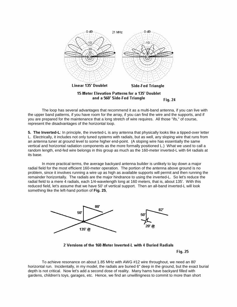
5. The Inverted-L: In principle, the inverted-L is any antenna that physically looks like a tipped-over letterL. Electrically, it includes not only tuned systems with radials, but as well, any sloping wire that runs froman antenna tuner at ground level to some higher end-point. (A sloping wire has essentially the samevertical and horizontal radiation components as the more formally positioned L.) What we used to call arandom length, end-fed wire belongs in this group as much as the 160-meter inverted-L with 64 radials atits base.
In more practical terms, the average backyard antenna builder is unlikely to lay down a majorradial field for the most efficient 160-meter operation. The portion of the antenna above ground is noproblem, since it involves running a wire up as high as available supports will permit and then running theremainder horizontally. The radials are the major hindrance to using the inverted-L. So let's reduce theradial field to a mere 4 radials, each 1/4-wavelength long at 160 meters, that is, about 135'. With thisreduced field, let's assume that we have 50' of vertical support. Then an all-band inverted-L will looksomething like the left-hand portion of Fig. 25,
To achieve resonance on about 1.85 MHz with AWG #12 wire throughout, we need an 80'horizontal run. Incidentally, in my model, the radials are buried 6" deep in the ground, but the exact burialdepth is not critical. Now let's add a second dose of reality. Many hams have backyard filled withgardens, children's toys, garages, etc. Hence, we find an unwillingness to commit to more than short
radials. So the right-hand side of Fig. 25 shows the same set-up with 4 20' radials. The horizontalsection of the antenna needed a 2' extension to restore resonance at 1.85 MHz. Now let's compareperformance (Table 6).
Table 6. Inverted-L Performance with Full and Short Radial Systems
Antenna 135' Radials 20' RadialsFrequency Gain TO Angle Feed Z Gain TO Angle Feed ZMHz dBi degrees R+/-jX Ohms dBi degrees R+/-jX Ohms1.85 -2.2 29 38 - j 2 -2.6 29 47 + j 23.6 3.5 84 4500 + j1750 3.8 84 5200 - j1507.0 4.0 35 700 + j 750 4.0 35 900 + j 80014.0 5.2 22 300 + j 300 5.3 23 350 + j 35021.0 6.0 13 200 + j 80 5.8 13 250 + j 20028.0 7.7 10 200 - j 100 7.5 10 200 + j 30
In practical terms, we find a significant performance difference only on 160 meters. The #12inverted-L is under ideal conditions about 2 dB less effective than a full size vertical monopole. When weshorten the radials, we lose another half-dB of gain. Otherwise, the two systems are roughly equivalentfor all-band operation. The short radials and longer horizontal section of the smaller system do raise theimpedance values, but if a tuner will handle one set, it will also handle the other.
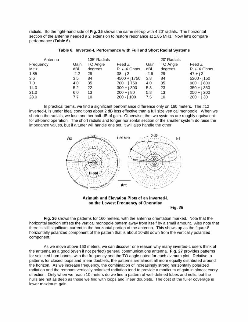
Fig. 26 shows the patterns for 160 meters, with the antenna orientation marked. Note that thehorizontal section offsets the vertical monopole pattern away from itself by a small amount. Also note thatthere is still significant current in the horizontal portion of the antenna. This shows up as the figure-8horizontally polarized component of the pattern that is about 10-dB down from the vertically polarizedcomponent.
As we move above 160 meters, we can discover one reason why many inverted-L users think ofthe antenna as a good (even if not perfect) general communications antenna. Fig. 27 provides patternsfor selected ham bands, with the frequency and the TO angle noted for each azimuth plot. Relative topatterns for closed loops and linear doublets, the patterns are almost all more equally distributed aroundthe horizon. As we increase frequency, the combination of increasingly strong horizontally polarizedradiation and the remnant vertically polarized radiation tend to provide a modicum of gain in almost everydirection. Only when we reach 10 meters do we find a pattern of well-defined lobes and nulls, but thenulls are not as deep as those we find with loops and linear doublets. The cost of the fuller coverage islower maximum gain.

There is no significant difference between the pattern shapes for the L with a full radial field or theL with short radials. Remember that these patterns apply to an inverted-L with a 50' vertical section. Ifyou bend the L at a lower height, the TO angles for 80 through 10 meters will rise, and the gain and exactpattern shape may change. However, let's consider one more version in which the user does not laydown a symmetrical (or thereabouts) radial field. The one thing necessary to the use of the inverted-L isa good RF ground, so this user lays down 1 buried radial about 20' long. See Fig. 28.
Table 7. Inverted-L Performance with One Buried 20' Radial
Frequency Gain TO Angle Feed ZMHz dBi degrees R+/-jX Ohms1.85 -5.7 29 82 + j 173.6 3.7 88 5300 - j1007.0 3.5 35 990 + j 80014.0 4.4 22 450 + j 35021.0 4.6 13 300 + j 15028.0 6.0 10 250 + j 10

As Table 7 shows, performance does diminish relative to the other systems. However, only on160 meters, where we lose another 3dB of gain, is the result unworkable. On the other bands, we obtainusable performance. For emergency and field operations, the 1-radial inverted-L may be usable from 80through 10 meters. However, for home use, we should strive to add as many radials--shaped howeverthe ground will permit--as we can, even if we only add one every few months. The usual safetyprecautions apply to radials: get them below ground where playing children, gardening spouses, andseeing-eye lawn mowers cannot reach them. If you use a tree to support the feed-end of the antenna, besure to space the vertical well away from the tree trunk. In addition, make sure that no one can touch theantenna or its feedpoint during operation.
You will note that the 80-meter impedance is very high, higher than most antenna tuners canhandle. For this reason, many inverted-L users prefer to use wire lengths longer or shorter than the 130'length that I used in this demonstration. A 3/8-wavelength inverted-L (about 100' including both thevertical and horizontal sections) will move the very high impedance frequency to the 30-meter band.Pattern shapes will change, but the general properties of the inverted-L will remain: good (but not great)bulbous patterns for general communications in almost every direction.
One final question: where do I place the antenna tuner? The answer is simple: at the antennafeedpoint. This position is standard in the field, where we usually terminate the antenna at the operatingposition with a manual antenna tuner. For this antenna, we actually need a single-ended network tuner.At home, the inverted-L is an ideal application for one of the weather-protected automatic tuners (usingprecautionary additional weather shielding) with the case or ground lead connected to the radial side ofthe system. The advantages of this type of system are obvious: automatic (or semi-automatic) tune-upwith a coaxial cable from the antenna feedpoint to the rig. The disadvantages are the initial expense ofthe automatic tuner and periodic preventive maintenance.
Final Notes: We have now surveyed my personal five favorite multi-band wire backyard antennas. Thereare others that I might have included. In fact, I thought of some others, but gradually discovered that theywere mostly variations of the ones that I included. For example, there are some sloping and bent wireantennas calling for either measured or random-length "counterpoises." However, they are simplevariations on the inverted-L. Linear dipole-doublets have inverted-Vee variations.
I have omitted antennas using traps, simply because traps require maintenance and represent anadvanced project for most folks who roll their own. All of the antennas I chose involve only wire andfeedline plus, of course, the antenna tuner. For all but the inverted-L (and possible the fanned dipoles),we need a balanced tuner that will handle a very wide range of resistance and reactance at its terminalswith the highest possible efficiency. Although there are a few balanced network and Z-match tunersavailable, most hams still use single-ended network tuners with a 4:1 balun at the terminals.Unfortunately, not all 4:1 tuner baluns are made equal, and many show high losses in the presence ofeither high reactance values or very low impedances that may occur as the feedpoint impedance istransformed along the parallel feedline.
There is an alternative system for using the single-ended network tuner in the manner in which itis most efficient: as a single-ended network. Fig. 29 shows the essentials. At the shack entry point, weterminate the parallel feedline with a 1:1 balun. Actually, the unit is a simple choke in preference to atransmission-line transformer that prefers a minimum of reactance. A W2DU-type choke composed ofabout 50 ferrite beads around a length of coax tends to work quite well in this application. We run a leadto an earth ground from the coax braid right at the coax side of the choke itself. This measure tends toattenuate any remnant RF that might get onto equipment cases or into circuitry. Make the coax run asshort as possible using the lowest-loss coax that you can obtain, since there will still be a considerableSWR on the line to the tuner. However, this line goes directly to the coax connector on the tuner outputside for single-ended processing. The system is not perfect and does have small losses. However, inmost cases, it tends to clear the shack of unwanted stray RF from indoor parallel feedlines, and it doesallow the single-ended tuner to effect a reasonably efficient match with the remainder of the antenna
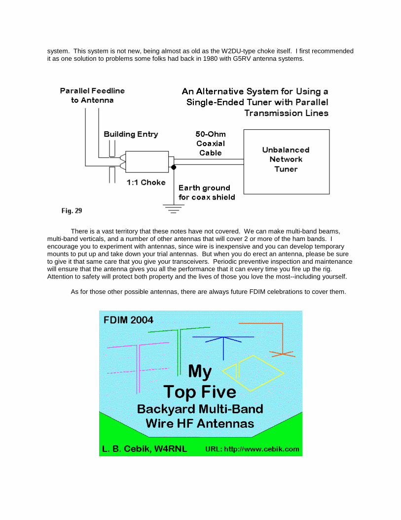
system. This system is not new, being almost as old as the W2DU-type choke itself. I first recommendedit as one solution to problems some folks had back in 1980 with G5RV antenna systems.
There is a vast territory that these notes have not covered. We can make multi-band beams,multi-band verticals, and a number of other antennas that will cover 2 or more of the ham bands. Iencourage you to experiment with antennas, since wire is inexpensive and you can develop temporarymounts to put up and take down your trial antennas. But when you do erect an antenna, please be sureto give it that same care that you give your transceivers. Periodic preventive inspection and maintenancewill ensure that the antenna gives you all the performance that it can every time you fire up the rig.Attention to safety will protect both property and the lives of those you love the most--including yourself.
As for those other possible antennas, there are always future FDIM celebrations to cover them.