MY PROJECT OF SURPAC - Copy - Copy.docx
45
INDIAN SCHOOL OF MINES DHANABD PROJECT TITLE:- Ultimate Pit Design of ore body by using of exploration bore-hole data of a mine by application of SURPAC. MENTORED BY:- KASHINATH PAL ASST. PROFFESOR, DEPARTMENT OF MINING ENGINEERING, INDIAN SCHOOL OF MINES,DHANBAD (Signature with date) PREPARED BY:- BISHAL Admn. No: - 2010JE0501 9TH SEMESTER, DUAL DEGREE (MINING ENGINEERING)
-
Upload
bishaltiwari -
Category
Documents
-
view
141 -
download
20
Transcript of MY PROJECT OF SURPAC - Copy - Copy.docx

INDIAN SCHOOL OF MINES DHANABD
PROJECT TITLE:- Ultimate Pit Design of ore body by using of exploration bore-hole data of a mine by application of SURPAC.
MENTORED BY:-
KASHINATH PALASST. PROFFESOR, DEPARTMENT OF MINING ENGINEERING,INDIAN SCHOOL OF MINES,DHANBAD (Signature with date)
PREPARED BY:- BISHAL Admn. No: - 2010JE0501 9TH SEMESTER, DUAL DEGREE (MINING ENGINEERING)
+
CONTENT

Acknowledgement Objective Scope of work Literature Review Methodology Work to be done References

ACKNOWLEDGEMENT
I wish to record my indebtedness and gratitude to my mentor K.Pal, Assistant Professor,Department of Mining Engineering, Indian School of Mines, Dhanbad for their constant guidance untiring encouragement and suggestion in conducting out this project work. It is indeed a great pleasure to work under them. I am especially thankful to ISM library, department lab and for extending their help in my project work.
DATE:-25/11/2014 BISHAL
INTRODUCTION
OBJECTIVE :-
Ultimate Pit Design of ore body by using of exploration bore-hole data of a mine by application of SURPAC.
SCOPE OF WORK:- Calculation of correct volume of material removed from an area between certain
periods as required. Reserve estimation with a view to optimize and conserve mineral resource Multi elemental grade calculation, grade control and prediction
LITERATURE REVIEW Introduction to SURPAC:-
Surpac is the world’s most popular geology and mine planning software, supporting open pit and underground operations and exploration projects in more than 110 countries. The software delivers efficiency and accuracy through ease-of-use, powerful 3D graphics and workflow automation that can be aligned to company-specific processes and data flows. Surpac addresses all the requirements of geologists, surveyors, and mining engineers in the resource sector and is flexible enough to be suitable for every commodity, ore body and mining method. Its multilingual capabilities allow global companies to support a common solution across their operations.
SURPAC BENEFITS :-
Comprehensive tools include: drill hole data management, geological modelling, block modelling, geostatistics, mine design, mine planning, resource estimation, and more.
Increased efficiencies within teams result from better sharing of data, skills and project knowledge.
All tasks in Surpac can be automated and aligned to company-specific processes and data flows.
Software ease-of-use ensures staff develops an understanding of the system and of project data quickly.
Surpac is modular and easily customised. Surpac reduces data duplication by connecting to relational databases and interfacing
with common file formats from GIS, CAD and other systems. Integrated production scheduling with Gemcom MineSched. Integrated production scheduling with Gemcom MineSched.
REQUIREMENTS TO RUN SURPAC:-
SURPAC FUNCIONALITY:-
GEOLOGICAL DATABASE CREATING A GEOLOGICAL DATABASE DISPLAYING DRILLHOLES ADDING STYLES TO GEOLOGICAL PATTERNS CREATION OF DRILLHOLE LAYOUT CREATING SURFACE DTM COMPOSITING CREATING SECTIONS DIGITISING SECTIONS
SOLID MODELLING TRIANGULATION VALIDATION MAKING SOLID
BLOCK MODEL CREATING A BLOCK MODEL DISPLAYING A BLOCK MODEL ADDING CONSTRAINT TO BLOCK MODEL ADDING ATTRIBUTES TO BLOCK MODEL BLOCK MODEL REPORT
ULTIMATE PIT DESIGNING DIVIDE THE BLOCK MODEL IN DIFFERENT LEVELS

BOTTOM LAYER PAN IS CREATED BENCH IS CREATED EXPAND THE BENCH VERTICALLY AND LATERALLY
Basic procedures:--
Surpac GUI String Concept DTM Concept&Application-Conturing Survey Database Geological Database&its application Solid Model Block Model&Slice Plan Pit Desin
SURPAC GUI:-
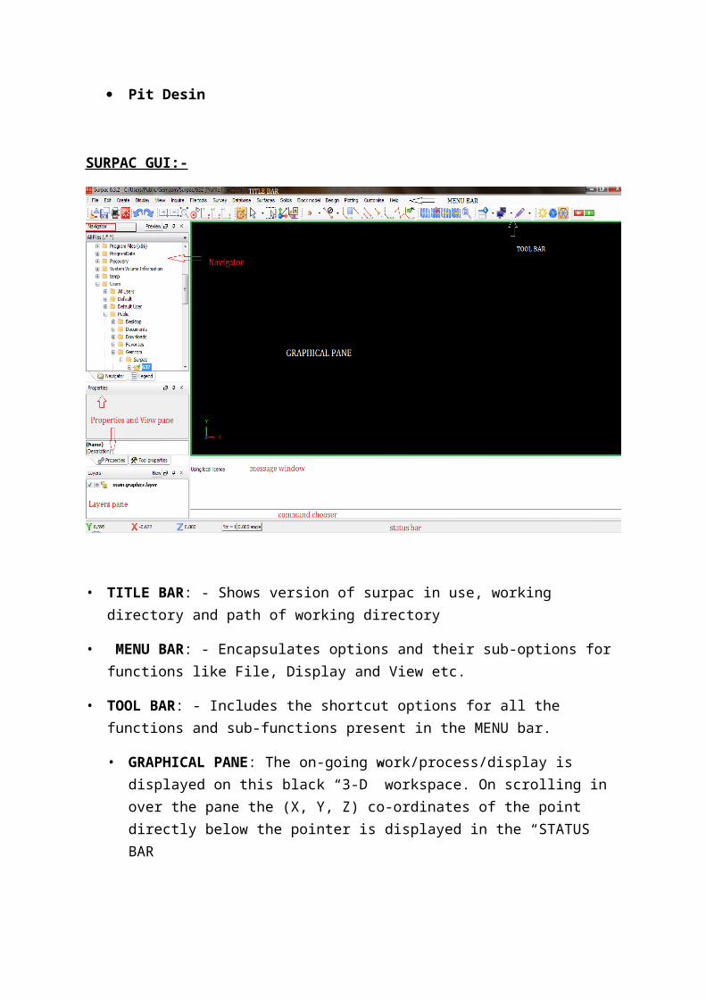
• TITLE BAR: - Shows version of surpac in use, working directory and path of working directory
• MENU BAR: - Encapsulates options and their sub-options for functions like File, Display and View etc.
• TOOL BAR: - Includes the shortcut options for all the functions and sub-functions present in the MENU bar.
• GRAPHICAL PANE: The on-going work/process/display is displayed on this black “3-D” workspace. On scrolling in over the pane the (X, Y, Z) co-ordinates of the point directly below the pointer is displayed in the “STATUS BAR
• NAVIGATOR: - All the folders and files can be browsed and selected via this window. "WORKING DIRECTORY” is set by choosing the same option via this navigator window.
• PROPERTIES AND VIEW PANE: - It displays the properties of file/folder selected via the navigator window. View pane shows the specifications of the particular property of the file/folder
• LAYERS PANE: - It shows all the layers being put to use along with the current active/working layer. Layers can be hide/deleted/activated and vice-versa using the functions given in the layers pane.
• MESSAGE WINDOW: - It shows all the steps being taken and errors/success of the function/process being done.
• COMMAND CHOOSER: - It allows user to input shortcut commands for fast working.
• STATUS BAR : - It Shows :-
1) Co-ordinates of the pointer
2) Current string file
3) Angle
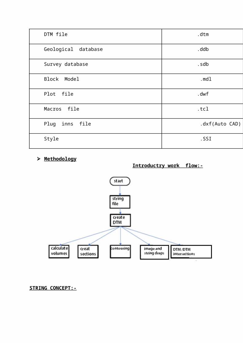
SURPAC DATATYPES :-
DATA TYPE EXTENSION
String file .str
DTM file .dtm
Geological database .ddb
Survey database .sdb
Block Model .mdl
Plot file .dwf
Macros file .tcl
Plug inns file .dxf(Auto CAD)
Style .SSI
Methodology Introductry work flow:-
STRING CONCEPT:-
The most common file format used for storing information in Surpac is a String file. A string file contains coordinate information for one or more points, as well as optional descriptive information for each point.
A string file can store up to 100 descriptions for a single point and can take 626 letters for each description
STRING HIERARCHY :-
Points > Segments > String
All points in a string file are grouped into segments, which are further grouped into strings.

A string file is a sequence of three dimensional coordinates delineating some physical feature
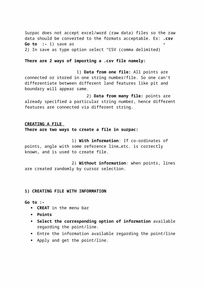
IMPORTING OF FILE TO SURPAC :-
Surpac does not accept excel/word (raw data) files so the raw data should be converted to the formats acceptable. Ex: .csv Go to :- 1) save as 2) In save as type option select “CSV (comma delimited)”
There are 2 ways of importing a .csv file namely:
1) Data from one file: All points are connected or stored in one string number/file. So one can’t differentiate between different land features like pit and boundary will appear same.
2) Data from many file: points are already specified a particular string number, hence different features are connected via different string.

CREATING A FILE There are two ways to create a file in surpac: 1) With information: If co-ordinates of points, angle with some reference line…etc. is correctly known, and is used to create file.
2) Without information: when points, lines are created randomly by cursor selection.
1) CREATING FILE WITH INFORMATION
Go to :- CREAT in the menu bar
Points
Select the corresponding option of information available regarding the point/line.
Entre the information available regarding the point/line
Apply and get the point/line.
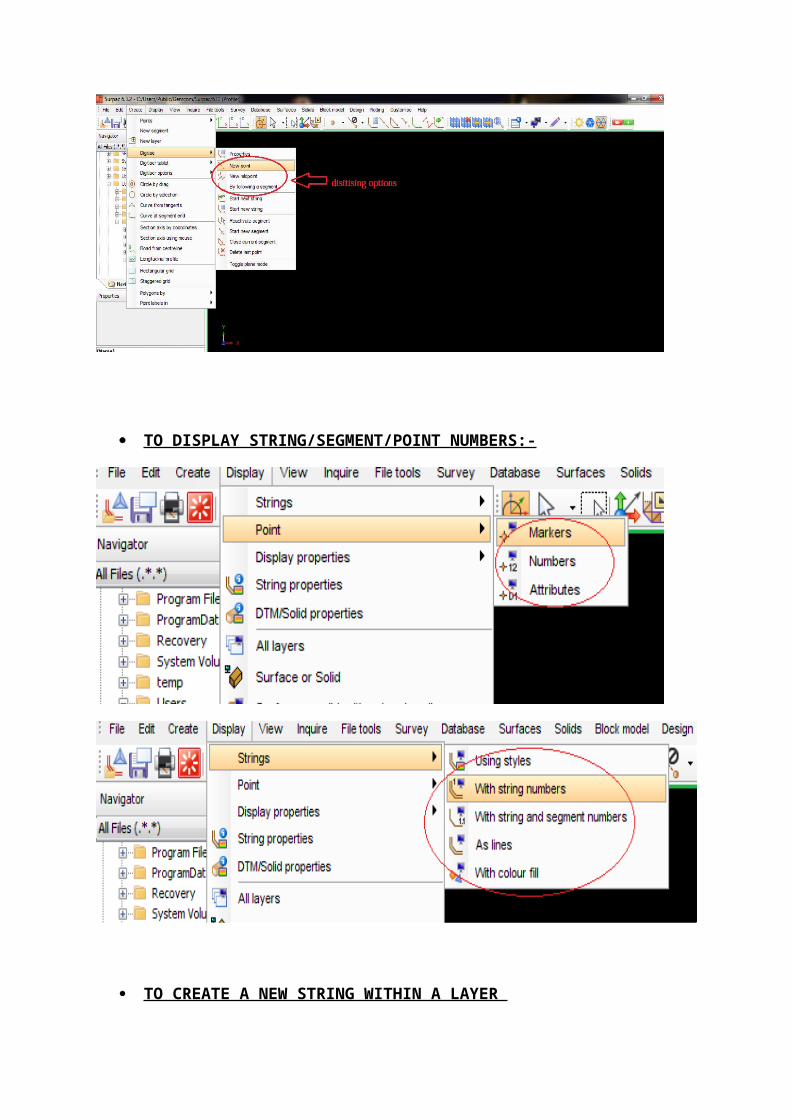
2) CREATING FILE WITHOUT INFORMATION Go to * CREAT >> Digitise >> New point Now click on the desired position to get a point, press “Esc” to deactivate the command.
There are more options in digitize and create >> point Tab that can be used to create file (point, line...Etc) demonstrated as follows:-
TO DISPLAY STRING/SEGMENT/POINT NUMBERS:-

TO CREATE A NEW STRING WITHIN A LAYER
Go to :- create >> Digitise >> properties >> window pops up.
Change the string number to get a new string, now work is stored in the specified string observable from the change in string color.
If any previous string/segment is needed to be REACTIVATED Go to create >> Digitise >> Reactivate segment/string >> click on the concerned segment/string.
Now work will be saved in this string/segment
To MERGE two files :-
Select both the files using Ctrl >> holding the Ctrl drag and drop both files in the graphical pane. Both files will be merged in a same/common layer.
Want to display a particular set of strings/segment :-
Go to Display >> Hide strings/segments >> in a layer >> Use the range concept.
TO INQUIRE POINT/SEGMENT/STRING PROPERTIES:- (Co-ordinates, bearing, angle, distance etc) Go to Inquire >> point/segment/string properties
TO CHANGE/MODIFY PROPERTIES OF POINTS/SEGMENTS/STRING
Go to Edit >> segment/point >> math’s >> click on segment to apply
Using point/segment/string math’s one can transform between points/segments/strings/co-ordinate.
TO SMOOTHEN A TRACE/STRING :-
Go to Edit >> string >> smooth >> window pops up
Now entre the desired strings/segments to be smoothened using Range concept, further entre the number of intermediate points to be used to smoothen the curve, by this entry Surpac will put intermediate points between two consecutive points and then join thus smoothening the curve/trace/string
CREATING A CIRCLE :- Create >> circle by drag >>click on the desired point and drag to digitise the circle >> entre the radius, arc distance(lesser the arc distance more smoother the circle will be).
IMPORTING DATA(ADVANCE/FULL PROCESS) :- Go to file >> select it and save it in .csv format to the working directory >> right click on the working directory folder and refresh to get the .csv file. Importing for making a string file File >> import >> data from one file/data from many file >> window pops.

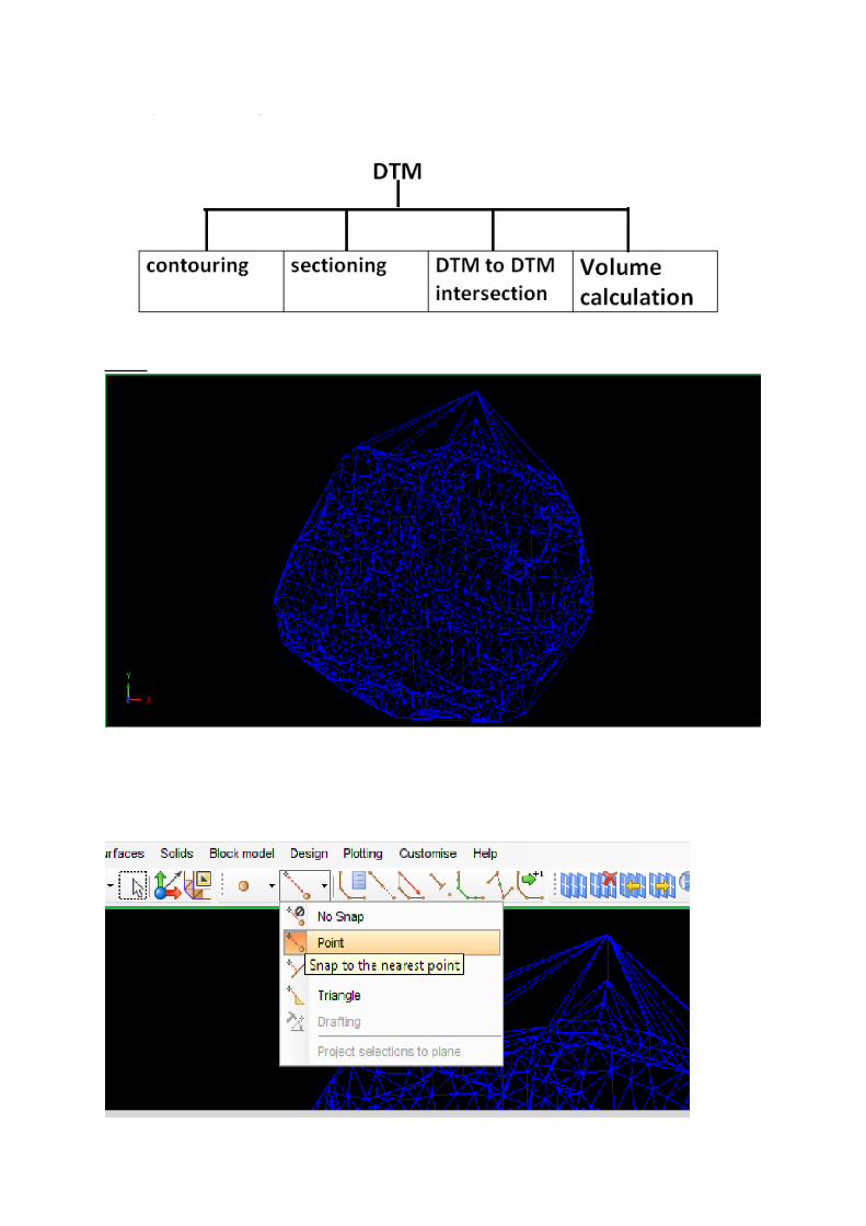
DIGITAL TERRAIN MODEL (DTM)
DTM CONCEPT:- A DTM surface is a set of triangles which represent a surface To create a DTM a relative string file is must Even to view a DTM in Surpac window its string file must exist Any editing in the string file after making DTM results loosing the DTM, the DTM is
to be created again
DTM DEPENDENCIES :-

DTM:-
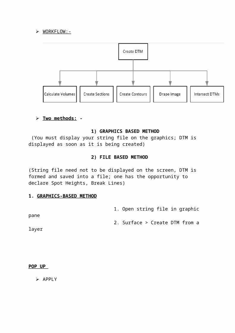
WORKFLOW:-

Two methods: -
1) GRAPHICS BASED METHOD (You must display your string file on the graphics; DTM is displayed as soon as it is being created)
2) FILE BASED METHOD
(String file need not to be displayed on the screen, DTM is formed and saved into a file; one has the opportunity to declare Spot Heights, Break Lines)
1. GRAPHICS-BASED METHOD
1. Open string file in graphic pane 2. Surface > Create DTM from a layer
POP UP
APPLY

(If there are crossovers then zoom in, move points or break the segment to remove it, then repeat the process from starting)
3. Save as
POP UP Apply
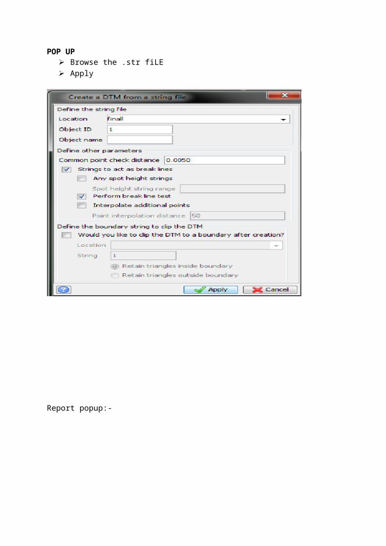
2. File-Based Method
1. Reset graphics 2. Surfaces > DTM File functions > Create DTM from string file
POP UP Browse the .str fiLE Apply
Report popup:-

Open saved .dtm file.
APPLICATIONS OF DTM:-

5. Digitize a boundary inside dtm edge
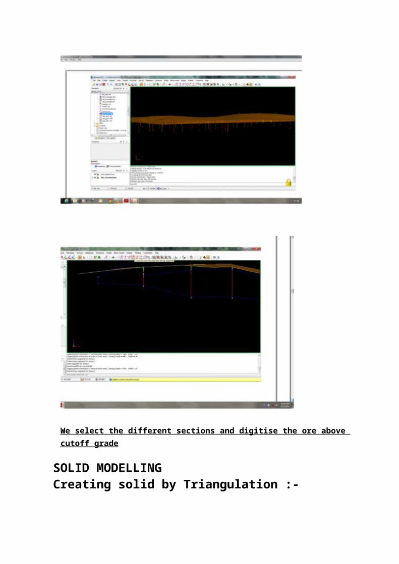
1st dtm > initial 2nd dtm > final Boundary string > saved layer Click detailed report Report by elevation > give range Apply
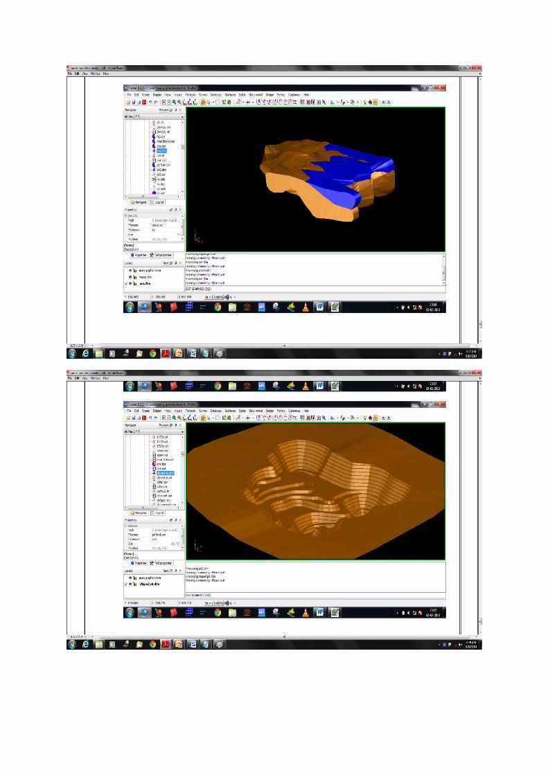
We select the different sections and digitise the ore above cutoff grade
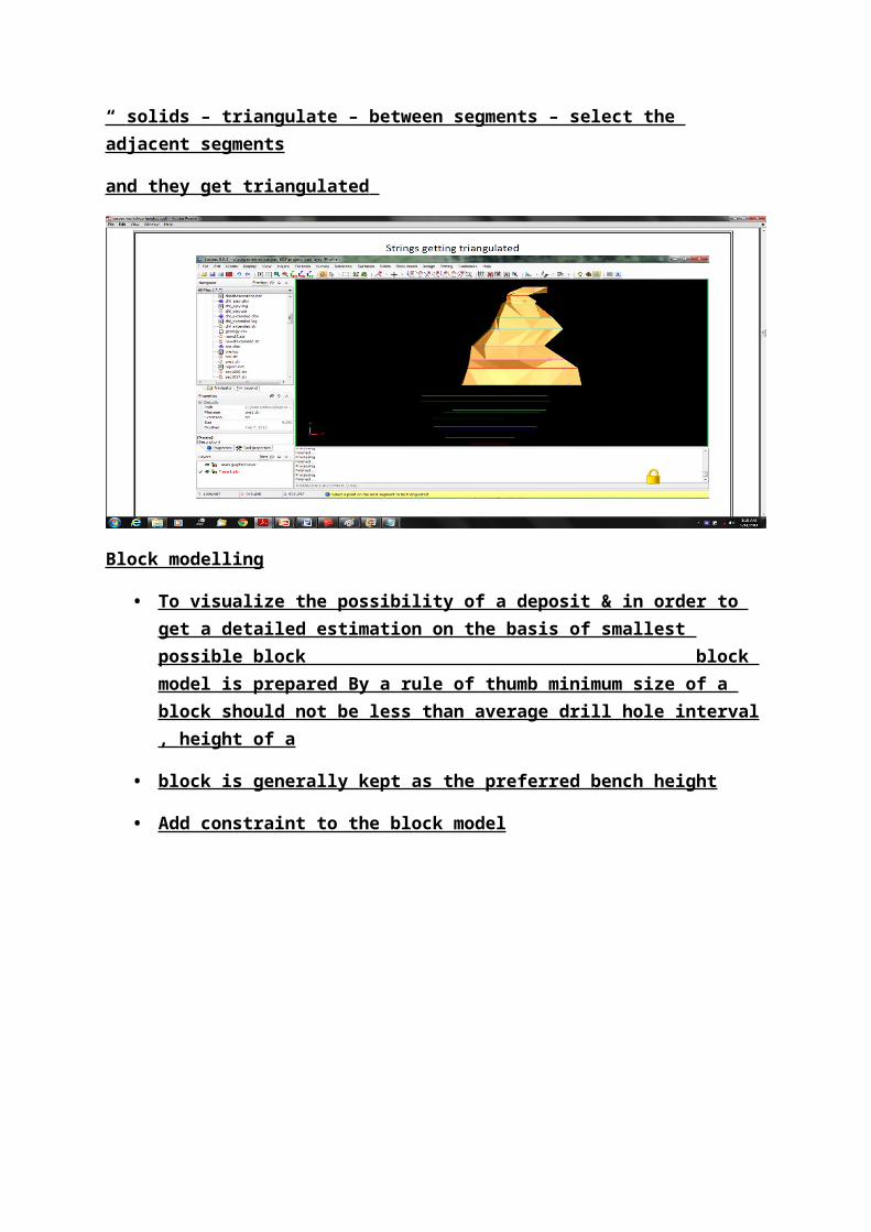
“ solids – triangulate – between segments – select the adjacent segments
and they get triangulated
SOLID MODELLINGCreating solid by Triangulation :-

Block modelling
• To visualize the possibility of a deposit & in order to get a detailed estimation on the basis of smallest possible block block model is prepared By a rule of thumb minimum size of a block should not be less than average drill hole interval , height of a
• block is generally kept as the preferred bench height
• Add constraint to the block model
•
• PIT DESIGNING
• Sections can be made along the constrained block at regular vertical spacings, here 10 m. These sections
• help in getting a better visualization of the variation of grade along the orebody
• & pit can be designed
• easily by extending the digitised ore in vertical direction .
• “ block model – sections – create”
• select normal to z axis in section type – give section range from block model summary report – apply
• give a location where slices to be formed get saved – check constrain model – define fe in model attribute –
• apply”
• select constraint in type – select constraint of ore – apply”
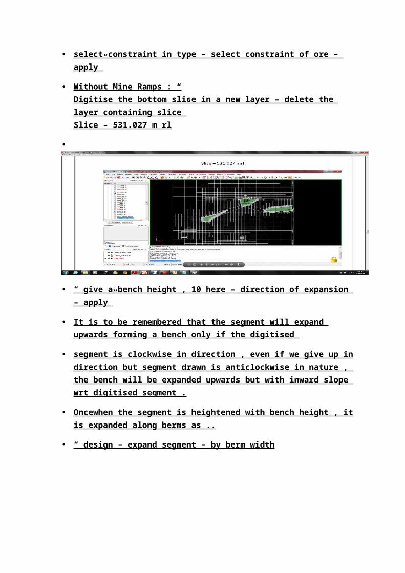
• Without Mine Ramps : “ Digitise the bottom slice in a new layer – delete the layer containing slice”Slice – 531.027 m rl
•
• “ give a bench height , 10 here – direction of expansion – apply”
• It is to be remembered that the segment will expand upwards forming a bench only if the digitised
• segment is clockwise in direction , even if we give up in direction but segment drawn is anticlockwise in nature , the bench will be expanded upwards but with inward slope wrt digitised segment .
• Oncewhen the segment is heightened with bench height , it is expanded along berms as ..
• “ design – expand segment – by berm width
To get the pit from string file formed by digitized segments , “ surfaces – dtm file function – from stringfile – select the saved file – apply ”The following dtm surface was formed .

• Lab/field work carried out
• We get data from Tata Noamundi iron ore opencast project
• Assay value
• Collar value
• Geology
• Survey data
• In lab we use surpac to make the Ultimate pit design
• -Analysis of investigation
• >After arranging the raw data and making pit design we analyse it to get:
• . Optimum place to start box cut to exploit the area
• .get extend and design of benches and ramp needed to extract the ore
• .extend of mining area to be leased
• Conclusion

• Thus we get the optimum pit design so that we can know the extend of lease hold area and extent of ming.
• We understand the proper location from where we have to start box cut.
• We get the solid model of deposit to know about the type and grade of ore.
WORK TO BE DONE :
Using variogram modeling for reserve estimation
Determine the primary and secondary variogram to know about the direction of maximum continuity
REFERENCES
Dowd, P. A , Onur A. H , Optimizing Open Pit Design and Sequencing, Proc. 23rd International APCOM Symposium,1992, pp- 411-422, 1992.
Hustrulid, W., Kutcha, M., Open pit mine planning and design, volume 1, Chapter 6 Production planning, pp- 601-605, A.A. Balkema publications, Rotterdam, Netherlands, 1995.
Lerchs H., Grossmann I. F., Optimum design of open pit mines, Canadian Institute of Mining Trans., 68, pp. 17-24,1965.
Ronson,K.A,Computerized open pit planning and the development and application of a software open pit planner, 2001.