
My Ph.D. Research
37
Major Research Computer Sciences Mechanical Engineering Mechanical Engineering Mechanical Analysis Computer Sciences Design Optimization Graphics User Interface Parallel Computation
-
Upload
po-ting-wu -
Category
Technology
-
view
316 -
download
0
Transcript of My Ph.D. Research
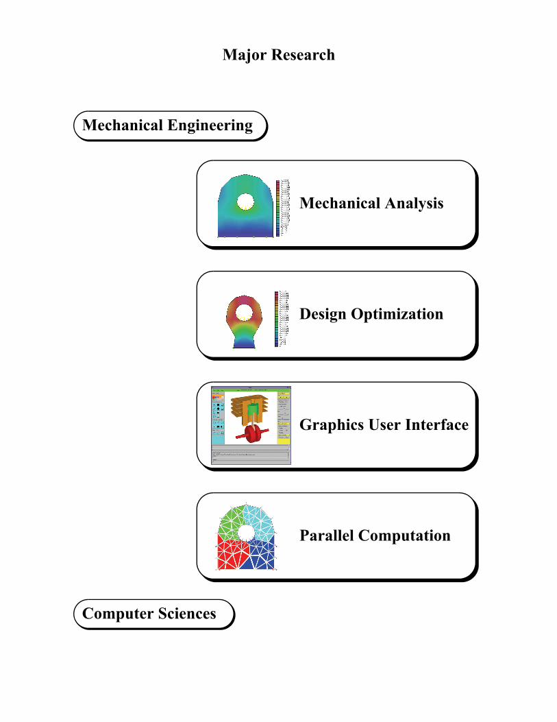
Major Research
Computer Sciences
Mechanical EngineeringMechanical Engineering
Mechanical Analysis
Computer Sciences
Design Optimization
Graphics User Interface
Parallel Computation

PPrroobblleemm SSoollvviinngg EEnnvviirroonnmmeenntt
CCoommppuutteerr AApppplliiccaattiioonn
PPaarraalllleell // DDiissttrriibbuutteedd GGrraapphhiiccss UUsseerr IInntteerrffaaccee
NNeettwwoorrkk CCoommppuuttiinngg
SSyysstteemm--LLeevveell
OObbjjeecctt--OOrriieenntteedd ((OOOOMMPPII))
PPoorrttaabbllee PPrroottooccooll ((MMPPII))
IIPPCC TTCCPP // IIPP
EEnnggiinneeeerriinngg SSiimmuullaattiioonn
SShhaappee OOppttiimmiizzaattiioonn
AAuuttoommaattiicc DDiiffffeerreennttiiaattiioonn
CCoommppiilleerr TTeecchhnnoollooggyy
FFiinniittee EElleemmeenntt AAnnaallyyssiiss

lel Programming
Portable
MPI Library
un, SGI, PC Linux, DEC, IBM RS-000
Workstation Cluster
messages passingsockets, telnet, rlogin
UNIX
CPU
MemCPU
Mem
CPU
Mem
CPU
Mem
UNIX UNIX
UNIX
ortable
MPI (Message - Passing Interface) -- Portable Paral
MPI Library
Sun Solaris multi-processors, SGI Challenge, Windows NT, OS/2 SMP
Parallel Extension
UNIX, WindowsNT, OS/2
CPU CPU CPU CPU
Memory
Shared Memory Machines
shared access to main memoryread / write
Parallel Extensions NOT Compatible -- Software NOT
MPI Library
nCUBE, Intel IPSC, Intel Paragon,CM-5
Parallel Extension
UNIX
CPU
Mem
Distributed Memory Machines
messages passingsend / recv
S6
CPU
Mem
CPU
Mem
CPU
Mem
MPI Applications -- Parallel / Distributed Software P

Multithreaded Programming Graphics User Interface: X-Window Event + Communication Message (IPC, TCP/IP) Client / Server for Parallel Computation:
1. Client: Computing + Receiving Results
2. Server: Sending Results + Computing Job Scheduling – Task Management: Synchronization + Load Balancing
Parallel Computing without Task Manager
Parallel Computing with Task Manager JAVA Threads:
1. Synchronization (Image Loading)
2. Concurrency (Slide Show, Clock)

Shallow Water Equations Model (SWE)

Performance of Parallel Computation - ParaGraph

Performance of Parallel Computation - Upshot

n of Physical Parts
odeling
nternal iteration
Convergencestimate
alysis &ptimization
ral Analysis
ve Approachmesh density
no
yes
Postprocessing
Parallel ShapeOptimization
Design OptimumEstimate
yes
no
vity Analysis
An Abstract View of the EPPOD System for the Desig
Prototype
InitialDesign
Model Description
PATRAN CommandLanguage
ModelSelection
ImprovedDesign
Interactive Input
M
i
Error E
AnLocal O
Structu
Adapti- new
Global Optimization
yes
no
Parallel DesignSensitivity Analysis
Parallel ShapeOptimization
Design OptimumEstimate
Sensiti
external iteration
XXoX CSGLanguage
Preprocessing
ParallelOptimal Domain Decomposition
Parallel MeshGeneration
Mesh Refiner

ment
mesh & splitting
simulation
The Tools of a Problem Solving Environ
Geometry Specification
geometry specificationMesh Generation
Mesh Splitting
Structural Analysis
Shape Optimization
optimization

The Flow Diagram of the Implemented EPPOD System
FEA result
FEA result
cancel
FEA start
boundarymesh
ADS Computation
If Restart
Yes
No
No
No
No
No
Yes
Yes Yes
Pause
YesStop
FEM Pre-Processor
Mesh Generation
Domain Decomposition
(X-Windows Server)
FEM Processor
Displacement Analysis
Stress Analysis
Object Analysis
(X-Windows Server)
FEM Post-Processor
FEM mesh Display
FEM contour Display
Deformation Display
(X-Windows Server)
ADS Initialization
Stop
Stop
Start
If Interrupt
If Converge
If Error
If Pause

EPPOD - Electronic Prototyping for Physical Object Design Interactive System
FEM Pre-Processor Server
FEM Post-Processor Server
FEM Processor Server

UNION
ION ROTATE
Box - 1
er - 2
TRANSLATE
Cylinder - 3
Geometry Definition
XXoX: CSG (Constructive Solid Geometry) Language
cylinder1 = cylinder(0,0,-0.52,1.56,1.04)cylinder2 = cylinder(0,0,-0.52,1.04,1.04)cylinder3 = cylinder(0,0,0,0.5,5.4)box1 = box(-0.26,-0.52,1.04,0.52,1.04,6.6)rod = rotate(cylinder1-cylinder2,0,0,0,0,1,0,-90)rod = rod | box1 | translate(scale(rod,1,0.5,0.5),0,0,8.16)rod = rod | translate(rotate(cylinder3,0,0,0,0,1,0,-90),2.6,0,8.16)
CSG Tree:
DIFFER
ROTATE
TRANSLATEUN
UNION
Cylind
SCALE
Cylinder - 1

deling System
Viewing
Information
XXoX - An Interactive X-Window based Solid Mo
Menu
Operation
Message
Command
Drawing

ftwares
VRML
Rendering #3
Interfaces between XXoX and Foreign So
PATRAN
Rendering #1
Rendering #2

ftwares
XPoly
Rendering #3
Interfaces between XXoX and Foreign So
PATRAN
Rendering #1
Rendering #2

Virtual Reality Modeling Language (VRML) Interface

ethodology
esh of step ed to a finer arallel.
5. An optimal mesh splitting scheme to mini-mize the bisection width is applied.
Parallel Mesh Generation and Decomposition M
1. An adaptive mesh algorithm is invoked to gener-ate an initial “coarse” mesh.
2. A scheme to split the initial mesh into equal-sized subdomains is applied.
3. A linking rou-tine to form the new subdomain boundaries is called.
4. The malgorithm1 is appligenerate mesh in p

Windows of the GUI for Mesh Generation and Splitting
Triangular element mesh generation & element-wise domain decomposition
Triangular element mesh generation & node-wise domain decomposition
Quadrilateral element mesh generation & element-wise domain decomposition

Adaptive Ap
Deformed shape
Stress: <-7789.59, 6769.68>
Error: 0.164/2.10E-5
79 nodes, 117 elements
15 refine pointsin
one adaptive step
Deformed shape
Stress: <-16446.6, 8286.24>
Error: 1.427/8.68E-5
136 nodes, 222 elements
proach

Performance of Parallel Mesh Generation - Engine Rod
Utilization Count: states of idle, overhead, and busy as function of time.
Utilization Summary: overall cumulative percent-age of time in idle, overhead, and busy states.
Speedup - sequential : T1s / Tp.Speedup - parallel : T1 / Tp.
Engine Rod
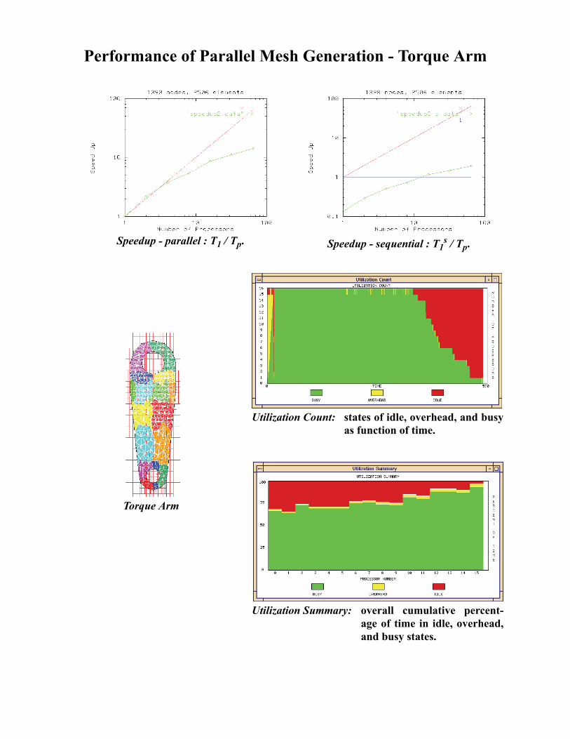
Performance of Parallel Mesh Generation - Torque Arm
Utilization Count: states of idle, overhead, and busy as function of time.
Utilization Summary: overall cumulative percent-age of time in idle, overhead, and busy states.
Speedup - sequential : T1s / Tp.Speedup - parallel : T1 / Tp.
Torque Arm

Performance of Parallel Mesh Generation - Engine Axis
Utilization Count: states of idle, overhead, and busy as function of time.
Utilization Summary: overall cumulative percent-age of time in idle, overhead, and busy states.
Speedup - sequential : T1s / Tp.Speedup - parallel : T1 / Tp.
Engine Axis

Performance of Parallel Mesh Generation (Paragon) - Ex1d
SpeedUp : T1 / Tp & T1s / Tp

Performance of Parallel Mesh Generation (Paragon) - Ex1d
SpeedUp : T1 / Tp & T1s / Tp

Performance of Parallel Mesh Generation (nCUBE) - Ex3a
SpeedUp : T1 / Tp & T1s / Tp

Performance of Parallel Mesh Generation (nCUBE) - Ex3a
SpeedUp : T1 / Tp & T1s / Tp

Mesh Decomposition and Sparse Matrix - Engine Rod
DFS - basicCommunication: 17 / 10 Bandwidth: 4 / 24Connectivity: 51 IBV: 28
BFS - domain-wiseCommunication: 8 / 4 Bandwidth: 7 / 15Connectivity: 16 IBV: 15
BFS - strip-wiseCommunication: 15 / 8 Bandwidth: 9 / 16Connectivity: 30 IBV: 22
Eigenvector SpectralCommunication: 7 / 5 Bandwidth: 7 / 22Connectivity: 14 IBV: 12
Polar - recursive bisectionCommunication: 16 / 11 Bandwidth: 2 / 6Connectivity: 48 IBV: 29
Inertia - first eigenvectorCommunication: 12 / 6 Bandwidth: 7 / 17Connectivity: 36 IBV: 19
Polar - local optimumCommunication: 8 / 5 Bandwidth: 5 / 11Connectivity: 16 IBV: 15
Cartesian - local optimumCommunication: 7 / 4 Bandwidth: 6 / 15Connectivity: 14 IBV: 14

Mesh Decomposition and Sparse Matrix - Engine Cap
DFS - basicCommunication: 46 / 14 Bandwidth: 5 / 41Connectivity: 322 IBV: 222
BFS - domain-wiseCommunication: 25 / 9 Bandwidth: 9 / 24Connectivity: 150 IBV: 151
BFS - strip-wiseCommunication: 77 / 42 Bandwidth: 19 / 45Connectivity: 154 IBV: 363
Eigenvector SpectralCommunication: 19 / 8 Bandwidth: 11 / 44Connectivity: 95 IBV: 125
Polar - recursive bisectionCommunication: 39 / 16 Bandwidth: 3 / 9Connectivity: 273 IBV: 188
Inertia - first eigenvectorCommunication: 57 / 30 Bandwidth: 13 / 42Connectivity: 255 IBV: 287
Polar - local optimumCommunication: 20 / 8 Bandwidth: 8 / 22Connectivity: 80 IBV: 124
Cartesian - local optimumCommunication: 25 / 9 Bandwidth: 7 / 17Connectivity: 120 IBV: 152

Mesh Decomposition and Sparse Matrix - Engine Axis
DFS - basicCommunication: 286 / 143 Bandwidth: 39 / 818Connectivity: 858 IBV: 412
BFS - domain-wiseCommunication: 18 / 10 Bandwidth: 34 / 73Connectivity: 36 IBV: 36
BFS - strip-wiseCommunication: 62 / 43 Bandwidth: 55 / 101Connectivity: 124 IBV: 80
Eigenvector SpectralCommunication: 20 / 10 Bandwidth: 111 / 861Connectivity: 40 IBV: 36
Polar - recursive bisectionCommunication: 131 / 104 Bandwidth: 13 / 57Connectivity: 387 IBV: 251
Inertia - first eigenvectorCommunication: 65 / 49 Bandwidth: 54 / 219Connectivity: 130 IBV: 114
Polar - local optimumCommunication: 51 / 27 Bandwidth: 22 / 135Connectivity: 102 IBV: 100
Cartesian - local optimumCommunication: 67 / 48 Bandwidth: 47 / 163Connectivity: 134 IBV: 85

Performance of Mesh Decomposition
Maximum Interface Length
BandwidthInterpartitioning Boundary Vertices
Subdomain Connectivity
Computation Time
Methods
CLO Cartesian Local OptimumPLO Polar Local OptimumCLE Cartesian Longest ExpansionMRSB Multilevel Recursive Spectral BisectionGreedy Domain-Wise BFSRCM Strip-Wise BFSInert Inertia - First Eigenvector

e Optimization
Iter# 5,6 (eval# 81,97)
Iter# 7-10 (eval# 100-122)
Iter# 4 (eval# 65)
Numerical Performance for the Traditional Shap
Iter# 1 (eval# 17)
Iter# 0 (Initial Design)
Iter# 3 (eval# 49)Iter# 2 (eval# 33)
Traditional Shape Optimization

tion Method
Local Iter# 3 (eval# 15/51)
Global Iter# 3
Global Iter# 2
Numerical Performance for the Model Coordina
Local Iter# 1 (eval = 5/17)
Iter# 0 (Initial Design)
Local Iter# 2 (eval# 10/34)Global Iter# 1
Model Coordination Shape Optimization

Parallel Electronic Prototyping - Engine Rod
81 nodes, 117 elements
Shape OptimizationZ = Area min.dispalcement 0.00050.1 Xi-j 1.0 i = 1, 2
j = 1, 20.5 X3-j 1.0 j = 1, 20.5 X4-j 1.0 j = 1, , 7
Deformed shape
X1-1
X4-2
X1-2
X2-2
X3-2
X4-6
X4-5X4-3
X3-1
X2-1
X4-4
X4-1 X4-7
49 nodes, 63 elements
Displacement
Stress
Deformed shape
Displacement
Stress

Parallel Electronic Prototyping - Torque Arm
110 nodes, 152 elements
Shape OptimizationZ = Area min.dispalcement 0.0015stress 100000.1 Xi-j 1.0 i = 1, 2
j = 1, 20.5 Xi-j 1.0 i = 3, 4
j = 1, 20.5 X5-j 1.0 j = 1, , 50.2 Xi-j 1.2 i = 6, 7
j = 1, 20.35 X8-j 0.6 j = 1, 20.35 X9-j 1.0 j = 1, , 50.2 R1 = X10 0.450.15 R2 = X11 0.275
Deformed shape
X1-1
120 nodes, 148 elements
Displacement
Stress
Deformed shape
Displacement
Stress
X2-1X3-1
X4-1
X5-3X5-2X5-1
X1-1
X5-4
X5-5
X4-2X3-2X2-2X1-2
X6-2
X7-1
X6-1
X7-2
X8-2X9-1 X9-5
X9-3X9-4X9-2
X8-1
R1=X10
R2=X11

Performance of Parallel Shape Optimization - Engine Rod
Speedup - parallel : T1 / Tp.
Engine Rod
Utilization Countstates of idle, overhead, and busy as function of time.
Utilization Summaryoverall cumulative percentage of time in idle, overhead, and busy states.
proc#=4
proc#=16

Performance of Parallel Shape Optimization - Torque Arm
Speedup - parallel : T1 / Tp.
Torque Arm
Utilization Countstates of idle, overhead, and busy as function of time.
Utilization Summaryoverall cumulative percentage of time in idle, overhead, and busy states.
proc#=4
proc#=16

Finite Element Analysis Post-Processor - Xcontour
Result of Structural Stress
Contour Lines
Numbering of FEM Mesh
Deformed Shape