
My Paper Research
18
جJournal of Engineering Volume 18 June 2012 Number 6 717 Experimental and numerical evaluation of friction stirs welding of AA 2024-W aluminum alloy Dr.Ayad M. Takhakh Hamzah N. Shakir [email protected] [email protected] Abstract Friction Stir Welding (FSW) is one of the most effective solid states joining process and has numerous potential applications in many industries. A FSW numerical tool, based on ANSYS F.E software, has been developed. The amount of the heat gone to the tool dictates the life of the tool and the capability of the tool to produce a good processed zone. Hence, understanding the heat transfer aspect of the friction stir welding is extremely important for improving the process. Many research works were carried out to simulate the friction stir welding using various softwares to determine the temperature distribution for a given set of welding conditions. The objective of this research is to develop a finite element simulation of friction stir welding of AA2024-W Aluminium alloy. Numerical simulations are developed for thermal conductivity, specific heat and density to know the relationship of these factors with peak temperature. Variation of temperature with input parameters is observed. The simulation model is tested with experimental results. The results of the simulation are in good agreement with that of experimental results. ﺑﺎﻟﻤﺰج اﻻﺣﺘﻜﺎآﻲ ﻟﻠﺤﺎم واﻟﺮﻗﻤﻴﺔ اﻟﻌﻤﻠﻴﺔ اﻟﺤﻠﻮل) FSW ( اﻟﻤﻨﻴﻮم ﻟﺴﺒﻴﻜﺔAA2024-W أ. م. د. م ﻃﺨﺎخ ﻣﺮاد أﻳﺎد. ﺷﺎآﺮ ﻧﻮراﻟﺪﻳﻦ ﺣﻤﺰة اﻟﻨﻬﺮﻳﻦ ﺟﺎﻣﻌﺔ/ اﻟﻬﻨﺪﺳﺔ آﻠﻴﺔ اﻟﺨﻼﺻﺔ ﺑﺎﻟﻤﺰج اﻻﺣﺘﻜﺎآﻲ اﻟﻠﺤﺎم ﻳﻌﺪ) FSW ( ﻣﻦ واﺣﺪ اﻟ اﻟﻔﻌﺎﻟﺔ ﻄﺮق اﻟﺼﻨﺎﻋﺎت ﻣﺨﺘﻠﻒ ﻓﻲ اﻟﺘﻄﺒﻴﻘﺎت ﻣﻦ اﻟﻜﺜﻴﺮ ﻓﻲ وﻳﺪﺧﻞ اﻟﺼﻠﺒﺔ اﻟﺤﺎﻟﺔ ﻟﻠﺤﺎم. ﺗﻄﻮﻳﺮ ﺗﻢ ﺣﻠﻮل ﺑﺎﻻﻋﺘﻤﺎد ﺑﺎﻟﻤﺰج اﻻﺣﺘﻜﺎآﻲ ﻟﻠﺤﺎم رﻗﻤﻴﺔ ﺑﺮﻧﺎﻣﺞ ﻋﻠﺮANSYS واﻟﺘﻲ اﻟﻠﺤﺎم ﻋﻤﻠﻴﺔ ﺧﻼل اﻟﻤﺘﻮﻟﺪة اﻟﺤﺮارة آﻤﻴﺔ ﻟﺤﺴﺎب آ ﻣﻌﺮﻓﺔ اﻟﻤﻬﻢ ﻣﻦ ان اذ واﻟﻌﺪة، اﻟﻠﺤﺎم ﻣﻨﻄﻘﺔ وﺟﻮدة ﻋﻤﺮ ﻋﻠﻰ ﺗﺆﺛﺮ ﺑﺎﻟﻤﺰج اﻻﺣﺘﻜﺎآﻲ اﻟﻠﺤﺎم ﺧﻼل اﻟﺤﺮارة اﻧﺘﻘﺎل ﻴﻔﻴﺔ. اﻟﺒﺎﺣﺜﻴﻦ ﻣﻦ ﻋﺪد ﻣﺘﻌﺪدة ﺑﺮاﻣﺠﻴﺎت ﺑﺎﺳﺘﺨﺪام اﻟﻠﺤﺎم ﻣﻦ اﻟﻨﻮع هﺬا ﺧﻼل اﻟﺤﺮارة درﺟﺎت ﺗﻮزﻳﻊ درﺳﻮ. ﺑﺎﺳﺘﺨﺪام رﻗﻤﻴﺔ ﺣﻠﻮل ﺗﻄﻮﻳﺮ اﻟﺒﺤﺚ هﺬا ﻣﻦ اﻟﻐﺮض اﻟﻤﺤﺪدة اﻟﻌﻨﺎﺻﺮ ﻃﺮﻳﻘﺔ) FEM ( ﺑﺮﻧﺎﻣﺞ ﻋﻠﻰ ﺑﺎﻻﺳﺘﻨﺎدANSYS اﻟﻤﻨﻴﻮم ﻟﺴﺒﻴﻜﺔ ﻧﻮعAA2024-W . ﺑﺎﻻﻋﺘﻤﺎد اﻟﺤﻠﻮل هﺬﻩ ﺗﻄﻮﻳﺮ ﺗﻢ درﺟﺎت ﺑﺘﻐﻴﺮ اﻟﺨﻮاص هﺬﻩ ﺗﺘﻐﻴﺮ ﺣﻴﺚ اﻟﺤﺮارة درﺟﺎت ﻣﻊ اﻟﻜﺜﺎﻓﺔ و اﻟﻨﻮﻋﻴﺔ اﻟﺤﺮارة و اﻟﺤﺮاري اﻟﺘﻮﺻﻴﻞ ﺧﻮاص ﺗﺮﺑﻂ اﻟﺘﻲ اﻟﻌﻼﻗﺔ ﻋﻠﻰ اﻟﺤﺮارة. و اﻟﻤﻘﺎرﻧﺔ ﻧﺘﺎﺋﺞ واﻇﻬﺮت ﻧﺘﺎﺋﺠﻬﺎ ﻣﻦ ﻋﻤﻠﻴﺎ اﻟﺘﺤﻘﻖ ﺗﻢ ﻋﻠﻴﻬﺎ اﻟﺤﺼﻮل ﺗﻢ اﻟﺘﻲ اﻟﻤﺤﺎآﺔ ﺟﻴﺪ ﺗﻮاﻓﻖ ﺟﻮد. Keywords: Friction stir welding, AA 2024-W, Temperature distribution, Simulation.
description
My Paper Research
Transcript of My Paper Research

ج
Journal of Engineering Volume 18 June 2012 Number 6
717
Experimental and numerical evaluation of friction stirs welding of AA 2024-W aluminum alloy
Dr.Ayad M. Takhakh Hamzah N. Shakir
[email protected] [email protected] Abstract
Friction Stir Welding (FSW) is one of the most effective solid states joining process and has
numerous potential applications in many industries. A FSW numerical tool, based on ANSYS F.E software,
has been developed. The amount of the heat gone to the tool dictates the life of the tool and the capability of
the tool to produce a good processed zone. Hence, understanding the heat transfer aspect of the friction stir
welding is extremely important for improving the process. Many research works were carried out to simulate
the friction stir welding using various softwares to determine the temperature distribution for a given set of
welding conditions. The objective of this research is to develop a finite element simulation of friction stir
welding of AA2024-W Aluminium alloy. Numerical simulations are developed for thermal conductivity,
specific heat and density to know the relationship of these factors with peak temperature. Variation of
temperature with input parameters is observed. The simulation model is tested with experimental results. The
results of the simulation are in good agreement with that of experimental results.
لسبيكة المنيوم )FSW(الحلول العملية والرقمية للحام االحتكاآي بالمزج
AA2024-W
حمزة نورالدين شاآر. أياد مراد طخاخ م. د.م.أ
آلية الهندسة/ جامعة النهرين
الخالصة
. للحام الحالة الصلبة ويدخل في الكثير من التطبيقات في مختلف الصناعات طرق الفعالةال واحد من )FSW(يعد اللحام االحتكاآي بالمزج لحساب آمية الحرارة المتولدة خالل عملية اللحام والتي ANSYS علر برنامج رقمية للحام االحتكاآي بالمزج باالعتماد حلولتم تطوير
عدد من الباحثين . يفية انتقال الحرارة خالل اللحام االحتكاآي بالمزجتؤثر على عمر وجودة منطقة اللحام والعدة، اذ ان من المهم معرفة آالغرض من هذا البحث تطوير حلول رقمية باستخدام . درسو توزيع درجات الحرارة خالل هذا النوع من اللحام باستخدام برامجيات متعددة
تم تطوير هذه الحلول باالعتماد . AA2024-W نوع لسبيكة المنيومANSYS باالستناد على برنامج )FEM(طريقة العناصر المحددة على العالقة التي تربط خواص التوصيل الحراري و الحرارة النوعية و الكثافة مع درجات الحرارة حيث تتغير هذه الخواص بتغير درجات
. جود توافق جيد المحاآة التي تم الحصول عليها تم التحقق عمليًا من نتائجها واظهرت نتائج المقارنة و. الحرارة
Keywords: Friction stir welding, AA 2024-W, Temperature distribution, Simulation.
Experimental and numerical evaluation of friction stirs welding of AA 2024-W aluminum alloy
Dr.Ayad M. Takhakh Hamzah N. Shakir
718
Introduction
A method of solid phase welding, which
permits a wide range of parts and geometries
to be welded and called friction stir welding
(FSW), was invented by W. Thomas and his
colleagues of The Welding Institute (TWI),
UK, in 1991. Friction stir welding can be used
for joining many types of material and metal
combinations, if tool material and designs can
be found which operate at the forging
temperature of the workpieces. The process
has been used for manufacture of butt welds,
overlap welds, T-sections and corner welds.
For each of these joint geometries specific
tool designs are required which are being
further developed and optimized [1,2].
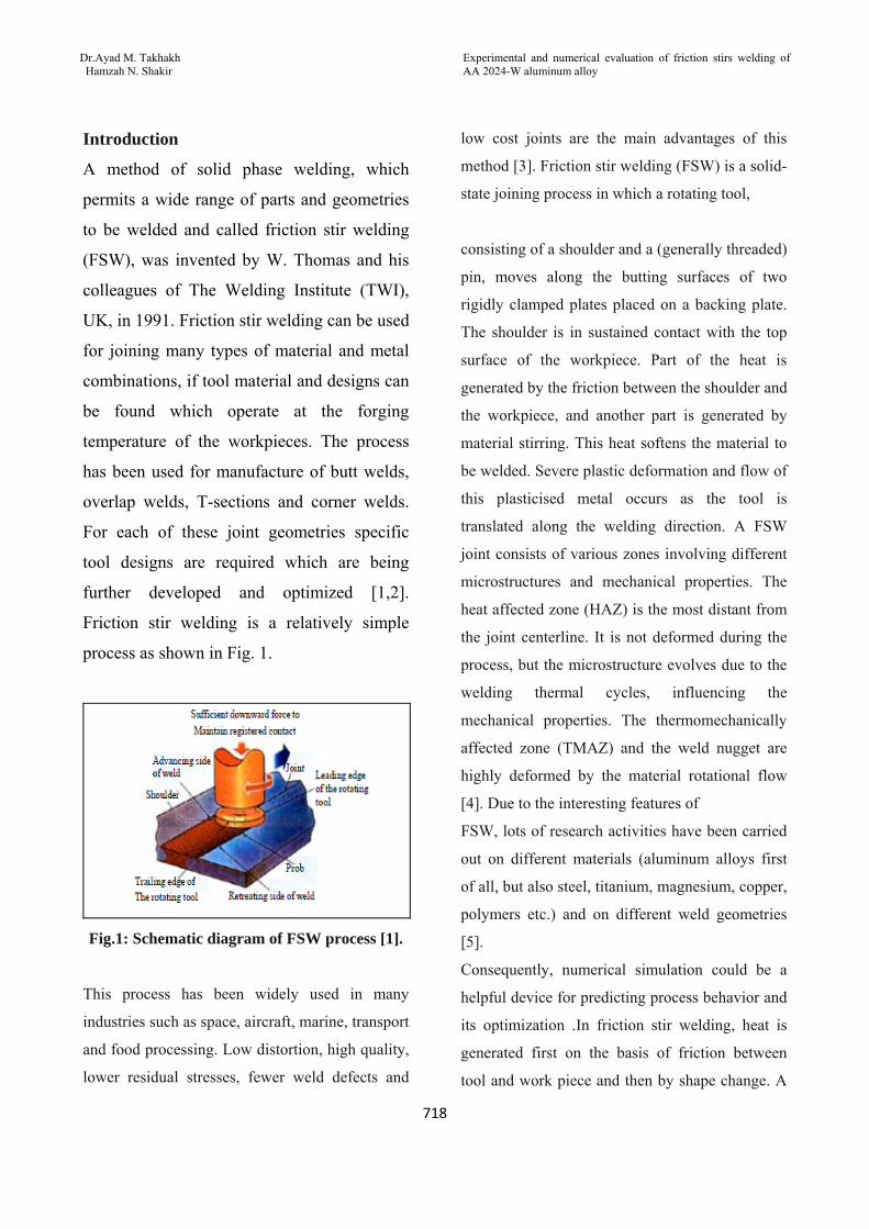
Friction stir welding is a relatively simple
process as shown in Fig. 1.
Fig.1: Schematic diagram of FSW process [1].
This process has been widely used in many
industries such as space, aircraft, marine, transport
and food processing. Low distortion, high quality,
lower residual stresses, fewer weld defects and
low cost joints are the main advantages of this
method [3]. Friction stir welding (FSW) is a solid-
state joining process in which a rotating tool,
consisting of a shoulder and a (generally threaded)
pin, moves along the butting surfaces of two
rigidly clamped plates placed on a backing plate.
The shoulder is in sustained contact with the top
surface of the workpiece. Part of the heat is
generated by the friction between the shoulder and
the workpiece, and another part is generated by
material stirring. This heat softens the material to
be welded. Severe plastic deformation and flow of
this plasticised metal occurs as the tool is
translated along the welding direction. A FSW
joint consists of various zones involving different
microstructures and mechanical properties. The
heat affected zone (HAZ) is the most distant from
the joint centerline. It is not deformed during the
process, but the microstructure evolves due to the
welding thermal cycles, influencing the
mechanical properties. The thermomechanically
affected zone (TMAZ) and the weld nugget are
highly deformed by the material rotational flow
[4]. Due to the interesting features of
FSW, lots of research activities have been carried
out on different materials (aluminum alloys first
of all, but also steel, titanium, magnesium, copper,
polymers etc.) and on different weld geometries
[5].
Consequently, numerical simulation could be a
helpful device for predicting process behavior and
its optimization .In friction stir welding, heat is
generated first on the basis of friction between
tool and work piece and then by shape change. A

ج
Journal of Engineering Volume 18 June 2012 Number 6
719
portion of the generated heat disseminated
through work piece, will affect distortion, residual
stress distribution as well as weld quality of the
piece [6]. Finite element analysis is an effective
method in the investigation of welding, because it
not only can obtain the instantaneous results
during welding process, but also can save research
time and cost [7]. Some studies of FSW on
temperature field and residual stresses have been
carried out through FEM software i. e. ANSYS®
[8-9], ABAQUS [10-13], Forge® [14],
DEFORM-3DTM[15]. Finite element Methods also
used to study the effect of FSW process
parameters on mechanical properties of various
welded alloys based on solid mechanics [16] or
develop the mathematical model. [17].
Thus, much research has been done to study the
simulation of temperature distribution during
friction stir welding process. This was recognized
in present study based on ANSYS software, the
results obtained for simulation was comparison
with that actual experiment.
Experimental work Friction stir welds were made on the plate samples of 2024-Waluminum alloy on –W treatment which used to describe an as quench condition between solution heat treatment and artificial or room temperature aging. The test plates of size 200 mm X 100 mm X 3.5
mm are prepared from aluminum alloy AA2024
plates Fig.2. The chemical composition and
mechanical properties of the base material are
presented in Table 1 and Table 2, respectively.
The experiment is conducted using FSW machine
developed by TAKSAN milling machine, as
shown in Fig.3.The welding was done by single
pass.
Table 1: Chemical composition of Al 2024-W alloy.
Al Cr Mg Si Ti Mn Ni Fe Cu Zn Element
93.83 0.006 1.39 0.16 0.005 0.38 0.02 0.3 3.87 0.06 Weight
%measured
- - 1.5 0.18 - - - - 4.4 - Standard [24]
Table 2: Typical mechanical properties of wrought aluminum 2024-W alloy.
Hardness HV
Percentage of elongation
Yield strength(MPa)
Ultimate strength(MPa)
105 22% - 365 Measured
110 28% 335 Standard [25]

Experimental and numerical evaluation of friction stirs welding of AA 2024-W aluminum alloy
Dr.Ayad M. Takhakh Hamzah N. Shakir
720
Fig 2 :Dimensions of welded
plate
Fig. 3: Taksan milling machine
The FSW tools are manufactured using
Turning machine. The configuration of the
designed FSW Tool is:
• Tool pin profile of cylindrical without draft.
• Tools having ratio of shoulder diameter to
pin diameter(D/d) is 3 has been chosen for
this study because it is having good joining
properties among various pin configurations
[17].The manufactured tool is shown in Fig.
4.
The research work was planned to be carried
out in the following steps:
1. Identifying the important process parameter

ج
Journal of Engineering Volume 18 June 2012 Number 6
721
2. Finding the upper and lower limits of the
process parameter Viz. tool rotational speed
and welding speed to select the best result of
welding efficiency for simulation.
3. Checking the adequacy of the numerical
simulation.
4. Conducting the conformity test runs and
comparing the results.
FSW parameters used in this study were listed
in Table 3. The rotating tool used in this study
was made of X38 tool steel.
FSW parameters used in this study were
listed in Table 3. The rotating tool used in this
study was made of X38 tool steel.
Table 3: FSW work parameters
Fig. 4: FSW Tool (X38 tool steel)
To determine the tensile strength of the stir zone,
tensile test specimens were sectioned as per
ASTM E8 in the transverse direction
perpendicular to the weld line with CNC milling
machine as shown in Fig.5. Transverse tensile
tests were performed on PHYWE machine to
evaluate the mechanical properties of the joints.
Fig. 5: Tensile specimens before test.
Thermal Modeling of FSW
Rotation speed(rpm)
Welding speed(mm/min)
Sample No.
900 20 F1
900 30 F2
900 40 F3
710 20 F4
710 30 F5
710 40 F6

Experimental and numerical evaluation of friction stirs welding of AA 2024-W aluminum alloy
Dr.Ayad M. Takhakh Hamzah N. Shakir
722
FEM is most commonly used in numerical
analysis for obtaining approximate solutions to
wide variety of engineering problems. In the
present study, a commercial general purpose finite
element program ANSYS® 11.0 was used for
numerical simulation of friction stir welding
process. The ANSYS® program has many finite
element analysis capabilities, ranging from
simple, linear, static analysis to a complex
nonlinear, transient dynamic analysis. The thermal
and mechanical responses of the material during
friction stir welding process are investigated by
finite element simulations.
In this study, a thermal model is developed for
analysis. First, brick element is SOLID70,
Homogenous; a linear, transient three-dimensional
heat transfer model is developed to determine the
temperature fields, rate independent. The finite
element models are parametrically built using
APDL (ANSYS Parametric Design Language)
provided by ANSYS® [18]. The model are then
validate by comparing the results with established
material data
Mathematical thermal model.
Simple analytical solution to the heat flow
problem can be found. Instead, a numerical
solution is sought, based on a descretization of
Fourier’s 2nd Law:
Where ρc is the volume heat capacity, λ is thermal conductivity, x, y, and z are the flow simulations space coordinates; and q0 /V is the source term [19].
Assumptions.
The following assumptions are made in
developing the model;
• The heat generation is due to friction and
Heat generated during penetration and
extraction is also considered.
• The coefficient of friction is considered
changed and dropped with increasing
temperature.
• Material properties are uniform.
• Heat transfer from the workpiece to the clamp is negligible [18].
The important process characteristics which are
required to be considered for the purpose of
modeling are as follows:
a) Moving heat source;
b) Weld speed.
c) Axial load to calculate heat generation.
d) Material properties.
Elements Used In the present thermal analysis, the workpiece
is meshed using a brick element called SOLID70.
This element has a three-dimension thermal
conduction capability and can be used for a three-
dimensional, steady-state or transient thermal
analysis. The element is defined by eight nodes
with temperature as single degree of freedom at
each node and by the orthotropic material
properties. Heat fluxes or convections can be
input as surface loads at the element faces as
shown on the two faces in Figure 8. An advantage
of using this element is that, the element can be
replaced by an equivalent structural element for
the structural analysis.
ج
Journal of Engineering Volume 18 June 2012 Number 6
723
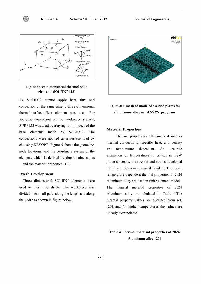
Fig. 6: three dimensional thermal solid elements SOLID70 [18]
As SOLID70 cannot apply heat flux and
convection at the same time, a three-dimensional
thermal-surface-effect element was used. For
applying convection on the workpiece surface,
SURF152 was used overlaying it onto faces of the
base elements made by SOLID70. The
convections were applied as a surface load by
choosing KEYOPT. Figure 6 shows the geometry,
node locations, and the coordinate system of the
element, which is defined by four to nine nodes
and the material properties [18].
Mesh Development
Three dimensional SOLID70 elements were
used to mesh the sheets. The workpiece was
divided into small parts along the length and along
the width as shown in figure below.
Fig. 7: 3D mesh of modeled welded plates for
aluminume alloy in ANSYS program
Material Properties
Thermal properties of the material such as
thermal conductivity, specific heat, and density
are temperature dependent. An accurate
estimation of temperatures is critical in FSW
process because the stresses and strains developed
in the weld are temperature dependent. Therefore,
temperature dependent thermal properties of 2024
Aluminum alloy are used in finite element model.
The thermal material properties of 2024
Aluminum alloy are tabulated in Table 4.The
thermal property values are obtained from ref.
[20], and for higher temperatures the values are
linearly extrapolated.
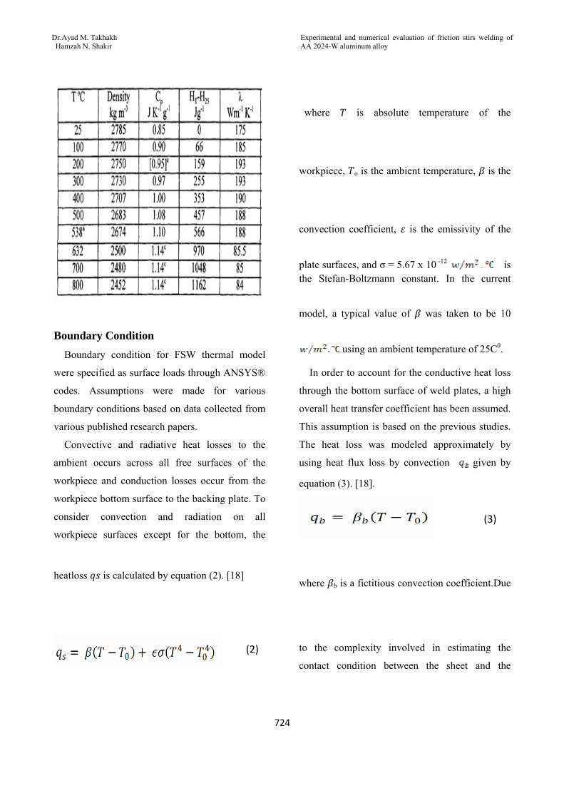
Table 4 Thermal material properties of 2024
Aluminum alloy.[20]
Experimental and numerical evaluation of friction stirs welding of AA 2024-W aluminum alloy
Dr.Ayad M. Takhakh Hamzah N. Shakir
724
Boundary Condition
Boundary condition for FSW thermal model
were specified as surface loads through ANSYS®
codes. Assumptions were made for various
boundary conditions based on data collected from
various published research papers.
Convective and radiative heat losses to the
ambient occurs across all free surfaces of the
workpiece and conduction losses occur from the
workpiece bottom surface to the backing plate. To
consider convection and radiation on all
workpiece surfaces except for the bottom, the
heatloss is calculated by equation (2). [18]
where is absolute temperature of the
workpiece, o is the ambient temperature, is the
convection coefficient, is the emissivity of the
plate surfaces, and σ = 5.67 x 10 -12 is the Stefan-Boltzmann constant. In the current
model, a typical value of was taken to be 10
using an ambient temperature of 25C0.
In order to account for the conductive heat loss
through the bottom surface of weld plates, a high
overall heat transfer coefficient has been assumed.
This assumption is based on the previous studies.
The heat loss was modeled approximately by
using heat flux loss by convection given by
equation (3). [18].
where b is a fictitious convection coefficient.Due
to the complexity involved in estimating the
contact condition between the sheet and the
(3)
(2)
ج
Journal of Engineering Volume 18 June 2012 Number 6
725
backing plate, the value of b had to be estimated
by assuming different values through reverse
analysis approach. In this study, the optimized
value of b was found to be 100 [18
.
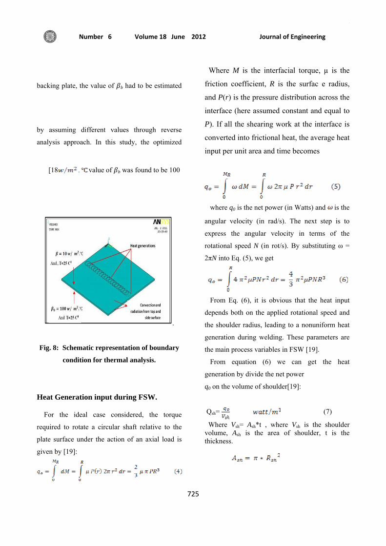
Fig. 8: Schematic representation of boundary
condition for thermal analysis.
Heat Generation input during FSW.
For the ideal case considered, the torque
required to rotate a circular shaft relative to the
plate surface under the action of an axial load is
given by [19]:
Where M is the interfacial torque, µ is the
friction coefficient, R is the surfac e radius,
and P(r) is the pressure distribution across the
interface (here assumed constant and equal to
P). If all the shearing work at the interface is
converted into frictional heat, the average heat
input per unit area and time becomes
where q0 is the net power (in Watts) and is the
angular velocity (in rad/s). The next step is to
express the angular velocity in terms of the
rotational speed N (in rot/s). By substituting ω =
2πN into Eq. (5), we get
From Eq. (6), it is obvious that the heat input
depends both on the applied rotational speed and
the shoulder radius, leading to a nonuniform heat
generation during welding. These parameters are
the main process variables in FSW [19].
From equation (6) we can get the heat
generation by divide the net power
q0 on the volume of shoulder[19]:
Qsh= (7)
Where Vsh= Ash*t , where Vsh is the shoulder volume, Ash is the area of shoulder, t is the thickness.
Experimental and numerical evaluation of friction stirs welding of AA 2024-W aluminum alloy
Dr.Ayad M. Takhakh Hamzah N. Shakir
726
Where the coefficient of friction of aluminum is
0.4 [19 , 21], this value is changed and dropped
gradually in friction stir welding because the
coefficient of friction µ varies with temperature
and reached to 0.3 [22].where The temperature
measurement in FSW for the workpiece was
reported that the maximum temperature developed
during FSW process ranges from 80% to 90%
from melting temperature of the welding material
[20].
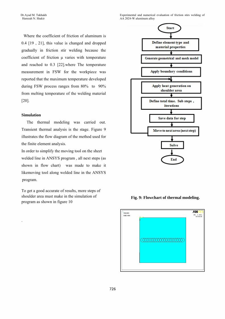
Simulation
The thermal modeling was carried out.
Transient thermal analysis is the stage. Figure 9
illustrates the flow diagram of the method used for
the finite element analysis.
In order to simplify the moving tool on the sheet
welded line in ANSYS program , all next steps (as
shown in flow chart) was made to make it
likemoving tool along welded line in the ANSYS
program.
To get a good accurate of results, more steps of shoulder area must make in the simulation of program as shown in figure 10
.
Fig. 9: Flowchart of thermal modeling.

ج
Journal of Engineering Volume 18 June 2012 Number 6
727
Figure 10: steps of circular shoulder area along welded line.
here each shoulder circle has heat generation and
time step, also each circle represents one step.
Heat input (heat generation) is estimated by trial
and error from ANSYS program because applied
pressure P from equation 4 is unknown.
The method of heat input calculation by trial and
error found by take the data (temperature and
time) of thermocouple readings for one point (for
example A in fig. 11) where in these data we
depend on maximum temperature and make the
following steps:
1- Assumed high value of heat generation where
this value entered in program to make
simulation for aluminum plate to get the
maximum temperature at point A.
2- Assume low value of heat generation and
examined it in program by make simulation
for the aluminum plate at point A to get
maximum temperature for these low value of
heat generation.
3- Applying the interpolation on these (three
values of temperature and two values of heat
generation ) to get a good agreement heat for
this work .
After get good agreement heat generation,
applying it in other steps of program.
From the validation shows that the present
work can be used for modeling thermal
distribution.
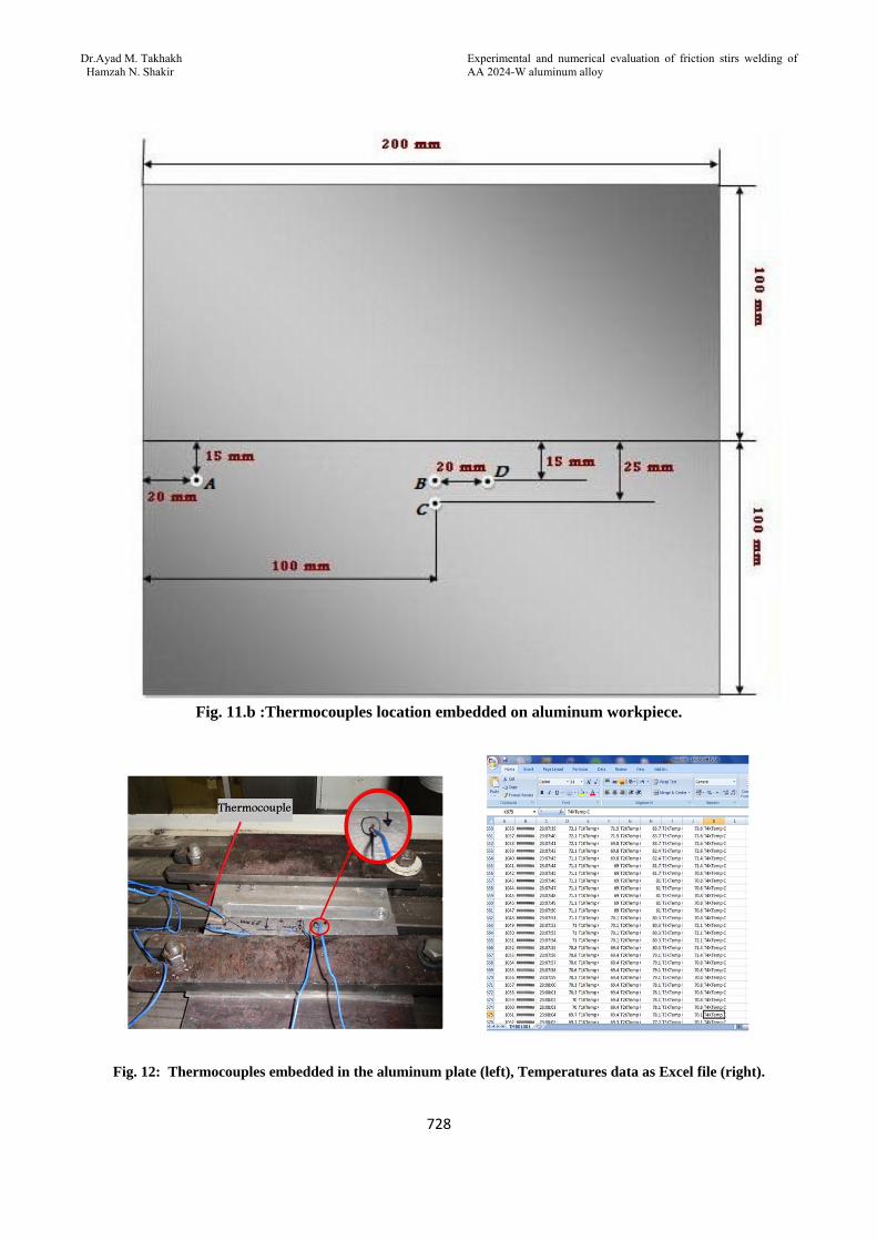
Four K-type thermocouples at selected points of
aluminum sheet as shown in figure 11 have been
used for measuring the temperature distribution
by using temperature recorder type BTM-4208SD
which contains 12 channels as shown in figure 11
(a &b) when these four thermocouples have been
embedded in selected positions to 1.5 mm on the
aluminum sheet as shown in figure (12 left) where
recorded data temperatures changed with time are
saved as excel file in the RAM of temperature
recorder as shown in figure (12. right).
Fig. 11.a , Temperature recorder
Experimental and numerical evaluation of friction stirs welding of AA 2024-W aluminum alloy
Dr.Ayad M. Takhakh Hamzah N. Shakir
728
Fig. 11.b :Thermocouples location embedded on aluminum workpiece.
Fig. 12: Thermocouples embedded in the aluminum plate (left), Temperatures data as Excel file (right).
ج
Journal of Engineering Volume 18 June 2012 Number 6
729
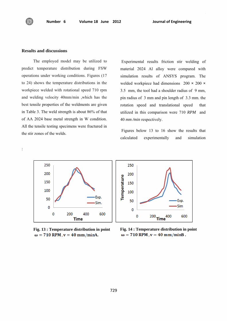
Results and discussions
The employed model may be utilized to
predict temperature distribution during FSW
operations under working conditions. Figures (17
to 24) shows the temperature distributions in the
workpiece welded with rotational speed 710 rpm
and welding velocity 40mm/min ,which has the
best tensile properties of the weldments are given
in Table 3. The weld strength is about 86% of that
of AA 2024 base metal strength in W condition.
All the tensile testing specimens were fractured in
the stir zones of the welds.
Experimental results friction stir welding of
material 2024 Al alloy were compared with
simulation results of ANSYS program. The
welded workpiece had dimensions 200 × 200 ×
3.5 mm, the tool had a shoulder radius of 9 mm,
pin radius of 3 mm and pin length of 3.3 mm. the
rotation speed and translational speed that
utilized in this comparison were 710 RPM and
40 mm /min respectively.
Figures below 13 to 16 show the results that
calculated experimentally and simulation
:
Fig. 13 : Temperature distribution in point
A. Fig. 14 : Temperature distribution in point
B .

Experimental and numerical evaluation of friction stirs welding of AA 2024-W aluminum alloy
Dr.Ayad M. Takhakh Hamzah N. Shakir
730
The modeling of this work is solved and the
temperature distribution obtained for the model
and the result show that there is good agreement
between present work and ANSYS result. The
difference in results of temperature distribution
between experimental examination and modeling
ranged between 5 – 14% which its acceptance.
Figures 17 to 24 show the maximum temperature
of welding plate which has been reached at
several time steps:
:
Fig. 15: Temperature distribution in point C.
Fig. 16 : Temperature distribution in point D.
Fig. 17: Temperature distribution at 10 s, Max. Temp. 35 C0
Fig. 18 :Temperature distribution at 100 s, Max. Temp. 123 C0

ج
Journal of Engineering Volume 18 June 2012 Number 6
731
Fig. 19 :Temperature distribution at 300 s, Max. Temp. 365 C0
Fig. 20 :Temperature distribution at 400 s, Max. Temp. 336 C0
Fig. 21:Temperature distribution at 435 s, Max. Temp. 360 C0
Fig. 22:Temperature distribution at 536 s, Max. Temp. 444 C0
Fig. 23 : Temperature distribution at 550 s, Max. Temp. 197 C0
Fig. 24 : Temperature distribution at 600 s, Max. Temp. 94 C0
Experimental and numerical evaluation of friction stirs welding of AA 2024-W aluminum alloy
Dr.Ayad M. Takhakh Hamzah N. Shakir
732
As it is seen, temperature gradient increases
in front of the tool comparing to its backside, i.e.,
the temperature profile extends further towards
the welded region behind the moving tool.
Because of shoulder rotation, the material flow
near the top surface is accelerated, and therefore,
material deformation on the top surface next to the
contact region is higher than the region at the
bottom side. The material deformation has an
important role on the formation of the weld zone
profile in FSW operations [23].
The predicted maximum temperature is 444 C0 in
the region under the shoulder on the top surface.
This temperature is about 58 C0 below the solidus
temperature of Al 2024 and is within accepted
temperature range in FSW process.
Figures 13 to 16 shows the thermal cycles in the
various points of sample No.6 at the depth of 1.5
mm. It can be seen that heating rate is higher than
the corresponding cooling rate to room
temperature.
As expected, the peak temperatures are higher at
locations close to the weld line, and it decreases
toward the HAZ.
Conclusion
1- Variation of the nugget-zone temperature with
respect to time.
2- The temperature decreases with distance
perpendicular direction of the tool on the top
surface.
3- The variation of peak temperature with respect
to thermal conductivity, specific heat and
density is obtained.
4- Comparison of temperature profile developed
between simulation values and the experimental
results showed the possibility of more accurate
determination using present simulation.
REFERENCES
1. M. Awang, et. al. “Experience on
Friction Stir Welding and Friction Stir
Spot Welding at Universiti teknologi
petronas”, journal of applied sience
11(2011):pp.1959-1965.
2. M. Vural, et. al. “On the Friction Stir
Welding of Aluminium alloys EN AW
2024-0 and EN AW 5754-H22”, Archives
of Materials Science and Engineering,
Volume 28, Issue 1,(2007),pp.49-54.
3. S. Rajakumar, et. al. “Statistical
Analysis to Predict Grain Size and
Hardness of the Weld Nugget of Friction-
Stir-Welded AA6061-T6 aluminium alloy
joints”, Int J Adv Manuf Technol (2011)
57:151–165, DOI 10.1007/s00170-011-
3279-5.
4. Kevin Deplus, et. al. “Residual Stresses
in Aluminium Alloy Friction Stir Weld”,
Int J Adv Manuf Technol (2011) 56:
pp.493–504.
ج
Journal of Engineering Volume 18 June 2012 Number 6
733
5. Ciro Bitondo, et. al. “Friction-Stir
Welding of AA 2198 butt joints:
Mechanical Characterization of The
Process and of The Welds Through DOE
Analysis”, Int J Adv Manuf Technol
(2011) 53:pp.505–516.
6. Mohammad Riahi & Hamidreza
Nazari “Analysis of Transient
Temperature and Residual Thermal
Stresses in Friction Stir Welding of
Aluminum Alloy 6061-T6 via Numerical
Simulation”, Int J Adv Manuf Technol
(2011) 55:pp.143–152.
7. Dong-yang Yan, et. al. “Predicting
Residual Distortion of Aluminum Alloy
Stiffened Sheet After Friction Stir
Welding by Numerical Simulation”,
Materials and Design 32 (2011)pp. 2284–
2291.
8. P. Prasanna, et. al. “Experimental and
Numerical Evaluation of Friction Stirs
Welding of AA 6061 –T6 Aluminum
alloy”, ARPN Journal of Engineering and
Applied Sciences, VOL. 5, NO. 6,(2010).
9. P. Prasanna, et. al. “Finite Element
Modeling for Maximum Temperature in
Friction Stir Welding And Its Validation”,
Int J Adv Manuf Technol (2010)
51:pp.925–933.
10. S. Mandal, et. al. “The Effect of The
Alclad Layer on Material Flow and
Defect Formation During Friction-stir
Welding”, Metallurgical and Materials
Transactions, Volume 42, Issue
6,(2011),pp.1717-1726.
11. H. Jamshidi Aval, et. al. “Experimental
and Theoretical Valuations of Thermal
Histories and Residual Stresses in
Dissimilar Friction Stir Welding of
AA5086-AA6061”, Int J Adv Manuf
Technol, (2011), DOI 10.1007/s00170-
011-3713-8.
12. H. Jamshidi Aval, et. al. “Evolution of
Microstructures and Mechanical
Properties in Similar and Dissimilar
Friction Stir Welding of AA5086 and
AA6061”, Materials Science and
Engineering, Volume 528, Issue 28,
pp.8071- 8083 (2011).
13. Z. Zhang, et. al. “Coupled Thermo-
Mechanical Model Based Comparison of
Friction Stir Welding Processes of
AA2024-T3 in Different Thicknesses”, J
Mater Sci (2011) 46: pp5815–5821, DOI
10.1007/s10853-011-5537-1.
14. Mohamed Assidi and Lionel
Fourment “Accurate 3d friction stir
Welding Simulation Tool Based on
Friction Model Calibration”, Int J Mater
Form Vol. 2 (2009) 1:327–330.
15. G. Buffa, et. al. “A new Friction Stir
Welding Based Technique for Corner
Fillet Joints: Experimental and Numerical
Study”, Int J Mater Form Vol. 3 (2010)
1:pp.1039 – 1042.

Experimental and numerical evaluation of friction stirs welding of AA 2024-W aluminum alloy
Dr.Ayad M. Takhakh Hamzah N. Shakir
734
16. Z. Zhang & H. W. Zhang “Material
Behaviors and Mechanical Features in
Friction Stir Welding Process”, Int J Adv
Manuf Technol (2007) 35:pp.86–100.
17. R. Palanivel, et. al. “Development of
Mathematical Model to Predict the
Mechanical Properties of Friction Stir
Welded AA6351 Aluminum Alloy”,
Journal of Engineering Science and
Technology Review 4 (1) (2011)pp. 25-
31.
18. Manthan Malde " Thermomechanical
Modeling and Optimization of Friction
Stir Welding" , B.E., Osmania
University, Hyderabad, India,( 2009).
19. Ø. FRIGAARD, et. Al. "A Process
Model for Friction Stir Welding of Age
Hardening Aluminum Alloys",
Metallurgical and Materials Transactions
a volume 32a, (2001), 1189-1200.
20. Kenneth C Mills "Recommended
Values of Thermophysical Properties for
Selected Commercial Alloys ", The
Materials Information Society ASM,
(2005).
21. Vijay Soundararajan, et. al. "
Thermo-Mechanical Model With
Adaptive Boundary Conditions for
Friction Stir Welding of Al 6061",
International Journal of Machine Tools &
Manufacture 45 (2005) pp.1577–1587.
22. R. Nandan, et. al."Three-dimensional
Heat and Material Flow During Friction
Stir Welding of Mild Steel ", Acta
Materialia 55 (2007)pp. 883–895.
23. H. Jamshidi Aval, et. al. ”Theoretical
and Experimental Investigation into
Friction Stir Welding of AA 5086”, Int J
Adv Manuf Technol (2011) 52: pp.531–
544.
24. Myer Kutz "Mechanical Engineering
Handbook", Third edition, Material and
Mechanical design, (2006).
25. Hakan Aydin , et. al."Tensile Properties
of Friction Stir Welded Joints of 2024
Alluminume Alloy in Different Heat
Treated State", J Master design,
doi:10.1016/j.matdes. (2008).08.034


![CURRICULUM VITAElished a research paper [127] in my publication list. In collaboration with R. MONTALVO and Prof. Rajpoot, I have also published a research paper [136] in my publication](https://static.fdocuments.in/doc/165x107/5e8cdfce19e4a639a20e1bf9/curriculum-lished-a-research-paper-127-in-my-publication-list-in-collaboration.jpg)