MY - Farnell element14 | Electronic Component … · General-purpose Relay MY 281 General-purpose...
20
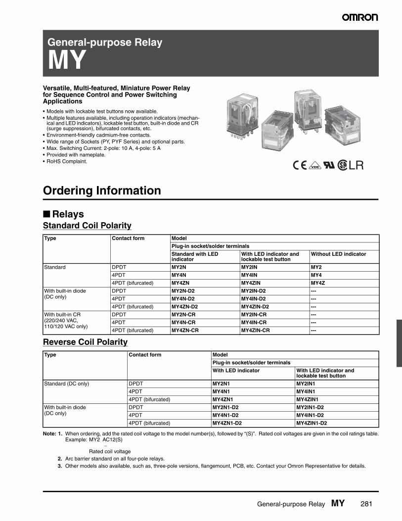
General-purpose Relay MY 281 General-purpose Relay MY Versatile, Multi-featured, Miniature Power Relay for Sequence Control and Power Switching Applications • Models with lockable test buttons now available. • Multiple features available, including operation indicators (mechan- ical and LED indicators), lockable test button, built-in diode and CR (surge suppression), bifurcated contacts, etc. • Environment-friendly cadmium-free contacts. • Wide range of Sockets (PY, PYF Series) and optional parts. • Max. Switching Current: 2-pole: 10 A, 4-pole: 5 A • Provided with nameplate. • RoHS Complaint. LR Ordering Information ■ Relays Standard Coil Polarity Reverse Coil Polarity Note: 1. When ordering, add the rated coil voltage to the model number(s), followed by “(S)”. Rated coil voltages are given in the coil ratings table. Example: MY2 AC12(S) − Rated coil voltage 2. Arc barrier standard on all four-pole relays. 3. Other models also available, such as, three-pole versions, flangemount, PCB, etc. Contact your Omron Representative for details. Type Contact form Model Plug-in socket/solder terminals Standard with LED indicator With LED indicator and lockable test button Without LED indicator Standard DPDT MY2N MY2IN MY2 4PDT MY4N MY4IN MY4 4PDT (bifurcated) MY4ZN MY4ZIN MY4Z With built-in diode (DC only) DPDT MY2N-D2 MY2IN-D2 --- 4PDT MY4N-D2 MY4IN-D2 --- 4PDT (bifurcated) MY4ZN-D2 MY4ZIN-D2 --- With built-in CR (220/240 VAC, 110/120 VAC only) DPDT MY2N-CR MY2IN-CR --- 4PDT MY4N-CR MY4IN-CR --- 4PDT (bifurcated) MY4ZN-CR MY4ZIN-CR --- Type Contact form Model Plug-in socket/solder terminals With LED indicator With LED indicator and lockable test button Standard (DC only) DPDT MY2N1 MY2IN1 4PDT MY4N1 MY4IN1 4PDT (bifurcated) MY4ZN1 MY4ZIN1 With built-in diode (DC only) DPDT MY2N1-D2 MY2IN1-D2 4PDT MY4N1-D2 MY4IN1-D2 4PDT (bifurcated) MY4ZN1-D2 MY4ZIN1-D2
Transcript of MY - Farnell element14 | Electronic Component … · General-purpose Relay MY 281 General-purpose...
General-purpose Relay MY 281
General-purpose Relay
MYVersatile, Multi-featured, Miniature Power Relay for Sequence Control and Power Switching Applications• Models with lockable test buttons now available.• Multiple features available, including operation indicators (mechan-
ical and LED indicators), lockable test button, built-in diode and CR (surge suppression), bifurcated contacts, etc.
• Environment-friendly cadmium-free contacts.• Wide range of Sockets (PY, PYF Series) and optional parts.• Max. Switching Current: 2-pole: 10 A, 4-pole: 5 A• Provided with nameplate.• RoHS Complaint. LR
Ordering Information
■ RelaysStandard Coil Polarity
Reverse Coil Polarity
Note: 1. When ordering, add the rated coil voltage to the model number(s), followed by “(S)”. Rated coil voltages are given in the coil ratings table.Example: MY2 AC12(S)
−Rated coil voltage
2. Arc barrier standard on all four-pole relays.3. Other models also available, such as, three-pole versions, flangemount, PCB, etc. Contact your Omron Representative for details.
Type Contact form Model
Plug-in socket/solder terminals
Standard with LED indicator
With LED indicator and lockable test button
Without LED indicator
Standard DPDT MY2N MY2IN MY2
4PDT MY4N MY4IN MY4
4PDT (bifurcated) MY4ZN MY4ZIN MY4Z
With built-in diode (DC only)
DPDT MY2N-D2 MY2IN-D2 ---
4PDT MY4N-D2 MY4IN-D2 ---
4PDT (bifurcated) MY4ZN-D2 MY4ZIN-D2 ---
With built-in CR (220/240 VAC, 110/120 VAC only)
DPDT MY2N-CR MY2IN-CR ---
4PDT MY4N-CR MY4IN-CR ---
4PDT (bifurcated) MY4ZN-CR MY4ZIN-CR ---
Type Contact form Model
Plug-in socket/solder terminals
With LED indicator With LED indicator and lockable test button
Standard (DC only) DPDT MY2N1 MY2IN1
4PDT MY4N1 MY4IN1
4PDT (bifurcated) MY4ZN1 MY4ZIN1
With built-in diode (DC only)
DPDT MY2N1-D2 MY2IN1-D2
4PDT MY4N1-D2 MY4IN1-D2
4PDT (bifurcated) MY4ZN1-D2 MY4ZIN1-D2

282 General-purpose Relay MY
Specifications
■ Coil Ratings
Note: 1. The rated current and coil resistance are measured at a coil temperature of 23°C with tolerances of +15%/–20% for rated currents and±15% for DC coil resistance.
2. Performance characteristic data are measured at a coil temperature of 23°C.3. AC coil resistance and impedance are provided as reference values (at 60 Hz).4. Power consumption drop was measured for the above data. When driving transistors, check leakage current and connect a bleeder re-
sistor if required.5. Rated voltage denoted by “*” will be manufactured upon request. Ask your OMRON representative.
■ Contact Ratings
* Reference value.
Note: Do not exceed the carry current of a Socket in use.
Rated voltage Rated current Coil resistance
Inductance (reference value)
Must operate
Must release
Max. voltage
Power consumption (approx.)50 Hz 60 Hz Arm. OFF Arm. ON % of rated voltage
AC 6 V* 214.1 mA 183 mA 12.2 Ω 0.04 H 0.08 H 80% max. 30% min. 110% 1.0 to 1.2 VA (60 Hz)12 V 106.5 mA 91 mA 46 Ω 0.17 H 0.33 H
24 V 53.8 mA 46 mA 180 Ω 0.69 H 1.30 H
48/50 V* 24.7/25.7 mA
21.1/22.0 mA
788 Ω 3.22 H 5.66 H
110/120 V 9.9/10.8 mA 8.4/9.2 mA 4,430 Ω 19.20 H 32.1 H 0.9 to 1.1 VA (60 Hz)
220/240 V 4.8/5.3 mA 4.2/4.6 mA 18,790 Ω 83.50 H 136.4 H
DC 6 V* 151 mA 39.8 Ω 0.17 H 0.33 H 10% min. 0.9 W
12 V 75 mA 160 Ω 0.73 H 1.37 H
24 V 37.7 mA 636 Ω 3.20 H 5.72 H
48 V* 18.8 mA 2,560 Ω 10.60 H 21.0 H
100/110 V 9.0/9.9 mA 11,100 Ω 45.60 H 86.2 H
Item 2-pole 4-pole 4-pole (bifurcated)
Resistive load (cosφ = 1)
Inductive load (cosφ = 0.4, L/R = 7 ms)
Resistive load (cosφ = 1)
Inductive load (cosφ = 0.4, L/R = 7 ms)
Resistive load (cosφ = 1)
Inductive load (cosφ = 0.4, L/R = 7 ms)
Rated load 5 A, 250 VAC5 A, 30 VDC
2 A, 250 VAC2 A, 30 VDC
3 A, 250 VAC3 A, 30 VDC
0.8 A, 250 VAC1.5 A, 30 VDC
3 A, 250 VAC3 A, 30 VDC
0.8 A, 250 VAC1.5 A, 30 VDC
Carry current 10 A (see note) 5 A (see note)
Max. switching voltage
250 VAC125 VDC
250 VAC125 VDC
Max. switching current
10 A 5 A
Max. switching capacity
2,500 VA300 W
1,250 VA300 W
1,250 VA150 W
500 VA150 W
1,250 VA150 W
500 VA150 W
Min. permissible load*
5 VDC, 1 mA 1 VDC, 1 mA 1 VDC, 100 μA

General-purpose Relay MY 283
■ Characteristics
Note: The values given above are initial values.
■ Life Expectancy Characteristics
■ Approved StandardsVDE, UL, CSA, CE(CE marking is provided only on non-PCB terminal versions)
■ Precautions
ConnectionsDo not reverse polarity when connecting DC-operated Relays withbuilt-in diodes or indicators or high-sensitivity DC-operated Relays.
MountingWhenever possible, mount Relays so that it is not subject to vibrationor shock in the same direction as that of contact movement.
Contact resistance 100 mΩ max.
Operate time 20 ms max.
Release time 20 ms max.
Max. operating frequency Mechanical 18,000 operations/hr
Electrical 1,800 operations/hr (under rated load)
Insulation resistance 1,000 MΩ min. (at 500 VDC)
Dielectric withstand voltage 2,000 VAC, 50/60 Hz for 1.0 min (1,000 VAC between contacts of same polarity)
Vibration resistance Destruction:10 to 55 Hz, 1.0 mm double amplitudeMalfunction:10 to 55 Hz, 1.0 mm double amplitude
Shock resistance Destruction:1,000 m/s2 (approx. 100G) Malfunction:200 m/s2 (approx. 20G)
Life expectancy See the following table.
Ambient temperature Operating -55°C to 70°C (-67°F to 158°F) with no icing (see note)
Ambient humidity Operating 5% to 85% RH
Weight Approx. 35 g
Pole Mechanical life (at 18,000 operations/hr)
Electrical life (at 1,800 operations/hr under rated load)
2-pole AC:50,000,000 operations min.DC:100,000,000 operations min.
500,000 operations min.
4-pole 200,000 operations min.
4-pole (bifurcated) 20,000,000 operations min. 100,000 operations min.

284 General-purpose Relay MY
Engineering Data
■ Maximum Switching Power
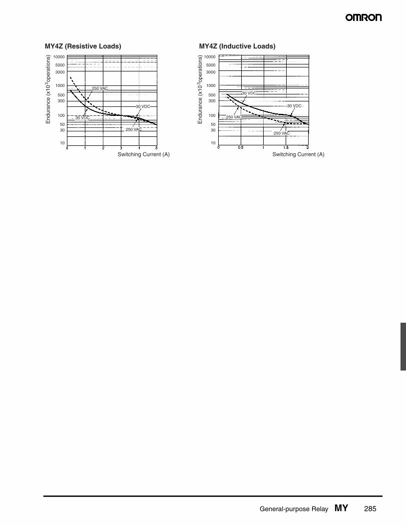
■ Endurance
MY2 MY4, MY4Z
Sw
itchi
ng c
urre
nt (
A)
AC resistive load
DC resistive load
AC resistive load
DC resistive load
Sw
itchi
ng c
urre
nt (
A)
Switching voltage (V) Switching voltage (V)
AC inductive load (cosφ=0.4)
DC inductive load (L/R=7 ms)
AC inductive load (cosφ=0.4)
DC inductive load (L/R=7 ms)
10000
5000
3000
1000
500300
100
5030
10
10000
5000
3000
1000
500300
100
5030
10
MY2 (Resistive Loads) MY2 (Inductive Loads)
End
uran
ce (
x10
ope
ratio
ns)
3
Switching current (A)
250 VAC
30 VDC30 VDC
250 VAC
End
uran
ce (
x10
ope
ratio
ns)
3
Switching current (A)
30 VDC
250 VAC
250 VAC
30 VDC
10000
5000
3000
1000
500300
100
5030
10
10000
5000
3000
1000
500300
100
5030
10
MY4 (Resistive Loads) MY4 (Inductive Loads)
End
uran
ce (
x10
ope
ratio
ns)
3
Switching current (A)
250 VAC
30 VDC
30 VDC
250 VAC End
uran
ce (
x10
ope
ratio
ns)
3
Switching current (A)
30 VDC
250 VAC
250 VAC
30 VDC
General-purpose Relay MY 285
10000
5000
3000
1000
500300
100
5030
10
10000
5000
3000
1000
500300
100
5030
10
MY4Z (Resistive Loads) MY4Z (Inductive Loads)E
ndur
ance
(x1
0 o
pera
tions
)3
Switching Current (A)
250 VAC
30 VDC
250 VAC
30 VDC
250 VAC
250 VAC
30 VDC
30 VDC
End
uran
ce (
x10
ope
ratio
ns)
3
Switching Current (A)
286 General-purpose Relay MY
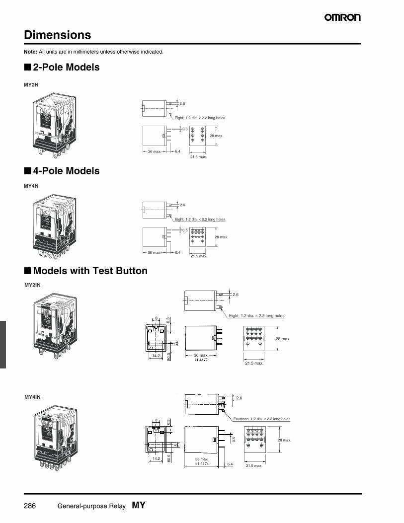
DimensionsNote: All units are in millimeters unless otherwise indicated.
■ 2-Pole Models
■ 4-Pole Models
■ Models with Test Button
0.5
6.4
MY2N
21.5 max.36 max.
28 max.
2.6
Eight, 1.2 dia. × 2.2 long holes
0.5
21.5 max.36 max. 6.4
MY4N
28 max.
2.6
Eight, 1.2 dia. × 2.2 long holes
36 max.
MY2IN
8
14.2
5
80.5
6.3
2.6
Eight, 1.2 dia. × 2.2 long holes
21.5 max.
28 max.
MY4IN
36 max.<1.417>
Fourteen, 1.2 dia. × 2.2 long holes
0.5
80.5
6.3
5
6.4
14.2
8
2.6
21.5 max.
28 max.

General-purpose Relay MY 287
■ Terminal Arrangement/Internal Connections (Bottom View)
MY2 MY2N/MY2IN(AC Models)
MY2N/MY2IN(DC Models)
MY2N-D2/MY2IN-D2(DC Models Only)
MY2N-CR/MY2IN-CR(AC Models Only)
MY2N1/MY2IN1(DC Models Only)
MY2N1-D2/MY2IN1-D2(DC Models Only)
MY4(Z)N-CR/MY4(Z)IN-CR(AC Models Only)
MY4(Z)N1/MY4(Z)IN1(DC Models Only)
MY4(Z)N1-D2/MY4(Z)N1-D2(DC Models Only)
MY4(Z) MY4(Z)N/MY4(Z)IN(AC Models)
MY4(Z)N/MY4(Z)IN(DC Models)
MY4(Z)N-D/MY4(Z)IN-D2(DC Models Only)

288 General-purpose Relay MY
Accessories (order separately)
■ Track-mounted Screwless Clamp Terminal Sockets
Note: For complete specifications, see the datasheet at Omron's Knowledge Center on our website: www.knowledge.omron.com.
■ Sockets
■ Socket Specifications
Note: 1. The values given above are initial values.2. The values for insulation resistance were measured at 500 V at the same place as the dielectric strength.3. The maximum operating ambient temperature for the PYF08A-N and PYF14A-N is 55°C. 4. When using the PYF08A-N or PYF14A-N at an operating ambient temperature exceeding 40°C, reduce the current to 60%.5. The MY2(S) can be used at 70°C with a carry current of 7 A.
■ Socket Hold-down Clip Pairing
Item Model
4-pole 2-pole
Socket PYF14S PYF08S
Clip & release lever PYCM-14S PYCM-08S
Nameplate R99-11 Nameplate for MY
Socket bridge PYDM-14SR PYDM-14SB PYDM-08SR PYDM-08SB
Poles Front-connecting socket (DIN-track/screw mounting)
Back-connecting socket
Solder terminals PCB terminals
Without clip With clip
2 PYF08A-E PY08 PY08-Y1 PY08-02
PYF08A-N
4 PYF14A-E PY14 PY14-Y1 PY14-02
PYF14A-N
Item Pole Model Carry current Dielectric withstand voltage
Insulation resistance (see note 2)
Screwless clamp terminal socket
2 PYF08S 10 A 2,000 VAC, 1 min Less than 1,000 MΩ4 PYF14S 5 A
Track-mounted socket
2 PYF08A-E 7 A 2,000 VAC, 1 min 1,000 MΩ min.
PYF08A-N (see note 3) 7 A (see note 4)
4 PYF14A-E 5 A
PYF14A-N (see note 3) 5 A (see note 4)
Back-connecting socket
2 PY08(-Y1) 7 A 1,500 VAC, 1 min 100 MΩ min.
PY08-02
4 PY14(-Y1) 3 A
PY14-02
Relay type Poles Front-connecting socket (DIN-track/screw mounting)
Back-connecting socket
Solder terminals PCB terminals
Socket Clip Socket Clip Socket Clip
Without 2-pole test button
2 PYF08A-E PYC-A1 PY08 PYC-PPYC-P2
PY08-02 PYC-PPYC-P2PYF08A-N
Without 2-pole test button
4 PYF14A-E PYC-A1 PY14 PYC-PPYC-P2
PY14-02 PYC-PPYC-P2PYF14A-N
2-pole test but-ton
2 PYF08A-E PYC-E1 PY08 PYC-P2 PY08-02 PYC-P2
PYF08A-N

General-purpose Relay MY 289
■ Mounting Plates for Sockets
Note: PYP-18 and PYP-36 can be cut into any desired length in accordance with the number of Sockets.
■ DIN Rail Track and Accessories
Socket model For 1 socket For 18 sockets For 36 sockets
PY08, PY14 PYP-1 PYP-18 PYP-36
Description Model
Mounting rail (length = 500 mm) PFP-50N
Mounting rail (length = 1,000 mm) PFP-100N, PFP-100N2
End Plate PFP-M
Spacer PFP-S

290 General-purpose Relay MY
■ DimensionsUnit: mm (inch)
Socket Dimensions Terminal arrangement/internal connections (top view)
Mounting holes
PYF08A-E
31 max.
23 max.
72 max.
Two, 4.2 x 5 mounting holes
Eight, M3 x 8 sems screws
(TOP VIEW)
Two, M3, M4, or 4.5-dia. holes
Note: Track mounting is also possible. Refer to page 12 for supporting tracks.
PYF14A-E
31 max.
29.5 max.
72 max.
Two, 4.2 x 5 mounting holes Fourteen, M3 x 8
sems screws
(TOP VIEW)
Two, M3, M4, or 4.5-dia. holes
Note: Track mounting is also possible. Refer to page 12 for supporting tracks.
PY08/PY08-Y1 (See note) Eight, 3 x 1.2 elliptical holes
25.5 max.29.5 max.
24 max.42 max.
Note: The PY08-Y1 includes sections indicated by dotted lines.
20 max.
PY08-02
16.5 max.
22 max.
25.5 max.29.5 max.
Eight, 1.3-dia. holes
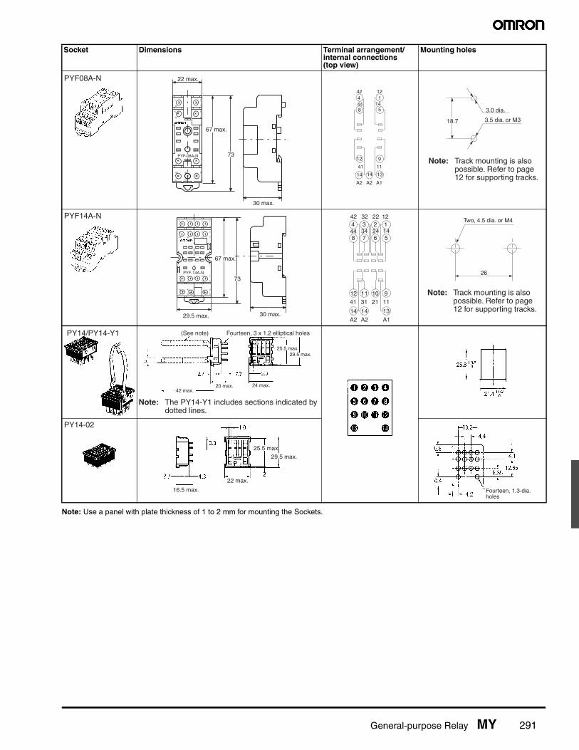
General-purpose Relay MY 291
Note: Use a panel with plate thickness of 1 to 2 mm for mounting the Sockets.
Socket Dimensions Terminal arrangement/internal connections (top view)
Mounting holes
PYF08A-N
4
42
8
44
1
12
5
14
41
12
A2
14
11
9
A1
13
A2
14
PYF-08A-N 73
22 max.
67 max.
30 max.
442
1
8 5
12 9
14 14 13
44
12
14
41 11
A2 A2 A1
18.7
3.0 dia.
3.5 dia. or M3
Note: Track mounting is also possible. Refer to page 12 for supporting tracks.
PYF14A-N4
42
3
32
2
22
1
12
8
44
7
34
6
24
5
14
41
12
31
11
21
10
11
9
A1
13
A2
14
A2
14
PYF-14A-N
73
30 max.
67 max.
29.5 max.
4 3 2 1
8 7 6 5
12 11 10 9
14 14 13
42 32 22 12
44 34 24 14
41 31 21 11
A2 A2 A1
26
Two, 4.5 dia. or M4
Note: Track mounting is also possible. Refer to page 12 for supporting tracks.
PY14/PY14-Y1 (See note) Fourteen, 3 x 1.2 elliptical holes
25.5 max.29.5 max.
24 max.42 max.
Note: The PY14-Y1 includes sections indicated by dotted lines.
20 max.
PY14-02
16.5 max.
22 max.
25.5 max.29.5 max.
Fourteen, 1.3-dia. holes

292 General-purpose Relay MY
Socket Bridge
Note: 1. The relationship between the model number, the length L,and the color of the insulating coating is shown above.
2. The insulating coating must be able to withstand a voltageof 1,500 V for 1 minute. Use either PE or PA as the materialof the insulating coating.
3. The positions of the ends of the insulating coating must notvary more than 0.5 mm.
4. The characteristics of the socket bridge are shown above.
Socket Dimensions Terminal arrangement/internal connections (top view)
Mounting height (with lever)
Note: Pole-2 and pole-3 can-not be used with theMY2 type. Use pole-1(terminal numbers 11,14, 12) and pole-4(terminal numbers41, 44, 42).
Note: Track mounting only.
Note: Track mounting only.
PYF14S 36.5 max.
31 max.
85 max.
72.6 typ.
28.6
PYF08S
(5.3)
85 max.
38.2 max.36.5 max.
23.2 max. 73.6 typ.
28.6
Insulating coating
1.4 dia. conductorL
(See note 1.)
Model number Length L (mm) Color of insulating coating
PYDM-14SR 27.5±0.3 Red
PYDM-14SB Blue
PYDM-08SR 19.7±0.3 Red
PYDM-08SB Blue
Item Characteristic
Rated ON current 10 A
Rated insulation voltage 250 VAC
Temperature rise 35°C max.
Dielectric strength 1,500 VAC for 1 minute
Ambient operating temperature -55 to 70°C

General-purpose Relay MY 293
■ Clip and Release Levers
■ Hold-down Clips
PYF14S Lever PYF08S Lever
26.5 typ.28 typ.
52.5 typ.
3 typ.29.6 typ.
21.5 typ.
16 typ.
6 typ.
4.1 typ.
5.4 typ.
54.4 typ.
32.7 typ. 6.41 typ.
PYCM-14S PYCM-08S
4.5
1.2
36.3
4.5
36.3
5.754.25
4.5±0.1
5
3.3
38.5
10
28
PYC-P PYC-P2
29 max.
PYC-A1 (2 pcs per set)
PYC-E1 (2 pcs per set)
PYC-A1(2 pcs per set)
PYC-E1(2 pcs per set)
PYC-P PYC-P2

294 General-purpose Relay MY
■ Mounting Plates for Back-connecting Sockets
■ Mounting Track and Accessories
DIN Rail TrackPFP-50N/PFP-100N
PFP-100N2
End PlatePFP-M
PYP-1 PYP-36
PYP-18t=1.6
Two, 3.4-dia. holes
72 elliptical holes
72 elliptical holes
PYP-1 PYP-36
PYP-18
4.5
15 25 251025
1000 (500) *25
1015 (5)
1
35±0.3
7.3±0.15
27±0.15
Note: The figure in the parentheses is for PFP-50N.
29.2
1.5
27 24
16
1
4.5
15 25 2510 25
10002510 15
35±0.3
50
11.5
10
106.2
1.8
135.5 35.3
1.8
1.3
4.8
M4 x 8 pan head screw
M4 spring washer
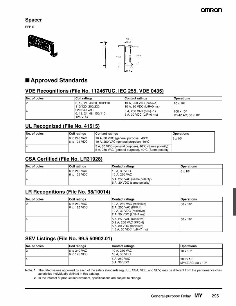
General-purpose Relay MY 295
SpacerPFP-S
■ Approved Standards
VDE Recognitions (File No. 112467UG, IEC 255, VDE 0435)
UL Recognized (File No. 41515)
CSA Certified (File No. LR31928)
LR Recognitions (File No. 98/10014)
SEV Listings (File No. 99.5 50902.01)
Note: 1. The rated values approved by each of the safety standards (eg., UL, CSA, VDE, and SEV) may be different from the performance char-acteristics individually defined in this catalog.
2. In the interest of product improvement, specifications are subject to change.
No. of poles Coil ratings Contact ratings Operations
2 6, 12, 24, 48/50, 100/110110/120, 200/220, 220/240 VAC6, 12, 24, 48, 100/110, 125 VDC
10 A, 250 VAC (cosφ=1)10 A, 30 VDC (L/R=0 ms)
10 x 103
4 5 A, 250 VAC (cosφ=1)5 A, 30 VDC (L/R=0 ms)
100 x 103
MY4Z AC; 50 x 103
No. of poles Coil ratings Contact ratings Operations
2 6 to 240 VAC6 to 125 VDC
10 A, 30 VDC (general purpose), 40°C10 A, 250 VAC (general purpose), 40°C
6 x 10³
4 5 A, 30 VDC (general purpose), 40°C (Same polarity)5 A, 250 VAC (general purpose), 40°C (Same polarity)
No. of poles Coil ratings Contact ratings Operations
2 6 to 240 VAC6 to 125 VDC
10 A, 30 VDC10 A, 250 VAC
6 x 10³
4 5 A, 250 VAC (same polarity)5 A, 30 VDC (same polarity)
No. of poles Coil ratings Contact ratings Operations
2 6 to 240 VAC6 to 125 VDC
10 A, 250 VAC (resistive)2 A, 250 VAC (PF0.4)10 A, 30 VDC (resistive)2 A, 30 VDC (L/R=7 ms)
50 x 103
4 5 A, 250 VAC (resistive)0.8 A, 250 VAC (PF0.4)5 A, 30 VDC (resistive)1.5 A, 30 VDC (L/R=7 ms)
50 x 103
No. of poles Coil ratings Contact ratings Operations
2 6 to 240 VAC6 to 125 VDC
10 A, 250 VAC10 A, 30 VDC
10 x 103
4 5 A, 250 VAC5 A, 30 VDC
100 x 103
MY4Z AC; 50 x 103
51612
44.3
16.5
34.8

296 General-purpose Relay MY
PYF-S Installation Notes
■ ToolsA flat-blade screwdriver should be used to mount the cables.
Applicable Screwdriver● Flat-blade, Parallel-tip, 2.5 mm diameter (3.0 mm max.)
Examples: FACOM AEF.2.5 × 75E (AEF. 3 × 75E)VESSEL No. 9900-(-)2.5 × 75 (No. 9900-(-)3 × 100)WAGO 210-119WIHA 260/2.5 × 40 (260/3 × 50)
*Chamfering the tip of the driver improves insertion when used as an exclusive tool.
■ Applicable Wires
Applicable Wire Sizes0.2 to 1.5 mm2, AWG24 to AWG16
Applicable Wire TypeSolid wires, stranded wires, flexible wires, or wires with ferules canbe used.
(See note 1.) < 2.2 ≤ Diameter D (mm) ≤ 3.2 (3.5: see note 2.)
Conductor diameter d (mm) or length of sides a and b (mm) ≤ 1.9
Note: 1. If the overall diameter of the wire is less than 2.2 mm, do notinsert the wire past the conductor. Refer to the following di-agrams.
2. If the overall diameter of the wire is over 3.2 mm, it will bedifficult to use double wiring.
● Flat-blade, Parallel-tip
● Flat-blade, Flared-tip2.5 dia. (3.0 mm max.)
Cannot be used.
Wires with Ferules

General-purpose Relay MY 297
Examples of Applicable Wires (Confirmed Using Catalog Information)
■ WiringUse wires of the applicable sizes specified above. The length of theexposed conductor should be 8 to 9 mm.
Use the following wiring procedure.
1. Insert the specified screwdriver into the release hole locatedbeside the wire connection hole where the wire is to be inserted.
2. Insert the exposed conductor into the wire connection hole.
3. Pull out the screwdriver.
Note: Use no more than 2 wires per terminal, 1 wire per hole.
Type of wire Conductor type See note 1, above. Recommended wire sizes See note 2, above.
Equipment wire 2491X Flexible 0.5, 0.75, 1.0 mm2 1.5 mm2
BS6004 Solid 0.5 mm2
Switchgear BS6231 Solid 1.0 mm2 1.5 mm2
Switchgear BS6231 Flexible 0.5, 0.75 mm2 1.0 mm2
Tri-rated control and switchgear Flexible 0.5, 0.75, 1.0, 1.5 mm2
Conduit Stranded 1.5 mm2
UL1007 Flexible 18AWG 16AWG
UL1015 Flexible 18AWG, 16AWG
UL1061 Flexible 18AWG
UL1430 Flexible 18AWG 16AWG
8 to 9 mm
Fig. 1 Exposed Conductor Length
Wire connection holes
Fig. 2 Wire Connection Holes and Release Holes
Release holes
Wire connection hole
Fig. 3 Section A-A of Fig. 2
Release hole
Screwdriver
Insert
Insert
Pull out

298 General-purpose Relay MY
■ Precautions
Precautions for Connection• Do not move the screwdriver up, down, or from side to side while it
is inserted in the hole. Doing so may cause damage to internalcomponents (e.g., deformation of the coil spring or cracks in thehousing) or cause deterioration of insulation.
• Do not insert the screwdriver at an angle. Doing so may break theside of socket and result in a short-circuit.
• Do not insert two or more wires in the hole. Wires may come in con-tact with the spring causing a temperature rise or be subject tosparks. (There are two wiring holes for each terminal.)
• Insert the screwdriver along the hole wall as shown below.
• If lubricating liquid, such as oil, is present on the tip of screwdriver,the screwdriver may fall out resulting in injury to the operator.
• Insert the screwdriver into the bottom of the hole. It may not be pos-sible to connect cables properly if the screwdriver is inserted incor-rectly.
General Precautions• Use the clip to prevent relays floating or falling out of the socket.• Do not use the product if it has been dropped on the ground. Drop-
ping the product may adversely affect performance.• Confirm that the socket is securely attached to the mounting track
before wiring. If the socket is mounted insecurely it may fall andinjure the operator.
• Ensure that the socket is not charged during wiring and mainte-nance. Not doing so may result in electric shock.
• Do not pour water or cleansing agents on the product. Doing somay result in electric shock.
• Do not use the socket in locations subject to solvents or alkalinechemicals.
• Do not use the socket in locations subject to ultraviolet light (e.g.,direct sunlight). Doing so may result in markings fading, rust, corro-sion, or resin deterioration.
• Do not dispose of the product in fire.
Removing from Mounting RailTo remove the socket from the mounting rail, insert the tip of screw-driver in the fixture rail, and move it in the direction shown below.
Screwdriver
Screwdriver
Fixture rail

General-purpose Relay MY
MEMO

General-purpose Relay MY
OMRON ON-LINEGlobal - http://www.omron.comUSA - http://www.components.omron.com
Cat. No. X301-E-1b Printed in USA
OMRON ELECTRONIC COMPONENTS LLC55 E. Commerce Drive, Suite BSchaumburg, IL 60173
847-882-228809/11 Specifications subject to change without notice
All sales are subject to Omron Electronic Components LLC standard terms and conditions of sale, which can be found at http://www.components.omron.com/components/web/webfiles.nsf/sales_terms.html
ALL DIMENSIONS SHOWN ARE IN MILLIMETERS.To convert millimeters into inches, multiply by 0.03937. To convert grams into ounces, multiply by 0.03527.


![The SOLUTIONS Relay Defects [General-purpose Relay Edition] · Title: The SOLUTIONS Relay Defects [General-purpose Relay Edition] Author: OMRON Keywords: Z384-E1-01 1216(1216) Created](https://static.fdocuments.in/doc/165x107/5f888cabfaba7c0dbe0691e4/the-solutions-relay-defects-general-purpose-relay-edition-title-the-solutions.jpg)