MX5,MX10,MX40,andMX80 3DUniversalEdgeRouter QuickStart · Title: MX5, MX10, MX40, and MX80 3D...
24
MX5, MX10, MX40, and MX80 3D Universal Edge Router Quick Start January 2015 Part Number: 530-062012 Revision 01 This document describes how to install the Juniper Networks ® MX5, MX10, MX40, and MX80 3D Universal Edge Router. Contents MX5, MX10, MX40, and MX80 Quick Start Description ...................... 3 Step 1: Prepare the Site for MX5, MX10, MX40, or MX80 Installation ........... 4 MX5, MX10, MX40, and MX80 Router Rack Requirements ................ 4 Tools Required to Prepare the MX5, MX10, MX40, and MX80 Router for Installation .................................................. 5 Move the Mounting Brackets for Center-Mounting the MX5, MX10, MX40, or MX80 Router, If Needed ..................................... 5 Step 2: Install the Router .............................................. 7 Tools Required to Install the MX5, MX10, MX40, or MX80 Router .......... 7 Install the MX5, MX10, MX40, or MX80 Chassis in the Rack ............... 7 Install the MX5, MX10, MX40, or MX80 Cable Management Bracket ....... 8 Step 3: Connect the Grounding Cable ................................... 10 Step 4: Connect External Devices and Cables ............................. 11 Connect the MX5, MX10, MX40, or MX80 Router to a Network for Out-of-Band Management ..................................... 11 Connect the MX5, MX10, MX40, or MX80 Router to a Management Console or Auxiliary Device ............................................ 11 Connect MIC Cables to the MX5, MX10, MX40, or MX80 Router ........... 11 Step 5: Connect Power Cables ......................................... 13 Connect Power to an AC Router .................................... 13 Connect Power to a DC Router ..................................... 14 Step 6: Perform Initial Software Configuration ............................ 16 Enter Configuration Mode ......................................... 16 Configure User Accounts and Passwords ............................. 16 Configure System Attributes ....................................... 17 1 Copyright © 2015, Juniper Networks, Inc.
Transcript of MX5,MX10,MX40,andMX80 3DUniversalEdgeRouter QuickStart · Title: MX5, MX10, MX40, and MX80 3D...

MX5, MX10, MX40, and MX80
3D Universal Edge Router
Quick Start
January 2015Part Number: 530-062012Revision 01
This document describes how to install the Juniper Networks®MX5, MX10, MX40, and
MX80 3D Universal Edge Router.
Contents MX5, MX10, MX40, and MX80 Quick Start Description . . . . . . . . . . . . . . . . . . . . . . 3
Step 1: Prepare the Site for MX5, MX10, MX40, or MX80 Installation . . . . . . . . . . . 4
MX5, MX10, MX40, and MX80 Router Rack Requirements . . . . . . . . . . . . . . . . 4
Tools Required to Prepare the MX5, MX10, MX40, and MX80 Router for
Installation . . . . . . . . . . . . . . . . . . . . . . . . . . . . . . . . . . . . . . . . . . . . . . . . . . 5
Move the Mounting Brackets for Center-Mounting the MX5, MX10, MX40,
or MX80 Router, If Needed . . . . . . . . . . . . . . . . . . . . . . . . . . . . . . . . . . . . . 5
Step 2: Install the Router . . . . . . . . . . . . . . . . . . . . . . . . . . . . . . . . . . . . . . . . . . . . . . 7
Tools Required to Install the MX5, MX10, MX40, or MX80 Router . . . . . . . . . . 7
Install the MX5, MX10, MX40, or MX80 Chassis in the Rack . . . . . . . . . . . . . . . 7
Install the MX5, MX10, MX40, or MX80 Cable Management Bracket . . . . . . . 8
Step 3: Connect the Grounding Cable . . . . . . . . . . . . . . . . . . . . . . . . . . . . . . . . . . . 10
Step 4: Connect External Devices and Cables . . . . . . . . . . . . . . . . . . . . . . . . . . . . . 11
Connect the MX5, MX10, MX40, or MX80 Router to a Network for
Out-of-Band Management . . . . . . . . . . . . . . . . . . . . . . . . . . . . . . . . . . . . . 11
Connect theMX5,MX10,MX40, orMX80Router to aManagement Console
or Auxiliary Device . . . . . . . . . . . . . . . . . . . . . . . . . . . . . . . . . . . . . . . . . . . . 11
Connect MIC Cables to the MX5, MX10, MX40, or MX80 Router . . . . . . . . . . . 11
Step 5: Connect Power Cables . . . . . . . . . . . . . . . . . . . . . . . . . . . . . . . . . . . . . . . . . 13
Connect Power to an AC Router . . . . . . . . . . . . . . . . . . . . . . . . . . . . . . . . . . . . 13
Connect Power to a DC Router . . . . . . . . . . . . . . . . . . . . . . . . . . . . . . . . . . . . . 14
Step 6: Perform Initial Software Configuration . . . . . . . . . . . . . . . . . . . . . . . . . . . . 16
Enter Configuration Mode . . . . . . . . . . . . . . . . . . . . . . . . . . . . . . . . . . . . . . . . . 16
Configure User Accounts and Passwords . . . . . . . . . . . . . . . . . . . . . . . . . . . . . 16
Configure System Attributes . . . . . . . . . . . . . . . . . . . . . . . . . . . . . . . . . . . . . . . 17
1Copyright © 2015, Juniper Networks, Inc.

Commit the Configuration . . . . . . . . . . . . . . . . . . . . . . . . . . . . . . . . . . . . . . . . . 17
Safety Warnings . . . . . . . . . . . . . . . . . . . . . . . . . . . . . . . . . . . . . . . . . . . . . . . . . . . . 19
Compliance Statements for NEBS . . . . . . . . . . . . . . . . . . . . . . . . . . . . . . . . . . . . . 20
Compliance Statements for EMC Requirements . . . . . . . . . . . . . . . . . . . . . . . . . . . 21
Canada . . . . . . . . . . . . . . . . . . . . . . . . . . . . . . . . . . . . . . . . . . . . . . . . . . . . . . . . 21
European Community . . . . . . . . . . . . . . . . . . . . . . . . . . . . . . . . . . . . . . . . . . . . 21
Israel . . . . . . . . . . . . . . . . . . . . . . . . . . . . . . . . . . . . . . . . . . . . . . . . . . . . . . . . . . 21
Japan . . . . . . . . . . . . . . . . . . . . . . . . . . . . . . . . . . . . . . . . . . . . . . . . . . . . . . . . . 21
United States . . . . . . . . . . . . . . . . . . . . . . . . . . . . . . . . . . . . . . . . . . . . . . . . . . . 22
Junos OS Documentation and Release Notes . . . . . . . . . . . . . . . . . . . . . . . . . . . . . 23
Requesting Technical Support . . . . . . . . . . . . . . . . . . . . . . . . . . . . . . . . . . . . . . . . . 23
Self-Help Online Tools and Resources . . . . . . . . . . . . . . . . . . . . . . . . . . . . . . . 23
Opening a Case with JTAC . . . . . . . . . . . . . . . . . . . . . . . . . . . . . . . . . . . . . . . . 24
Revision History . . . . . . . . . . . . . . . . . . . . . . . . . . . . . . . . . . . . . . . . . . . . . . . . . . . . 24
Copyright © 2015, Juniper Networks, Inc.2
MX5, MX10, MX40, and MX80 3D Universal Edge Router Quick Start

MX5, MX10, MX40, andMX80Quick Start Description
ThisQuick Start contains information you need to install and configure the router quickly.
For complete installation instructions, see theMX5,MX10, MX40, andMX80 3DUniversal
Edge Router Hardware Guide at http://www.juniper.net/techpubs/.
WARNING: ThisQuickStart containsasummaryofsafetywarnings in “SafetyWarnings”onpage 19. Foracomplete list ofwarnings for this router, includingtranslations, see theMX5, MX10, MX40, and MX80 3D Universal Edge RouterHardware Guide at http://www.juniper.net/techpubs/.
The MX5, MX10, MX40, and MX80 routers are available as amodular chassis with two
dedicated slots for Modular Interface Cards (MICs) that provide scalable configuration
options. Software licenses allow you to upgrade from one router to another without a
hardware upgrade. The ports are restricted based on the router’s associated license as
follows:
• MX5 router: allows usage of the MIC slot labeled 1/MIC 0which comes pre-populated
with the Gigabit Ethernet MIC with SFP.
• MX10 router: allows usage of theMIC slot labeled 1/MIC0which comes pre-populated
with the Gigabit Ethernet MIC with SFP and the second MIC slot labeled 1/MIC 1.
• MX40 router: allowsusageof bothMIC slots andports0and 1of thebuilt-in 10-Gigabit
Ethernet MIC (labeled 0/MIC 0).
• MX80 router: allowsusageof bothMIC slots andall four ports of thebuilt-in 10-Gigabit
Ethernet MIC (labeled 0/MIC 0).
A fixed version of the MX80 router (model number: MX80-48T) has 48 fixed
10/100/1000Base-T RJ45 ports in place of the MIC slots.
For a list of MICs supported on the MX5, MX10, MX40, andmodular MX80 routers, see
MICs Supported by MX Series Routers in theMX Series Interface Module Reference.
3Copyright © 2015, Juniper Networks, Inc.
MX5, MX10, MX40, and MX80 Quick Start Description

Step 1: Prepare the Site for MX5, MX10, MX40, or MX80 Installation
• MX5, MX10, MX40, and MX80 Router Rack Requirements on page 4
• Tools Required to Prepare the MX5, MX10, MX40, and MX80 Router for
Installation on page 5
• Move the Mounting Brackets for Center-Mounting the MX5, MX10, MX40, or MX80
Router, If Needed on page 5
MX5, MX10, MX40, andMX80 Router Rack Requirements
• You can install the router in a four-post rack or cabinet or an open-frame rack.
• The rack rails must be spaced widely enough to accommodate the router chassis's
external dimensions: 3.5 in. (8.9 cm)high, 21.75 in. (55.2 cm)deep, and 17.4 in. (44.2 cm)
wide. The outer edges of themounting brackets extend the width to 19.2 in. (48.7 cm).
• The rack must be strong enough to support the weight of the fully configured router,
up to 30 lb (13.6 kg).
• For the cooling system to function properly, the airflow around the chassis must be
unrestricted. Allow at least 6 in. (15.2 cm) of clearance between side-cooled routers.
Allow 2.8 in. (7 cm) between the side of the chassis and any non-heat-producing
surface such as a wall.
• For service personnel to remove and install hardware components, there must be
adequate space at the front and back of the router. Allow at least 30 in. (76.2 cm) in
front of the router and 24 in. (61 cm) behind the router.
• The rack or cabinet must have an adequate supply of cooling air.
• Ensure that the cabinet allows the chassis hot exhaust air to exit from the cabinet
without recirculating into the router.
• The router must be installed into a rack that is secured to the building structure.
• Mount the router at the bottom of the rack if it is the only unit in the rack.
• Whenmounting the router in a partially filled rack, load the rack from the bottom to
the top with the heaviest component at the bottom of the rack.
Copyright © 2015, Juniper Networks, Inc.4
MX5, MX10, MX40, and MX80 3D Universal Edge Router Quick Start

Figure 1: MX5, MX10, MX40, andMX80 Rack Clearance and RouterDimensions
Rear of chassisFront of chassis17.5"
(44.5 cm)
20.2"(51.3 cm)
g005
017
Front-mounting flange
19.2"(48.7 cm)
24" (61 cm)clearance required
30" (76.2 cm)clearance recommended for
maintenance
Cablemanagementbracket
23.46"(59.6cm)
Tools Required to Prepare theMX5, MX10, MX40, andMX80 Router for Installation
• Blank panels to cover any slots not occupied by a component
• Mounting brackets, supplied with the router
• Eight screws for securing themountingbrackets to thechassis, suppliedwith the router
• Phillips (+) screwdriver, number 2
Move theMounting Brackets for Center-Mounting theMX5, MX10, MX40, or MX80 Router, IfNeeded
Two removable mounting brackets are attached to the mounting holes closest to the
front of the chassis (see Figure 2 on page 6). You canmove the pair of brackets to
another position on the side of the chassis for center-mounting the router.
To move themounting brackets from the front of the chassis toward the center of the
chassis (see Figure 3 on page 6):
1. Remove the four screws at the top and bottom of the bracket.
2. Pull the bracket away from the chassis.
3. Align the bracket with the two sets of mounting holes located toward the center of
the chassis.
4. Insert the four screws at the top and bottomof the bracket and tighten each partially.
5. Tighten the four screws completely.
6. Repeat the procedure for the other bracket.
5Copyright © 2015, Juniper Networks, Inc.
Tools Required to Prepare the MX5, MX10, MX40, and MX80 Router for Installation

Figure 2: Front-Mount the Brackets on theMX5, MX10, MX40, or MX80Router
g005
018
Figure 3: Center-Mount the Brackets on theMX5, MX10, MX40, or MX80Router
g005
019
Copyright © 2015, Juniper Networks, Inc.6
MX5, MX10, MX40, and MX80 3D Universal Edge Router Quick Start

Step 2: Install the Router
• Tools Required to Install the MX5, MX10, MX40, or MX80 Router on page 7
• Install the MX5, MX10, MX40, or MX80 Chassis in the Rack on page 7
• Install the MX5, MX10, MX40, or MX80 Cable Management Bracket on page 8
Tools Required to Install theMX5, MX10, MX40, or MX80 Router
To install the router in a rack, you need the following tools:
• Phillips (+) screwdriver, number 2
• ESD grounding wrist strap
• Four mounting screws, supplied with the chassis
• Cable management bracket, supplied with the router
• Two screws for securing the cable management bracket, supplied with the router
Install theMX5, MX10, MX40, or MX80 Chassis in the Rack
Lifting the chassis andmounting it in a rack requires two people. The chassis weighs
approximately 30 lb (13.6 kg).
1. Ensure that the rack is in its permanent location and is secured to the building. Ensure
that the installation site allowsadequate clearance for bothairflowandmaintenance.
2. Position the router in front of the rack or cabinet.
3. With one person on each side, hold onto the bottom of the chassis and carefully lift
it so that the mounting brackets contact the rack rails.
4. Align the mounting brackets with the holes in the rack rails.
5. Install a mounting screw into each of the openmounting holes aligned with the rack,
starting from the bottom.
6. Visually inspect the alignment of the router. If the router is installed properly in the
rack, all the mounting screws on one side of the rack should be aligned with the
mounting screws on the opposite side and the router should be level.
7Copyright © 2015, Juniper Networks, Inc.
Step 2: Install the Router

Figure 4: Install the Front-Mounted Router in the Rack
Mounting rack
Mounting bracket
g005
020
Figure 5: Install the Center-Mounted Router in the Rack
Mounting rack
Mounting bracket
g005
044
Install theMX5, MX10, MX40, or MX80 Cable Management Bracket
1. Position the cable management bracket on the left side of the front of the chassis.
2. Tighten the screws at the bottom and top of the bracket.
Copyright © 2015, Juniper Networks, Inc.8
MX5, MX10, MX40, and MX80 3D Universal Edge Router Quick Start

Figure 6: Install the Cable Management Bracket
g005
036
9Copyright © 2015, Juniper Networks, Inc.
Install the MX5, MX10, MX40, or MX80 Cable Management Bracket

Step 3: Connect the Grounding Cable
Youground the routerbyconnectingagroundingcable toearthgroundand thenattaching
it to the chassis grounding points using two SAE 10-32 screws. Youmust provide the
grounding cables (the cable lugs are suppliedwith the router). To ground theMX5,MX10,
MX40, or MX80 router:
1. Verify that a licensed electrician has attached the cable lug provided with the router
to the grounding cable.
2. Attachanelectrostaticdischarge (ESD)groundingstrap toyourbarewrist, andconnect
the strap to an approved site ESD grounding point. See the instructions for your site.
3. Ensure that all grounding surfaces are clean and brought to a bright finish before
grounding connections are made.
4. Connect the grounding cable to a proper earth ground.
5. Detach the ESD grounding strap from the site ESD grounding point.
6. Attach an ESD grounding strap to your bare wrist and connect the strap to one of the
ESD points on the chassis.
7. Place the grounding cable lug over the grounding points on the upper rear of the
chassis (see Figure 7 on page 10).
8. Secure the grounding cable lug with the screws. The holes are sized for SAE 10-32
screws.
9. Dress the grounding cable and verify that it does not touch or block access to router
components, and that it does not drape where people could trip on it.
Figure 7: Grounding Points on theMX5, MX10, MX40, or MX80 Router
g005
009CLOCK SYNC
Protectiveearthing terminal(grounding points)
Copyright © 2015, Juniper Networks, Inc.10
MX5, MX10, MX40, and MX80 3D Universal Edge Router Quick Start

Step 4: Connect External Devices and Cables
Figure 8: Routing Engine Ethernet Cable Connector
Figure 9: Front Panel Ports
g005
046
ONLINE/OFFLINE
Auxiliaryport
USBport 10-Gigabit Ethernet MIC
Consoleport
Ethernetport
Clockports
RoutingEngineLED
AlarmLEDs
SystemstatusLED
Resetbutton
ONLINE/OFFLINEbutton
• Connect the MX5, MX10, MX40, or MX80 Router to a Network for Out-of-Band
Management on page 11
• Connect theMX5,MX10,MX40, orMX80Router to aManagementConsole orAuxiliary
Device on page 11
• Connect MIC Cables to the MX5, MX10, MX40, or MX80 Router on page 11
Connect theMX5, MX10, MX40, or MX80 Router to a Network for Out-of-BandManagement
1. Turn off the power to the management device.
2. Plug one end of the Ethernet cable (Figure 8 on page 11 shows the connector) into
the ETHERNET port on the Routing Engine. Figure 9 on page 11 shows the port.
3. Plug the other end of the cable into the network device.
Connect theMX5,MX10,MX40, orMX80Router to aManagement Console or Auxiliary Device
1. Turn off the power to the console or auxiliary device.
2. Plug the RJ-45 end of the serial cable (Figure 8 on page 11 shows the connector) into
theAUXport orCONSOLEport on the front panel. Figure 9 on page 11 shows the ports.
3. Plug the female DB-9 end into the device's serial port.
Connect MIC Cables to theMX5, MX10, MX40, or MX80 Router
1. Have ready a length of the type of cable used by the component. For MIC cable
specifications, see theMX Series Interface Module Reference.
2. Remove the rubber safety plug from the cable connector port.
11Copyright © 2015, Juniper Networks, Inc.
Step 4: Connect External Devices and Cables

WARNING: Do not look directly into a fiber-optic transceiver or into theends of fiber-optic cables. Fiber-optic transceivers and fiber-optic cableconnected to a transceiver emit laser light that can damage your eyes.
CAUTION: Do not leave a fiber-optic transceiver uncovered except wheninserting or removing cable. The safety cap keeps the port clean andprevents accidental exposure to laser light.
3. Insert the cable connector into the cable connector port on the faceplate.
NOTE: TheXFPcagesandopticsonthecomponentsare industrystandardparts that have limited tactile feedback for insertion of optics and fiber.You need to insert the optics and fiber firmly until the latch is securely inplace.
4. Arrange the cable to prevent it from dislodging or developing stress points. Secure
the cable so that it is not supporting its own weight as it hangs to the floor. Place
excess cable out of the way in a neatly coiled loop.
CAUTION: Avoid bending fiber-optic cable beyond its minimum bendradius.Anarc smaller thana few inches indiameter candamage thecableand cause problems that are difficult to diagnose.
CAUTION: Do not let fiber-optic cable hang free from the connector. Donot allow fastened loops of cable to dangle, which stresses the cable atthe fastening point.
Copyright © 2015, Juniper Networks, Inc.12
MX5, MX10, MX40, and MX80 3D Universal Edge Router Quick Start
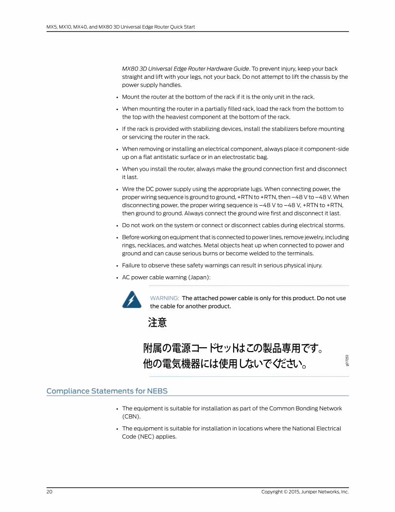
Step 5: Connect Power Cables
Dependingonyour configuration, your router useseitherACorDCpower supplies. Perform
the appropriate procedures for each power supply in your router.
WARNING: Youmust ground the router before connecting either the ACpower cord or the DC power cables.
• Connect Power to an AC Router on page 13
• Connect Power to a DC Router on page 14
Connect Power to an AC Router
1. Locate power cords that have a plug appropriate for your geographical location. For
more information, see theMX5, MX10, MX40, and MX80 3D Universal Edge Router
Hardware Guide.
2. Attach an ESD grounding strap to your bare wrist and connect the strap to one of the
ESD points on the chassis.
3. Move theAC input switchnext to theappliance inlet on thepower supply to theoff (O)
position.
4. Connect the power cord to the power supply.
5. Insert the power cord plug into an external AC power source receptacle.
NOTE: Each power supply must be connected to a dedicated AC powerfeed and a dedicated customer site circuit breaker. We recommend thatyou use a dedicated customer site circuit breaker rated for either15 A (110 VAC)minimum or 10 A (220 VAC)minimum, or as required bylocal code.
6. Dress the power cord appropriately. Verify that the power cord does not block the air
exhaust and access to router components, or drape where people could trip on it.
7. Repeat Step 1 through Step 6 for the remaining power supply.
8. Switch the AC switch on each power supply to the on position (I) and observe the
status LEDoneachpower supply faceplate. If anACpower supply is correctly installed
and functioning normally, the status LED lights green steadily.
If the status LED indicates that the power supply is not functioning normally, repeat
the installation and cabling procedures.
13Copyright © 2015, Juniper Networks, Inc.
Step 5: Connect Power Cables

Connect Power to a DC Router
Table 1: MX5, MX10, MX40, andMX80DC Power System Input Voltage
SpecificationItem
Operating range: –40 to –72 VDCDC input voltage
1. Switchoff thededicated customer site circuit breakers. Ensure that the voltageacross
the DC power source cable leads is 0 V and that there is no chance that the cable
leads might become active during installation.
2. Switch the DC circuit breaker on the power supply faceplate to the off (O) position.
3. Remove the clear plastic cover protecting the terminal on the faceplate.
4. Verify that the DC power cables are correctly labeled before making connections to
thepower supply. In a typical powerdistribution schemewhere the return is connected
to chassis groundat thebattery plant, youcanuseamultimeter to verify the resistance
of the –48V and RTN DC cables to chassis ground:
• The cable with very large resistance (indicating an open circuit) to chassis ground
is –48V.
• The cable with very low resistance (indicating a closed circuit) to chassis ground is
RTN.
5. Remove the screws from the terminals.
6. Secure eachpower cable lug to the terminalwith the screw (see Figure 10onpage 15).
Apply between 5 lb-in. (0.6 Nm) and 6 lb-in. (0.7 Nm) of torque to screw. Do not
overtighten the nut. (Use a number 2 Phillips screwdriver.)
a. Secure the positive (+) DC source power cable lug to the RTN (return) terminal.
b. Secure the negative (–) DC source power cable lug to the –48V (input) terminal.
CAUTION: Ensure thateachpowercable lugseats flushagainst thesurfaceof the terminal block as you are tightening the screws. Ensure that eachscrew is properly threaded into the terminal. Applying installation torqueto the screwwhen improperly threadedmay result in damage to theterminal.
CAUTION: Themaximum torque rating of the terminal screws on the DCpower supply is 6 lb-in. (0.7 Nm). The terminal screwsmay be damagedif excessive torque isapplied.Useonlya torque-controlleddriver to tightenscrews on the DC power supply terminals. Use an appropriately-sizeddriver, with amaximum torque capacity of 6 lb-in. or less. Ensure that thedriver is undamaged and properly calibrated and that you have been
Copyright © 2015, Juniper Networks, Inc.14
MX5, MX10, MX40, and MX80 3D Universal Edge Router Quick Start

trained in its use. Youmaywish to use a driver that is designed to preventovertorque when the preset torque level is achieved.
7. Replace the clear plastic cover over the terminals on the faceplate.
8. Repeat Step 2 through Step 7 for the remaining power supplies.
9. Attachanelectrostaticdischarge (ESD)groundingstrap toyourbarewrist, andconnect
the strap to an approved site ESD grounding point. See the instructions for your site.
10. Connect each DC power cable to the appropriate external DC power source.
NOTE: For information about connecting to external DC power sources,see the instructions for your site.
11. Switch on the external circuit breakers to provide voltage to the DC power source
cable leads.
12. Switch on the circuit breakers on each power supply to the on position (|). Observe
the status LED on each power supply faceplate. If a DC power supply is correctly
installed and functioning normally, the status LED lights green steadily.
If the status LED indicates that the power supply is not functioning normally, repeat
the installation and cabling procedures.
Figure 10: Connecting DC Power to the Router
g005
006
15Copyright © 2015, Juniper Networks, Inc.
Connect Power to a DC Router

Step 6: Perform Initial Software Configuration
This procedure connects the router to the network but does not enable it to forward
traffic. For complete information about configuring the router to forward traffic, including
examples, see the Junos OS configuration guides.
To configure the software:
• Enter Configuration Mode on page 16
• Configure User Accounts and Passwords on page 16
• Configure System Attributes on page 17
• Commit the Configuration on page 17
Enter ConfigurationMode
1. Verify that the router is powered on.
2. Log in as the “root” user. There is no password.
3. Start the CLI.
root# cliroot@>
4. Enter configuration mode.
cli> configure[edit]root@#
Configure User Accounts and Passwords
For information about using an encrypted password or an SSH public key string (DSA or
RSA), see authentication.
1. Add a password to the root administration user account. Enter a clear-text password.
[edit]root# set system root-authentication plain-text-passwordNew password: passwordRetype new password: password
2. Create amanagement console user account.
[edit]root# set system login user user-name authentication plain-text-passwordNew Password: passwordRetype new password: password
3. Set the user account class to super-user.
[edit]root@# set system login user user-name class super-user
Copyright © 2015, Juniper Networks, Inc.16
MX5, MX10, MX40, and MX80 3D Universal Edge Router Quick Start

Configure SystemAttributes
1. Configure the name of the router. If the name includes spaces, enclose the name in
quotation marks (“ ”).
[edit]root@# set system host-name host-name
2. Configure the router’s domain name.
[edit]root@# set system domain-name domain-name
3. Configure the IP address and prefix length for the router’s Ethernet interface.
[edit]root@# set interfaces fxp0 unit 0 family inet address address/prefix-length
4. Configure the IP address of a backup router, which is used only while the routing
protocol is not running.
[edit]root@# set system backup-router address
5. Configure the IP address of a DNS server.
[edit]root@# set system name-server address
6. (Optional) Configure the static routes to remote subnets with access to the
management port. Access to the management port is limited to the local subnet. To
access the management port from a remote subnet, you need to add a static route
to that subnet within the routing table. For more information about static routes, see
the Junos OS Administration Library for Routing Devices.
[edit]root@# set routing-options static route remote-subnet next-hop destination-IP retainno-readvertise
7. Configure the telnet service at the [edit system services] hierarchy level.
[edit]root@# set system services telnet
Commit the Configuration
1. (Optional) Display the configuration to verify that it is correct.
[edit]root@# showsystem {host-name host-name;domain-name domain-name;backup-router address;root-authentication {authentication-method (password | public-key);
}name-server {address;
17Copyright © 2015, Juniper Networks, Inc.
Configure System Attributes

}}interfaces {fxp0 {unit 0 {family inet {address address/prefix-length;
}}
}}
2. Commit the configuration to activate it on the router.
[edit]root@# commit
3. (Optional) Configure additional properties by adding the necessary configuration
statements. Then commit the changes to activate them on the router.
[edit]root@host# commit
4. When you have finished configuring the router, exit configuration mode.
[edit]root@host# exitroot@host>
Copyright © 2015, Juniper Networks, Inc.18
MX5, MX10, MX40, and MX80 3D Universal Edge Router Quick Start

SafetyWarnings
WARNING: See installation instructions before connecting the router. Thisis a summary of safety warnings. For a complete list of warnings for thisrouter, including translations, see theMX5, MX10, MX40, and MX80 3DUniversal Edge Router Hardware Guide at http://www.juniper.net/techpubs/.
WARNING: The intrabuilding port(s) of the router is suitable for connectionto intrabuilding or unexposedwiring or cabling only. The intrabuilding port(s)of the routerMUSTNOTbemetallically connected to interfaces that connectto theOSPor itswiring. These interfacesaredesigned for useas intrabuildinginterfaces only (Type 2 or Type 4 ports as described in GR-1089-CORE, Issue4)andrequire isolation fromtheexposedOSPcabling.Theadditionofprimaryprotectors is not sufficientprotection toconnect these interfacesmetallicallyto OSPwiring.
CAUTION: Before removing or installing components of a router, attach anESD strap to an ESD point, and place the other end of the strap around yourbare wrist. Failure to use an ESD strap could result in damage to the router.
CAUTION: Use an external surge protective device (SPD) at the AC input ofthe router.
• Only trained and qualified personnel should install or replace the router.
• Perform only the procedures described in this quick start or theMX5, MX10, MX40, and
MX80 3D Universal Edge Router Hardware Guide. Other services should be performed
by authorized service personnel only.
• Read the installation instructions before you connect the router to a power source.
• Before installing the router, read the guidelines for site preparation in theMX5, MX10,
MX40, and MX80 3D Universal Edge Router Hardware Guide to make sure that the site
meets power, environmental, and clearance requirements for the router.
• For the cooling system to function properly, the airflow around the chassis must be
unrestricted. Allow at least 6 in. (15.2 cm) of clearance between side-cooled routers.
Allow 2.8 in. (7 cm) between the side of the chassis and any non-heat-producing
surface such as a wall.
• When installing the router, do not use a ramp inclinedmore than 10 degrees.
• Manually installing the router requires two people for an empty chassis and three
people for a fully configured router to lift the chassis. Before lifting the chassis with
only two people, remove the components as described in theMX5, MX10, MX40, and
19Copyright © 2015, Juniper Networks, Inc.
SafetyWarnings
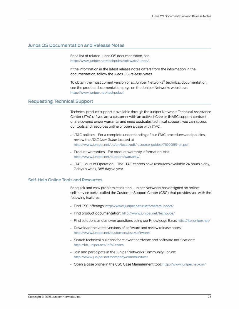
MX80 3D Universal Edge Router Hardware Guide. To prevent injury, keep your back
straight and lift with your legs, not your back. Do not attempt to lift the chassis by the
power supply handles.
• Mount the router at the bottom of the rack if it is the only unit in the rack.
• Whenmounting the router in a partially filled rack, load the rack from the bottom to
the top with the heaviest component at the bottom of the rack.
• If the rack is provided with stabilizing devices, install the stabilizers before mounting
or servicing the router in the rack.
• When removing or installing an electrical component, always place it component-side
up on a flat antistatic surface or in an electrostatic bag.
• When you install the router, always make the ground connection first and disconnect
it last.
• Wire the DC power supply using the appropriate lugs. When connecting power, the
properwiring sequence is ground toground,+RTNto+RTN, then–48V to–48V.When
disconnecting power, the proper wiring sequence is –48 V to –48 V, +RTN to +RTN,
then ground to ground. Always connect the ground wire first and disconnect it last.
• Do not work on the system or connect or disconnect cables during electrical storms.
• Beforeworkingonequipment that is connected topower lines, remove jewelry, including
rings, necklaces, and watches. Metal objects heat up when connected to power and
ground and can cause serious burns or becomewelded to the terminals.
• Failure to observe these safety warnings can result in serious physical injury.
• AC power cable warning (Japan):
WARNING: The attached power cable is only for this product. Do not usethe cable for another product.
Compliance Statements for NEBS
• The equipment is suitable for installation as part of the Common Bonding Network
(CBN).
• The equipment is suitable for installation in locations where the National Electrical
Code (NEC) applies.
Copyright © 2015, Juniper Networks, Inc.20
MX5, MX10, MX40, and MX80 3D Universal Edge Router Quick Start

• The battery return connection is to be treated as an isolated DC return (i.e. DC-I), as
defined in GR-1089-CORE.
• For Juniper systemswith ACpower supplies, an external surge protective device (SPD)
must be used at the AC power source.
Compliance Statements for EMC Requirements
• Canada on page 21
• European Community on page 21
• Israel on page 21
• Japan on page 21
• United States on page 22
Canada
This Class A digital apparatus complies with Canadian ICES-003.
Cet appareil numérique de la classe A est conforme à la norme NMB-003 du Canada.
European Community
This is a Class A product. In a domestic environment this product may cause radio
interference in which case the user may be required to take adequate measures.
Israel
Translation from Hebrew—Warning: This product is Class A. In residential environments,
theproductmaycause radio interference, and in suchasituation, theusermaybe required
to take adequate measures.
Japan
Translation from Japanese—This is a Class A product. In a domestic environment this
product may cause radio interference in which case the user may be required to take
adequate measures. VCCI-A
21Copyright © 2015, Juniper Networks, Inc.
Compliance Statements for EMC Requirements

United States
Thehardware equipment has been tested and found to complywith the limits for aClass
Adigital device, pursuant toPart 15 of the FCCRules. These limits are designed toprovide
reasonable protection against harmful interference when the equipment is operated in
a commercial environment. This equipment generates, uses, and can radiate radio
frequencyenergyand, if not installedandused inaccordancewith the instructionmanual,
may cause harmful interference to radio communications. Operation of this equipment
in a residential area is likely to cause harmful interference in which case the user will be
required to correct the interference at his own expense.
Copyright © 2015, Juniper Networks, Inc.22
MX5, MX10, MX40, and MX80 3D Universal Edge Router Quick Start
Junos OS Documentation and Release Notes
For a list of related Junos OS documentation, see
http://www.juniper.net/techpubs/software/junos/.
If the information in the latest release notes differs from the information in the
documentation, follow the Junos OS Release Notes.
To obtain the most current version of all Juniper Networks®technical documentation,
see the product documentation page on the Juniper Networks website at
http://www.juniper.net/techpubs/.
Requesting Technical Support
Technical product support is available through the JuniperNetworksTechnicalAssistance
Center (JTAC). If you are a customer with an active J-Care or JNASC support contract,
or are covered under warranty, and need postsales technical support, you can access
our tools and resources online or open a case with JTAC.
• JTAC policies—For a complete understanding of our JTAC procedures and policies,
review the JTAC User Guide located at
http://www.juniper.net/us/en/local/pdf/resource-guides/7100059-en.pdf.
• Product warranties—For product warranty information, visit
http://www.juniper.net/support/warranty/.
• JTAC Hours of Operation —The JTAC centers have resources available 24 hours a day,
7 days a week, 365 days a year.
Self-Help Online Tools and Resources
For quick and easy problem resolution, Juniper Networks has designed an online
self-service portal called the Customer Support Center (CSC) that provides youwith the
following features:
• Find CSC offerings: http://www.juniper.net/customers/support/
• Find product documentation: http://www.juniper.net/techpubs/
• Find solutions and answer questions using our Knowledge Base: http://kb.juniper.net/
• Download the latest versions of software and review release notes:
http://www.juniper.net/customers/csc/software/
• Search technical bulletins for relevant hardware and software notifications:
http://kb.juniper.net/InfoCenter/
• Join and participate in the Juniper Networks Community Forum:
http://www.juniper.net/company/communities/
• Open a case online in the CSC Case Management tool: http://www.juniper.net/cm/
23Copyright © 2015, Juniper Networks, Inc.
Junos OS Documentation and Release Notes

Toverify serviceentitlementbyproduct serial number, useourSerialNumberEntitlement
(SNE) Tool: https://tools.juniper.net/SerialNumberEntitlementSearch/
Opening a Casewith JTAC
You can open a case with JTAC on theWeb or by telephone.
• Use the Case Management tool in the CSC at http://www.juniper.net/cm/.
• Call 1-888-314-JTAC (1-888-314-5822 toll-free in the USA, Canada, and Mexico).
For international or direct-dial options in countries without toll-free numbers, visit us at
http://www.juniper.net/support/requesting-support.html
Revision History
January 2015—530-062012. Revision 1. Minor updates.
December 2011—530-038841. Revision 1. Added MX5, MX10, and MX40 routers.
August 2010—530-036363. Revision 1. Minor updates.
May 2010—530-034538. Revision 1. Initial release.
Copyright © 2015, Juniper Networks, Inc. All rights reserved.
Juniper Networks, Junos, Steel-Belted Radius, NetScreen, and ScreenOS are registered trademarks of Juniper Networks, Inc. in the UnitedStates and other countries. The Juniper Networks Logo, the Junos logo, and JunosE are trademarks of Juniper Networks, Inc. All othertrademarks, service marks, registered trademarks, or registered service marks are the property of their respective owners.
Juniper Networks assumes no responsibility for any inaccuracies in this document. Juniper Networks reserves the right to change, modify,transfer, or otherwise revise this publication without notice.
Copyright © 2015, Juniper Networks, Inc.24
MX5, MX10, MX40, and MX80 3D Universal Edge Router Quick Start