MX Technology Addressable Devices · Features MX Technology addressable smoke sensor, heat sensor...
8
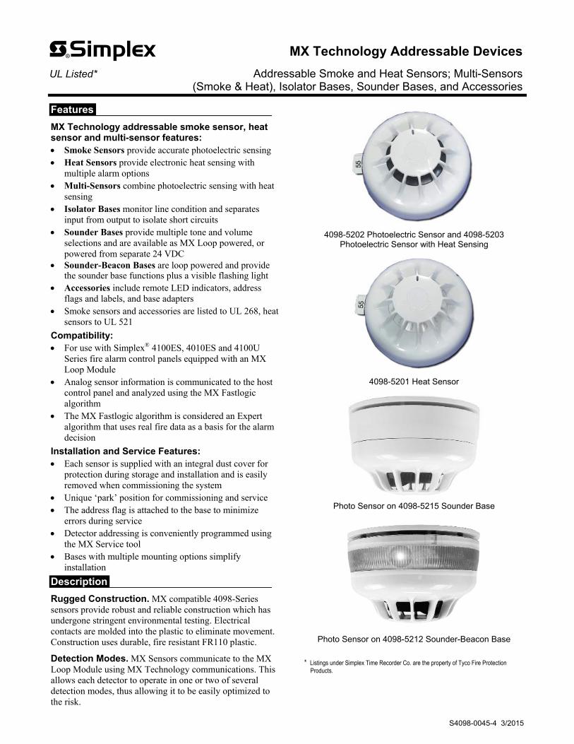
Features MX Technology addressable smoke sensor, heat sensor and multi-sensor features: Smoke Sensors provide accurate photoelectric sensing Heat Sensors provide electronic heat sensing with multiple alarm options Multi-Sensors combine photoelectric sensing with heat sensing Isolator Bases monitor line condition and separates input from output to isolate short circuits Sounder Bases provide multiple tone and volume selections and are available as MX Loop powered, or powered from separate 24 VDC Sounder-Beacon Bases are loop powered and provide the sounder base functions plus a visible flashing light Accessories include remote LED indicators, address flags and labels, and base adapters Smoke sensors and accessories are listed to UL 268, heat sensors to UL 521 Compatibility: For use with Simplex ® 4100ES, 4010ES and 4100U Series fire alarm control panels equipped with an MX Loop Module Analog sensor information is communicated to the host control panel and analyzed using the MX Fastlogic algorithm The MX Fastlogic algorithm is considered an Expert algorithm that uses real fire data as a basis for the alarm decision Installation and Service Features: Each sensor is supplied with an integral dust cover for protection during storage and installation and is easily removed when commissioning the system Unique ‘park’ position for commissioning and service The address flag is attached to the base to minimize errors during service Detector addressing is conveniently programmed using the MX Service tool Bases with multiple mounting options simplify installation Description Rugged Construction. MX compatible 4098-Series sensors provide robust and reliable construction which has undergone stringent environmental testing. Electrical contacts are molded into the plastic to eliminate movement. Construction uses durable, fire resistant FR110 plastic. Detection Modes. MX Sensors communicate to the MX Loop Module using MX Technology communications. This allows each detector to operate in one or two of several detection modes, thus allowing it to be easily optimized to the risk. 4098-5202 Photoelectric Sensor and 4098-5203 Photoelectric Sensor with Heat Sensing 4098-5201 Heat Sensor Photo Sensor on 4098-5215 Sounder Base Photo Sensor on 4098-5212 Sounder-Beacon Base * Listings under Simplex Time Recorder Co. are the property of Tyco Fire Protection Products. MX Technology Addressable Devices UL Listed* Addressable Smoke and Heat Sensors; Multi-Sensors (Smoke & Heat), Isolator Bases, Sounder Bases, and Accessories S4098-0045-4 3/2015
Transcript of MX Technology Addressable Devices · Features MX Technology addressable smoke sensor, heat sensor...
Features
MX Technology addressable smoke sensor, heat sensor and multi-sensor features: Smoke Sensors provide accurate photoelectric sensing Heat Sensors provide electronic heat sensing with
multiple alarm options Multi-Sensors combine photoelectric sensing with heat
sensing Isolator Bases monitor line condition and separates
input from output to isolate short circuits Sounder Bases provide multiple tone and volume
selections and are available as MX Loop powered, or powered from separate 24 VDC
Sounder-Beacon Bases are loop powered and provide the sounder base functions plus a visible flashing light
Accessories include remote LED indicators, address flags and labels, and base adapters
Smoke sensors and accessories are listed to UL 268, heat sensors to UL 521
Compatibility: For use with Simplex® 4100ES, 4010ES and 4100U
Series fire alarm control panels equipped with an MX Loop Module
Analog sensor information is communicated to the host control panel and analyzed using the MX Fastlogic algorithm
The MX Fastlogic algorithm is considered an Expert algorithm that uses real fire data as a basis for the alarm decision
Installation and Service Features: Each sensor is supplied with an integral dust cover for
protection during storage and installation and is easily removed when commissioning the system
Unique ‘park’ position for commissioning and service The address flag is attached to the base to minimize
errors during service Detector addressing is conveniently programmed using
the MX Service tool Bases with multiple mounting options simplify
installation
Description
Rugged Construction. MX compatible 4098-Series sensors provide robust and reliable construction which has undergone stringent environmental testing. Electrical contacts are molded into the plastic to eliminate movement. Construction uses durable, fire resistant FR110 plastic.
Detection Modes. MX Sensors communicate to the MX Loop Module using MX Technology communications. This allows each detector to operate in one or two of several detection modes, thus allowing it to be easily optimized to the risk.
4098-5202 Photoelectric Sensor and 4098-5203 Photoelectric Sensor with Heat Sensing
4098-5201 Heat Sensor
Photo Sensor on 4098-5215 Sounder Base
Photo Sensor on 4098-5212 Sounder-Beacon Base
* Listings under Simplex Time Recorder Co. are the property of Tyco Fire Protection
Products.
MX Technology Addressable Devices UL Listed* Addressable Smoke and Heat Sensors; Multi-Sensors (Smoke & Heat), Isolator Bases, Sounder Bases, and Accessories
S4098-0045-4 3/2015

MX Fastlogic Sensor Operation
MX Fastlogic sensor operation is an algorithm that takes into account the pattern of smoke build up over time and applies fuzzy logic to calculate the level of risk. This algorithm uses over 200 years of fire test data from research at the University of Duisburg (Duisburg, Germany) to determine the likelihood that there is a real fire and is designed to achieve faster detection of real fires and slower (preferably no detection) of false alarm sources.
MX Fastlogic Sensor Basics. The MX Fastlogic algorithm can be described as an Expert algorithm since it uses real fire data as a basis for the alarm decision. For any given application we are obliged to employ the most suitable detection in terms of response to an actual fire while minimizing false alarms. This general requirement is clearly reflected in local and national standards governing fire detection system designs.
Traditionally, attempts at reducing the occurrence of false alarms have involved degrading the level of fire protection afforded, either by raising the alarm threshold of smoke detectors, introducing delays, or generally employing less responsive detection. MX Fastlogic sensors give us the opportunity to offer an improved level of protection while simultaneously increasing immunity to false alarm.
MX Fastlogic Algorithm - Principle Elements. Several elements of the detector output are monitored and this raw data is used by MX Fastlogic algorithm to execute a series of processes to evaluate the probable presence of fire including:
Background filtering Instantaneous smoke density Rate of change of smoke density Smoke density weighting Smoke density peak suppression Real fire ‘experience’ comparison
Elements synonymous with false alarms are filtered while those elements indicative of fire are weighted. These results are continually compared against data derived from real fires to produce a measure of fire risk. It is against this risk measurement that the decision to alarm is made.
Maintain Sensitivity and Minimizing False Alarms. MX Fastlogic sensors are designed to maintain sensitivity to fire while minimizing false alarms. Many analog detection systems allow the user to select different smoke detector sensitivity settings e.g. High, Normal, or Low sensitivity. Lowering the sensitivity setting is a typical reaction to unwanted alarms but it usually means that a greater density of smoke is required to initiate an alarm. This is not the case for detectors using MX Fastlogic operation which is comparing the real fire experience against recognized fire patterns. Changing sensitivity from ‘normal’ to ‘low’ for example, would delay responses to less likely fire patterns while maintaining a normal response to more likely fire patterns. The net result is a reduced sensitivity to possible false alarms without reducing sensitivity to clearly identifiable fires.
MX Fastlogic availability. MX Fastlogic operation is available for MX photoelectric sensors and photoelectric/heat sensors. These devices are used in both life protection and property protection applications providing reliable, early detection of real fires.
Soft Addressing
MX technology sensors and addressable devices are addressed using the 801AP programming tool which presents a simple menu driven user interface that can automatically increment addresses following each write operation. This simple to use “soft addressing” technique avoids misaddressing errors that often occur when coded switches are used.
The 801AP address programmer can also change addresses stored in a sensor or other addressable device’s non-volatile memory, which makes addressing errors easy to rectify.
Sensor Details
4098-5201 Heat Sensor
4098-5201 Heat Sensor. The 4098-5201 Heat Sensor returns analog temperature readings to the fire alarm control panel for evaluation. Construction includes a high quality thermistor with very low thermal mass allowing the sensor to provide fast and accurate temperature readings for heat detection determination.
Heat detection settings are selectable at the fire alarm control panel for 135° F (57.2° C) or 200° F (93° C) either with or without rate-of-rise detection.
Application Note: When Heat Sensor 4098-5201 is used for 200° F setting applications, only use the following bases:
Standard Base 4098-5207 Isolator Base 4098-5208 Sounder Base 4098-5210
2 S4098-0045-4 3/2015

Sensor Details (Continued)
4098-5202 Photoelectric Sensor
4098-5202 Photoelectric Sensor incorporates a unique optical chamber design with a signal-to-noise ratio that provides high resilience to dust, dirt, and small insects for reduced service cost. The unique chamber cover actually draws slow moving smoke into the chamber to provide more responsive detection.
4098-5203 Photoelectric Sensor with Heat Sensing
4098-5203 Multi-Sensors provide the features of the 4098-5202 photoelectric sensor with the addition of the heat sensor from the 4098-5201. This allows the 4098-5203 to satisfy detection applications with multiple risks.
Additional MX Loop Module Information
For additional information about the MX Loop Module, refer to data sheet S4100-0059.
Base and LED Indicator Details
4098-5207 5” Addressable Sensor Base 4098-5207 5” Addressable Sensor Bases are compatible with a variety of standard ceiling and wall mount backboxes. Features include: Remote LED connections, Anti-Tamper facility, Park position and address flag holder, and integral breakout locking key.
4098-5208 Addressable Isolator Base
4098-5208 Addressable Isolator Bases provide the features of the 4098-5207 Standard Base and incorporate bi-directional short circuit isolation. Isolators can be used for each sensor on the MX Loop, or can be used to isolate specific areas, as well as to isolate sensors from callpoints, manual stations, and other MX addressable devices. An integral yellow LED indicates isolation mode is activated.
ALARM
2098-9808 Remote LED Indicator
2098-9808, Remote LED Alarm Indicator. Red LED indicator provides a remote indication that the sensor is in Alarm. (Refer to Specifications on page 5 for dimensions.)
3 S4098-0045-4 3/2015

General Features:
Low power sounder and sounder-beacon bases are loop powered from the MX Loop Module
Provides one point of installation for detector, isolator, and sounder or sounder-beacon
Listed to UL 464 for general signaling operation
Sounder Base Details: Select one of four sounder output levels by
programming from the host fire alarm control panel with MX Loop Module:
– Low, 60 dB – Mid Low, 70 dB – Mid High, 80 dB – High, 90 dB – Sound output levels are at 3 ft (1 m)
Output is set at the sounder or sounder-beacon base for Continuous and then one of five output patterns is selected from the host fire alarm control panel with MX Loop Module:
– Continuous Tone (970 Hz) – Temporal pattern 3 (Fire evacuation) – Temporal pattern 4 (CO warning) – March Time (60 beats per second) – Slow March Time (20 beats per second)
Sounder bases require a separate address; with sensor, 2 addresses are required per sounder base with sensor
Sounder-Beacon Base Details:
Provides the sounder operation detailed above and includes a multiple LED 1.5 cd beacon for local visible notification
Beacon flash rate is selectable at the host fire alarm control panel with MX Loop Module as either Slow Flash at ½ Hz, or Fast Flash at 1 Hz
Sounder-beacon bases require 2 addresses; with sensor, 3 addresses are required per sounder-beacon base with sensor
4098-5215 Loop Powered
Sounder Base 4098-5212 Loop Powered
Sounder-Beacon Base
4 S4098-0045-4 3/2015
Sounder and Sounder-Beacon Base Details

Sounder bases are for use with the following sensors:
4098-5201, Heat Sensor (see application note on page 2)
4098-5202, Photoelectric Sensor
4098-5203, Photoelectric Sensor with Heat Sensor
Multiple output tones are available:
Tones are activated per individual address as controlled from the MX Loop Module
Eight tone selections are available (see details below)
Tone is DIP switch selected at the base to satisfy local requirements
Tone volume is adjustable at each base:
For applications requiring reduced sound level, output volume can be adjusted at the sounder base using Volume Trimmer Tool 517.050.015
MX Loop Module provides the following tone control selections:
Temporal 3
Slow March Time (20 bpm)
March Time (60 bpm)
Steady-on (continuous)
Local tone selection options:
Continuous – Note: Select this for use with Temporal 3, Slow March Time, or March Time control from the MX Loop Module
The following local tone selections are available for use with the Steady-on (continuous) command from the MX Loop Module:
– Temporal 4 – Slow sweep – March time beep – Fast sweep – Temporal 3 – Two tone – German DIN – Dutch Slow Sweep
4098-5209 Addressable Loop Powered (LP) Sounder Base, Low Output:
MX Loop powered, no separate power connection is required
Maximum sound level output is 85 dBA @ 3 ft (1 m)
Maximum alarm current is 6.8 mA, from the MX Loop
Note: 4098-5209 is for supplemental use only and not in lieu of notification appliances
4098-5210 Addressable Loop Powered (LP) Sounder Base, Standard Output:
MX Loop powered, no separate power connection is required
Maximum sound output is 85 dBA @ 10 ft (3 m)
Maximum alarm current is 24 mA, from the MX Loop
4098-5211 Addressable 4-Wire Sounder Base:
Sounder is activated from the MX Loop
Power is supplied from a separate 24 VDC fire alarm power supply using a separate wiring loop
Maximum sound output is 90 dBA @ 10 ft (3 m)
Maximum alarm current is 20 mA, from the separate fire alarm power supply
5 S4098-0045-4 3/2015
4098-5209, 4098-5210, and 4098-5211 Sounder Bases, Appearance Reference (shown with supplied mounting flange)
Sounder Base Details

6 S4098-0045-4 3/2015
Model Description Installation Instructions
4098-5201 Heat Sensor 579-933
4098-5202 Photoelectric Smoke Sensor 579-934
4098-5203 Photoelectric Smoke Sensor with Heat Sensor (Multi-Sensor) 579-932
4098-5215 Addressable Loop Powered Sounder Base, selectable volume 579-1085
4098-5212 Addressable Loop Powered Sounder-Beacon Base, selectable volume and selectable flash rate
4098-5209 Addressable Loop Powered Low Power Sounder Base, 85 dB maximum @ 3 ft (1 m) 579-939
4098-5210 Addressable Loop Powered Standard Power Sounder Base, 85 dB maximum @ 10 ft (3 m) 579-925
4098-5211 Addressable 4-Wire Sounder Base, 90 dB maximum @ 10 ft (3 m) 579-926
4098-5207 5” Addressable Sensor Base with Remote LED Output 579-936
4098-5208 5” Addressable Isolator Base with Remote LED Output 579-937
2098-9808 Remote LED Alarm Indicator for use with the bases listed above ––
Sensor Accessories
Model Description Installation Instructions
4098-5276 Address Flags (pack of 100) refer to base instructions 4098-5277 Address Flag Labels
516.850.900 850EMT Programming Tool (infrared com link to head) 120.515.058
516.800.922 Spare ancillary programming lead for 850EMT —
516.800.924 Package of 10 spare pins for ancillary programming lead —
516.800.923 Accessory Kit; carrying case, shoulder strap, and 12 V automobile adaptor —
517.050.060 Ceiling Tile Adaptor (CTA), use to mount sensors to suspended ceilings; allows commissioning and testing before ceiling is installed
refer to base instructions
517.050.058 Ceiling Tile Adaptor Plate, use to mount beacon or sounder bases to the Ceiling Tile Adaptor
516.800.959 DAB3-4 Mounting Flange-type B for conduit; use to mount 40980-9515 Sounder Bases and 4098-9512 Sounder-Beacon Bases
Product Selection

Current Requirements and Sound Output, Current Supplied by MX Loop (except as noted)
Product Supervisory In Alarm/Activated (Note: Does not include Remote LED current)
4098-5208 Isolator Base 80 µA 10 mA in isolation
4098-5201 Heat Sensor 245 µA
3.33 mA maximum in alarm 4098-5202 Photoelectric Sensor 275 µA
4098-5203 Multi-Sensor 275 µA
Product Supervisory
Activated Current (Note: Does not include Remote LED current)
Flash Rate Activated Current per Audio Output
Low or Mid Low Mid High or High
4098-5215 Sounder Base 440 µA — 3.1 mA 5.2 mA
4098-5212 Sounder-Beacon Base 440 µA ½ Hz 6.5 mA 8.5 mA
1 Hz 7.7 mA 9.7 mA
Audio Output per Sound Level Selected @ 3 ft (1 m)
Product Low Mid Low Mid High High
4098-5215 Sounder Base 60 db 70 dB 80 dB 90 db
4098-5212 Sounder-Beacon Base
Product Supervisory Activated (Note: Does not include Remote Indicator LED current)
4098-5209 LP Sounder Base 200 µA 6.8 mA at full volume of 85 dB @ 3 ft (1 m)
1.2 mA at low volume
4098-5210 LP Sounder Base 10 µA 24 mA at full volume of 85 dB @ 10 ft (3 m)
4098-5211 4-Wire Sounder Base 5 µA 20 µA from MX Loop
20 mA from external 24 VDC power, full volume of 90 dB @ 10 ft ( 3 m)
General Specifications
Communications MX Loop, 1 address per sensor base
Sounder Base Voltage 18 to 32 VDC; (24 VDC nominal) from fire alarm power supply
Sensor Base Wire Connections Terminal blocks, for wire size 20 to 14 AWG (0.5 to 2.5 mm2, or two, 1.5 mm2)
Operating Temperature Range (for Indoor Use Only)
Product Operating Temperature
4098-5203 Multi-Sensor 32° to 100° F (0° to 38° C)
2098-9808 Remote LED Annunciator
4098-5202 Photoelectric Sensor
-13° to 158° F (-25° to 70° C) continuous; up to 194° F (90° C) short term 4098-5207 Standard Base
4098-5208 Isolator Base
4098-5201 Heat Sensor
135° F (57.2 °C) setting 100° F (38° C) maximum ceiling ambient temperature
200° F (93° C) setting 150° F (65.6° C) maximum ceiling ambient temperature
4098-5215 Sounder Base
0° to 38° C (32° to 100° F)
-25° C to 70° C (-13° F to 158° F)
4098-5212 Sounder-Beacon Base
4098-5209, 4098-5210, and 4098-5211 Sounder Base
2098-9808 Remote LED Annunciator
Additional Specifications:
Humidity Range (for indoor use only) up to 93% RH at 32° C (90° F)
Sensor Dimensions 109 mm x 43 mm (4 ¼” x 1 11⁄16”)
Sensors Mounted on
4098-5215 Sounder Base 112 mm x 68 mm (4 ⅜” x 2 11⁄16”)
4098-5212 Sounder-Beacon Base
4098-5209, 4098-5210, or 110 mm x 68.5 mm (4 11⁄32” x 2 11⁄16”)
4098-5211 Sounder Base
2098-9808 Remote LED Indicator
Dimensions Overall: 114 mm H x 70 mm W (4 ½” x 2 ¾”) Mounting holes: 83 mm (3 9⁄32”) apart (standard US single-gang box mounting)
Current 1 mA
Connections Color coded wire leads, 18 AWG (0.82 mm2)
7 S4098-0045-4 3/2015
Specifications

TYCO, SIMPLEX, and the product names listed in this material are marks and/or registered marks. Unauthorized use is strictly prohibited.
Tyco Fire Protection Products • Westminster, MA • 01441-0001 • USA S4098-0045-4 3/2015
www.simplex-fire.com © 2015 Tyco Fire Protection Products. All rights reserved. All specifications and other information shown were current as of document revision date and are subject to change without notice.