Mw frequency planning
38
Microwave Network Planning and Design-- Frequency Planning
-
Upload
fatmir-zeqiri -
Category
Technology
-
view
328 -
download
5
Transcript of Mw frequency planning

Microwave Network Planning and Design--Frequency Planning
Page 2
Microwave Frequency Planning
Purpose of frequency planning:
Make reasonable use of the frequency resources so that the new microwave links and existing ones do not interfere with each other and the system availability of the microwave network can be ensured. In the process of planning for the microwave network, appropriate frequency bands and channels should be selected and interference avoidance should also be taken into account.
Page 3
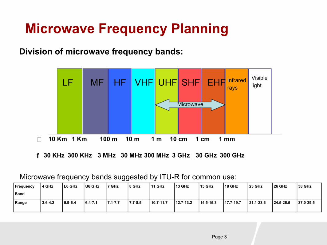
Microwave frequency bands suggested by ITU-R for common use:Frequency
Band
4 GHz L6 GHz U6 GHz 7 GHz 8 GHz 11 GHz 13 GHz 15 GHz 18 GHz 23 GHz 26 GHz 38 GHz
Range 3.6-4.2 5.9-6.4 6.4-7.1 7.1-7.7 7.7-8.5 10.7-11.7 12.7-13.2 14.5-15.3 17.7-19.7 21.1-23.6 24.5-26.5 37.0-39.5
Microwave Frequency PlanningDivision of microwave frequency bands:
LF MF HF VHF UHF SHF EHF
Microwave
� 10 Km 1 Km 100 m 10 m 1 m 10 cm 1 cm 1 mm
f 30 KHz 300 KHz 3 MHz 30 MHz 300 MHz 3 GHz 30 GHz 300 GHz
Infrared rays
Visible light

Page 4
Microwave Frequency PlanningPrinciples of selecting proper frequency bands:
1. Select proper frequency bands according to the frequency resources (licenses) owned by the carriers and the stipulations of local radio management committees.
2. Select proper frequency bands according to the characteristics of the designed networks and routes. For example, high-frequency bands are generally used for mobile networks and MANs because quite a few channels available at high-frequency bands.
3. Select proper frequency bands according to their characteristics.
● Low-frequency bands (L6G/U6G/7G/8G/11G) are suitable for long-distance links and high-frequency bands (13G/15G/18G/23G/26G/38G) are suitable for short-distance links.
● Due to the limited number of channels existing at low-frequency bands, interference tends to arise in the long-distance transmission.
● High-frequency bands are suitable for high-speed data transmission and interference sustainable because there are many channels with broad bandwidth.
● High-frequency antennas feature high gains. Compared with low-frequency bands, high-frequency bands require small clearance. Towers with these antennas properly used can be lower than others.

Page 5
Microwave Frequency Planning
Illustration of the selection of microwave frequency bands:
85432 10 201 30 40 50
1.5 2.5LAN/PCS
Long-distance backbone networks
Area, local, and edge networks
28
34Mbit/s
34140155
Mbit/s
28
34140155
Mbit/s
3.3 11 GHz
GHz
Page 6
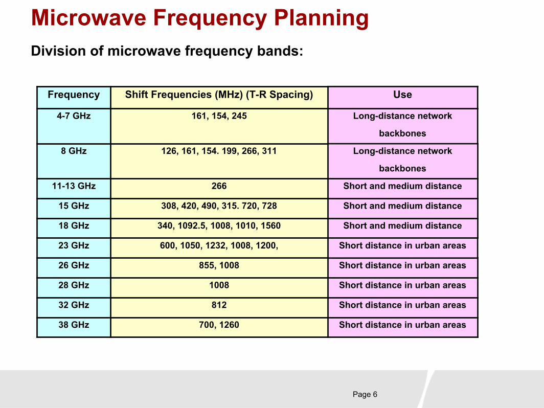
Microwave Frequency PlanningDivision of microwave frequency bands:
Frequency Shift Frequencies (MHz) (T-R Spacing) Use
4-7 GHz 161, 154, 245 Long-distance network
backbones
8 GHz 126, 161, 154. 199, 266, 311 Long-distance network
backbones
11-13 GHz 266 Short and medium distance
15 GHz 308, 420, 490, 315. 720, 728 Short and medium distance
18 GHz 340, 1092.5, 1008, 1010, 1560 Short and medium distance
23 GHz 600, 1050, 1232, 1008, 1200, Short distance in urban areas
26 GHz 855, 1008 Short distance in urban areas
28 GHz 1008 Short distance in urban areas
32 GHz 812 Short distance in urban areas
38 GHz 700, 1260 Short distance in urban areas
Page 7
Microwave Frequency Planning
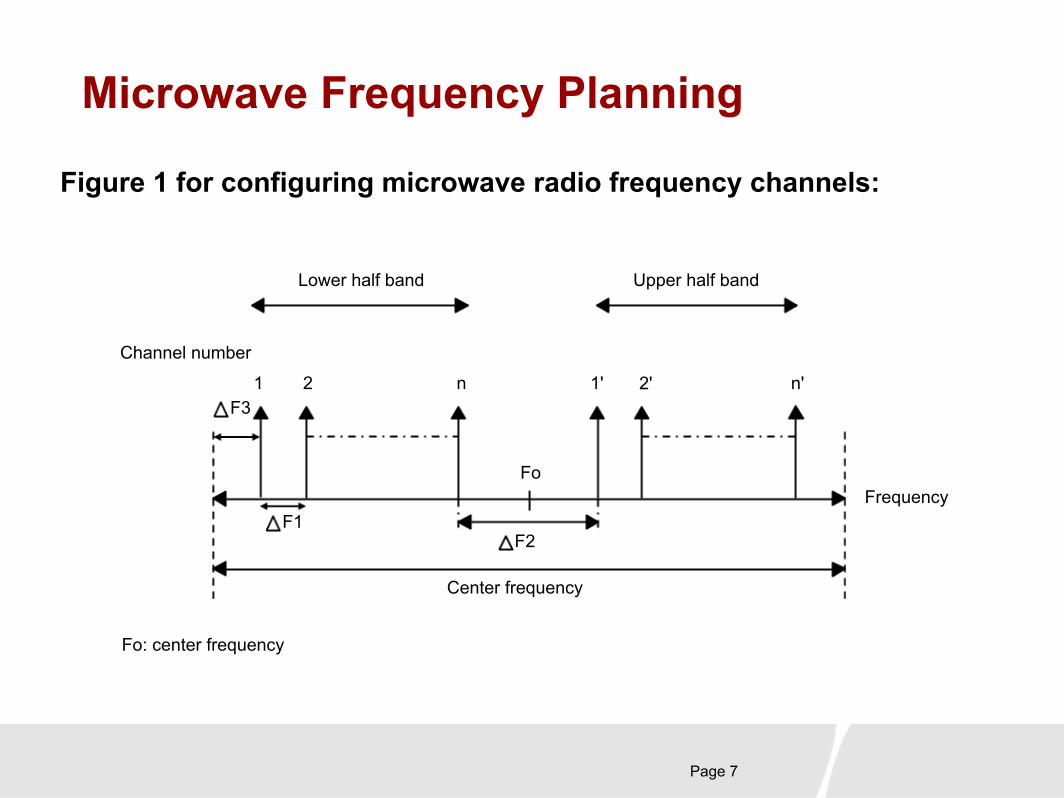
Figure 1 for configuring microwave radio frequency channels:
Channel number
Frequency
F3
F1F2
Fo
1 2 n 1' n'
Lower half band Upper half band
Center frequency
Fo: center frequency
2'
Page 8
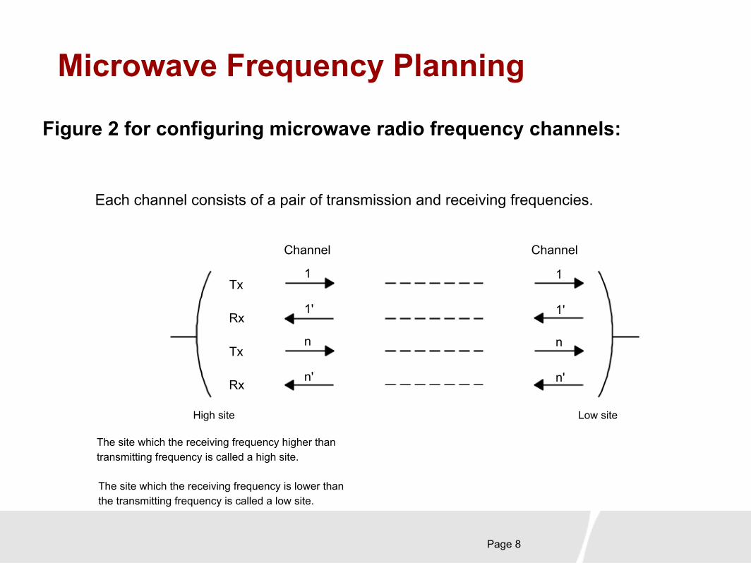
Microwave Frequency Planning
Figure 2 for configuring microwave radio frequency channels:
Each channel consists of a pair of transmission and receiving frequencies.
Tx
Rx
Tx
Rx
Channel Channel
1
1'
n
n'
1
1'
n
n'
High site Low site
The site which the receiving frequency higher than transmitting frequency is called a high site.
The site which the receiving frequency is lower than the transmitting frequency is called a low site.
Page 9
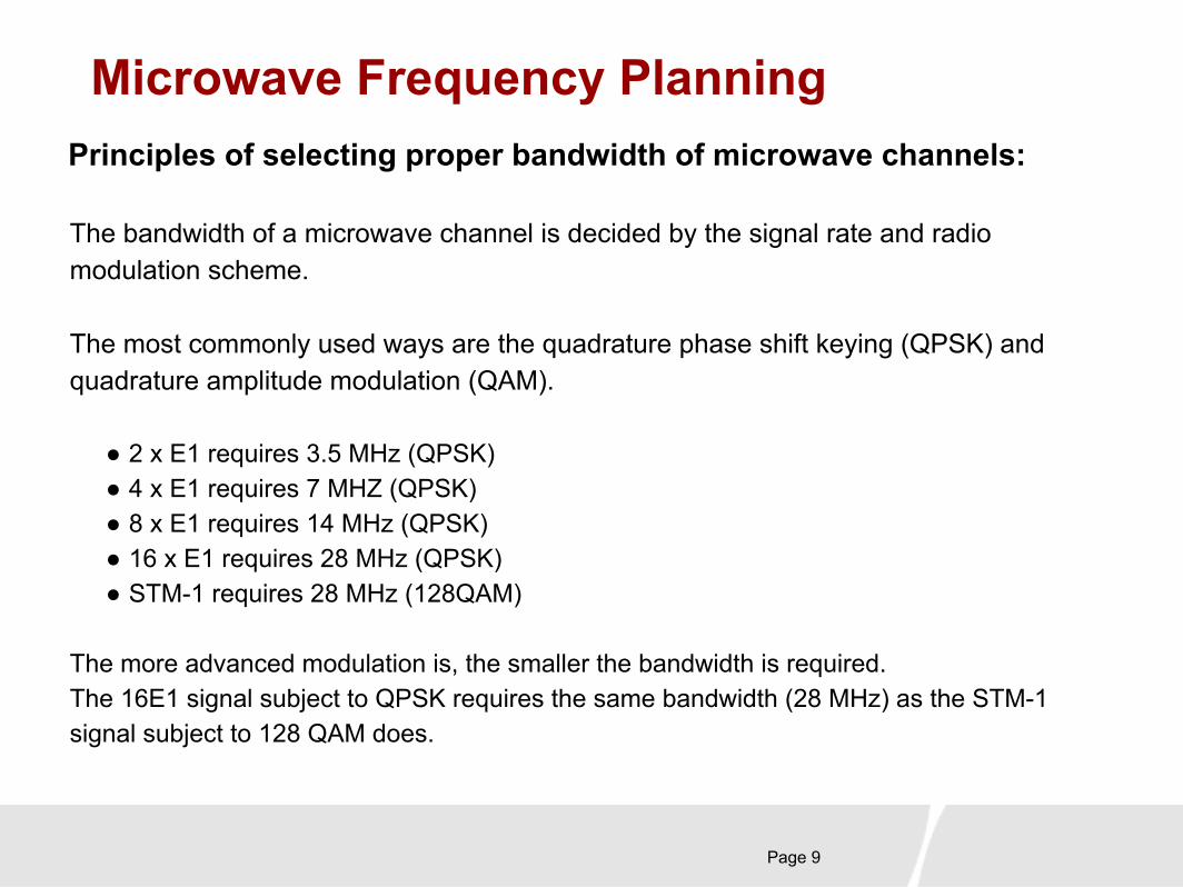
Microwave Frequency PlanningPrinciples of selecting proper bandwidth of microwave channels:
The bandwidth of a microwave channel is decided by the signal rate and radio modulation scheme.
The most commonly used ways are the quadrature phase shift keying (QPSK) and quadrature amplitude modulation (QAM).
● 2 x E1 requires 3.5 MHz (QPSK)● 4 x E1 requires 7 MHZ (QPSK)● 8 x E1 requires 14 MHz (QPSK)● 16 x E1 requires 28 MHz (QPSK)● STM-1 requires 28 MHz (128QAM)
The more advanced modulation is, the smaller the bandwidth is required. The 16E1 signal subject to QPSK requires the same bandwidth (28 MHz) as the STM-1 signal subject to 128 QAM does.

Page 10
Microwave Frequency PlanningPrinciples of selecting proper microwave
channels:1. Try not to select the special frequency resources (licensed) used by other carriers even if these frequency bands are not used in some areas (in case they may be used in the future).
2. If the planned microwave link features the same routing or parallel routing as another microwave link, it is recommended that the frequency band/channels different from those of the existing link are used. A different polarization mode should be configured even if the same channel is adopted as a result of the little interference and big margin proved by the calculation and analysis.
3. If the angle between two interleaving routes is comparatively small (for example, smaller than 30 degrees), a different channel should be selected. If the angle is quite large (for example, larger than 60 degrees), the same channel can be used provided a different polarization mode is configured. The same channel with the same polarization mode can be used only when the angle is larger than 90 degrees. This is a generally adopted principle for microwave frequency planning. For different equipment, antenna configuration, or capacity, analysis should be made on the link accordingly.
4. In the design, the microwave link should be as far from the scatter communication station and the satellite communications earth station as possible. When the antenna of the microwave station is directed to the satellite orbit with a tolerance of ±2 degrees, the frequency band of the communication satellite cannot be used.
Page 11
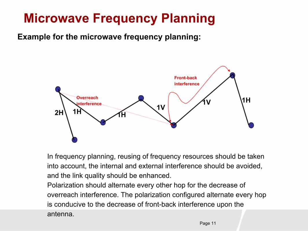
Microwave Frequency PlanningExample for the microwave frequency planning:
In frequency planning, reusing of frequency resources should be taken into account, the internal and external interference should be avoided, and the link quality should be enhanced. Polarization should alternate every other hop for the decrease of overreach interference. The polarization configured alternate every hop is conducive to the decrease of front-back interference upon the antenna.
1H 1H1V
1V2H
1HOverreach interference
Front-back interference

Page 12
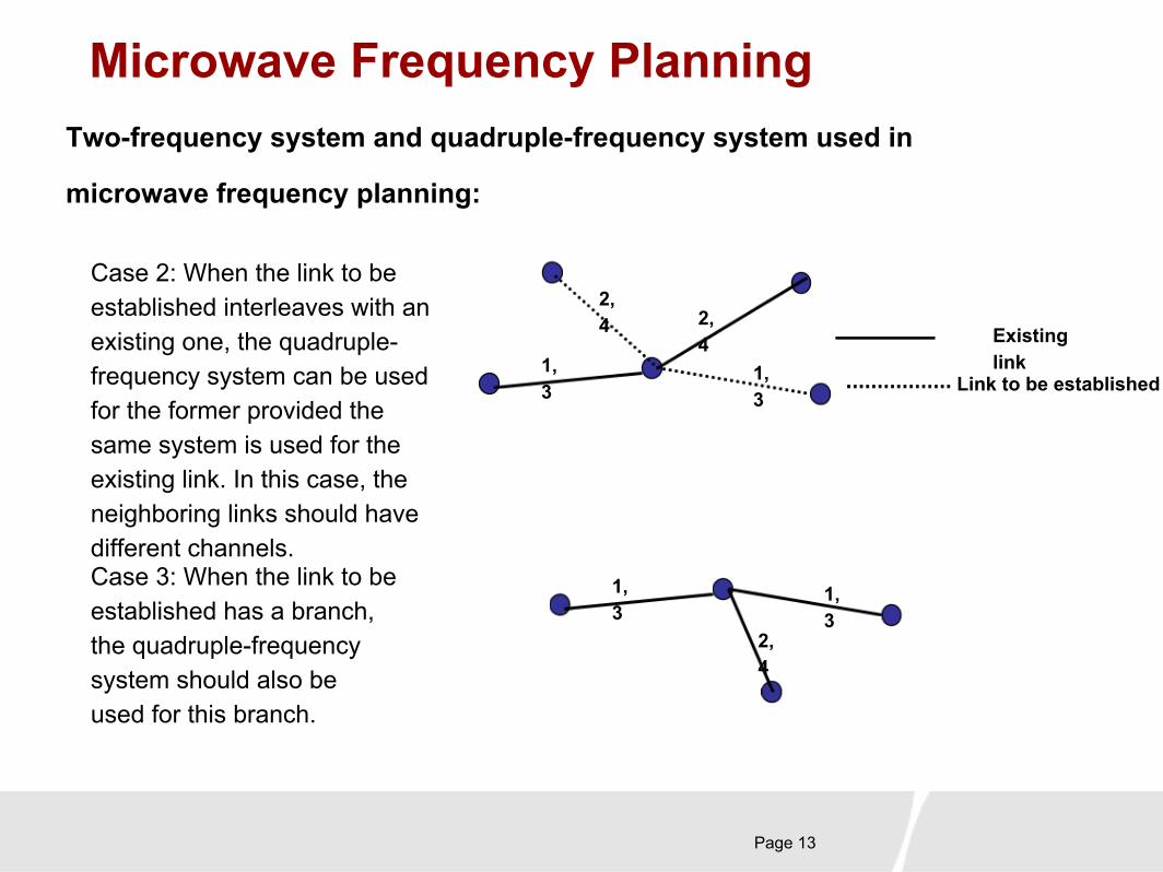
Microwave Frequency PlanningTwo-frequency system and quadruple-frequency system used
in microwave frequency planning:
For the 1+1 system or 2+0 system of the frequency diversity, the use of the two-frequency system can save the frequency resources, while the use of the quadruple-frequency system can decrease the internal and external interference and enhance the link quality. Whether to select the two-frequency system or the quadruple-frequency system depends on the interference within the planned microwave network system and the mutual interference between the microwave links to be established and the links existing in the system.
Case 1: When the link to be established interleaves with an existing one, the two-frequency system can be used for the former provided the same system is used for the existing link, and a different channel should be selected in this case.
Existing link
Link to be established
1,3
1,3
2,4
2,4
Page 13
Microwave Frequency PlanningTwo-frequency system and quadruple-frequency system used in
microwave frequency planning:
Case 2: When the link to be established interleaves with an existing one, the quadruple-frequency system can be used for the former provided the same system is used for the existing link. In this case, the neighboring links should have different channels.
Existing link
Link to be established1,3
2,4
2,4
1,3
Case 3: When the link to be established has a branch, the quadruple-frequency system should also be used for this branch.
1,3
2,4
1,3

Page 14
Microwave Frequency PlanningTwo-frequency system and quadruple-frequency system
used in microwave frequency planning:
Case 4: When the link to be established forms a loop-line with quite small angles, the quadruple-frequency system should be selected.
1,3
2,4
2,4
Case 5: When the routing deflection angles are too great, but the angles of La and Lb are quite small, for example, smaller than 15 degrees, comparatively great overreach interference may occur if the two-frequency system is selected for Site A and Site D. Therefore, the quadruple-frequency system should also be used in this case.
1,3
1,3
1,3
AB
C
D
2,4
La
Lb
Case 6: The quadruple-frequency system should also be selected in such circumstances as the front-back ratio difference of the antenna is smaller than 60dB, the SWR(Standing Wave Ratio) of the antenna feeder is large, and the equipment has weak immunity to interference.
Page 15
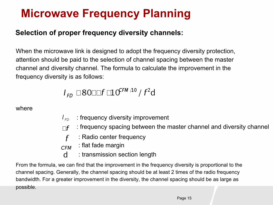
Microwave Frequency PlanningSelection of proper frequency diversity channels:
When the microwave link is designed to adopt the frequency diversity protection, attention should be paid to the selection of channel spacing between the master channel and diversity channel. The formula to calculate the improvement in the frequency diversity is as follows:
where: frequency diversity improvement: frequency spacing between the master channel and diversity channel: Radio center frequency: flat fade margin: transmission section length
From the formula, we can find that the improvement in the frequency diversity is proportional to the channel spacing. Generally, the channel spacing should be at least 2 times of the radio frequency bandwidth. For a greater improvement in the diversity, the channel spacing should be as large as possible.

Page 16
Case Study for Microwave Frequency Planning
Case study purpose: to be familiar with the preceding rules for microwave frequency
planning and apply them to practice.Project area: Mauritius in the Eastern Hemisphere and Southern Hemisphere
Requirement of the longitude
and latitude of the site:
Frequency resource: assigned by the user, 7G/28M: 2 chs; 8G/7M: 4 chs
Contents of planning:
● Channel
planning● High and low sites configuration
● Configuration of the polarization mode for the channel
GSM Network frequency planning in Mauritius:

Page 17
Case Study for Microwave Frequency Planning
Legend:
Complete the routing and capacity planning by referring to the
right map:
STM-1
8E1
4E1
New relay stations
Service hub
BTS

Page 18
Case Study for Microwave Frequency Planning
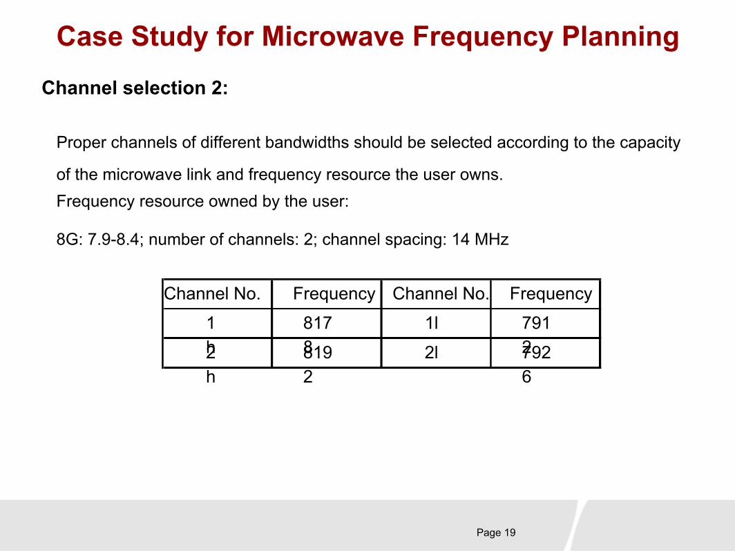
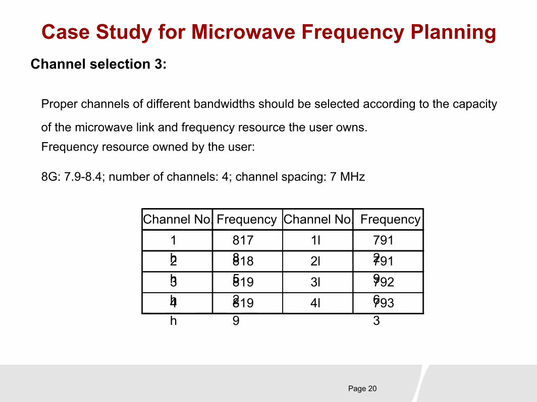
Proper channels of different bandwidths should be selected according to the capacity of
the microwave link and frequency resource the user owns.Frequency resource owned by the user:
Channel selection 1:
Channel No. Frequency Channel No. Frequency
1h
7610
1l 7442
3h
7666
3l 7498
7G: 7.4-7.7; number of channels: 2; channel spacing: 28 MHz
Page 19
Case Study for Microwave Frequency Planning
Proper channels of different bandwidths should be selected according to the capacity
of the microwave link and frequency resource the user owns.Frequency resource owned by the user:
Channel selection 2:
8G: 7.9-8.4; number of channels: 2; channel spacing: 14 MHz
Channel No. Frequency Channel No. Frequency
1h
8178
1l 79122
h8192
2l 7926
Page 20
Case Study for Microwave Frequency Planning
Proper channels of different bandwidths should be selected according to the capacity
of the microwave link and frequency resource the user owns.Frequency resource owned by the user:
Channel selection 3:
8G: 7.9-8.4; number of channels: 4; channel spacing: 7 MHz
Channel No. Frequency Channel No. Frequency 1h
8178
1l 79122
h8185
2l 79193
h8192
3l 79264
h8199
4l 7933

Page 21
Case Study for Microwave Frequency Planning
Proper channels of different bandwidths should be selected according to the capacity
of the microwave link and frequency resource the user owns.The following channels are selected according to the capacity of the link:
Channel selection 4:
For STM-1, select f1 and f3 channels (7425-7725) with 28 MHz bandwidth.
For 8E1 PDH, select f1 and f2 channels (7900-8400) with 14 MHz bandwidth.
For 4E1 PDH, select f1, f2, f3, and f4 channels (7900-8400) with 7MHz bandwidth.

Page 22
Case Study for Microwave Frequency Planning
Implement the frequency planning in Pathloss by using the preceding rules flexibly.
Points to be noted in frequency planning:
Frequency planning in Pathloss:
1. All microwave sites must clearly mark the CALL SIGN, which cannot be the
same and will be used in the later interference calculation.
2. Two-frequency system. To prevent the co-channel interference, a site should
use different channels for multi-directions.
3. Deploy the sites in such a way as high sites and low ones alternate. Check the
interference calculation report to see whether this principle is observed.
4. Configure the sites with two polarization modes as required.

Page 23
Case Study for Microwave Frequency Planning
Example for frequency planning in Pathloss:
Frequency planning in Pathloss:
1. Access the PL4.0 program.
2. Log in to the network module.
3. Open the completed routing file.
4. Take the link between Site 5 and Site 21 for instance. Set the CH parameters
after setting the parameters for Radio and Antennas.
5. Click CH. The TX Channels dialog box is displayed, as shown in the next page.

Page 24
Case Study for Microwave Frequency Planning
Click CH. The TX
Channels dialog box
is displayed, as
shown in the figure
on the right side :
Frequency planning in Pathloss:

Page 25
Case Study for Microwave Frequency Planning
Click Lookup. In
the File dialog box
that is displayed,
click Open and
select the
corresponding
frequency planning
file from Freqplan,
as shown in the
figure on the right
side.
Frequency planning in Pathloss:

Page 26
Case Study for Microwave Frequency Planning
Open the target
frequency planning
file, as shown in
the figure on the
right side :
Frequency planning in Pathloss:
Page 27
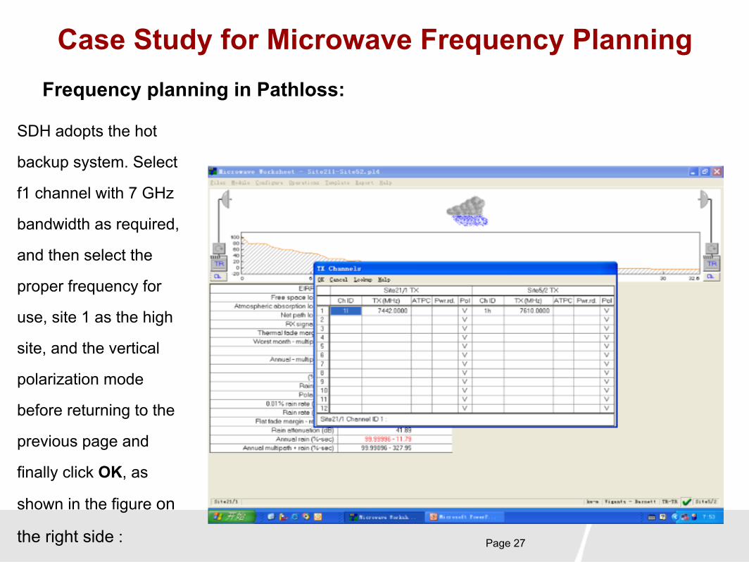
Case Study for Microwave Frequency Planning
SDH adopts the hot
backup system. Select
f1 channel with 7 GHz
bandwidth as required,
and then select the
proper frequency for
use, site 1 as the high
site, and the vertical
polarization mode
before returning to the
previous page and
finally click OK, as
shown in the figure on
the right side :
Frequency planning in Pathloss:
Page 28
Case Study for Microwave Frequency Planning
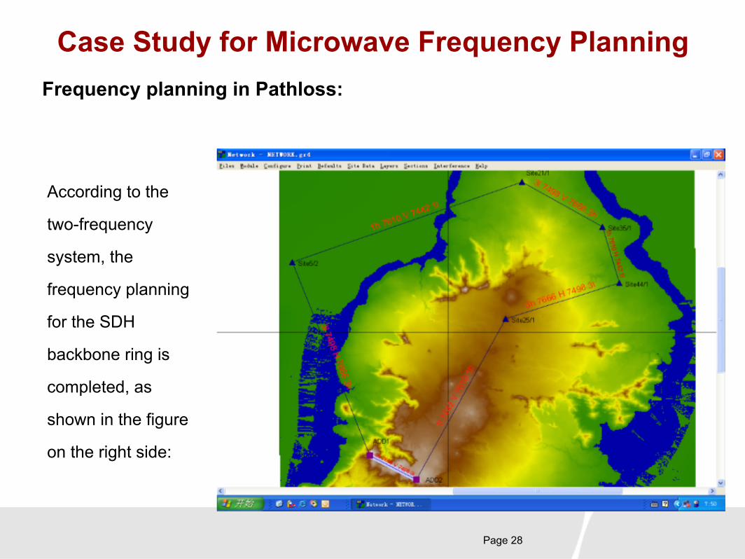
According to the
two-frequency
system, the
frequency planning
for the SDH
backbone ring is
completed, as
shown in the figure
on the right side:
Frequency planning in Pathloss:

Page 29
Case Study for Microwave Frequency Planning
According to the two-frequency
system, the frequency planning
for the SDH backbone ring is
completed, as shown in the
figure on the right side.
Note that a site (Site 5) in the
ring has both high and low
stations due to the odd number
of the BTSs. In frequency
planning processes, this
should be avoided.
Frequency planning in Pathloss:
3l 7498 H 7666 3h
3l 7498 V 7666 3h1h 7610 V 7442 1l
3h 7666 H 7498 3l
1l 7442 V 7610 1h
1h 7610 H 7442 1l
3h 7666 V 7498 3l
Site 5/2
Site 21/1
Site 25/1
Site 44/1
Site 35/1
ADD1
ADD2

Page 30
Case Study for Microwave Frequency Planning
Statistics about the
frequency planning
for the SDH
backbone ring:
Frequency planning in Pathloss:
Site Name 1 Site Name 2Frequency/Polarization
Mode
Site 5 (high) Site 21 (low) 1/V
Site 21 (low) Site 35 (high) 3/V
Site 35 (high) Site 44 (low) 1/H
Site 44 (low) Site 25 (high) 3/H
Site 25 (high) ADD 2 (low) 1/V
ADD 2 (low) ADD 1 (high) 3/V
ADD 1 (high) Site 5 (low) 3/H
Page 31
Case Study for Microwave Frequency Planning
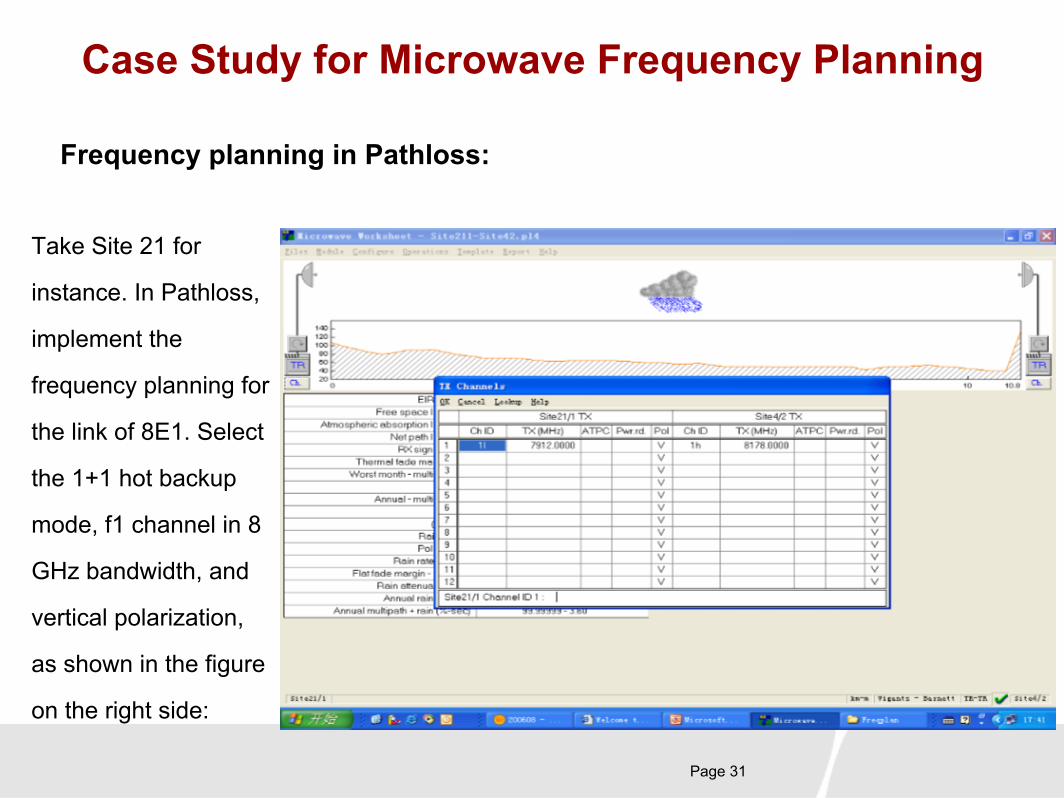
Take Site 21 for
instance. In Pathloss,
implement the
frequency planning for
the link of 8E1. Select
the 1+1 hot backup
mode, f1 channel in 8
GHz bandwidth, and
vertical polarization,
as shown in the figure
on the right side:
Frequency planning in Pathloss:

Page 32
Case Study for Microwave Frequency Planning
Take Site 21 for
instance. The result
of the frequency
planning for the link
of 8E1 is shown in
the figure on the
right side:
Frequency planning in Pathloss:
8E1 frequency configuration

Page 33
Case Study for Microwave Frequency Planning
Take Site 21 for
instance. The result
of the frequency
planning for the link
of 4E1 is shown in
the figure on the
right side:
Frequency planning in Pathloss:

Page 34
Case Study for Microwave Frequency Planning
The 2-hop SDH link, 1-hop 8E1 link,
and 3-hop 4E1 link converge at Site
21. As 4E1 has quite a few links, try
to select different channels in the
direction of 8E1 links to reduce the
interference. In this case, f1, f3, and
f4 channels with 8 GHz bandwidth
are selected and a different
polarization mode is adopted. The
statistics about the frequency
planning for Site 21 are listed in the
table on the right side:
Frequency planning in Pathloss:
Site
Names 1
Site
Names 2
Equipment Planned
Frequency
T R
Site 21
(low)
Site 8
(high)
4E1 4H 7933 8199
Site 21
(low)
Site 38
(high)
4E1 3V 7926 8192
Site 21
(low)
Site 39
(high)
4E1 1H 7912 8178

Page 35
Case Study for Microwave Frequency Planning
The result of the
frequency
planning for Site
21 is shown in
the figure on the
right side:
Frequency planning in Pathloss:
Site 5
Site 21
Site 351h 7610 V 7442 1l 3l 7498 V 7666 3h
3h 8192 V 7926 3l
1h 8178 V 7912 1l 8E1-4PSK
1h 8178 H 7912 1l
4h 8199 H 7933 4l
Site 8
Site 38
Site 39

Page 36
Case Study for Microwave Frequency Planning
The reference result of
the frequency planning
is shown in figure on
the right side.
Frequency planning in Pathloss:
Note:
H---F1 V---L
H/L indicates the high/low site.
F1 indicates the SDH frequency; f1 indicates the PDH frequency; V indicates the polarization mode.

Page 37
Case Study for Microwave Frequency Planning
Complete all frequency planning for the microwave network according to
the relevant principles and output the design result. The frequency
configuration in the software will be used for the future interference
analysis.
Frequency planning in Pathloss: