
MVT/VSE Initialization Guide - Software Pursuits
158
MVT/VSE Initialization Guide Release 9.5 M309-0501
Transcript of MVT/VSE Initialization Guide - Software Pursuits

MVT/VSE Initialization Guide
Release 9.5 M309-0501

This contains confidential and trade secret material of Software
Pursuits, Inc. The contents of this document must not be distributed to unauthorized parties.
Copyright © 2006 by Software Pursuits, Inc. All Rights Reserved.
Last Revision: June 12, 2006
Document Name: MVTINIT.DOC

Table of Contents
Chapter 1 Introduction..........................................................................7
Additional Publications.......................................................................................... 7
Chapter 2 System Considerations ........................................................9
System Expiration .................................................................................................. 9 Using Supervisor Tables ........................................................................................ 9
LUB Table ............................................................................................................................... 9 "BG" COMREG Usage............................................................................................................ 9 TIMER Ownership................................................................................................................. 10
Non-LIBR/LIBR Library Migration .................................................................... 10 Multiple Logical Transient Areas (LTA)............................................................. 12 SVA and SDL Considerations ............................................................................. 12 MVT/VSE Subtask Support................................................................................. 13 Hardware .............................................................................................................. 14
Multi-path Devices................................................................................................................. 14 Shared Control Unit End (CUE) ............................................................................................ 14 Use Of RPS (Rotational Position Sensing) With MVT/VSE................................................. 14
Access Methods ................................................................................................... 16 VSAM.................................................................................................................................... 16 BTAM.................................................................................................................................... 16 ISAM ..................................................................................................................................... 16 OPEN For Sequential And Direct Access Files..................................................................... 17
Named ENQ And Cross-region Communication................................................. 18 ENQ ....................................................................................................................................... 20 DEQ ....................................................................................................................................... 21 ENQRELSE ........................................................................................................................... 21 Posting ECB's For Another Region ....................................................................................... 22
Standard ENQ.......................................................................................................... 22 Named ENQ ............................................................................................................ 23 ENQ Without A Wait .............................................................................................. 23 Cross Region Communication ................................................................................. 24 Cross Region Communication ................................................................................ 25 Cross Region Communication ................................................................................. 26
Chapter 3 Installation ..........................................................................29
Planning For Installation......................................................................................... 30
Installation Timetable .......................................................................................... 30 Software Compatibility ........................................................................................ 30
MVT/VSE Initialization Guide Page i

Features unique to MVT/VSE ............................................................................................... 31 Unsupported Features ............................................................................................................ 31
Virtual Machine Support......................................................................................31 MVT/VSE And VM Handshaking ........................................................................................ 32 VM Considerations ................................................................................................................ 32
Performance............................................................................................................. 32 Online Vs. Batch Guest Machines........................................................................... 33 Setting VM Guest Performance Options ................................................................. 34 The MVT/VSE Nucleus Under VM........................................................................ 34 Device Support Under VM...................................................................................... 34 SPOOL Use Under VM........................................................................................... 35 The VM Directory ................................................................................................... 36
USER Statement............................................................................................... 36 OPTION Statement .......................................................................................... 37 IPL Statement ................................................................................................... 37 CONSOLE Statement....................................................................................... 37 Additional Notes On Consoles ......................................................................... 38 SPOOL Statement ............................................................................................ 39 SPECIAL Statement......................................................................................... 40 DEDICATE Statement ..................................................................................... 41 MDISK Statement ............................................................................................ 41 LINK Statement ............................................................................................... 42
An MVT/VSE Profile EXEC................................................................................................. 43 Additional Considerations ..................................................................................................... 44
Hardware Compatibility..........................................................................................46
Installing MVT/VSE ................................................................................................47
Installation Disk Space Allocations .....................................................................47 Program Size Considerations ...............................................................................48 Customizing Procedures.......................................................................................49
Chapter 4 The MVT/VSE Nucleus..................................................... 51
Generating The MVT/VSE Nucleus .......................................................................51
Generating An Alternate Nucleus...........................................................................53
Specifying MVT/VSE Nucleus Options..................................................................54
Summary Of MVT/VSE Nucleus Macros............................................................54
NUCASSGN..............................................................................................................55
Operands/Options.................................................................................................55 Key Points ............................................................................................................55 Examples ..............................................................................................................56
NUCDEV...................................................................................................................57
Operands/Options.................................................................................................57 Key Points ............................................................................................................59
Page ii MVT/VSE Initialization Guide

Examples .............................................................................................................. 59
NUCEND................................................................................................................... 60
Operands/Options................................................................................................. 60
NUCOPTN1.............................................................................................................. 62
Operands/Options................................................................................................. 63
NUCOPTN2.............................................................................................................. 65
Operands/options ................................................................................................. 66
NUCOPTN3.............................................................................................................. 69
Operands/Options................................................................................................. 71
Use Of XTRAPUB In The Nucleus Assembly ....................................................... 77
Editing Macros ......................................................................................................... 77
Chapter 5 Initial Program Load.........................................................79
The IPL Sequence .................................................................................................... 79
Automatic IPL...................................................................................................... 80 The $IPLPROC Procedure................................................................................... 85
Other Types Of IPLs................................................................................................ 86
Interrupted IPL..................................................................................................... 86
MVT/VSE IPL Statements ...................................................................................... 87
Usage Notes ......................................................................................................... 87 .* (Comment) ....................................................................................................... 88
Examples................................................................................................................................ 88
ADD ..................................................................................................................... 89 Operands/Options .................................................................................................................. 89 Key Points.............................................................................................................................. 90 Examples................................................................................................................................ 92
ASSGN................................................................................................................. 94 Operands/Options .................................................................................................................. 94
BRANCH ............................................................................................................. 96 Operands/Options .................................................................................................................. 96 Key Points.............................................................................................................................. 96 Examples................................................................................................................................ 97
DEFINE................................................................................................................ 98 Operands/Options .................................................................................................................. 99 Key Points............................................................................................................................ 101 Examples.............................................................................................................................. 102
DELETE............................................................................................................. 104 Operands/Options ................................................................................................................ 104
MVT/VSE Initialization Guide Page iii

Examples.............................................................................................................................. 104
DLA....................................................................................................................105 Operands/Options ................................................................................................................ 105 Key Points............................................................................................................................ 106
DLF ....................................................................................................................109 Operands/Options ................................................................................................................ 109 Key Points............................................................................................................................ 110
DPD....................................................................................................................112 Operands/Options ................................................................................................................ 112 Key Points............................................................................................................................ 113 Examples.............................................................................................................................. 114
INPUT ................................................................................................................115 Operands/Options ................................................................................................................ 115 Examples.............................................................................................................................. 115
NUCLEUS..........................................................................................................117 Operands/Options ................................................................................................................ 117 Key Points............................................................................................................................ 117 Examples.............................................................................................................................. 117
OPTION .............................................................................................................119 Operands/Options ................................................................................................................ 120 Key Points............................................................................................................................ 125 Examples.............................................................................................................................. 126
PROCEDUR.......................................................................................................128 Operands/Options ................................................................................................................ 128
SET.....................................................................................................................129 Operands/Options ................................................................................................................ 129
STOP ..................................................................................................................131 Operands/Options ................................................................................................................ 131
SVA....................................................................................................................133 Operands/Options ................................................................................................................ 133
SYSLOG ............................................................................................................134 Operands/Options ................................................................................................................ 134 Key Points............................................................................................................................ 134
Appendix A Examples of IPLStatements Use................................. 135
VAE Mode...............................................................................................................136
VAE Mode Under VM ...........................................................................................137
VAE Mode...............................................................................................................138
VAE Mode...............................................................................................................139
VM Mode ................................................................................................................140
Appendix B Supported Device Types .............................................. 141
Page iv MVT/VSE Initialization Guide

Communications Devices....................................................................................... 142
Consoles And Terminals........................................................................................ 143
DASD Devices ......................................................................................................... 144
MICR Devices......................................................................................................... 145
Printer Devices ....................................................................................................... 146
Reader/Punch Devices ........................................................................................... 147
Tape Devices ........................................................................................................... 148
Miscellaneous Devices............................................................................................ 149
Unsupported Devices ............................................................................................. 150
Index 151
MVT/VSE Initialization Guide Page v


Chapter 1 - Introduction
MVT/VSE Initialization Guide Page 7
Chapter 1 Introduction
This publication is a guide to the general system considerations for the MVT/VSE operating system. This publication is intended for those persons responsible for the installation, maintenance, and to some extent, the operation of the MVT/VSE system.
This publication assumes the reader has some familiarity with DOS based systems and the hardware on which this type of system operates. Readers who are not familiar with these areas should first gain a basic understanding of Data Processing and the fundamentals involved in the installation, maintenance, and operation of VSE operating systems.
This includes:
• Chapter 2 - System Considerations: A discussion of the overall general considerations when installing and using the MVT/VSE operating system.
• Chapter 3 - Installation: This chapter is concerned with the actual installation of the MVT/VSE operating system.
• Chapter 4 - The MVT/VSE Nucleus: This chapter addresses the MVT/VSE nucleus. It covers the different nucleus options and the methods of generating the nucleus.
• Chapter 5 - Initial Program Load: A discussion of the Initial Program Load procedures and the different types of IPL that may be performed. This chapter also describes the different IPL statements and their use.
Additional Publications
The following MVT/VSE publications are available and may be required during the initialization of the system:
• MVT/VSE System Control (M409)
• MVT/VSE System Management Guide (M509)
• MVT/VSE Utilities And Macros (M609)


Chapter 2 - System Considerations
Chapter 2 System Considerations
This section is devoted to the general and specific considerations for the proper operation of the MVT/VSE operating system. It addresses the general hardware and software compatibility areas as well as the concerns for controlling jobs within the MVT/VSE system.
System Expiration
The MVT/VSE operating system is "leased" to an SPI customer for a specific period of time. As a result, MVT/VSE incorporates an expiration system to warn the customer when that lease period is about to end.
SPI provides an "expiration update" procedure that resets the system to allow continued use. Additional information on this expiration system is available from SPI.
Using Supervisor Tables
The supervisor tables in MVT/VSE are compatible with those of DOS/VSE, provided strict rules for locating the tables are used. When using a supervisor table, code your program to be compatible with DOS, DOS/VS, and DOS/MVT. Try not to use any field which is unique to an operating system.
LUB Table
Each region has its own LUB table. The address of each region's LUB table is contained in its corresponding COMRG. The index to the first system LUB is always zero while the index to the first programmer LUB is always equal to the system NICL count. To remain compatible with other operating systems it is recommended that the FICL indexes still be used.
"BG" COMREG Usage
To avoid problems in locating the proper LUB tables, the "BG" COMREG address in each COMREG gives the address of the current COMREG instead of a different COMREG address.
MVT/VSE Initialization Guide Page 9

Chapter 2 - System Considerations
TIMER Ownership
Since all tasks may use the timer under MVT/VSE, the ID of the timer owner is not used. To avoid compatibility problems with software products which verify the ownership of the timer, each COMREG will indicate that the current task is the owner of the timer.
Non-LIBR/LIBR Library Migration
MVT/VSE supports the use of Non-LIBR format library names for its' LIBR version. This allows the user to use existing JCL when a Non-LIBR version of MVT/VSE is replaced with a version that supports the LIBR function.
This function is only valid for library search chains and CATALOG (TO=) for LNKEDT. This support is provided via a library migration table. The table contains the names of old format libraries and their associated new (LIBR) format names. The table must be assembled and placed in the SVA before it may be used. Assembly is done using the INLMIGR macro.
For the JCP example below, the following libraries are being defined and will be converted if the old name is used on a LIBDEF statement: OLD LIBRARY NEW LIBRARY/SUBLIBRARY PGMOLD1 PGMLIB1.PGMNEW1 PGMOLD2 PGMLIB2.PGMNEW1 PGMOLD3 PGMLIB3.PGMNEW1 PGMOD11 PGMLIB2.PGMNEW2 PGMOD20 PGMLIB3.PGMNEW3
Page 10 MVT/VSE Initialization Guide

Chapter 2 - System Considerations
The following is an example of the job used to create the INLMIGR migration table. Please note the following: • The INLMIGR macro will automatically generate a phase name of INLPLMT for the assembly. • The INLMIGR macro must begin in column 10.
// JOB CRLIBTAB LIBDEF PHASE,CATALOG=lib.sublib // OPTION CATAL // EXEC ASSEMBLY INLMIGR OLD=PGMOLD1,LIB=PGMLIB1,SUBLIB=PGMNEW1 INLMIGR OLD=PGMOLD2,LIB=PGMLIB2,SUBLIB=PGMNEW1 INLMIGR OLD=PGMOLD3,LIB=PGMLIB3,SUBLIB=PGMNEW1 ... INLMIGR OLD=PGMOD11,LIB=PGMLIB2,SUBLIB=PGMNEW2 ... INLMIGR OLD=PGMOD20,LIB=PGMLIB3,SUBLIB=PGMNEW3 ... INLMIGR OLD=IJSYSRS,LIB=IJSYSRS,SUBLIB=SYSLIB END /* // EXEC LNKEDT LIBDEF PHASE,SEARCH=lib.sublib SET SDL INLPLMT,SVA /* /&
The last entry in the above sample shows IJSYSRS being included for the standard IJSYSRS.SYSLIB library. This is required for those jobs that specifically use the old format LIBDEF with IJSYSRS specified.
Using the above conversion table, assume the following old JCL LIBDEF format:
// LIBDEF CL,SEARCH=PGMOLD1,TO=PGMOLD1
This statement would be converted to:
// LIBDEF PHASE,SEARCH=PGMLIB1.PGMNEW1,CATALOG=PGMLIB1.PGMNEW1
Also the following:
// LIBDEF SL,SEARCH=PGMOD11
MVT/VSE Initialization Guide Page 11

Chapter 2 - System Considerations
Would be converted to:
// LIBDEF SOURCE,SEARCH=PGMLIB2.PGMNEW2
Multiple Logical Transient Areas (LTA)
MVT/VSE supports multiple logical transient areas (LTA's). Specify 3 or 4 in your nucleus options assembly. It is not necessary to specify one per region since they are pooled. Each requires 2K of memory. MVT/VSE automatically coordinates transients which cannot tolerate other versions of the same transient running. Those products and routines are handled automatically. The system also assumes that transients which are not recognized by the system will only be allowed to run one copy at a time.
If you are using a special product which appears to have too much LTA wait time, please inform us so that better support might be possible.
Note: Most tape and disk management systems do not allow themselves to be executed more than once at a time. This generally does not cause a problem since these products also usually allow their LTA to be freed when waiting on a console reply from the operator.
SVA and SDL Considerations
SVA eligible phases may be loaded into the SVA from SYSRES or from a private library and non-SVA eligible phases residing in either SYSRES or a private library may be placed into the SVA in "move" mode or have a directory entry placed in the SDL. Once an entry is placed in the SDL it cannot be updated or changed. The SDL directory is not updated by RESTORE and therefore RESTOREs should not be done to libraries to which directory entries in the SDL refer. If the SDL contains a directory entry for a given private library, then that library cannot be dropped. The system directory list (SDL) may also be specified in a temporary search chain. If both SDL and IJSYSRS are specified, then SDL must come before IJSYSRS. Specifying SDL in the temporary search chain allows the searching of one or more private libraries before the SDL is searched, thereby permitting access to a test version of a program while the SDL has an entry for the production version.
The loading of the SVA or SDL will operate according to the same rules that control program fetching which are as follows:
1. If SDL was specified in the temporary library search chain • The temporary library search chain. The system SVA directory will be searched as specified
by the temporary search chain. • The permanent library search chain. • The system Core Image directory.
Page 12 MVT/VSE Initialization Guide

Chapter 2 - System Considerations
2. If the requested phase name begins with a dollar sign ($) and if SDL was not specified in the temporary library search chain • The system SVA directory. • The system Core Image directory. • The temporary library search chain, if specified. • The permanent library search chain, if specified.
3. If neither of the above conditions is true • The system SVA directory. • The temporary library search chain, if specified. • The permanent library search chain, if specified. • The system Core Image directory.
MVT/VSE Subtask Support
Subtasks under MVT/VSE have all the capabilities of the main task or region task. All programs executing are called tasks, whether they are subtasks, main tasks, or region tasks. There is no distinction between any of these terms except that the region tasks are invoked by job Control, all others are activated by a user's program.
Regions are named R1, R2, R3,..., R9, RA, RB, RC, RD, RE, and RF. Each subtask attached to a region is named S1 through S31, as they are attached. Only fifteen region tasks and a maximum of 208 subtasks may be active in the system at any time. The number of regions and subtasks may be changed at any time through a new nucleus generation.
MVT/VSE Initialization Guide Page 13

Chapter 2 - System Considerations
Hardware
Multi-path Devices
Multi-path devices may be mixed with single path devices on the same controller. The devices must, however, be added in numeric sequence. For each device or set of devices, specify the full set of channel paths or else the single path that is available. Each device must have access to all the same paths as all other devices on the control unit, or they may specify any single path. Any valid path for the other devices on the control unit may be specified.
Shared Control Unit End (CUE)
Some control units handle more than 16 physical addresses. When this occurs, the control unit may present a single control unit end (CUE) interrupt for any of the control unit addresses represented. MVT/VSE is very sensitive to proper presentation of interrupts and if a controller has this condition, it must be signaled to MVT/VSE. To specify shared control unit end interrupts, specify OPTION=SHRCUE on a IPL add statement or on a NUCDEV macro. This needs to be specified only for a control unit address which may not receive a control unit end interrupt. If this is specified when it is not required, only minor system degradation will occur. If not specified when it is actually needed, the system may 'go to sleep' when accessing the control unit. For non-TP devices, the missing interrupt handler will report and correct the error.
OPTION=SHRCUE is not normally needed. The following list shows some of the common situations where it is needed.
• Telecommunications controllers accessing more than one control unit address (more than 16 lines).
• Local CRT controllers accessing more than 16 devices.
• Certain disk configurations which emulate other disk devices and the emulated device addresses have different control unit addresses. The following configurations are known to have the OPTION=SHRCUE requirement: • CDC 33801/33501/33502 disk memory subsystems • 3344 disk type controllers, more than one control unit address is used. • 3310 or 3370 FBA disks when emulating CKD disks. SHRCUE must be specified for all
emulated and native mode addresses. • 3880 controllers that are "plugged" for more than 16 devices.
Use Of RPS (Rotational Position Sensing) With MVT/VSE
Rotational position sensing, or RPS, is a facility used by some disk drive models to allow the channel to be freed while waiting for disk rotation. While this is a hardware feature, the use of the feature requires special channel programs to use the feature. The hardware feature is standard on 3330,
Page 14 MVT/VSE Initialization Guide

Chapter 2 - System Considerations
3330B, 3350, 3375 and 3380 disks. It is optional on 3340 type disks (specified as 3340R). The feature is not available for 2314 or 2311 disks.
System components and most independent system software products will build RPS channel programs automatically whenever the hardware is available. Application programs which use LIOCS must request RPS service in the nucleus. Specifying "RPS=YES" on the NUCOPTN3 macro or "OPTION=RPS" during IPL will trigger the loading of the RPS LIOCS logic modules into the SVA during IPL.
When LIOCS RPS is used, the DTF is extended into the region GETVIS area during DTF OPEN and linkage is made to the RPS Logic Module in the SVA, rather than to the module linked with the program. Not only does this technique permit the use of RPS channel programs, it also allows obsolete versions of logic modules to be replaced without re-linking a program. Block sizes may be increased by placing the buffers in GETVIS space, based on the BLKSIZE= operand on the DLBL statement.
With all the effort made to create RPS channel programs, the use of RPS can still be questionable. Additional CPU time is required to calculate sector addresses and to build the special chains. On slower CPU's this might decrease the total amount of work that can be processed. A mixture of some RPS and some non-RPS channel programs will tend to give faster access to the non-RPS programs. This effect comes about due to the nature of RPS itself.
RPS allows the channel and control unit to start another operation while the disk is rotating to the record desired. On a busy system this can get several devices positioning at once and as a drive reaches its proper position, data transfer begins. But during data transfer, the other disks must spin additional revolutions until the channel is again free. The net effect is to increase the channel busy time, sometimes increase the elapsed time of an I/O operation, but increase the total throughput of the system slightly.
At its best, RPS can allow another channel program to complete while waiting for rotation to the record desired. At its worst, many additional rotations may be needed as other operations complete after the desired position is passed. Since additional CPU processing is involved, it is best to test your environment to see the true effect of RPS.
MVT/VSE Initialization Guide Page 15

Chapter 2 - System Considerations
Access Methods
VSAM
MVT/VSE supports IBM's VSE/VSAM Release 3, program product number 5746-AM2/01, the VSAM Backup/Restore feature, product number 5746-AM2/03 and the Sequential Space Management Feature. These products should be ordered directly from IBM. Many of our users indicated a desire to migrate to this release to use some new features.
BTAM
BTAM has been somewhat modified by Software Pursuits. Therefore all programs and teleprocessing monitors that make use of BTAM must be relinked to include the MVT/VSE BTAM modules. Programs containing the BTMOD and the DTFBT macros must be re-assembled.
An operand is now recognized for DTFBT and BTMOD. That operand is EREPMSG=YES/NO. This operand may be used to suppress BTAM error recovery messages to the console. EREPMSG=YES is assumed if omitted and all BTAM error messages will be output to SYSLOG.
If EREPMSG=NO is specified for a DTFBT macro, messages will be suppressed for that DTF. If EREPMSG=NO is specified for the BTMOD, all BTAM error recovery messages will be suppressed regardless of the DTFBT specifications.
ISAM
MVT/VSE supports ISAM data sets on 3330B, 3350, 3375 and 3380 disk devices. In order to fully implement this support it was necessary to change both LIOCS transients and the ISAM logic modules. Unfortunately, some incompatibilities are created in this process. These incompatibilities have been greatly relaxed in MVT/VSE.
In MVT/VSE new versions of the SETL transients will now recognize the version level of the logic module and will perform the appropriate function. The MVT/VSE logic modules are required if 3330B, 3350, 3375 or 3380 devices are used where data sets cross cylinder addresses which are a multiple of 256. Old IBM logic modules will function as long as these boundaries are not crossed, however, it is permissible to cross the first interval, crossing cylinder number 256. Use of RPS forces the current logic module in the SVA to be used.
If you are running DOS/MVT 7.6 or later, you have already re-linked your ISAM programs and no further change is required. New users, however, must re-link all programs which use sequential ISAM on data sets which will have extents extending beyond cylinder 256. If the data sets are kept below cylinder 256, IBM DOS/VSE and DOS/VSE ISAM logic modules will function correctly. Prior releases should always be re-linked.
Another circumvention of the problem is possible under MVT/VSE if the LIOCS RPS facility is used. If RPS=YES is specified in the nucleus options phase, or option RPS is specified during IPL, the
Page 16 MVT/VSE Initialization Guide

Chapter 2 - System Considerations
system will attempt to use an RPS version of the logic module in the SVA. The access methods supported by the RPS function is specified by the phases in $SVABAM.
OPEN For Sequential And Direct Access Files
The opens for all sequential and direct access files are scheduled through the SVA open monitor. Other DASD opens are still scheduled through the LTA. The reentrant SVA open monitor is used to provide support for DASD space managers. A few products can now take advantage of secondary space allocation with this support.
The SVA open feature requires an additional 48k of region GETVIS space. If several tasks within a region do DASD opens concurrently, additional region GETVIS may be required. Upon entry to the SVA open monitor 10K of region GETVIS space is requested and FREEVIS'ed upon the completion of open. During the open process another request is made for 1K of region GETVIS space to build a DTF Extension for which the I/O logic modules will be used to complete any I/O operations for the DTF.
Most access methods will use SVA logic modules instead of those linked with the program. Programs using nonstandard logic module interfaces may not function in this environment. In general, if a program will not run with RPS on, then it will probably not run with the DTF extension logic modules. Because some fields in the DTF have been redefined, programs that directly modify DTF's rather than using the standard I/O macros are susceptible to incompatibilities.
Products that may be adversely affected include: • Old versions of the ADPAC compiler • The free PL/I compiler • The old DOS disk utilities • DOS CICS (ENTRY or STANDARD) • Some versions of the COBOL/D compiler • Some of the older versions of the RPG or RPGII compilers • Programs using the VSAM product
This is not a complete list. If you have doubts about any software you should check with the vendor to see if there is a VSE/SP Release 4.1 compatible version available or investigate other alternatives.
Users of DOS CICS (ENTRY or STANDARD): CICS will have to be modified to run on Release 9. The CICS loader does not notice that OPEN has modified its DTFDA to point to a channel program in the GETVIS area. The solution is to modify DFHSIB1 to reset the CCW pointer after the file has been opened.
MVT/VSE Initialization Guide Page 17

Chapter 2 - System Considerations
Named ENQ And Cross-region Communication
This powerful feature is unique to MVT/VSE and may not be compatible with other operating systems. The use of the macros described here should be limited to those applications which require these special features.
It is assumed the reader is familiar with IBM'S existing ENQ/DEQ facility available for subtask communication. These features extend this facility but utilize the same general concepts of resource control. A resource may be anything logically connected to a Resource Control Block (RCB). The resource is never used directly or affected by the ENQ facilities, except when Cross-Region Communication is used. In the latter case, a message area is transmitted between tasks. With subtasks, the resource is usually an area of memory which should only be altered by one subtask at a time. When regions are involved, it will be more common to consider a data set or the special message (MSG) area of the RCB as the resource.
A "Named ENQ" is used to ENQ a resource by name rather than by matching RCB (Resource Control Block) addresses. With this technique, an area of storage is not required to be common between tasks ENQing on a resource; a resource may be shared between regions without any special considerations. Each task desiring use of named resource must ENQ on its name before use and DEQ when the resource is no longer needed. This procedure is identical to that of unnamed resources.
Cross Region Communication is an extension of named ENQ. When the ENQ is performed, a string of information (up to 256 characters in length) is automatically updated to reflect values set by other tasks or regions. Any number of tasks and regions may participate in named ENQ's and Cross Region Communication. Cross Region Communication is a powerful tool, it supports sharing a common sequential data set that is being written to by a variable number of tasks. The net effect of the Cross Region macros is to create an area of memory which appears to be common to all tasks participating, even though no memory is in common.
In addition to the above ENQ features, MVT/VSE provides the additional ability to not wait if the resource is not available. The requesting task may place the address of the RCB in a wait list and use the WAITM macro or use a simply wait until the resource is again available.
These features are standard in all versions of MVT/VSE. All facilities described here may be used on any MVT/VSE system. A NUCGEN parameter defines the maximum number of outstanding ENQ's at any one time. If a large number of resources are to be used increase the RCBS parameter.
A Resource Control Block is required to control the use of a resource. The Resource Control Block should be described with the RCB macro. For example:
label RCB NAME=rsrcname,MSG=initvalue
The "label" should be used in ENQ, ENQRELSE, and DEQ macros that refer to the resource. If standard resource control is used, no other parameters should be used and the resource is controlled exactly as in IBM's DOS and DOS/VS.
If NAME= is specified, the resource is controlled by the name specified. "Rsrcname" should normally be one to eight characters long. If longer names are desired, a name up to 256 characters in length may be specified. The resource name may not contain any special characters or blanks. Break up words with periods and avoid words greater than eight characters in length. An RCB using a name may only be referenced by a single task. DO NOT SHARE A NAMED RCB BETWEEN
Page 18 MVT/VSE Initialization Guide
Chapter 2 - System Considerations
SUBTASKS. A separate RCB macro should be used for each subtask. Remember, control is by the resource name, not the storage location as in standard resource control.
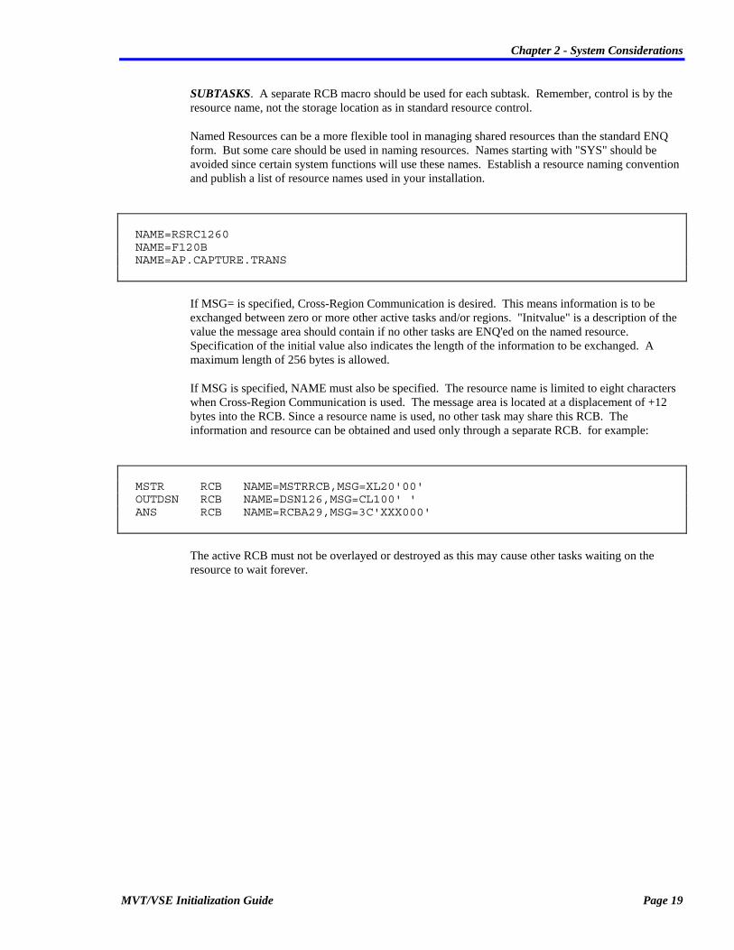
Named Resources can be a more flexible tool in managing shared resources than the standard ENQ form. But some care should be used in naming resources. Names starting with "SYS" should be avoided since certain system functions will use these names. Establish a resource naming convention and publish a list of resource names used in your installation.
NAME=RSRC1260 NAME=F120B NAME=AP.CAPTURE.TRANS
If MSG= is specified, Cross-Region Communication is desired. This means information is to be exchanged between zero or more other active tasks and/or regions. "Initvalue" is a description of the value the message area should contain if no other tasks are ENQ'ed on the named resource. Specification of the initial value also indicates the length of the information to be exchanged. A maximum length of 256 bytes is allowed.
If MSG is specified, NAME must also be specified. The resource name is limited to eight characters when Cross-Region Communication is used. The message area is located at a displacement of +12 bytes into the RCB. Since a resource name is used, no other task may share this RCB. The information and resource can be obtained and used only through a separate RCB. for example:
MSTR RCB NAME=MSTRRCB,MSG=XL20'00' OUTDSN RCB NAME=DSN126,MSG=CL100' ' ANS RCB NAME=RCBA29,MSG=3C'XXX000'
The active RCB must not be overlayed or destroyed as this may cause other tasks waiting on the resource to wait forever.
MVT/VSE Initialization Guide Page 19

Chapter 2 - System Considerations
ENQ
Control of a resource is achieved through the use of the ENQ macro. For example:
Label ENQ rcbname,WAIT=YES/NO
When WAIT=YES is specified, this macro does not differ from the standard IBM form of the macro. "rcbname" is the name of the label on the RCB macro. The name may optionally be specified in register notation with register zero preferred. Do not confuse the "rcbname" with the resource name. The resource name is only specified in the RCB macro. The ENQ macro simply points to the proper RCB. The use of a named resource, therefore, is accomplished through the RCB macro, not the ENQ macro.
WAIT=YES (the default, if not specified) indicates that the task will wait until the resource is available before proceeding with the next instruction. When control is finally given to the task following the ENQ, the resource is considered "owned" exclusively by the task. The resource may then be referenced freely and altered as needed without another task using the resource at the same time. Resource ENQ obviously implies that all tasks desiring to use a resource which might be shared, will ENQ on that resource in an identical fashion.
When Cross-Region Communication is used, the MSG area will appear to be common to all the tasks participating. When the ENQ is completed, the MSG area is updated to reflect the current common contents of this area. The MSG area should never be referenced or altered unless ENQ'ed by that task. If no other task has ever ENQ'ed on the resource name prior to the ENQ, the MSG area will contain the constant described in the MSG=operand of the RCB macro. The constant should be established so that a task can determine if it is the first to use the resource. Refer to the examples below.
When WAIT=NO is specified on the ENQ macro, this indicates that the task is requesting the resource but does not wish to wait if the resource is not available. Instead, an ECB will be posted when the task should again try to obtain the resource. This technique is very useful in programs using a WAITM (Wait Multiple) and have other functions to perform while waiting for the resource. These programs are generally on-line systems.
When WAIT=NO is specified, it is necessary to determine if the resource was actually ENQ'ed. If the resource ENQ is completed, register one will be set to zero. If the resource is busy, register one will contain the address of the RCB. The RCB may be used as an ECB for purposes of waiting. When the RCB is posted, the ENQ may be retried, but with no guarantee that it will actually obtain control of the resource.
Page 20 MVT/VSE Initialization Guide

Chapter 2 - System Considerations
DEQ
To release a resource, the DEQ or ENQRELSE macros should be used. If the resource is not released, it will be released automatically at task termination time. The ENQRELSE macro is only used with named RCB's as discussed below. For standard RCB's use the DEQ macro use is:
label DEQ rcbname
This macro is unaltered from DOS/VSE and DOS/VS. The resource is released for use by other tasks waiting or desiring the resource. "Rcbname" is the name of the RCB macro controlling the resource. The DEQ macro must not be used on Cross-Region Communication resources (RCB's with MSG=) unless the resource will not be used again by the task.
ENQRELSE
A new macro is used to provide a partial DEQ function primarily for tasks using the MSG form of RCB. The ENQRELSE macro is coded and used in a fashion identical to the DEQ macro except that the resource is not completely released. Whenever another task updates its MSG area through the use of the ENQ facility, the message area (if any) for the partially DEQ'ed resource is also updated. This technique prevents tasks from continually encountering the condition of appearing to be the first task to ENQ on the resource.
Normal named RCB's may also use ENQRELSE. The only motive for such use is to determine when an ENQRELSE or DEQ is performed by another task on the named resource. Both ENQRELSE and DEQ post the corresponding RCB's for all other tasks with an outstanding ENQ or which have partially released the resource with ENQRELSE. Named RCB's without the MSG= operand will normally use the DEQ macro instead of ENQRELSE.
MVT/VSE Initialization Guide Page 21

Chapter 2 - System Considerations
Posting ECB's For Another Region
An important aspect of communicating between regions is the ability to determine when another region has completed some unit of work. While no specific resource is involved, the ENQ facility can provide a technique for posting an ECB in another region.
A named RCB may be treated as an ECB for purposes of waiting for an event. The RCB will be posted each time another task issues a DEQ or ENQRELSE for the named resource. This posting is normally an indication that the resource is available for ENQ, but the ENQ is not required. To wait for another posting, unpost the RCB directly (NI RCB+2,X'FF'-X'80') or issue an ENQ followed by an ENQRELSE.
A prerequisite for waiting on an RCB posting is to issue an initial ENQ for the named resource. Control of the resource is not required, only the initial issuance of the macro. If control is obtained, remember to issue an ENQRELSE to allow another task to ENQ. Both the unsuccessful ENQ and the ENQRELSE unpost the RCB to allow it to immediately be used in a wait list. Do not use the DEQ macro if you expect an RCB to be posted by another task.
One technique for waiting for a multiple number of events to be posted by other tasks or regions is to use flag bytes within a MSG area. Each time an event is posted, a counter in the MSG area is incremented and an indicator is set to indicate the job completed. Example #6 illustrates this use.
Standard ENQ
ENQ RCB1 Get control of resource * ** Task will wait until resource control * ** is obtained. Resource may be used at * ** this point. ... DEQ RCB1 Release resource ... RCB1 RCB , Standard RCB format
Page 22 MVT/VSE Initialization Guide

Chapter 2 - System Considerations
Named ENQ
ENQ RCB2,WAIT=YES Get control of named resource * ** Task will wait until resource control is * ** obtained resource may be used at this point ... DEQ RCB2 Release resource ... RCB2 RCB NAME=DBC100BU Named resource * * This RCB cannot be used by another subtask RCB3 RCB NAME=DBC100BU Named resource * ** A 2nd subtask would use this RCB
ENQ Without A Wait
ENQ100 ENQ RCB4,WAIT=NO Ck if resource available LTR R1,R1 ck if resource enq'ed BZ ENQ120 YES - use resource ST R1,WAIT8 Put ECB addr in wait list ... WAITM WLIST Wait for an event ... * ** If RCB4 was posted, branch to ENQ100 * ** to return enq ... RCB4 RCB NAME=ABC.123456.FGHJIK.ZYXUV Named resource * ** with an extended name. WLIST DC A(ECB1) ECB list for WAITM ... WAIT8 DC A(RCB4) Wait for ability to obtain * ** resource DC X'FF' End of list * ** A simple wait could have been used after the ENQ * ** instead of a WAITM. Be sure to wait only if the * ** resource has NOT been obtained. ENQ120 LTR R1,R1 ck if resource enq'ed BZ ENQ130 YES WAIT (1) Wait for retry of ENQ B ENQ100 Retry ENQ ENQ130 ...
MVT/VSE Initialization Guide Page 23
Chapter 2 - System Considerations
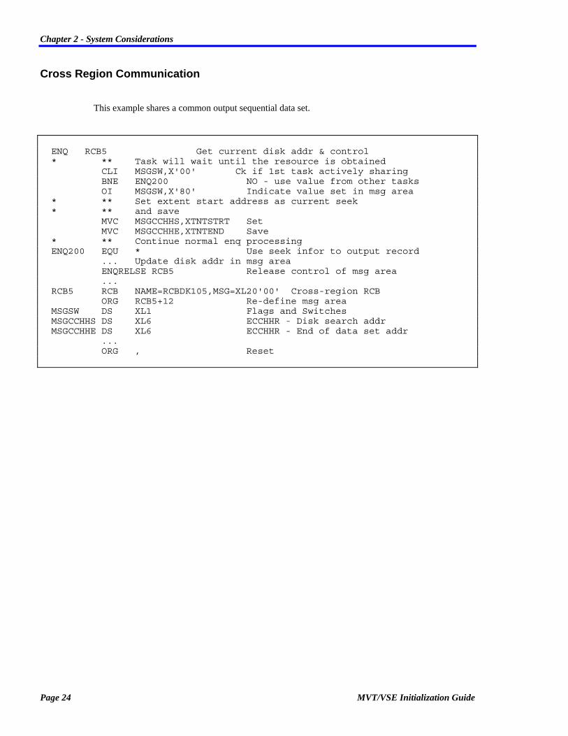
Cross Region Communication
This example shares a common output sequential data set.
ENQ RCB5 Get current disk addr & control * ** Task will wait until the resource is obtained CLI MSGSW,X'00' Ck if 1st task actively sharing BNE ENQ200 NO - use value from other tasks OI MSGSW,X'80' Indicate value set in msg area * ** Set extent start address as current seek * ** and save MVC MSGCCHHS,XTNTSTRT Set MVC MSGCCHHE,XTNTEND Save * ** Continue normal enq processing ENQ200 EQU * Use seek infor to output record ... Update disk addr in msg area ENQRELSE RCB5 Release control of msg area ... RCB5 RCB NAME=RCBDK105,MSG=XL20'00' Cross-region RCB ORG RCB5+12 Re-define msg area MSGSW DS XL1 Flags and Switches MSGCCHHS DS XL6 ECCHHR - Disk search addr MSGCCHHE DS XL6 ECCHHR - End of data set addr ... ORG , Reset
Page 24 MVT/VSE Initialization Guide

Chapter 2 - System Considerations
Cross Region Communication
In this example an on-line system submits jobs to the reader queues to run in batch mode. The batch mode jobs must transmit an answer to the on-line system so it may relay it to a terminal. The on-line system issues an ENQ for the Cross-Region RCB when it is activated and verifies that it is first to issue the ENQ. The following code is placed in the application routine to communicate with the on-line region.
ENQ RCB6,WAIT=YES Get control of the resource CLI XCHSW,X'00' CK if on-line active yet BE ERROR NO - error MVC XCHANS,ANSWER Put answer in msg area ENQRELSE RCB6 Release msg area ... RCB6 RCB NAME=ANSCTL10,MSG=XL10'00' Cross regn RCB ORG RCB6+12 Redefine msg area XCHSW DS XL1 Flags and switches DS XL1 Filler XCHANS DS XL8 Answer area ORG , Reset
The actual on-line program's code might be as follows:
* *** INITIALIZATION ROUTINE *** ENQ ANSRCB,WAIT=YES Get control of resource and * ** insure part of cross-region resource list. MVI XCHSW,X'FF' Indicate on-line system active ENQRELSE ANSRCB Release control of resource * ** The RCB has been unposted at this point to * ** allow a wait on the RCB as an ECB. ... WAIT WAITM WAITLIST Wait for an event ... * ** Process posting of ANSRCB. ANSRCB is posted * ** when the answer has been placed in the msg * ** area. ENQ ANSRCB,WAIT=NO Try to get resource LTR R1,R1 CK if resource obtained BNZ WAIT NO - wait for another posting * ** Use answer in XCHANS. ... ENQRELSE ANSRCB Release control of resource ... ANSRCB RCB NAME=ANSCTL10,MSG=XL10'00' Cross region RCB ORG ANSRCB+12 Redefine msg area XCHSW DS XL1 Flags and switches DS XL1 Filler XCHANS DS XL8 Answer area ORG , Reset
MVT/VSE Initialization Guide Page 25

Chapter 2 - System Considerations
Cross Region Communication
In this example a variable number of regions may wish to inform a master task that certain work has been completed. Each slave task sets a one byte indicator in the common MSG area to indicate the task completed. A subscript is maintained to indicate the number of jobs completed. The code for a slave task might be as follows:
ENQ MSTRRCB Get control of master msg area * ** Task will wait until resource is available. SR R2,R2 Prepare for IC IC R2,SUBSCRPT Get current subscript value LA R3,JOBCODES(R2) Addr for job code MVI 0(R3),C'K' Put job code in table LA R2,1(R2) Increment subscript STC R2,SUBSCRPT Save new event count ENQRELSE MSTRRCB Release control of msg area ... MSTRRCB RCB NAME=MSTRCTL,MSG=XL100'00' Cross-region RCB ORG MSTRRCB+12 Redefine msg area SUBSCRPT DS XL1 Number of events completed JOBCODES DS 99CL1 Codes of jobs completed
Page 26 MVT/VSE Initialization Guide

Chapter 2 - System Considerations
The master task would want to wait for the posting of the RCB as in Example #5 above. Its code might appear as follows:
* ***INITIALIZATION ROUTINE *** ENQ CTLRCB,WAIT=NO Put entry in resource list LTR R1,R1 CK if resource control obtained BNZ INIT150 NO - not needed now ENQRELSE CTLRCB Release since only an entry was * ** needed in resource table, not actual control. INIT150 EQU * ... WAITM WAITM WAITLIST Wait for an event ... * ** Process posting of CTLRCB. ENQ CTLRCB,WAIT=NO Try to get control of msg area LTR R1,R1 CK if resource obtained BNZ WAITM NO - continue waiting * ** USE SUBSCRIPT TO CK JOB CODES. Save conds in * ** an alternate area to minimize enq time. * ** Reset msg area to HEX zeroes. ENQRELSE CTLRCB Release control of msg area * ** The ENQRELSE automatically unposts the RCB to * ** allow a new wait. ... CTLRCB RCB NAME=MSTRCTL,MSG=XL100'00' Cross-region RCB ORG CTLRCB+12 Redefine msg area SUBSCRPT DS XL1 Number of events completed JOBCODES DS 99XL1 Codes for jobs completed ORG , Reset WAITLIST DC A(CTLRCB) ECB addr ... DC X'FF' End of wait list
MVT/VSE Initialization Guide Page 27


Chapter 3 - Installation
Chapter 3 Installation
This chapter is concerned with installation of MVT/VSE and the required planning which must be done prior to the actual installation of the operating system.
Two options are available for the installation of MVT/VSE. These are:
• Self installation: you perform the actual installation of MVT/VSE from the installation tape(s).
• SPI installation: SPI Field Service personnel will perform the installation.
The method you select should be discussed with your salesperson and the Field Support staff. If you should elect to install MVT/VSE yourself, you will receive all installation tape(s). The installation tape will install the base MVT/VSE system (including SPRI and PLF).
You may also receive an SPI Product tape. This tape is used to update: • The base MVT/VSE operating system • SPRI • PLF • SPI Expiration System
to the latest service (PTF) levels. Complete installation instructions for installing the Product tape will be included.
MVT/VSE Initialization Guide Page 29

Chapter 3 - Installation
Planning For Installation This section is devoted to the planning that will be required prior to the actual installation of the MVT/VSE system.
Installation Timetable
The specific installation schedule will vary for each customer, but certain events occur as part of every installation. A preinstallation package is sent out in advance of the arrival of the SPI Field Support Representative. This package allows the user to convert all JCL and libraries in advance, hence resolving all questions regarding Form Names, regions, JCL and procedure usage.
The first few days after the FSR arrives consists of final planning, restoration of the MVT/VSE distribution system, nucleus assembly, demonstrations, and operator training. The next stage is to convert any remaining libraries and JCL and to create system data sets such as the SPOOL queues. This takes another two days. The system is then in production, but the FSR remains to finish tuning the system and to answer questions. This period usually lasts three days. After the FSR leaves the site, questions and problems will be handled by the Technical Support Staff of Software Pursuits.
Software Compatibility
Software Pursuits works very closely with all reputable vendors to insure compatibility of software products with MVT/VSE. While compatibility may require the cooperation of some vendors, Software Pursuits makes every effort to help these vendors to remain compatible with MVT/VSE and to take advantage of its unique features.
In preparation for an installation, a survey must be made of all system software in use at the site. While there are very few products which will not run under MVT/VSE, any alteration of any system component should be checked. MVT/VSE incorporates all of IBM's features for DOS/VSE Advanced Functions (Release 3) and BTAM-ES. Most of the products which will run under DOS/MVT will run under MVT/VSE.
The following products are known to require VSE versions in order to run under MVT/VSE. Please talk with your Sales Representative or SPI Technical Support for additional information. Of particular note are the following products:
ACF/VTAM CA-DYNAM/D/T/FI CA-SORT CICS/VSE CONMAN DCRABS DITTO DOCS EASYTRIEVE EPAT EPIC IOSYS OWL QUOTA SYNCSORT SYSTEM MANAGER VOLLIE VSE/VSAM WESTI WESTI-SCEPTER
Page 30 MVT/VSE Initialization Guide

Chapter 3 - Installation
Features unique to MVT/VSE 1. Both single and dual address MICR devices may be used at the same time. 2. Multi-path Channel Scheduling. 3. Improved Page Management. 4. 15 Batch Regions. 5. Multiple Logical Transient Areas (LTA's). 6. Channel Scheduling. 7. Seek Separation for 2311 and 2314 disks (no longer available in IBM's DOS/VSE). 8. Extended Job Accounting Data Collection. 9. Nucleus is built during IPL; user assembles static default gen options in an nucleus
"OPTION" phase. 10. SPRI Spooling System. 11. Extended Procedure Language.
Unsupported Features 1. 125D Console CRT Screen. 2. 115/125 Line Mode Tables. 3. QTAM 4. Tape Cartridge Reader Support. 5. Data Cell Support.
Virtual Machine Support
This section is designed as a aid for those installations that will be using MVT/VSE under the VM Operating Systems (VM/SP, VM-HPO and VM/XA). It is not designed as a definitive discussion of all the different operations available under VM. However, it should provide the "first time" VM user with some insights and provide aid during the installation and use of MVT/VSE under VM.
Prior to the actual installation of MVT/VSE under VM, the person responsible for the effort should read and have a good understanding of the IBM publication GC19-6212: Virtual Machine/Running Guest Operating Systems. This publication describes and discusses several considerations when operating "guest" operating systems under VM. Although the publication does not specifically address MVT/VSE, all of the information given on VSE guests will apply to MVT/VSE also.
The use of the VM operating system provides the user with the ability to operate multiple MVT/VSE "guest" systems on a single CPU. This provides several cost and operational benefits. However, the use of VM requires that the installation consider the overall affect of VM on the MVT/VSE system and the actual installation needs.
The VM operating system is designed to provide the user with the ability to perform several operational tasks at one time. VM provides support for the guest operating systems and its own interactive services (mainly CMS). This allows its use to accomplish several different types of processing on a single CPU with a minimum of interruption to all other VM guests and CMS users.
MVT/VSE Initialization Guide Page 31

Chapter 3 - Installation
VM consists of two main components, these are:
CP The Control Program. This is the component of the VM system that actually controls the system hardware and provides a suitable environment for the "guest" systems.
CMS The Conversational Monitoring System. This component of VM is designed as a user interactive system for performing specified computing tasks.
The ability of the CP component to build and provide an environment that simulates a real CPU, enables MVT/VSE to operate. To CP, MVT/VSE is a "guest" operating system that is presented with CP services that are "virtually" the same as if MVT/VSE were operating on a real CPU.
MVT/VSE And VM Handshaking
The MVT/VSE system is designed to "know" when it is operating as a guest under VM. This allows MVT/VSE to let VM perform several tasks that MVT/VSE itself would normally perform. Among these are:
1. Page fault handling that allows MVT/VSE to suspend the causing task and dispatch another task.
2. Support for the VM/SNA Console Communications Services (SNA CCS) through the use of the VM/VTAM Communications Network Application (VM/VCNA). This support is provided through the use of the VM Inter-User Communications Vehicle (IUCV).
3. Bypassing of the VM testing of modified BTAM Autopoll CCW test. This is done by issuing the "SET~AUTOPOLL~ON" command and allowing BTAM to issue a DIAGNOSE to VM when the Autopoll CCW sting has been modified.
VM Considerations
Performance
When a VM system is installed, the first expection is one of being able to accomplish several tasks at the same time. However, most first time users of VM are not ready for the increased load placed on the system by VM. In some instances, this increased load will result in an actual reduction in throughput. This is generally noticeable on small (4331, 4341) systems. These systems do not provide sufficient "horsepower" to support VM and several additional "guest" MVT/VSE systems. This is particularly true when the MVT/VSE guest is being used in support of a large network.
Page 32 MVT/VSE Initialization Guide

Chapter 3 - Installation
Users of large CPUs will not notice any change (or very little change) in their normal operations. This is true even when supporting large networks. Regardless of the CPU size, the user should be aware that many factors interact that will affect overall performance. Among these are:
1. The availability of Virtual Machine Assist (VMA) and VM Extended Control-Program Support (ECPS) microcode features. It is necessary that these features be available on your CPU if you are running MVT/VSE under VM. These features provide needed enhancements that will enable the MVT/VSE system to operate efficiently and properly. If these features are not available on your CPU, you should contact your vendor and have them installed prior to any installation of VM. It should be noted that some hardware vendors DO NOT supply or support these features on some CPUs. The absence of this support may or may not affect your operations. Your hardware vendor is best able to determine the exact needs of your installation and should be consulted on the overall effects to your environment.
2. Paging activity. MVT/VSE will allow the VM system to provide all paging activity. This reduces the need for "double" paging. This is when VM and the guest system both attempt paging. By allowing VM to provide all paging, MVT/VSE is able to operate more efficiently and reduces the amount of CPU cycles needed for the paging activity.
3. The number of real interruptions will also have a direct affect on the performance of MVT/VSE under VM. Because VM actually handles all interrupts, there is increased overhead when a guest system has a large amount of I/O. Again, this is most noticeable when you are using large online systems.
4. The number of guest machines operating under VM will also have a direct affect on your overall performance. An installation using two guests will not experience the same degradation as an installation using 4 or more guests. As less guests are executing, VM will spend more time servicing the same guest. As the number of guests increases, VM must allocate more time to servicing more virtual machines.
Additional performance factors are discussed in the IBM publication GC19-6212: VM/Running Guest Operating Systems.
Online Vs. Batch Guest Machines
Each installation must consider the nature of their MVT/VSE guest system operations. This involves the assignment of priorities to "batch" and "online" guests.
As a general rule, most installations give highest priority to online systems (CICS, etc.). If you will be operating a single guest MVT/VSE, you should throughly understand MVT/VSE operations and options that insure an online system receives the highest throughput. If you will be using separate guest machines for online and batch, you should consider the VM options that provide highest priority to the guest that must have the best throughput.
In all cases, the actual speed of the CPU and the availability and placement of DASD devices on channels, should be considered. In some instances, you may wish to reconfigure your DASD to take best advantage of VM channel I/O. This also involves the consideration of "minidisks" vs. "dedicated" devices and channels.
MVT/VSE Initialization Guide Page 33

Chapter 3 - Installation
Setting VM Guest Performance Options
The VM system provides several commands that allow the installation to give a guest "preferred" status. Among these are:
1. Favored Execution (SET FAVORED command)
2. Locked Pages (LOCK command)
3. Reserved Pages (SET RESERVED command)
4. Priority (SET PRIORITY command)
5. VM Queue Control (SET QDROP command)
Each of these commands is documented in the VM CP Command Reference.
Each command has a slightly different affect on the guest systems. The use of one command may provide excellent results for one guest, but fail to produce the desired results for another guest. The installation should review each command and decide which commands may be appropriate for which guest.
As a general rule, it always a good idea to use the "LOCK" command for each guest to lock page zero (LOCK userid 0 0) in core. This will insure that page zero is never paged out and will always be available during operations. Page zero is the same as a native MVT/VSE systems low storage locations. This page contains information that is constantly updated and referenced (PSWs, etc). It is particularly important to understand that there is a difference in the operation of VM/SP, VM-HPO and VM/XA. Each of these VM systems was designed with specific CPU support. Each of these VM system is designed with specific scheduling and I/O handling. As a result, a option that may provide acceptable performance under VM/SP may not be appropriate under VM-HPO. In all instances, you should become throughly familiar with the different performance options and their effects on your VM system.
The MVT/VSE Nucleus Under VM
Installations using MVT/VSE under VM need not make any special considerations. The MVT/VSE nucleus may be generated with normal macros.
Device Support Under VM
All of the devices currently supported by MVT/VSE are available under the VM operating system. In most instances, a device that is supported by MVT/VSE and not supported by VM, can be defined to the VM system with a dummy device type and dedicated or attached to the MVT/VSE system. This technique does not adversely affect the MVT/VSE or VM systems. Devices that are supported by VM and not supported by MVT/VSE, can generally be used by MVT/VSE. In some instances, this will require that the device be defined in a special manner to MVT/VSE. Contact the SPI Technical Support group or discuss these special devices with your installer.
Page 34 MVT/VSE Initialization Guide

Chapter 3 - Installation
SPOOL Use Under VM
Both MVT/VSE and VM provide SPOOL services. In almost all cases, the MVT/VSE SPRI SPOOL areas should be used for normal MVT/VSE processing. This is particularly true when multiple MVT/VSE guests are sharing the same SPRI queues.
Since you will normally have your MVT/VSE system handling the normal unit record devices (Printer/Reader/Punch), it is much more efficient to have SPRI control the devices directly. This will eliminate the need to SPOOL data to SPRI and then have the data re-SPOOLed to VM (double SPOOLing).
If it necessary to process VM SPOOL data, you may detach the needed device from the MVT/VSE virtual machine and use it under the VM system. This is done as follows:
1. On the MVT/VSE guest Detach the needed device (CP DETACH cuu). Be sure the device is inactive. If SPRI should attempt to use the device for processing, VM will present a "NOT READY" condition (the same as pressing STOP). When the device is re-attached to the MVT/VSE guest, a "READY" condition is presented and processing continues normally.
2. On the VM system 1. Vary the needed device online (VARY cuu ONLINE). 2. Start the device (START cuu CLASS ....). 3. When your VM files are complete, drain the device ((DRAIN cuu). 4. Re-attach the device to the MVT/VSE system (ATTACH cuu userid or ATTACH cuu userid
vcuu).
In some instances, you may wish to send files back and forth between VM and the MVT/VSE guests. Using the VM directory "SPOOL" statement, you are able to define "virtual" devices that will be treated as "real" devices by the MVT/VSE guest machine. These devices can then be used to send files to and receive files from VM. Note that these "virtual" devices must be known to MVT/VSE (ADD Statement) and SPRI to operate properly. Refer to the current MVT/VSE and SPRI documentation for additional information on the use of these types of devices.
MVT/VSE Initialization Guide Page 35

Chapter 3 - Installation
The VM Directory
The generation of VM guest machines is controlled with the use of the VM directory. This file contains statements that allow CP to generate the desired "virtual" configuration for the guest system.
The following example shows two MVT/VSE guest systems.
USER MVT1 MVT 16M 16M BEG 50 OPTION ECMODE BMX REALTIMER CPUID 000003 ACCOUNT 999999999 MVT1 IPL CMS PARM AUTOCR CONSOLE 009 3215 T OPERATOR SPOOL 00C 3505 * SPOOL 00D 3525 * SPECIAL 080 3270 SPECIAL 081 3270 SPECIAL 082 3270 SPECIAL 083 3270 DEDICATE 01F 01F DEDICATE 00E 00E DEDICATE 134 134 LINK MAINT 190 190 RR LINK MAINT 19E 19E RR MDISK 130 3350 000 555 MVTRES MWV RMVT WMVT MMVT MDISK 131 3350 000 555 LIBR01 MWV RMVT WMVT MMVT MDISK 132 3350 000 555 WORK01 MWV RMVT WMVT MMVT MDISK 133 3350 000 555 WORK02 MWV RMVT WMVT MMVT USER MVT2 MVT 16M 16M BEG 64 OPTION ECMODE BMX REALTIMER CPUID 000004 ACCOUNT 999999999 MVT2 IPL CMS PARM AUTOCR CONSOLE 01F 3270 T OPERATOR SPOOL 00C 3505 * SPOOL 00D 3525 * SPECIAL 080 3270 SPECIAL 081 3270 SPECIAL 082 3270 SPECIAL 083 3270 DEDICATE 01E 01E LINK MAINT 190 190 RR LINK MAINT 19E 19E RR LINK MVT1 130 130 MW LINK MVT1 131 130 MW LINK MVT1 132 130 MW LINK MVT1 133 130 MW
USER Statement
1. Two MVT/VSE guest machines are allowed access to the VM system. The user identifications (userid) are: MVT1 and MVT2.
Page 36 MVT/VSE Initialization Guide

Chapter 3 - Installation
2. Both guests are assigned VM authorization classes:
B This class allows the MVT/VSE guests to attach and detach any needed system resources.
E This authorization class is required to allow MVT/VSE, and other SPI products, proper access to system information for the SPI expiration system. You may also use authorization class "C" in place of "E". however, one or the other MUST be specified.
G This is the general user class. This class prevents the guest from interfering with the operations of other guests.
3. The priorities (50 and 64) of the guests are defined to prevent problems with servicing from VM. The priority of 50 is a higher priority than 64 (0 is the highest priority and 100 is the lowest priority).
OPTION Statement
This statement provides virtual machine options that are required for efficient operations. These are:
BMX Allows VM to overlap multiple SIO(F) requests on a channel.
REALTIMER Causes the virtual interval timer to be updated during virtual wait state.
ECMODE Provides Extended Control functions (Dynamic Address Translation and register use).
CPUID Provides a specified CPUID for each guest system. This is normally used when you are operating two or more MVT/VSE guests.
IPL Statement
The IPL statement is used to indicate that a saved system name (CMS) or device address should be utomatically IPLed. The statements in the example show the IPL of the CMS system. This is used to allow the "PROFILE EXEC" to be automatically invoked. This EXEC can then be used to complete the setup of the guest MVT/VSE system.
The directory "LINK" statement is used for links to the 190, 19E and 19D minidisks of the MAINT userid. The 190 minidisk contains the data necessary for the IPL of the CMS system. If this LINK is not provided, the IPL of CMS cannot be done.
CONSOLE Statement
This statement provides a virtual console address for the guest machine. Note that the different MVT/VSE systems have different addresses defined for their consoles.
Because these two MVT/VSE systems are sharing the same SYSRES device, and the MVT/VSE nucleus is designed to recognize the Operator Console at address "01F", it is necessary to provide this address for IPL. However, "MVT1" has the real "01F" dedicated. This presents a problem when the "MVT2" system is IPLed. It will look for the address "01F" and attempt to use that as the Operator Console. Using the "CONSOLE" statement, we are able to indicate to "MVT2" that any console that is first used for logon will have a virtual address of "01F". When the "MVT2" system is IPLed, it will automatically use that logon terminal as the Operator Console. All IPL messages will be directed to that console. If this were not done, the first terminal device that happened to be connected (via the DIAL command, the ATTACH command or a directory DEDICATE statement) to the "MVT2" guest
MVT/VSE Initialization Guide Page 37
Chapter 3 - Installation
that presented an interrupt (hitting the ENTER, ATTN or PA1 keys) would cause the system to use that terminal as the Operator Console. This would direct all IPL messages to that terminal.
The problem of an Operator Console for the second guest could also be alleviated with the ATTACH command or the directory DEDICATE statement.
This would be done as follows:
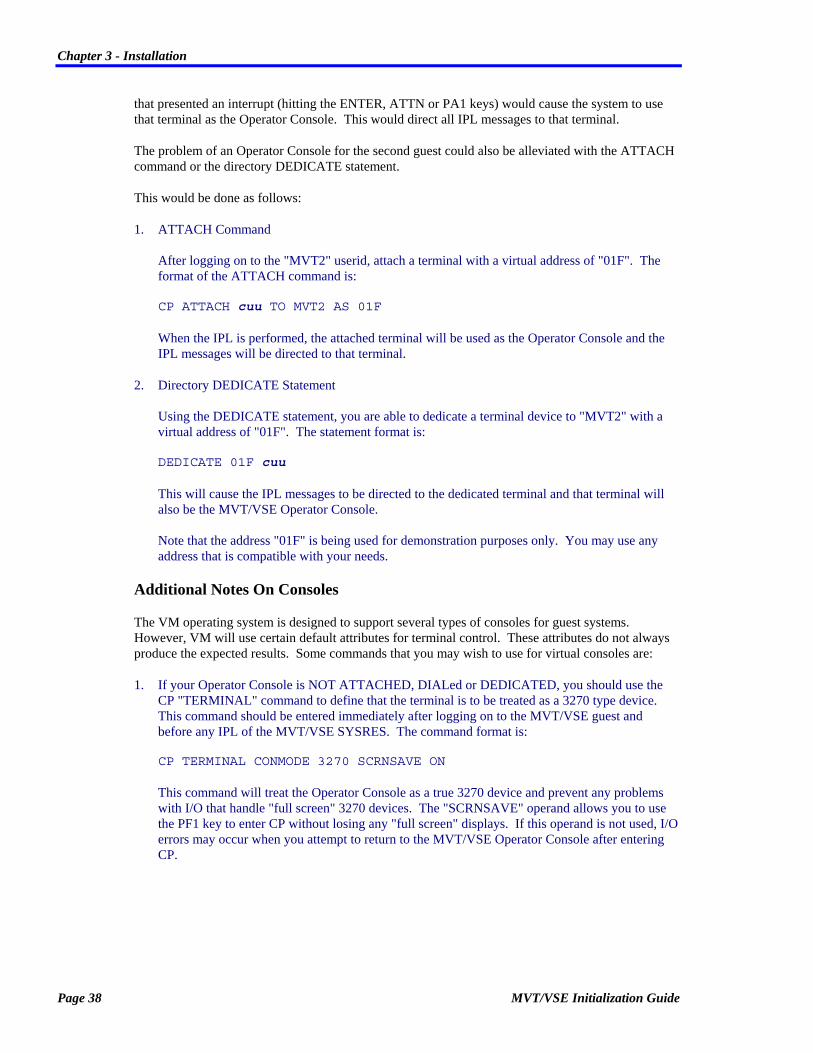
1. ATTACH Command After logging on to the "MVT2" userid, attach a terminal with a virtual address of "01F". The format of the ATTACH command is: CP ATTACH cuu TO MVT2 AS 01F When the IPL is performed, the attached terminal will be used as the Operator Console and the IPL messages will be directed to that terminal.
2. Directory DEDICATE Statement Using the DEDICATE statement, you are able to dedicate a terminal device to "MVT2" with a virtual address of "01F". The statement format is: DEDICATE 01F cuu This will cause the IPL messages to be directed to the dedicated terminal and that terminal will also be the MVT/VSE Operator Console. Note that the address "01F" is being used for demonstration purposes only. You may use any address that is compatible with your needs.
Additional Notes On Consoles
The VM operating system is designed to support several types of consoles for guest systems. However, VM will use certain default attributes for terminal control. These attributes do not always produce the expected results. Some commands that you may wish to use for virtual consoles are:
1. If your Operator Console is NOT ATTACHED, DIALed or DEDICATED, you should use the CP "TERMINAL" command to define that the terminal is to be treated as a 3270 type device. This command should be entered immediately after logging on to the MVT/VSE guest and before any IPL of the MVT/VSE SYSRES. The command format is: CP TERMINAL CONMODE 3270 SCRNSAVE ON This command will treat the Operator Console as a true 3270 device and prevent any problems with I/O that handle "full screen" 3270 devices. The "SCRNSAVE" operand allows you to use the PF1 key to enter CP without losing any "full screen" displays. If this operand is not used, I/O errors may occur when you attempt to return to the MVT/VSE Operator Console after entering CP.
Page 38 MVT/VSE Initialization Guide

Chapter 3 - Installation
It is generally a good practice to use this command in the "PROFILE EXEC" of the guest machine. It should however, be the last command in the EXEC. The command causes CP to be entered so that processing of the EXEC is terminated. Issuing this command prefixed with a pound sign (#) will not cause the entry into CP.
2. Combining SPECIAL and DEDICATED Console Devices The VM directory allows you to combine SPECIAL (virtual consoles that may be used for DIAL purposes) and DEDICATEd (devices that are only used by one userid) devices. under normal circumstances, this is not a problem. However, VM does not allow for devices that require "unshared" UCWs to be combined on the same virtual control unit, with devices that use "shared" UCWs. This problem can be overcome with the use of the "DEFINE" command. Instead of mixing SPECIAL and DEDICATE statements in the VM directory, you should use the DEDICATE statement only. Devices that would be defined with the SPECIAL statement should not be defined in the VM directory, but rather from the userid using the DEFINE statement. This might be done as follows:
VM Directory Statements (These devices are all defined as having "unshared" UCWs) DEDICATE 0A0 0A0 DEDICATE 0A1 0A1 DEDICATE 0A2 0A2 DEDICATE 0A6 0A6 DEDICATE 0A7 0A7 DEDICATE 0A8 0A8 ... CP DEFINE Statements CP DEFINE 0A3 3270 CP DEFINE 0A4 3270 CP DEFINE 0A5 3270 ...
The DEFINE Statements may be issued from the terminal or from an EXEC procedure (generally the "PROFILE EXEC"). This will generate the virtual devices 0A3, 0A4 and 0A5 the same as a SPECIAL statement except that they will take on the attributes of the DEDICATEd devices Virtual Control Unit (VCU).
SPOOL Statement
The VM directory SPOOL statement is used to define virtual SPOOL devices that will be used by the guest system.
If you are planning to transfer files between CMS users and the MVT/VSE system, you should have SPOOL statements for a virtual reader and punch. These devices will allow files to be transferred between VM SPOOL and SPRI. The addresses used for the virtual devices is up to the installation. You must remember that the virtual devices generated by the SPOOL statement must also be defined to MVT/VSE (IPL ADD statement) and to SPRI (READER, PUNCH, LOCATION, etc. statements).
MVT/VSE Initialization Guide Page 39

Chapter 3 - Installation
This insures that the virtual devices are treated properly by MVT/VSE, SPRI and VM when files are transferred.
You may also define virtual printers using the SPOOL statement. In some instances, you may wish to define a printer to MVT/VSE and SPRI that will be used for transferring print to VM SPOOL. By defining a virtual printer and then defining it to MVT/VSE and SPRI, you are able to direct SPRI output to that printer and it will be placed into the VM SPOOL area. Most installations use this type of transfer when they have several printers and at least one is always available to the VM system. Using a special output Route Code for this type of printer will help with the handling of report distribution to VM.
SPECIAL Statement
The SPECIAL statement is used to define certain virtual devices for the guest system that VM is to treat in a special manner.
In the case of a terminal, a SPECIAL statement allows you to use the CP "DIAL" command to access the guest system. This is very useful for installations that have a limited number of terminals and must access two or more MVT/VSE guests. Using the "DIAL" command you are able to indicate the guest to which you wish to connect. For example:
CP DIAL MVT1 0A3
or
CP DIAL MVT2 0A3
The VM message:
DIALED TO userid cuu
Indicates that the DIAL operation was successful.
Once you are connected to the guest system, the terminal will be treated as a normal terminal. If the terminal was designated as a VTAM terminal, then VTAM will receive control.
When you are done with your operations on one guest, you must indicate that the terminal is to be droped from that guest and returned to VM so that you may DIAL to the other guest. This is done with the use of the CP "RESET" command. The command should be issued by the Console Operator. The command format is:
CP RESET cuu
This will cause the terminal to be reset and droped from the guest system. The terminal will then be returned to VM and the message:
DROP FROM userid cuu
will be displayed on the terminal. You are then free to DIAL to another guest or logon to a VM userid.
You may also define virtual Channel-To-Channel Adapters with the SPECIAL statement. Installations wishing to use CTCAs should research the SPECIAL statement and decide if this type of statement may be of use.
Page 40 MVT/VSE Initialization Guide

Chapter 3 - Installation
DEDICATE Statement
The DEDICATE statement is used to dedicate a given device to a guest system only. A device may only be dedicated to a single userid at a time. Use of the DEDICATE statement for DASD and TAPE devices is not recommended in installations where the devices will be shared.
As a general rule, you should dedicate only those devices that will be used exclusively by one guest system. This is generally terminals, printers, punches and readers.
If a terminal is to be dedicated to a guest system, you must insure that the terminal is not enabled for for VM access (If there is a VM logo screen on the terminal, it cannot be dedicated to a guest system). To insure that the terminals are properly disabled before the MVT/VSE guest is logged on, you may have an EXEC on the OPERATOR user that issues the CP "DISABLE" command for the terminals needed. Another method is to not issued the CP "ENABLE" command for any terminals before the guest system(s) are logged on the system.
Any VM device that is currently in use by any other userid, will not be dedicated when the guest system is logged on (refer to the MDISK and LINK statements for DASD device sharing).
MDISK Statement
The VM directory MDISK statement is used to define a virtual "disk" that is assigned to a userid. You may use the MDISK statement to assign a portion of a DASD device or an entire DASD device to a guest.
If you will be sharing DASD devices between two or more guest systems, only one of the users should have the minidisk defined with the "MDISK" statement. Other guests should have "LINK" statements that provide access to the DASD device(s).
Note that the MDISK statement for the "MVT1" guest uses the characters "MWV" in all of the "MDISK" statements. This is used to indicate the mode that the guest is to receive when the minidisk is assigned at logon time. "MW" indicates that the user will receive write access in all cases. The letter "V" is used to indicate that VM should provide virtual RESERVE/RELEASE support for the device.
The "LINK" statements use the mode letters "MW". This will also allow that user to gain write access in all instances. This is true even if the owning guest is not logged on the system. Because the "MDISK" statement for the owning user specifies "MWV", the second guest will automatically use the virtual RESERVE/RELEASE functions.
The combination of "MDISK" and "LINK" statements means that you may have several MVT/VSE guests sharing the same DASD devices at the same time. however, you must remember that this situation requires that you are using the MVT/VSE "LOCK FILE" (The MVT/VSE DLF statement) If the "LOCK FILE" support is not being used, there is no method of insuring the integrity of the shared DASD.
Refer to the proper VM documentation relating to the running of guest operating systems.
MVT/VSE Initialization Guide Page 41

Chapter 3 - Installation
LINK Statement
The LINK statement is used to indicate that VM should generate a virtual "link" to the minidisk device for the user indicated. This provides a method of allowing access to several users when only a single minidisk exists. Each user is allowed to use the indicated LINK device.
When you are sharing DASD devices between two or more MVT/VSE guests, you should use the LINK statement for proper access and control of those minidisks (See the MDISK statement below). Only one of the guests will "own" (via an MDISK statement) the actual minidisk. All other users will have access via the LINK statement.
Please note that there are several methods of providing links to minidisks. Refer to the LINK Statement in the VM documentation for a complete description of proper linking techniques.
Page 42 MVT/VSE Initialization Guide

Chapter 3 - Installation
An MVT/VSE Profile EXEC
The CMS "PROFILE EXEC" is automatically executed when the CMS system is IPLed. Using this EXEC procedure, you are able to define certain options that may be executed prior to the actual IPL of the MVT/VSE system.
A sample PROFILE EXEC is shown on the next page to provide an example of how you may wish to create your installation's PROFILE EXEC. This EXEC is written using the VM "REXX" procedure language.
Note that the EXEC is designed to provide a single PROFILE EXEC for two guest virtual machines.
/* -------------------------------------------------------- */ /* Sample PROFILE EXEC for a guest MVT/VSE virtual machine */ /* -------------------------------------------------------- */ /* Which MVT/VSE guest is this ? */ /* -------------------------------------------------------- */ Select When Userid() = 'MVT1' Then Signal MVT1 When Userid() = 'MVT2' Then Signal MVT2 Otherwise Do Say 'This is not a valid MVT/VSE userid - exiting.' Exit 9999 End End Exit MVT1: /* -------------------------------------------------------*/ /* This guest runs disconnected using the real 01F as the */ /* operator console */ /* -------------------------------------------------------*/ /* Be sure 01F is the console. */ /* -------------------------------------------------------*/ 'QUERY VIRT 01F ( STACK' Pull @graf rest If @graf ^= 'GRAF' Then Do 'CP MSG OP Device 01F not available - Logging off' 'CP LOGOFF' Exit End /* ----------------------------------------------*/ /* Define terminals to be used for DIAL purposes */ /* ----------------------------------------------*/ 'CP DEFINE 0A0 3270' 'CP DEFINE 0A1 3270' 'CP DEFINE 0A2 3270' 'CP DEFINE 0A3 3270' /* -------------------------------------------------------------*/ /* Be sure needed terminals are disabled and then attached */ /* -------------------------------------------------------------*/ 'CP DISABLE 038 039 03A 03B' 'CP ATTACH 038 TO MVT1' 'CP ATTACH 039 TO MVT1' 'CP ATTACH 03A TO MVT1' 'CP ATTACH 03B TO MVT1'
MVT/VSE Initialization Guide Page 43

Chapter 3 - Installation
/* --------------------------------*/ /* Everything OK, IPL the RES pack */ /* --------------------------------*/ 'CP IPL 130 CLEAR' Exit MVT2: /* ----------------------------------------------*/ /* This guest runs from the logon terminal */ /* ----------------------------------------------*/ /* Define terminals to be used for DIAL purposes */ /* ----------------------------------------------*/ 'CP DEFINE 0A0 3270' 'CP DEFINE 0A1 3270' 'CP DEFINE 0A2 3270' 'CP DEFINE 0A3 3270' /* --------------------------------------------------------*/ /* Be sure needed terminals are disabled and then attached */ /* --------------------------------------------------------*/ 'CP DISABLE 034 035 036 037' 'CP ATTACH 034 TO MVT2' 'CP ATTACH 035 TO MVT2' 'CP ATTACH 036 TO MVT2' 'CP ATTACH 037 TO MVT2' /* ---------------------------------------------------*/ /* Issue message for operator to know what to do next.*/ /* ---------------------------------------------------*/ Say 'When you receive the message:' Say ' ' Say ' CP ENTERED; DISABLED WAIT PSW ''xxxxxxxx xxxxxxxx'' Say ' ' Say 'Enter the command:' Say ' ' Say ' IPL 130 CLEAR' /* ------------------------------------------------*/ /* Set the terminal up for the operator console */ /* (This should be the last statement in the EXEC) */ /* ------------------------------------------------*/ 'CP TERMINAL CONMODE 3270 SCRNSAVE ON' Exit
Additional Considerations
1. Depending on the type of DASD devices you are using, you should generally try and keep all SYSRES (SYStem RESidence) packs on different strings. This will reduce I/O to a given string and improve your overall throughput.
2. If you are operating several guest systems, it is a good idea to invest in a "Virtual Lock File" product. These products provide for capture of Lock File I/O and keep the Lock File in VM storage. This effectively eliminates all I/O to the device containing the Lock File.
3. Multiple MVT/VSE guests should use the "SHARE=LOCK" operand for SPRI. This insures that the Lock File is used when several MVT/VSE systems are sharing the same SPRI queues. This relates to the problem with VM changing I/O commands for Reserve type operations.
Page 44 MVT/VSE Initialization Guide

Chapter 3 - Installation
4. Additional program products that may be installed under MVT/VSE may make use of the VM Inter-User Communication Vehicle (IUCV). You should check with the vendor to insure if the MVT/VSE Directory entry should or should not include an IUCV statement.
5. Users on on-line systems should consider the use of the CP SET QDROP command. This command drops the user from the queue list and tends to retain the users pages in real storage.
MVT/VSE Initialization Guide Page 45

Chapter 3 - Installation
Hardware Compatibility The MVT/VSE Operating System supports all hardware configurations supported by any release of IBM's DOS and DOS/VS and DOS/VSE. Support is provided for 3330 model 11, 3350, 3375, and 3380 disks, including the use of ISAM on these devices. In addition, MVT/VSE supports all FBA devices. Support is provided for all vendors' hardware. MVT/VSE will also run on 370 compatible CPU's from other manufacturers.
MVT/VSE supports disk drives shared between multiple CPU's. All libraries and SYSRES may be shared.
MVT/VSE provides the additional support to allow any disk or tape to be connected to any set of selector or block multiplexor channels. The channels do not have to be in sequence and multiple control units may be used. Due to the increased flexibility of the MVT/VSE channel scheduler, many users re-cable their equipment in advance of a MVT/VSE installation to improve device and channel utilization. Your FSR is trained to discuss these matters with you.
Page 46 MVT/VSE Initialization Guide

Chapter 3 - Installation
Installing MVT/VSE Detail instructions for the instalation of MVT/VSE are not contained in this document. The MVT/VSE installation package will detail the steps required for the installation process.
In general, the installation process will involve the following:
1. Preparing your DASD devices to accept the MVT/VSE system (DSF).
2. Loading the MVT/VSE system to disk.
3. IPL the basic system.
4. Tailor the system to your installation needs..
Installation Disk Space Allocations
Part of the MVT/VSE installation procedure is to evaluate allocation of disk space used for system libraries, system data sets, and spool areas. Since MVT/VSE is capable of processing much more work than most other operating systems, more disk space may be required to hold the backlog of printing which will accumulate. On the other hand, MVT/VSE may require fewer Core-Image Libraries since these libraries may be shared between all regions and CPU's. The net effect is generally a slight increase in the amount of disk space used by the operating system.
The amount of disk space required for spooling will vary greatly depending upon the average number of blanks contained in a print line. Generally about 250,000 lines can be held on one full volume 2314 pack. The disk space is randomly allocated and used. There is never a "wrap around" problem since any disk space available may be immediately used, no matter where it physically resides. If the spool queues become completely full, spooling operations are suspended until reports are purged from the queue to make more room. No single report should be allowed to fill the entire queue. Extremely long reports which will not fit in the SPRI queues must be printed directly, without the aid of the spooling system, or split into elements to allow printing during report generation or spooling to tape.
The disk space requirements for libraries under MVT/VSE are the same as for DOS/VS. DOS users will have their libraries converted into the new format with little change to the size. MVT/VSE does, however, supply many new components and utilities which may be new to an installation. For ease in planning, assume that the SYSRES libraries will occupy a full 2314 or equivalent volume. It is always easier to release disk space than obtain it later.
More compiler work areas may be desired since there is no restriction on when and where compiles and link edits may run. If a disk space management product, such as DFAST, EPIC and DYNAM/D is used, space will be allocated automatically as needed. If not, areas must be set aside for this purpose. MVT/VSE has the unique ability to use a separate set of STDLABEL information for each region's compiler work areas. This provides the extra flexibility of allowing several regions to use the same volume for compiler work areas without overlapping extents.
MVT/VSE Initialization Guide Page 47

Chapter 3 - Installation
Program Size Considerations
Since MVT/VSE uses regions instead of partitions, each program is capable of requesting exactly the memory it requires and no more. The amount of memory needed by a program must be communicated to the system through the use of the "REGION=" operand on a JOB or EXEC statement. Defaults may be established to cover situations where these values are not coded. A default region size, however, tends to waste memory in a fashion similar to the use of partitions and should be avoided. Use of this operand is described in the MVT/VSE User's Guide. Here we need to identify which programs require more memory than the size of the root program.
The JCL conversion program will generate a "REGION=AUTO" operand for all programs unless they have been identified to require more memory. Programs with overlays, sorts, compilers, and programs which use the SORT verb all require additional memory. Before the FSR arrives to perform the installation, all programs which need extra memory should be identified and the memory requirements should be determined.
Where overlay structures only are involved, the region size may be expressed as the size of the root program plus additional memory for the overlays. For example:
REGION=AUTO+20K
The region size may also be expressed as an absolute value, the size region which will hold the root and all its overlays. For example:
REGION=66K
Programs which use the SORT verb and the SORT program require special consideration. If very few records are sorted (1000 or less) the minimum memory requirement for the SORT should be specified. The best specification would be in the form:
REGION=AUTO+20K
Normal sort volumes should receive a range of region sizes depending upon the total memory available in the CPU. A typical memory range to specify would be:
REGION=(AUTO+40K,AUTO+80K)
This format actually requests a region "AUTO+80K" in size, but will accept a smaller region down to a minimum of "AUTO+40K". The sort utilities are more efficient when more memory is available. If hundreds of thousands of records are to be sorted, increase the region sizes to allow a faster sort to run.
If programs use both overlays and the SORT verb, the size of the overlays must also be considered. For example, if a program has overlays requiring 10K and the sort requires 30K, "AUTO+40K" would be the proper specification.
Page 48 MVT/VSE Initialization Guide

Chapter 3 - Installation
Customizing Procedures
The following is a list of those distributed procedures that may be customized for your installation. Please note that some of these procedures may have been customized during the actual installation of MVT/VSE.
Procedure Use MVTBKUP Library backup procedure MVTINIT Values and options for initialization of each region MVTRSTOR Library restore procedure MVTSABDK Stand Alone dump file creation MVTSTDEQ Standard variable symbol values SPRIDEFN SPRI Definitions STDFBA Extent information for FBA systems STD2314 Extent information for 2314 systems STD3330 Extent information for 3330/3330B systems STD3340 Extent information for 3340 systems STD3350 Extent information for 3350 systems STD3375 Extent information for 3375 systems STD3380 Extent information for 3380 systems USERLBLS User standard label values
MVT/VSE Initialization Guide Page 49


Chapter 4 - The MVT/VSE Nucleus
Chapter 4 The MVT/VSE Nucleus
This chapter is concerned with the MVT/VSE nucleus and the different options that may be used for this nucleus.
The MVT/VSE nucleus definitions are contained in a book in the System Source Statement Library. This is generally the "S." sublibrary of this library. The general naming convention for the nucleus is:
s.NUCLEUSx
Where:
s. Is the sublibrary of the Source Statement library.
x Is the alphabetic character representation used to denote the different nucleus books (i.e., A, B, C, etc.).
Generating The MVT/VSE Nucleus Once you have created the input for the nucleus generation, the nucleus is ready for generation.
The actual generation is done using the system Assembler. To simplify this process, a special procedure, SPICOMP, is included with the system. The SPICOMP procedure also provides (via the PLF PDEF statement) default options that may be overridden at execution time. Use of SPICOMP requires that the input and output libraries be specified with a LIBDEF statement. the SPICOMP procedure is quite long and is not shown in this publication. Refer to the actual SPICOMP as distributed with your system for additional information.
MVT/VSE Initialization Guide Page 51

Chapter 4 - The MVT/VSE Nucleus
A sample jobstream for this process is:
$/ JOB NUCLEUSA,999 Nucleus option generation // PDEFINE SUBLIB=I Use Distribution sublibrary // PIF ('&SYSBOOK'(1,1) EQ 'S').A110 Using distributed program // PSET SUBLIB=J Use installed sublibrary //.A110 PROC &SUBLIB..MVTSTDEQ Get standard variables .* .* NOTE ===> THE VARIABLE SYMBOL 'HIREGN' IN THIS PROC .* IS DEFINED IN THE MVTSTDEQ PROC. .* // OPTION PROD Allow SYSRES catalog // PROC SPICOMP,EXPAND=EXEC,LIBSET=8 // POPTION SUB=YES MVT TITLE 'MVT/VSE NUCLEUS OPTION GENERATION' NUCLEUSA NUCOPTN1 X ... NUCOPTN2 X ... NUCOPTN3 X ... NUCDEV ... ... NUCASSGN SYSLST,IGN,ALL NUCASSGN SYSPCH,IGN,ALL NUCEND X CNTDEV=, DEVICE NAMES TO COUNT X IPLMSG='DISTRIBUTION NUCLEUS', CUST/SYSTEM NAME X USERSVC= NAMES OF USER SVC ROUTINES END $* $&
More detailed information is available by referring to the SPICOMP procedure distributed with the system.
Note that the actual generation of the nucleus requires the use of the "x.MVTSTDEQ" procedure. This procedure is used to define standard system wide variables, defaults, and standards. Use of this common procedure eliminates the need to maintain these defaults in many procedures and other JCL. The "MVTSTDEQ" procedure is distributed with the system in the "I." sublibrary.
After the nucleus is properly assembled, the Linkage Editor will place the nucleus in the proper location for use during the IPL procedure.
Page 52 MVT/VSE Initialization Guide

Chapter 4 - The MVT/VSE Nucleus
Generating An Alternate Nucleus The generation of an alternate MVT/VSE nucleus is the same as that used to create the primary nucleus. The only difference is that you would use a different suffix (NUCLEUSx) for the alternate nucleus.
The alternate nucleus would be created with the different name and then assembled using normal procedures. The alternate nucleus should be placed in the same library as the primary nucleus.
There are two methods of indicating which nucleus is to be used during an IPL. They are:
1. Rename your primary nucleus to another name and then rename the alternate nucleus to that specified in your IPL procedure. The IPL would then use the proper nucleus for the IPL. This method eliminates any interruption of the IPL process.
2. Perform a "OPTION=NOAUTO" IPL. When you are prompted to enter the IPL statements, enter: STOP NUCLEUS This will stop the IPL procedure when the NUCLEUS statement is encountered and display that statement on the console. After the display you are prompted to enter the IPL statement. Enter the NUCLEUS statement with the name of the nucleus you wish to use. NUCLEUS NUCLEUSx
Note: The display is made before the actual execution of the statement so the statement is notexecuted and is overridden by your entry. If the statement is to be used, press the "ENTER" key.
Remember: The nucleus to be loaded must have been Assembled, Link Edited, and placed in the proper library for it to be located and used.
MVT/VSE Initialization Guide Page 53

Chapter 4 - The MVT/VSE Nucleus
Specifying MVT/VSE Nucleus Options This section contains the different macros used to define your MVT/VSE nucleus phase. A sample member is distributed with the MVT/VSE system under the name "I.NUCLEUSA".
Summary Of MVT/VSE Nucleus Macros
MACRO PURPOSE
NUCASSGN Assigns a logical unit (SYS) to a given device, Ignore or Unassigned.
NUCDEV Adds a device to the system and defines that device.
NUCEND Defines device names for EXCP accounting, the message to display at system IPL and user SVC numbers/names.
NUCOPTN1 Specifies general default system options.
NUCOPTN2 Specifies system assembler/compiler/job accounting options.
NUCOPTN3 Specifies general/job accounting options.
Page 54 MVT/VSE Initialization Guide

Chapter 4 - The MVT/VSE Nucleus
NUCASSGN The NUCASSGN macro is used to assign a logical unit to a given device.
The format of the NUCASSGN macro is:
NUCASSGN SYSxxx,opt,rgn
SYSxxx The SYS number to assign
opt Assignment address/type cuu CUU of the device IGN Assign the SYS number to IGNORE UA Unassign this SYS number
rgn Region for assignment Rx Region name ALL
Assign to all regions
Operands/Options
SYSxxx The programmer logical unit that is being defined.
opt The type of assignment being made to the logical unit. Valid assignments are:
cuu A specific device address is being assigned to the logical unit.
IGN The logical unit is being assigned to IGNORE.
UA The logical unit is being unassigned.
rgn Specifies if the assignment is being made to a specific region (Rx) or to all (ALL) regions.
Key Points
1. The NUCASSGN macro should be used to assign all of those devices that will be standardized within your system. This insures that jobs run smoothly and require a minimum of additional JCL.
MVT/VSE Initialization Guide Page 55

Chapter 4 - The MVT/VSE Nucleus
2. Remember that each NUCASSGN statement uses a Logical Unit assignment. If you have many NUCASSGN statements, you may have problems with the use of the ASSGN JCL statement. Prior to generating your nucleus, you should determine which type of Logical Unit assignments will be used system wide. Defining a set of defaults will eliminate future problems with application assignments.
Examples
NUCASSGN SYS010,00C,R4
This example shows the device "00C' being assigned to the logical unit "SYS010". The assignment is for region 4only.
NUCASSGN SYS010,00C,ALL
This example shows the device "00C' being assigned to the logical unit "SYS010". The assignment is for ALL regions.
NUCASSGN SYSRDR,00C,ALL
This example shows the device "00C' being assigned to the logical unit "SYSRDR". The assignment is for ALL regions.
Page 56 MVT/VSE Initialization Guide

Chapter 4 - The MVT/VSE Nucleus
NUCDEV The NUCDEV macro is used to add a device to the system and define the features associated with that device.
The NUCDEV macro format is the same as the "ADD" statement.
The format of the NUCDEV macro is:
NUCDEV op1[,op2[,op3...[,opn]]]
[(]cuu[,cuu)] Address of device(s) being defined
TYPE= Device type
PATHS=[(...)] Paths to device
MODE= Mode specification for devices
OPTIONS=(...) Options and features of device CONMAN Device contains the CONMAN hardcopy file DAF Dual Address Facility available DUAL Disk Addrs are paired on same device DUALNXT Pair this disk with next device DUALPR Pair this disk with prior device DOWN Keep in DVCDN status NOMIH Device to be ignored by the MIH OFFLINE Device in offline status RPS Device should use RPS features SHARE Device is shared with another CPU SHRCUE
Device does not get its own CUE interrupt
Operands/Options
[(]cuu[,cuu)] Specifies the address(es) or the devices being assigned. You may specify a single address (NUCDEV 450) or a beginning and ending address (NUCDEV (450,45F)) to indicate a range of devices.
TYPE= Specifies the device type being defined. Refer to Appendix B - Supported Device Types for a complete list of the device types that may be used.
MVT/VSE Initialization Guide Page 57

Chapter 4 - The MVT/VSE Nucleus
PATHS= Specifies the channel path(s) available to the device being defined. You may specify:
• A single path (i.e., PATHS=130), or
• Multiple paths (i.e., PATHS=(130,330)).
Note: Paths must be specified in sequence. Multiple path devices may be mixed with single path devices on the same controller. Each device or set of devices, must specify the full set of channel paths or the single path that is available. Each device must have access to all the same paths as all other devices on the control unit, or they may specify any single path. Any valid path for the other devices on the control unit may be specified.
MODE= Specifies the mode
OPTIONS= Specifies the different options that are to be available for the indicated device. Valid options are:
CONMAN The device is used for the CONMAN hardcopy file.
DAF Disk may be addressed by more than one control unit.
DUAL Disk Addresses are paired on same device
DUALNXT Pair this disk with next device.
DUALPR Pair this disk with prior device.
DOWN Keep in device down (DVCDN) status at IPL.
NOMIH Device to be ignored by the Missing Interrupt Handler (MIH).
OFFLINE Device is to be in offline status at IPL.
RPS Device should use the Rotational Positioning (RPS) features.
SHARE Device is shared with another CPU.
SHRCUE Device does not get its own control unit end interrupt. This option should be used for any controller that accesses more than sixteen (16) devices (i.e., 3274, 3880, etc.).
Page 58 MVT/VSE Initialization Guide

Chapter 4 - The MVT/VSE Nucleus
Key Points
1. You must include at least one (1) device in the NUCDEV macro. If this is not done, the MVT/VSE system will not IPL properly. As a general rule, you should have a reader or punch as the only device in your NUCDEV macro.
2. Although the NUCDEV macro is designed to allow for the definition of several devices, it is recommended that you use the IPL "ADD" statement for defining your devices. Each time that the NUCDEV macro is changed, the MVT/VSE nucleus must be re-assembled and placed into use.It is much simpler to use the IPL "ADD" statement for adding and deleting devices.
Examples
NUCDEV 00C,TYPE=2501
This example shows the device "00C' being defined as a 2501 reader.
NUCDEV 130,TYPE=3350,OPTIONS=(SHRCUE,SHARE NUCDEV 131,TYPE=3350,OPTIONS=(CONMAN,SHRCUE,SHARE) NUCDEV 132,13F,TYPE=3350,OPTIONS=(SHRCUE,SHARE)
This example shows device 130 through 13F being defined. The DASD devices are 3350s. The "OPTIONS=" operand is being used to indicate that the devices are shared with another CPU (SHARE) and that they are being accessed by a controller that may address more than sixteen (16) devices (SHRCUE). The address 131 is also indicated as containing the CONMAN hardcopy file.
MVT/VSE Initialization Guide Page 59

Chapter 4 - The MVT/VSE Nucleus
NUCEND
NUCEND [CNTDEV=,[IPLMSG=[,USERSVC=]]]
CNTDEV= Device names to count for EXCP job acct
IPLMSG= Message to display at nucleus load
USERSVC= User SVC number/phase name
Operands/Options
CNTDEV= The device names to be used for counting EXCPs for Job Accounting. The format of the device name being used must conform to that as specified with the "JACNT=" operand of the NUCOPTN3 macro. You may specify the devices using one of the following methods:
1. Address: Specify the actual address (cuu) of the device(s) to be used (JACNT=CUU). For example: CNTDEV=(130,131,132,133,134,140,141)
2. Type: specify the numeric device type (JACNT=TYPE). For example: CNTDEV=(42,50,62,000)
3. SYS number: Specify the SYS number of the device(s) to be used (JACNT=SYSNUM). For example: CNTDEV=(102,103,005)
IPLMSG= A message that is to be printed on the Operator Console when the nucleus is IPL'ed.
Page 60 MVT/VSE Initialization Guide
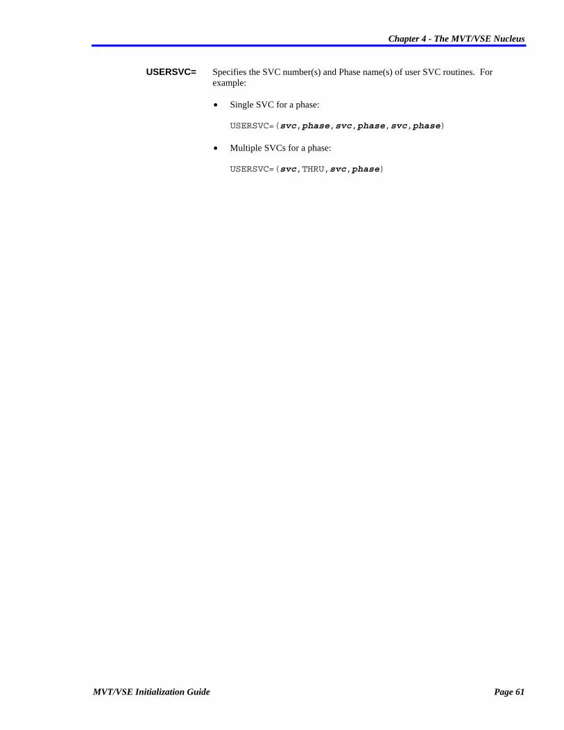
Chapter 4 - The MVT/VSE Nucleus
USERSVC= Specifies the SVC number(s) and Phase name(s) of user SVC routines. For example:
• Single SVC for a phase: USERSVC=(svc,phase,svc,phase,svc,phase)
• Multiple SVCs for a phase: USERSVC=(svc,THRU,svc,phase)
MVT/VSE Initialization Guide Page 61

Chapter 4 - The MVT/VSE Nucleus
NUCOPTN1 The name field for this macro becomes the phase name for the nucleus options phase. The operands may be coded as follows:
NUCOPTN1 op1[,op2[,op3...[,opn]]]
ASCII= ASCII Tape Support Yes Include 512 byte ASCII tables No Default, ASCII tape cannot be processed
EQUATES= Max device equates per region
MODE= Memory type available REAL Default, only real memory can be used VIRTUAL Real and virtual memory can be used
MVTSVC= SVC number for MVT/VSE routines
NLTAS= Number of LTA areas
PAGEIN= Page in requests nn Max PAGEIN requests NO Default, no pagein support generated
PARMLEN= Max PARM length on EXEC JCL statement
REGNS=15 Regions to generate (1-15)
SUBSTM= Sub-systems required ATTNEXIT Generate attention exit support DMS A disk space management system is present EPAT Required if SDI's EPAT is installed ICCF Generate ICCF support INTEL38 Intel/38 support for 3805/3815 PSAM Universal Software's PSAM is present SAMELTA Products that return to same LTA TMS A tape management system is present WESTI Generate WESTI support for local 3270's
SUBTSKS= Number of subtasks in the system
SYSSID= System ID character
Page 62 MVT/VSE Initialization Guide

Chapter 4 - The MVT/VSE Nucleus
Operands/Options
ASCII= Specifies if processing of ASCII format tape is (ASCII=YES) or is not (ASCII=NO) allowed. If YES is specified, the ASCII tables are included.
EQUATES= Defines the maximum number of device equates that are allowed for each region. The default is "EQUATES=20".
MODE= Defines the memory type available for MVT/VSE operation. Valid options are:
REAL Only real memory can be used for system operations. "MODE=REAL" is the default.
VIRTUAL Both real and virtual memory may be used for system operations. "MODE=VIRTUAL" is forced if IPL'ed in ECPS&gml.VSE MODE. VM is handled automatically.
MVTSVC= Specifies the SVC number to be used for MVT/VSE routines. The default is "MVTSVC=174".
NLTAS= The number of LTA areas. Generally these are pooled to reduce the number needed. Each area has a size of 2K. The default is "NLTAS=1".
PAGEIN= The maximum number of page in requests (PAGEIN=nn) allowed or if page in is not allowed (PAGEIN=NO). The maximum value which may be specified is "PAGEIN=65535". The default is "PAGEIN=NO".
PARMLEN= The maximum length of a parameter that is allowed on a JCL EXEC statement. The maximum and default is "PARMLEN=80".
REGNS= The number of regions that are to be generated. The maximum number of regions allowed is 15. The default is "REGNS=15". If "SUBSTM=ICCF" is used, the maximum is "REGNS=12".
SUBSTM= The types of subsystems that are required. Valid options are:
ATTNEXIT Activates support for the user attention exit ($NPATEX).
DMS A disk space management system is present. The actual name is not required.
EPAT Required if SDI's EPAT is installed.
ICCF Generate ICCF support. Note: If ICCF is specified, the maximum number of regions can not exceed 12.
INTEL38 Intel/38 support to be used with the INTEL38 macro for INTEL 3805/3815.
MVT/VSE Initialization Guide Page 63

Chapter 4 - The MVT/VSE Nucleus
PSAM Universal Software's PSAM is present. This option may also be used for other products that require enqueueing of OPEN and CLOSE transients.
SAMELTA Specifies that a product(s) that must return to the same LTA that was last used.
TMS A tape management system is present. If "SUBSTM=EPAT" or "SUBSTM=TFAST" is specified, "SUBSTM=TMS" is assumed.
WESTI Generate WESTI support for local 3270's as described in WESTI manual for double "ENTER" problems. This option must not be used if BTAM is to be used for other local 3270's. The default is that no subsystems will be indicated.
SUBTSKS= The number of subtasks in the system. The maximum allowed is 208 or 35*(# of regions), whichever is less. The minimum allowed is 0.
SYSSID= The one character system identification. This is referred to as the CPUID in conditional JCL and procedure statements. The default is "SYSSID=A".
Page 64 MVT/VSE Initialization Guide

Chapter 4 - The MVT/VSE Nucleus
NUCOPTN2 The NUCOPTN2 macro is used to define system ssembler/compiler and certain job accounting options
The format of the NUCOPTN2 macro is:
NUCOPTN2 op1[,op2[,op3...[,opn]]]
ACANCEL= Auto cancel on JCL error YES Cancel jobs with JCL errors NO Default, ask operator for reply on JCL errors
ALIGN= Align words in assembler YES Default, align data on normal boundaries NO Ignore assembler alignment errors
CHARSET= PL/I character set 60C Default, PL/I coded with EBCDIC 60 character set 48C PL/I coded with EBCDIC 48 character set
DATE= Date configuration MDY Default, date format is MM/DD/YY DMY Date format is DD/MM/YY
DECK= Object deck output YES Default, compilers should output to SYSPCH NO No card deck output
DUMP= Storage dump on ABEND NO Do not print any dumps PART Default, partition dump SDUMP Dump to include the supervisor YES Print storage dump of region on ABENDs
EDECK= Macro edit deck NO Default, do not punch edited macros YES Output edited macro text on SYSPCH
ERRS= Print compiler error messages NO Do not print messages from a compile YES Default, print error messages from a compile
JARPT= Job accounting report options JOB Default, report statistics after each job NO Do not print SYSLST JA reports STEP Report after each step and job
LINES= Default print lines per page
MVT/VSE Initialization Guide Page 65

Chapter 4 - The MVT/VSE Nucleus
LIST= Print compiler source statements NO Do not print source statements YES Default, print source statements input
LISTX= Print compiler object listing NO Default, do not print hex object listing YES Print hex object listing
LOG= Print JCL on SYSLST NO Print only JCL errors on SYSLST YES Default, print all JCL on SYSLST
RLD= Print assembler relocation dictionary NO Default, do not print RLD information YES Print RLD info from the assembler
SKIP= SYSLST paper control between steps NO Space 1 line between job steps YES Default, eject a page after each job step
SXREF= Assembler short XREF option NO Print all symbols in cross reference YES Default, print only referenced material
SYM= Print compiler symbol tables NO Do not print symbol tables YES Default, print data division or symbol table
TERM= Compiler errors to SYSLOG NO Default, no error messages output on SYSLOG YES Print compiler errors messages on SYSLOG
XREF= Print symbol cross reference NO Do not print symbol cross reference YES
Default, print cross reference listing
Operands/options
ACANCEL= Defines if jobs with JCL errors are (ACANCEL=YES) or are not (ACANCEL=NO) to be automatically cancelled. The default is "ACANCEL=NO".
ALIGN= Specifies if alignment of data on proper boundaries is (ALIGN=YES) or is not (ALIGN=NO) to be performed. If "ALIGN=NO" is specified, alignment violations in machine instructions are not diagnosed. The default is "ALIGN=YES".
Page 66 MVT/VSE Initialization Guide

Chapter 4 - The MVT/VSE Nucleus
CHARSET= Defines the type of PL/I character set that is to be used. Valid types are:
60C The EBCDIC 60 character set is used. This is the default.
48C The EBCDIC 48 character set is used.
DATE= Specifies the date configuration that will be used on the system. Valid formats and specifications are:
MDY The date is reported in the format "mm/dd/yy". Where "mm" is the number of the month, "dd" is the day of the month, and "yy" is the current year. This is the default.
DMY The date is reported in the format "dd/mm/yy". Where "dd" is the day of the month, "mm" is the number of the month, and "yy" is the current year.
DECK= Specifies if object deck output is (DECK=YES) or is not (DECK=NO) output from an assembly to SYSPCH. The default is "DECK=YES".
DUMP= Specifies print action for dump processing when a region ABENDs. Valid entries are:
NO The dump is not to be printed.
PART The dump is to be printed. This is the default.
SDUMP The dump is to be printed and will include the supervisor.
YES The dump is to be printed.
EDECK= Specifies if edited macro text is (EDECK=YES) or is not (EDECK=NO) to be output to SYSPUNCH.
ERRS= Specifies if the compiler error messages are (ERRS=YES) or are not (ERRS=NO) to be printed.
JARPT= Specifies how the job accounting statistics output to SYSLST are to be handled. Only one option may be specified. Valid options are:
NO Do not print SYSLST job accounting reports.
JOB Print report statistics after each job. This is the default.
STEP Print report statistics after each step within a job and at the end of the job.
LINES= Specifies the number of lines to be printed on a page of compiler output. The default is "LINES=60". The minimum is 30 and the maximum is 99.
LIST= Specifies if a listing of compiler source statements is (LIST=YES) or is not (LIST=NO) to be produced. The default is "LIST=YES".
MVT/VSE Initialization Guide Page 67

Chapter 4 - The MVT/VSE Nucleus
LISTX= Specifies if a hex listing of the compiled object code is (LISTX=YES) or is not (LISTX=NO) to be produced. The default is "LISTX=NO".
LOG= Specifies the amount of JCL information that is to be printed on SYSLST. Only one option may be specified. Valid options are:
YES All JCL, including errors, is printed on SYSLST. This is the default.
NO Only JCL errors are printed on SYSLST.
RLD= Specifies if the assembler relocation directory is (RLD=YES) or is not (RLD=NO) to be printed. The default is "RLD=NO".
SKIP= Specifies if the paper on the SYSLST device is to eject to a new page (SKIP=YES) after printing job step information, or is to leave a single blank line (SKIP=NO) after printing job step information. The default is "SKIP=YES".
SXREF= Defines if a short version of the assembler cross-reference is to be included in the assembly listing. Valid options are:
YES Includes in the assembler listing a cross-reference table of all symbols that are referenced in the assembly. Any symbols defined but not referenced are not included in the table. This is the default.
NO Includes in the assembler listing a cross-reference table of all symbols used in the assembly. This includes symbols that are defined but never referenced. This is the same as specifying "XREF=YES".
SYM= Indicates if compiler symbol tables or data division information is (SYM=YES) or is not (SYM=NO) to be printed. The default is "SYM=YES".
TERM= Indicates if compiler error messages are (TERM=YES) or are not (TERM=NO) to be output to the SYSLOG device. The default is "TERM=NO".
XREF= Specifies the the full assembler cross-reference table is (XREF=YES) or is not (XREF=NO) to be included in the assembler listing. If "XREF=YES" is specified, the table includes a cross-reference table of all symbols used in the assembly. This includes symbols that are defined but never referenced. The default is "XREF=YES".
Page 68 MVT/VSE Initialization Guide

Chapter 4 - The MVT/VSE Nucleus
NUCOPTN3 The NUCOPTN3 macro is used to specify other general system and accounting options.
The format of the NUCOPTN3 macro is:
NUCOPTN3 op1[,op2[,op3...[,opn]]]
BUFSIZE= Number of copy blocks
CBF= Console buffers to be allocated nn Number to allocate NO Default, no buffers allocated
CHANQ= Number of channel queue entries
DASDFP= DASD file protection NO Default, do not verify if I/O within extents YES Verify each DASD I/O within extents
DATEUPD= Update date at 2400 hours NO Manual update to be done YES Default, automatic update at 2400 hours
EVA= Error Read/Write threshold for warnings (nn,nn) Default is (10,10) NO
JA= Job Accounting Support NO Do not collect job accounting information YES Default, collect job accounting statistics (...) Statistics plus EXCP for indicated regions
JACNT= Format of EXCP counts (if used) CUU Default, collect EXCP counts by device CUU address TYPE Count EXCPs by device type SYSNUM Count EXCPs by SYS number
JACPU= CPU factor for machine units
JALIOCS= Job accounting save area sizes NO No job accounting user save area (N,M) Bytes in user save area and alternate label area * Default, JALIOCS= will determine proper size
MVT/VSE Initialization Guide Page 69

Chapter 4 - The MVT/VSE Nucleus
JALOG= Job accounting record output action ALL Default, output all records (job,step,stop) JOB Output only job summary records NO Do not write any records to disk STEP Output step and job records
JCLGVIS= Amount of extra GETVIS for Job Control
JCLSIZE= Amount of extra memory for JCL
LCONCAT= Max library concatenation for LIBDEF SEARCH
LUBS=[(...)] Max SYS numbers for each region
PSLD= Number of private 2nd level Directory entries nn Default is 12 NO No 2nd level directories
RCBS= Resource conteol blocks specification
REGNLBL= Alter IJSYS labels by region NO Do not alter IJSYS labels YES Default, alter IJSYSIN,LN,01,02,...by region
RPS= LIOCS RPS CCW chain building NO Do not alter LIOCS CCW chains YES Default, alter LIOCS CCW chains to use RPS
SEC= Number of ICCF log queue entries nn NO Default
SLD= Number of SYSRES 2nd level directories nn Default is 5 NO No 2nd level SYSRES directories allowed
SKSEP= 2314 seek separation
SYNCH= Synchronous exit facility use YES Use exit facility NO Default, do not use
TEBV= Tape statistics option CR Combined recording of UL tape errors IR Default, individual error recording for UL tapes
TIMEJOB= Default job time in seconds nn Number of seconds to be used NO Default, no time is used
Page 70 MVT/VSE Initialization Guide
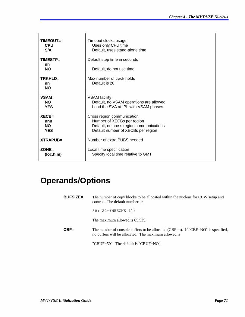
Chapter 4 - The MVT/VSE Nucleus
TIMEOUT= Timeout clocks usage CPU Uses only CPU time S/A Default, uses stand-alone time
TIMESTP= Default step time in seconds nn NO Default, do not use time
TRKHLD= Max number of track holds nn Default is 20 NO
VSAM= VSAM facility NO Default, no VSAM operations are allowed YES Load the SVA at IPL with VSAM phases
XECB= Cross region communication nnn Number of XECBs per region NO Default, no cross region communications YES Default number of XECBs per region
XTRAPUB= Number of extra PUBS needed
ZONE= Local time specification (loc,h,m) Specify local time relative to GMT
Operands/Options
BUFSIZE= The number of copy blocks to be allocated within the nucleus for CCW setup and control. The default number is: 30+(20*(NREGNS-1)) The maximum allowed is 65,535.
CBF= The number of console buffers to be allocated (CBF=n). If "CBF=NO" is specified, no buffers will be allocated. The maximum allowed is "CBUF=50". The default is "CBUF=NO".
MVT/VSE Initialization Guide Page 71

Chapter 4 - The MVT/VSE Nucleus
CHANQ= The maximum number of Channel Queue entries (maximum number of active and pending I/O operations) to be allocated. The maximum number which may be specified is 254. The default is: (#iod)+(cb)+(#dd) Where:
#iod The number of I/O devices defined.
cb The number of Console Buffers defined.
#dd The number of DASD devices defined.
If this operand is omitted, the default calculation will be used.
DASDFP= Specifies if DASD file verification of I/O, within the specified extents, is (DASDFP=YES) or is not (DASDFP=NO) to be performed. The default is"DASDFP=NO".
DATEUPD= Specifies if the system date is to be updated automatically at midnight (DATEUPD=YES) or must be updated manually (DATEUPD=NO) each day. The default is "DATEUPD=YES".
EVA= Specifies the individual volume count thresholds for read and write errors that must be exceeded before warning messages are output. Messages are not output until the error count has exceeded the specified number. The default is "EVA=(10,10)". The maximum number that may be coded is "EVA=(255,255)". If "EVA=NO" is coded, no warning messages will be issued.
JA= Specifies job accounting collection options. Valid options are:
NO No job accounting collection of statistics is performed.
YES Job accounting statistics are collected. This is the default.
(...) Collect job accounting statistics, plus EXCP counts, for each region indicated. Regions are positionally indicated (i.e., "JA=(,8,8,8,,8,8,8,8,8,8,,,,)" would only collect statistics for R2, R3, R4, R6, R7, R8, R9, RA, and RB).
JACNT= Specifies the method to be used when collecting EXCP counts. Valid collection options are:
CUU Collect EXCP counts by individual device address. This is the default.
TYPE Collect EXCP counts by device types.
SYSNUM Collect EXCP counts by SYS assignment number.
The option used for this operand has a direct bearing on the options that may be used on the "CNTDEV=" operand of the NUCEND macro.
Page 72 MVT/VSE Initialization Guide

Chapter 4 - The MVT/VSE Nucleus
JACPU= Defines the CPU model to be used for factoring machine units. If omitted, the system calculates a value based on the CPU model on which MVT/VSE is operating.
JALIOCS= Specifies the size of the area to be used for saving of job accounting data. Valid options are:
NO There is no job accounting user save area.
(n.m) Specifies the number of bytes in the user (n) save area and the alternate (m) label area. If specified, JALIOCS will use the proper size needed for the job accounting routines.
* JALIOCS will determine the proper size to be used for the save and label areas. This is the default.
JALOG= Specifies if job accounting records are to be output to disk and the type of records that are to be output. Valid options are:
ALL Job account records for each job, step and stop are output. This is the default.
JOB Job account records by job only are output to disk.
NO No job accounting records are output to disk.
STEP Job account records are output for each job and step.
JCLGVIS= Specifies the amount of extra GETVIS area that is required by Job Control routines. The number is specified as "nnnK". The default is "JCLGVIS=0".
JCLSIZE= Specifies the amount of extra memory that is required for JCL routines. The number is specified as "nnnK". The default is "JCLSIZE=0".
LCONCAT= Specifies the maximum number of libraries which may be concatenated for a single LIBDEF SEARCH command. The maximum number which may be specified is 15. The default is "LCONCAT=5". The minimum is 1.
LUBS= The maximum number of SYS numbers (SYSxxx) which may be used with all or individual regions. If a single number is specified, all regions are limited to that number. If a group of numbers is specified within parentheses (i.e., LUBS=(n,n,n,n,n...)), the position of the number specified indicates the maximum for a region (R1 = position 1, R2 = position 2, etc.). The minimum is "LUBS=6". The maximum is "LUBS=240". The default is "LUBS=10".
PSLD= Specifies if second level directories are allowed. Valid entries are:
nn The number of second level directories allowed. The default is "PSLD=5". Although there is no actual maximum, the number should be kept as low as possible.
NO Specifies that no second level directories are allowed.
MVT/VSE Initialization Guide Page 73

Chapter 4 - The MVT/VSE Nucleus
RCBS Specifies the number of Resource Control Blocks that are to be allocated for operations. The default is "RCBS=30". The minimum is "RCBS=5" and the maximum is "RCBS=255".
REGNLBL= Specifies if region IJSYS labels will be altered for the specified region(s). Valid entries are:
YES Alter IJSYSIN to the regions indicated (i.e., R1IJSYS, R2IJSYS, etc.). Note that use of REGNLBL=YES also affects the use of standard labels. For example: if you alter the labels for region 1, the standard labels should actually reflect the name R1SYSnn. Where "nn" is 01, PH, LS, IN, etc.
NO Do not alter any IJSYS labels.
RPS= Specifies if Rotational Position Sensing is to be used when building CCW strings. Valid entries are:
YES Alter LIOCS CCW chains for RPS. This is the default.
NO Do not alter LIOCS CCW chains.
SEC= Specifies the number of ICCF log queue entries to be used. Valid entries are:
nn The number of log queue entries to be used.
NO No ICCF log queue entries are to be created. This is the default.
SLD= Specifies the number of SYSRES second level directories that are allowed. Valid entries are:
nn The number of second level SYSRES directories allowed. The default is "SLD=5".
NO No second level SYSRES directories are allowed.
SKSEP= Specifies if 2314 DASD device Seek Separation is (SKSEP=YES) or is not (SKSEP=NO) to be used. The default is "SKSEP=NO".
SYNCH= Specifies if the MVT/VSE Synchronous Exit Facility is (SYNCH=YES) or is not (SYNCH=NO) to be used. The default is "SYNCH=NO".
TEBV= Specifies the tape statistics option for unlabelled tapes (UL). Valid options are:
CR Errors on unlabelled tapes will be combined with other tape errors.
IR Individual error recording will be done for unlabelled tapes. This is the default.
Page 74 MVT/VSE Initialization Guide

Chapter 4 - The MVT/VSE Nucleus
TIMEJOB= Specifies the default time a job should take to complete (also refer to the TIMEOUT= operand). Valid options are:
nn The number of seconds to be used for the default job completion.
NO No time comparison will be used for job completion. This is the default.
TIMEOUT= Specifies the type of timing to be used when determining if a job should be timed out. Valid entries are:
CPU CPU usage time should be used for the timeout.
S/A Stand/Alone time should be used for the timeout. This is the default.
TIMESTP= Specifies if a default time is to be used for each step of a job. Valid options are:
NO No step timing is to be performed. This is the default.
nn The number of seconds that are to be used for default step timing.
TRKHLD= The maximum number of track holds that are allowed. Valid entries are:
nn The number of track holds allowed. The default is "TRKHLD=20". The minimum is "TRKHLD=1" and the maximum is "TRKHLD=255".
NO No track holds are allowed.
VSAM= Specifies VSAM phase loading to the SVA for VSAM functions. Valid options are:
NO VSAM phases are not loaded and no VSAM functions are allowed. This is the default.
YES The VSAM phases are loaded to the SVA at system IPL.
XECB= Specifies if the Cross Region Communication services (XECB) are to be used within the MVT/VSE regions. Valid entries are:
nnn XECBs are to be allowed for the regions and the number specified are to be generated for each region. The minimum is "XECB=4".
NO No XECBs are to be generated for the regions. This is the default.
YES XECBs are to be allowed for the regions and the default of four (4) are to be generated for each region. You should specify "XECB=YES" if you are using the POWER PUTSPOOL, GETSPOOL and CTLSPOOL macros.
XTRAPUB= Specifies the number of extra PUBs that are to be added to the number normally generated automatically by the system. Extra PUBs may be required by certain program products. The default is that the number as calculated by the system will be used or "XTRAPUB=0".
MVT/VSE Initialization Guide Page 75

Chapter 4 - The MVT/VSE Nucleus
ZONE= Specifies the local time differential from Greenwich Mean Time (GMT) in London. The specification is: ZONE=(EAST,hours,mins) WEST For example: New York is 5 hours west of Greenwich and would be specified as: ZONE=(WEST,5,0)
Page 76 MVT/VSE Initialization Guide

Chapter 4 - The MVT/VSE Nucleus
Use Of XTRAPUB In The Nucleus Assembly
The Computer Associates TDYNASN Program requires extra tape devices in the PUB table, starting from address 7F0. XTRAPUB may be specified instead, but the usage is clearer if the devices are actually generated. TFAST/VSE from Tower Systems and EPAT from SDI also require extra pubs. EPAT, however, cannot have dummy devices and must use XTRAPUB for at least 4 extra devices. EPAT additionally needs a dummy device, 7F1 defined (see your EPAT install documentation).
Please comment your listing whenever a product is added which needs dummy pubs.
Editing Macros MVT/VSE is shipped with the DOS/VSE Assembler only.
The DOS/VSE Assembler requires that all macros be "preedited" and reside in the "E." sub-library of the source statement library. The EDECK option is used for this purpose and is described in the "Guide to the DOS/VSE Assembler" manual. Since the DOS/VSE Assembler is the standard assembler for MVT/VSE, all macros shipped in the system source statement library have been edited and are found in the E. Sub-library. If the F Assembler is to be used, the macros must be "unedited" with the ESERV utility program. To assist in editing macros, a procedure named "I.ESERV" is supplied with your system.
If the DOS/VSE Assembler is to be used, all user macros must be edited into the new format. To help identify where all the macros are located and to separate them from any copy books, use the following JCL to scan any source library for MACRO definitions.
// ASSGN SYSSLB,... ANY PRIVATE LIB, ELSE SYSTEM SCANNED // EXEC MVTSCAN,R=AUTO SCAN A.%%%%%%%% VALUE 'MACRO ',COL=(2,16) /*
To assist in editing macros, a procedure named "I.EDECK" is supplied with your system to perform this function.
The DOS/VSE Assembler is distributed under the name ASSEMBLY. These programs may be renamed to any phase name if desired.
MVT/VSE Initialization Guide Page 77


Chapter 5 - Initial Program Load
MVT/VSE Initialization Guide Page 79
Chapter 5 Initial Program Load
This chapter discusses the Initial Program Load (IPL) of the MVT/VSE system and the different options that may be defined during this operation.
The actual IPL of the MVT/VSE system is simple and may be automated to eliminate mistakes in the procedure. The IPL statements may be read from a procedure, tape, card, or diskette. By default, the procedure used for an IPL is J.$IPLPROC. A sample procedure is distributed with the MVT/VSE system.
The IPL Sequence The actual sequence of the MVT/VSE IPL involves several steps. In general, the steps that accomplish the IPL after an IPL is indicated, are:
1. Read and load the "bootstrap" from the SYSRES device.
2. Load specified phases and build a mini nucleus.
3. Read the data contained in $IPLPROC (in the System Source Statement Library).
4. Load the indicated nucleus (default: NUCLEUSA).
5. Process the $IPLPROC statements to build tables.
6. Complete the building of the nucleus and Supervisor area.
7. Transfer control to the Supervisor.
8. Process the $IPLPROC statements.
9. Setup and load the SVA.
At this point, the actual IPL of the MVT/VSE system is complete (message 0I20I is issued). Region 1 is ready for operations.
In most installations, the remainder of the IPL involves the activation of PLF, SPRI, and other program products before the IPL is considered complete. By default, as soon as the 0I20I message is received, the MVT/VSE system will look in the System Procedure Library for the procedure $IPLPRR1. This procedure will call another procedure in the System Source Statement Library with the same name. The procedure in the Source Statement Library can then be used to automate the rest of the IPL.

Chapter 5 - Initial Program Load
Page 80 MVT/VSE Initialization Guide
Automatic IPL
This discussion is a detailed explanation of the events that take place when the MVT/VSE system is IPL'd. It is presented to allow the user to have a better understanding of the IPL sequence and provide information that may be of use in the event of problems with the IPL.
The sequence presented here assumes that a normal IPL is being done. That is, an automatic IPL is to be performed and $IPLPROC is being used for input of the IPL statements and $IPLPRR1 is being used to complete the automatic initialization.
1. Select the IPL device on the CPU.
2. Perform a SYSTEM RESET/CLEAR.
3. Indicate the IPL is to begin (by pressing the "LOAD" button or selecting the IPL option.
4. The SYSRES "bootstrap" is loaded (For CKD devices this is phase $$A$IPL1, for FBA devices the phase is $$A$IPL0). The first 24 bytes of the "bootstrap" are located at Cylinder 0, Track 0, Record 1.
The remainder of the "bootstrap" is loaded from Cylinder 0, Track 0, Record 2 for 144 bytes. The "bootstrap" causes the loading of the phase $$A$PLBK (CKD) or $$A$IPLF (FBA) to begin at location X'3000' of storage. At this point, storage looks like:
End of Real Memory
$$A$PLBK at X'3000'
$$A$IPL0 Start of Real Memory
5. Control is then passed to $$A$PLBK (or $$A$IPLF) which will: • Determine if you are operating in ECPS or S/370 mode. • Determine the "real" memory size. • Determine the SYSRES device type (Read the Format-4 label). • Determine the System Core Image Library extents. • Determine the System Procedure Library extents. • Load phase $$A$IPL3 at the end of "real" memory. • Load phase $$A$IPLR immediately under $$A$IPL3. • Transfer control to $$A$IPLR.

Chapter 5 - Initial Program Load
MVT/VSE Initialization Guide Page 81
If an error is encountered during this phase of the IPL, failure codes are placed in location X'0'. Some of the failure codes are: • C'AS' MACHINE CHECK ON CLEAR CORE 370-M • X'07E6' IPL I/O ERROR • C'0I00A' CORE TOO SMALL • C'0I06A' UNKNOWN SYSRES DEVICE TYPE • C'0I07A' phasename NOT FOUND IN SCIL
6. At this point, the phase $$A$IPLR receives control and will: • Test for proper CPU clock operation. • Test for proper CPU timer operation. • Determine what size storage keys are to be used (2K or 4K). • Loads phase $IJBLBSL to read the $IPLPROC from the Source Statement Library. • Loads phase SPISPARM (Parameter scanner). • Tests if an automatic IPL is to be performed (no external interrupt was found). This is the
point where an external interrupt must be found to indicate an automatic IPL is not to be performed.
• Read the first statement in $IPLPROC to determine if the system console has been defined (SYSLOG=). If this statement is not found, the routine will wait for an "Attention Interrupt" to identify the system console location.
• When the system console is identified, the MVT301I message is displayed indicating that the IPL is in progress. At this point, real memory looks like:
End of Real Memory $$A$IPL3 $$A$IPLR $IJBLBSL
SPISPARM
$$A$PLBK at X'3000'
Start of Real Memory
• Reads the remainder of the $IPLPROC. Some IPL statements are not actually processed as they are read. They are used to create information tables that will be used later in the IPL process (i.e., ADD, DLA, DPD, etc.). The loading of the normal operating nucleus phase is performed when any IPL statement other than: BRANCH, INPUT, PROC, STOP, or SYSLOG is encountered. Installations that use some of these statements, at the front of $IPLPROC PROC, will not load the nucleus until some other IPL statement is actually encountered. Message MVT308I is output when the nucleus is actually loaded. This message indicates: 1. The nucleus phase name used. 2. The volume ID and address of the the SYSRES device. 3. Your CPU identification (CPUID).

Chapter 5 - Initial Program Load
Page 82 MVT/VSE Initialization Guide
4. Any message you may have coded in the NUCEND macro when the nucleus was generated.
• The following items are also performed at this time: 1. Checks for clock and date settings and if the CPU clock is operational. 2. Insures that a DLA statement is present. This statement must always be present. 3. Checks if a DLF statement was included if any DASD was indicated as shared. Checks
for a DPD statement if operating in virtual mode. 4. Creation of a PUB entry for the SYSRES device. If the SYSRES device type was
incorrectly identified in $IPLPROC, the PUB entry is automatically corrected to the proper device type. Note: The SYSRES device type is the only device type that is corrected. Any other statements that contain invalid device types will not be corrected.
5. Creation of a PUB entry for the SYSLOG device. 6. Loads the remainder of the nucleus phases. 7. Loads phase $IPLRT2 immediately behind the nucleus and transfers control to this
phase. 8. Outputs the 0I30I message to display the current date and time.
At this point, the system has begun processing using the normal nucleus and storage looks like:
End of Real Memory
$IPLRT8/9/A
$IPLRT2
SUPERVISOR Start of Real Memory
7. Final initialization of the system is performed by the $IPLRT2 phase. This consists of: • Activation of the CRT task for SYSLOG. • Checks storage operation by clearing all remaining storage. • Building of the AVR tables. Uses phase $IPLRT8 to process the DLA statement. This
includes: 1. Validation of the DLA operands. 2. Open and format (if necessary) of the label area. 3. Output of the 0I52I LABEL AREA message.

Chapter 5 - Initial Program Load
MVT/VSE Initialization Guide Page 83
• Uses phase $IPLRT9 to process the DPD statement. This includes: 1. Checking if the Page Data Set is required. 2. Validation of the DPD statement. 3. Open and formatting (if needed) of the Page Data Set. 4. Output of the 0I52I PDS message.
• Uses phase $IPLRTA to process the DLF statement. This includes: 1. Checking if the Lock File is required (Shared DASD). 2. Validation of the DLF statement. 3. Open and formatting (if needed) of the Lock File area. 4. Output of 0I52I LOCK FILE message
• Loads phase $$A$SVA and its associated load lists that are used for the SVA. Each phase
indicated in the load lists is verified. When this is complete. the lists are sorted and duplicates are removed. This is the point where the actual size of the SVA is calculated. The size used is: LLS + SDL + PSIZE + GETVIS Where:
LLS The size as calculated from all load lists with any duplicates removed.
SDL The amount of storage as calculated from any SDL requirements.
PSIZE Size in the SVA to be reserved for loading phases after the IPL (Specified on the SVA IPL statement)
GETVIS Amount of additional GETVIS to be allocated beyond the minimum size (Specified on the SVA IPL statement).
• $IPLRT2 now completes the IPL process by: 1. Loads phase $ILBRCON to calculate the Library Concatenation Tables size. 2. Loads phase $SVAINIT to establish the SVA and its addresses. 3. Switches to virtual mode if operating in S/370 mode. 4. Loads phase $MAINDIR to perform the actual loading of phases to the SVA. 5. Saves specified entry points for some phases in the SVA. 6. Reloads phase $ILBRCON for final initialization of the library tables. 7. Allocates LUBs and extent blocks in the SVA. 8. Outputs 0I20I IPL COMPLETE message. 9. Issues SVC 14.
At this point, R1 is available and ready for communications.

Chapter 5 - Initial Program Load
Page 84 MVT/VSE Initialization Guide
8. By default, the $IPLPRR1 procedure is searched for at this time. This procedure is located in the System Procedure Library and generally contains a single statement that executes a procedure in the System Source Statement library of the same name. Execution of the procedure in the System Procedure Library is via the statement: // EXEC PROC=$IPLPRR1 The execution of the procedure in the System Source Statement library is via the statement: // EXEC $IPLPRR1 Notice the absence of PROC= in the second example. Any EXEC statement that contains PROC= indicates that the statement is to be read from the System Procedure Library. The absence of PROC= indicates that the procedure is to be read from a System Source Statement Library. It is important to understand that there are two procedures with the same name. One is in the System Procedure Library. The second is in the System Source Statement Library with a sublibrary of "J.". The J.$IPLPRR1 procedure (in the System Source Statement Library) is read to disk and processed. This process is the same as that used for "DISKJCL" processing. This procedure is then used to continue the initialization of your system.

Chapter 5 - Initial Program Load
MVT/VSE Initialization Guide Page 85
The $IPLPROC Procedure
An automatic IPL of MVT/VSE requires that all of the needed IPL statements are in the J.$IPLPROC in the System Source Statement library. The IPL procedure is read and is used to specify the different IPL statements. For example:
.* .* -------> MVT/VSE IPL PROCEDURE .* BRANCH .A100,SERIAL=123456 BRANCH IF SERIAL NUM MATCH BRANCH .A130,SERIAL=000001 BRANCH IF SERIAL NUM MATCH BRANCH .A900 UNKNOWN CPU .* .A100 -------> PROCESS RECOGNIZED CPU .* SYSLOG 009 IDENTIFY CONSOLE DEVICE NUCLEUS NUCLEUSB IDENTIFY NUCLEUS OPTION LOG OPTION MODE=VIRTUAL REAL OR VIRTUAL OPTION (NORPS,NOVSAM,NOVTAM,NOPAGE) SVA GETVIS=120K,PSIZE=200K,SDL=30 SET SVA OPERANDS ADD 00D,TYPE=2540P ... ... ...
As the example indicates, you are able to completely automate the IPL process by the use of a procedure. This procedure can also be use to prompt for special situations. In this way, you can make decisions on what actions are to be taken. This is very useful is situations where you might wish to use an alternate nucleus or define a different SPOOL area.
You can also use the $IPLPRR1 procedure to automate the remainder of the IPL. This procedure is generally used to activate SPRI and other programs (VTAM, CICS, etc.). A sample copy of this procedure is also distributed with the MVT/VSE system.
If you are planning on making any changes to either of these procedures, you should first make a "backup" copy of the unchanged procedure. This allows quick recovery in the event of problems.

Chapter 5 - Initial Program Load
Page 86 MVT/VSE Initialization Guide
Other Types Of IPLs In some instances you may not wish to perform an automatic IPL or interrupt the current IPL. This is done as follows:
Interrupted IPL
This type of IPL is performed when you wish to override the normal IPL procedure. It provides a method of entering IPL statements that you may need to change on a single occasion.
An interrupted IPL is accomplished by starting the IPL and then pressing the INTERRUPT button. This causes the IPL process to being again, but without accessing the automatic IPL procedure.
Since there is no IPL procedure to indicate the location of the operator console, you must specify the location of the console device. This is done by waiting for a couple of seconds and then pressing the ENTER or REQUEST key on the console to be used for the operator console. In some instances, you may press the key too soon and no response will be generated. Press the RESET key and try again.
Note: The first terminal device that sends an interrupt to the system is assumed to be the operator console. You should be sure that no other terminal will be sending an interrupt to the system during this type of IPL.
The system will then request that you enter the IPL statements. At this point, you may:
• Indicate that a procedure is to be used for the IPL by entering: PROC procname This procedure will then be used for the IPL. Or,
• Enter the IPL statements on the console.
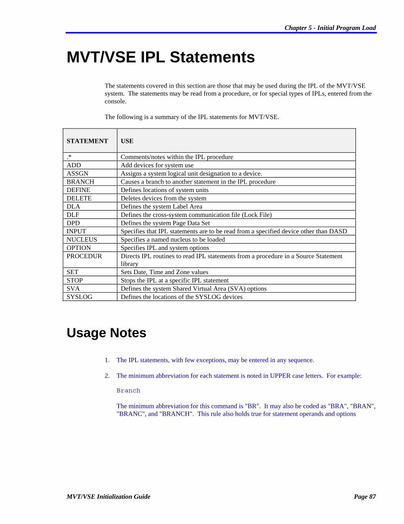
Chapter 5 - Initial Program Load
MVT/VSE Initialization Guide Page 87
MVT/VSE IPL Statements The statements covered in this section are those that may be used during the IPL of the MVT/VSE system. The statements may be read from a procedure, or for special types of IPLs, entered from the console.
The following is a summary of the IPL statements for MVT/VSE.
STATEMENT USE
.* Comments/notes within the IPL procedure ADD Add devices for system use ASSGN Assigns a system logical unit designation to a device. BRANCH Causes a branch to another statement in the IPL procedure DEFINE Defines locations of system units DELETE Deletes devices from the system DLA Defines the system Label Area DLF Defines the cross-system communication file (Lock File) DPD Defines the system Page Data Set INPUT Specifies that IPL statements are to be read from a specified device other than DASD NUCLEUS Specifies a named nucleus to be loaded OPTION Specifies IPL and system options PROCEDUR Directs IPL routines to read IPL statements from a procedure in a Source Statement
library SET Sets Date, Time and Zone values STOP Stops the IPL at a specific IPL statement SVA Defines the system Shared Virtual Area (SVA) options SYSLOG Defines the locations of the SYSLOG devices
Usage Notes
1. The IPL statements, with few exceptions, may be entered in any sequence.
2. The minimum abbreviation for each statement is noted in UPPER case letters. For example: Branch The minimum abbreviation for this command is "BR". It may also be coded as "BRA", "BRAN", "BRANC", and "BRANCH". This rule also holds true for statement operands and options

Chapter 5 - Initial Program Load
Page 88 MVT/VSE Initialization Guide
.* (Comment)
Type: IPL Statement
The .* (comment) statement is used to place a comment anywhere in the IPL procedure.
The format of the .* statement is:
.* [comment...]
The period (.) must be in column 1 and the asterisk (*)must be in column two, followed by at least one blank position. Comments may begin anywhere after column 3.
Examples
... .* ------> CHECK FOR CPU BRANCH .A110,SERIAL=123456 ...
This example shows the .* statement being used to annotate the IPL procedure where a check is being made for the CPU serial number.

Chapter 5 - Initial Program Load
MVT/VSE Initialization Guide Page 89
ADD
Type: IPL Statement
The ADD statement is used to add a device to the system and to define the features associated with that device.
The format of the ADD statement is:
ADD addr[,addr...],TYPE=type[,MODE=mode[,OPTIONS=(...)[PATHS=(...)]]]
addr Required device address(es) cuu Add this single device cuu,cuu... Add these devices
Type=type Required device type
Mode=mode Operation mode of the device
OPTions=(...) Special options to be in effect for the device
PAths=(...) Available paths to the device
Operands/Options
addr This required operand defines the real address of the device or devices being added at IPL time. Specify a single device as: ADD cuu,TYPE=type Specify multiple devices as: ADD cuu,cuu,TYPE=type Devices are added beginning with the first address specified up to and including the last address specified. For example: to add 160 through 168, you would code ADD 160,168,TYPE...
TYPE= This required operand specifies the type of device being added. Valid device types and their descriptions are outlined in Appendix A.
MODE= Specifies the mode of operation for a device. Refer to the IBM publication SC33-6198: VSE/ADVANCED FUNCTIONS: System Control Statements for a more complete description of this operand.

Chapter 5 - Initial Program Load
Page 90 MVT/VSE Initialization Guide
OPTIONS= Defines special operating options that are to be in effect for a device. Valid options are:
CONMAN Specify if the Jason Data Services product CONMAN is to have it's hardcopy file on this device. This is only valid for DASD devices.
DAF Device is connected to multiple controllers. That is, multiple controllers may address this device.
DUAL Disk addresses are paired on the same drive.
DUALNXT Pair this disk with next device.
DUALPR Pair this disk with prior device.
DOWN The device is to be in DVCDN status when the system is IPL'd.
NOMIH Flags devices that should not be handled by the Missing Interrupt Handler.
OFFLINE The device is to be in OFFLINE status when the system is IPL'd.
RPS Device should use RPS features. RPS is assumed if block multiplexor channels are used for RPS device types. Use "TYPE=3340R" for 3340 RPS.
SHARE Device is shared with another CPU. That is, more than one CPU may address this device.
SHRCUE Device is connected to a control unit which can address more than 16 devices (Refer to the section on 'SHARED CONTROL UNIT END INTERRUPTS' in this document).
PATHS= Specifies all available paths to the device. Devices with a single path may share a controller with other multiple path devices. All multiple path devices must share common paths with other devices on the controllers.
Key Points
1. It is recommended that devices be added in device name (cuu) sequence.
2. This sequence is required when more than one ADD statement is used for different devices on the same control unit.

Chapter 5 - Initial Program Load
MVT/VSE Initialization Guide Page 91
3. All combinations of single, double, and triple density 3380 disk drives are supported. No special ADD statement is required since MVT/VSE will query the drive to determine its capacity. Single density drives may be used with out any restrictions. Double and triple density 3380s may be used with the following restriction:
A. Source and Relocatable Libraries may not extend beyond cylinder 1023.
B. It is recommended that all libraries be placed below cylinder 999 because DSERV and other programs which display the disk address of a library member will not show the correct address if it is above cylinder 999.
4. The 3480 Magnetic Tape Subsystem (Tape Cartridge) is supported in code compatibility mode. This includes read/write buffering and support for the automatic cartridge loader in manual and automatic modes. The MVS facilities of DDR (Dynamic Device Reconfiguration), and Processor Assignment are not supported, and neither is System Mode operation of the ACL (Automatic Cartridge Loader). 3480s are defined to the MVT/VSE sytem on the IPL ADD statement by specifying TYPE=3480 and are identified by the PUB Device Type code of x'54'. A mixture of 3410s, 3420s, and 3480s is permitted. Users of 3480s on release 9.1 must remember to change the TYPE= operand on the ADD statement for the 3480s for release 9.2. No changes are required by application programs to make use of 3480s. Checkpoint-Restart also supports the 3480 and will ensure that the contents of the buffer are written to the tape cartridge whenever a checkpoint is taken. Normal error recovery is provided by the subsystem and MVT/VSE examines the Error Recovery Procedure Action (ERPA) returned by the subsystem. If a permanent error is indicated, an OBR record is written to SYSREC.
5. For Guest Systems Under VM:
• Define your DASD as normal. Keep in mind that there may be a possibility of wanting to run MVT/VSE in native mode (without VM). If this is the case, you should try and keep the ADD statements as close to their "real" addresses as possible.
• When defining "minidisks" for MVT/VSE, remember that a single guest system should "own" the DASD devices and all other guest systems should use "links" to those minidisks. The minidisk owning userid should use the "MWV" operand in the VM Directory. For example:
• MDISK entry for "owning" userid: MDISK 120 3350 000 554 MVTRES MWV rpass wpass mpass
• LINK entry for a "sharing" userid: LINK owningid 120 120 MW
Use of the "MWV" operand allows VM to use "virtual" Reserve/Release for the minidisk and any user that may have the minidisk "linked".
• If you are using multiple MVT/VSE systems under VM and are using the Lock File, it is recommended that your install a "virtual" Lock File program product. This type of product will reduce actual I/O to the Lock File.

Chapter 5 - Initial Program Load
Page 92 MVT/VSE Initialization Guide
Examples
ADD 0A0,0AF,TYPE=3277
This example shows 16 3277 type devices being added at addresses 0A0 through 0AF.
ADD 0A0,0AF,TYPE=3277,OPTIONS=(SHRCUE)
This example shows 16 3277 type devices being added at addresses 0A0 through 0AF. The "SHRCUE" option is used to indicate that these devices are on a controller that addresses more than 16 physical devices.
ADD 140,14F,TYPE=3380,OPTIONS=(SHARE,SHRCUE)
This example shows a string of 3380 DASD being added. The "SHARE" option is used to indicate the devices are shared between CPUs. The "SHRCUE" option is used to indicate that these devices are controlled by a controller that will address more than 16 physical devices.
ADD 130,135,TYPE=3350,OPTIONS=(SHRCUE) ADD 136,137,TYPE=3350,OPTIONS=(DOWN)
This is an example of adding devices that do not actually exist. The addresses 136 and 137 are added using the "DOWN" option because they do not exist. Using this option prevents any problems with the controller presenting any type of status for the addresses.
ADD 120,12F,TYPE=3350,OPTIONS=(SHARE,SHRCUE),PATHS=(120,520)
This example shows a string of 3350 DASD being added. The PATHS= operand is used to indicate that the devices may be used at the alternate address of 52x.

Chapter 5 - Initial Program Load
MVT/VSE Initialization Guide Page 93
ADD 120,124,TYPE=3350,OPTIONS=(SHARE,SHRCUE),PATHS=(120,520) ADD 125,TYPE=3350,OPTIONS=(SHARE,SHRCUE,CONMAN) ADD 126,128,TYPE=3350,OPTIONS=(SHARE,SHRCUE),PATHS=(120,520)
This example shows a string of 3350 DASD being added. The 125 address is entered on it's own ADD statement because it contains the CONMAN hardcopy file. Also, note that this address does not have an alternate path defined. This prevents any problems with CONMAN attempting to address the file except on the single address (125).
ADD 450,45F,TYPE=3350,OPTIONS=(SHARE,SHRCUE,DAF)
This is an example of adding devices that may be addressed by more than one controller. This is indicated with the use of the "DAF"option. This is generally used when an installation has two or more CPUs that access the same devices using different controllers.
ADD 180,TYPE=3420T7 ADD 181,187,TYPE=3420T9
This example shows 8 tape drives being added. The first address (180) is a 7-track type drive. The remainder of the drives are 3420 9-track type drives.
ADD 180,TYPE=3420T9,MODE=C8 ADD 181,187,TYPE=3420T9
This example shows 8 tape drives being added. The first address (180) is a 9-track drive with a mode specification of "C8". This is used to indicate a single density 800 BPI drive.

Chapter 5 - Initial Program Load
Page 94 MVT/VSE Initialization Guide
ASSGN
Type: IPL Statement
The ASSGN statement is used to assign a system logical unit designation to a device.
Note: Use of this statement is considered a "permanent" assignment. Any assign made with this statement may be overridden with the //~ASSGN Job Control Statement (A temporary assignment).
The format of the ASSGN statement is:
ASsgn SYSxxx,atype,area
SYSxxx SYS number to assign
atype Assignment type cuu A device address X'cuu' A device address IGN Assign the SYS number to IGNORE UA Unassign the SYS number.
area Effective area of assignment Rx Assignment is for a specific region ALL Assignment affects all regions
Operands/Options
SYSxxx The programmer symbolic SYS number being assigned. "xxx" may be any number from "001" to the maximum SYS number value specified with the "LUBS=" operand of the NUCOPTN3 macro. This is designated by the installation needs.
atype The type of assignment being made. Valid assignments for the symbolic units are:
cuu Assign the SYS number to this device.
X'cuu' Assign the SYS number to this device.
IGN Assign the SYS number to "IGNORE".
UA "UNASSIGN" this SYS number.

Chapter 5 - Initial Program Load
MVT/VSE Initialization Guide Page 95
area Indicates if the assignment is to affect a particular region or all regions. Valid entries are:
Rx The assignment is for this specific region.
ALL The assignment is to be effective for all regions.

Chapter 5 - Initial Program Load
Page 96 MVT/VSE Initialization Guide
BRANCH
Type: IPL Statement
The BRANCH IPL statement is used to cause an unconditional branch to another statement in the IPL procedure. The statement to which the branch is to be taken, must contain a matching symbol as indicated on the BRANCH statement.
The format of the BRANCH statement is:
BRanch symbol,CPUID=,SERIAL=,SYSRES=
symbol Sequence symbol for branch
CPUid= The one character system ID required.
SERial= The CPU serial number required.
SYSres=type
SYSRES device type required.
Operands/Options
symbol Specifies a sequence symbol to which the branch is to be taken (see "Key Points" below).
CUPID= The one character System ID assigned to this system. This MUST be an alphabetic character from "A" to "Z".
SERIAL= The 6 digit serial number of the CPU on which the MVT/VSE system is operating.
SYSRES= The device type being used for the SYStem RESidence device. Valid device types are:
2314 334035 3350 3330 3375 3380 3330B 334075 FBA
Key Points
1. If any of the keyword operands are coded, the branch will only take place if the specified values are correct. This makes the branch conditional. Without these operands, the branch always takes place. If multiple keywords are specified, all of the conditions must be true in order to branch.

Chapter 5 - Initial Program Load
MVT/VSE Initialization Guide Page 97
2. A sequence symbol is a name up to 8 characters long which starts with a period. To indicate a branch point, start the IPL statement with a sequence symbol. The statement will always be treated as a comment and is only of value when used as a branch point.
Examples
BRANCH .A100,SYSRES=3350
The above statement will cause a branch to sequence symbol ".A100" if the SYSRES is on a 3350 type disk.
BRANCH .A200,CPUID=A,SYSRES=3330
The above example will cause a branch to sequence symbol .A200 if the CPUID of the CPU being IPL'd is 'A' and if the SYSRES is on 3330 disk.

Chapter 5 - Initial Program Load
Page 98 MVT/VSE Initialization Guide
DEFINE
Type: IPL Statement
The DEFINE statement is used to define: • The locations of system units, • Total virtual storage size, • Number of system address spaces, • Address space region assignments.
The format of the DEFINE statement is:
DEFine ASPACES=nn
DEFine NOXRM=(Rx[,Rx...])
DEFine SPACE=(...)
DEFine SYSVIS=[NO | YES]
DEFine SYSCAT=cuu[,SYSDMP=cuu[,SYSREC=cuu[,VSIZE=size]]]
DEFine VSIZE=size
ASPACE=nn Number of address spaces to be used
NOXRM=(...) No XRM page use for region(s)
SPACE=(...) Region address space assignments
SYSVIS= System GETVIS restriction for XRM
SYSCAT=cuu The cuu address of SYSCAT
SYSDMP=cuu The cuu address of SYSDMP
SYSREC=cuu The cuu address of SYSREC
VSIZE=size
Virtual storage size

Chapter 5 - Initial Program Load
MVT/VSE Initialization Guide Page 99
Operands/Options
ASPACE= Defines the number of address spaces to be allocated during the IPL. You may specify from 1 to 15 address spaces. You may not use any other operand on a DEFINE statement that contains the ASPACE= operand.
• If this operand is omitted and the "VSIZE=" operand is coded, using another DEFINE statement, a default of "ASPACE=3" will be used.
• If this operand and the "VSIZE=" operand are not coded, using another DEFINE statement, a single address space is used for the entire system (ASPACE=1).
No other operand may be specified on a DEFINE statement when this operand is coded. Use additional DEFINE statements to define other options.
NOXRM= Specifies if a given region is to be restricted to the use of non-XRM page frames (page frames below the 16Mb line). Any region indicated will be restricted in such a manner that it will not use any page frames above the 16Mb line (XRM page frames). Restricting a region in this manner has no affect on the operation of the region. It continues to operate in a normal manner. This DEFINE operand is provided for those types of software that have problems with extended addressing. You may not use any other operand on a DEFINE statement that contains the NOXRM= operand. Coding of regions to be excluded may be done as follows: DEFINE NOXRM=(R4) DEFINE NOXRM=(RA,RC,R3) DEFINE NOXRM=(R2,R3,R4,R5,R6)
SPACE= Specifies the assignment of a region or regions to a specific address space. You may specify a single address space where the indicated region or regions are to run. The address space identification may be:
1-9 A one position number indicating spaces 1 through 9.
A-F A one position alphabetic character indicating spaces A through F.
S The single letter "S" indicating that the system "shared address space" is to be used.
The format of this statement is: DEFINE SPACE=(a,Rx[,Rx[...]]) Where:
a The address space identification being defined (1-9, A-F, or S).

Chapter 5 - Initial Program Load
Page 100 MVT/VSE Initialization Guide
Rx The region/regions to operate in that address space.
When used to assign a region or regions to a specific address space, the address space is reserved for the indicated region/regions only. No other region(s) may run in that address space
No other operand may be used on a DEFINE statement when this operand is coded. You must code additional DEFINE statements to indicate other operands.
SYSCAT= The address (cuu) of the device containing the System Catalog file. This operand is required. This operand may be coded on a DEFINE statement with the SYSDMP and SYSREC operands.
SYSDMP= The address (cuu) of the device containing the System Dump file. If not specified, a default of the SYSRES device will be used. This operand may be coded on a DEFINE statement with the SYSCAT and SYSREC operands.
SYSREC= The address (cuu) of the device containing the System Error Recording file. If not specified, a default of the SYSRES device will be used. This operand may be coded on a DEFINE statement with the SYSCAT and SYSDMP operands.
SYSVIS= This operand is provided to restrict the use of system GETVIS to page frames below the 16Mb line (non-XRM page frames). The values allowed are:
NO This is the default. It indicates that no restrictions are used when obtaining system GETVIS. Storage may be obtained from any available page frame below (non-XRM page frames) or above (XRM page frames) the 16Mb line.
YES Indicates that the system is to be restricted to page frame below the 16Mb line (non-XRM page frames) for system GETVIS. No other operand may be used on a DEFINE statement when this operand is coded. You must code additional DEFINE statements to indicate other operands.
VSIZE= Specifies the total Virtual Storage to be used. You may specify any value between 1024K and 256M. The value may be specified as "nnnK' or as "nnnM". If not specified, a default value of 16 megabytes (16M) is used. Note: If the VSIZE= specification is larger than the total actual size of the Page Dataset allocation (the total of all DPD statements), VSIZE= will be reduced to the actual size of the Page Dataset allocation. No other operand may be specified if this operand is used. You must code additional DEFINE statements to define other options.

Chapter 5 - Initial Program Load
MVT/VSE Initialization Guide Page 101
VSIZE is the sum of the sizes of all Private address spaces, the Shared address space, the SVA, the Real Memory area and the Nucleus. VSIZE may be calculated using the following formula: VSIZE = ( PM * AS ) + ( RSIZE + SVA + SRGNS ) Where:
PM Private Memory size
AS Number of Private address spaces generated at IPL time.
RSIZE The value specified on the RSIZE operand of the IPL OPTION statement.
SVA The size of the Shared Virtual Area.
SRGNS The size of the Shared Regions.
This formula is a "guideline". The actual final value may be increased or decreased depending on your individual operating needs. Most new installations will generally require an "adjustment" period to determine if the VSIZE value is correct or should be adjusted.
Key Points
1. Any region not assigned to an address space will execute in the first available address space where no other regions are assigned. For example: If you have 3 address spaces and R2 is assigned to address space 1 and R3 and R6 are assigned to address space 2, and you start RA, that region will execute in address space 3 (the first available address space that does not have any regions assigned). If you start another region, that region will also execute in address space 3 if that address space has enough remaining storage to process the region.
2. Care must be taken when defining the number of address spaces to be used when assigning regions to address spaces. You must insure that you have storage available for initialization of a region. For example: ... ... DEFINE ASPACES=2 DEFINE SPACE=(S,R1,R4) DEFINE SPACE=(1,RA) DEFINE SPACE=(2,RB) ...

Chapter 5 - Initial Program Load
Page 102 MVT/VSE Initialization Guide
Two address spaces are defined. Notice however that all address spaces are being used. If you were to start another region, that region would not initiate because all available storage is designated for only two address spaces. The started region would issue a message indicating that it was waiting for available storage. Since no storage is available, the region would never process. This problem is avoided by being sure that enough address spaces are defined for any region processing that you may require. In this instance, you might code: ... ... DEFINE ASPACES=5 DEFINE SPACE=(S,R1,R4) DEFINE SPACE=(1,RA) DEFINE SPACE=(2,RB) ... This would allow three additional address spaces for all other regions.
3. As a general rule, it is best to allow MVT/VSE to determine where a region is to execute rather than assign regions to specific address spaces. MVT/VSE is able to determine which address spaces will accomodate a region during initialization. This allows MVT/VSE to provide better overall resource use and throughput. If you have specific questions concerning the assignment of regions (and specific applications) to address spaces, please contact SPI Technical Support for additional guidance.
Examples
DEFINE NOXRM=(RA,R2)
This example shows the DEFINE statement being used to specify that regions A and 2 are to be restricted to the use of non-XRM page frames (page frames below the 16Mb line). All other regions will use any available page frames.
DEFINE SYSVIS=YES
This example shows the DEFINE statement being used to specify that only non-XRM page frames (page frames below the 16Mb line) are to be used for system GETVIS.
DEFINE SYSVIS=NO
This example shows the DEFINE statement being used to specify that any page frame (page frames below and above the 16Mb line) may be used for system GETVIS.

Chapter 5 - Initial Program Load
MVT/VSE Initialization Guide Page 103
DEFINE ASPACE=2
This example shows the DEFINE statement being used to define two (2) private address spaces.
DEFINE SPACE=(S,R1) DEFINE SPACE=(1,RA)
This example shows the DEFINE statement being used to define that specific regions are to run in specific address spaces. In this instance, R1 is to run in the Shared address space (this is the SPRI region) and RA is to run in address space 1. All other regions will be run in any other available address spaces.
DEFINE SYSDMP=122,SYSREC=124,SYSCAT=T123
This example shows the use of the SYSDMP and SYSREC operands. DASD device 122 contains the System Dump file. Device 124 contains the System Error Recording file. Device 123 contains the System Catalog file.
DEFINE VSIZE=24M
This example shows the system virtual storage size being set to 24 megabytes.

Chapter 5 - Initial Program Load
Page 104 MVT/VSE Initialization Guide
DELETE
Type: IPL Statement
The DELETE IPL statement is used to delete devices from the system.
The format of the IPL DELETE statement is:
DELete cuu[,cuu[,cuu...]]
cuu The single address to be deleted.
cuu,cuu
Range of addresses to be deleted.
Operands/Options
cuu The address (cuu) of the device or devices that are to be deleted from system use.
Examples
DELETE 230 DELETE 231 DELETE 232
The above commands will cause devices 230 through 232 to be deleted from thesystem.
DELETE 230,232
This command will accomplish the same purpose as the above command

Chapter 5 - Initial Program Load
MVT/VSE Initialization Guide Page 105
DLA
Type: IPL Statement
The IPL DLA statement is used to define the system Label Area.
DLA start,size[,op1=op[,op2=op[,op3=op[,op4=op]]]]
start Starting location of DLA Blk= FBA starting block number Cylinder= CKD starting cylinder number
size Number of blocks/cylinders NBlk= Number of FBA blocks NCyl= Number of CKD cylinders
Options: Dsf= Data Secured file option No File is not data secured (DEFAULT) Yes File is data secured NAMe= Up to 8 character name for the data set. LABELS Default cccccccc Type= Format options Format Format the label area. Noformat Bypass formatting (DEFAULT). UNIT= Optional device address of the device SYSRES Default cuu
Operands/Options
start The starting location of the Label Area. This location must be specified as:
BLK= For FBA devices only. The starting block of the label area.
CYLINDER= For CKD devices only. The starting cylinder of the label area.
size Specifies the number FBA blocks or CKD cylinders to be used for the Label Area. This must be specified as:
NBLK= For FBA devices only. The number of blocks to be allocated for the label area. The maximum number which may be specified is 992.
NCYL= For CKD devices only. The number of cylinders to be allocated for the label area. The maximum number which may be specified is 8.

Chapter 5 - Initial Program Load
Page 106 MVT/VSE Initialization Guide
DSF= Specifies if the label area is or is not to be data-secured. Valid entries are:
NO The label area IS NOT to be data-secure.
YES The label are IS to be data-secure.
NAME= A 1 to 8 character data set name to be used for the label area.
TYPE= Specifies if the Label Area is or is not to be formatted at IPL time. Valid entries are:
NOFORMAT The label area is not to be formatted. This is the default. If the indicated Label Area cannot be found, a default Label Area is allocated and formatted.
FORMAT The label area will be formatted.
Note: In all instances where the Label Area is formatted, you must re-define the standard labels. This may be done using the STDLABEL procedure.
UNIT= The address (cuu) of the device containing the label area. If not specified, the SYSRES device will be used.
Key Points
1. The format of the Label Area key is:
FIELD DESCRIPTION LENGTH OFFSET 1 File Name 7 0 2 Internal sequence number 1 7
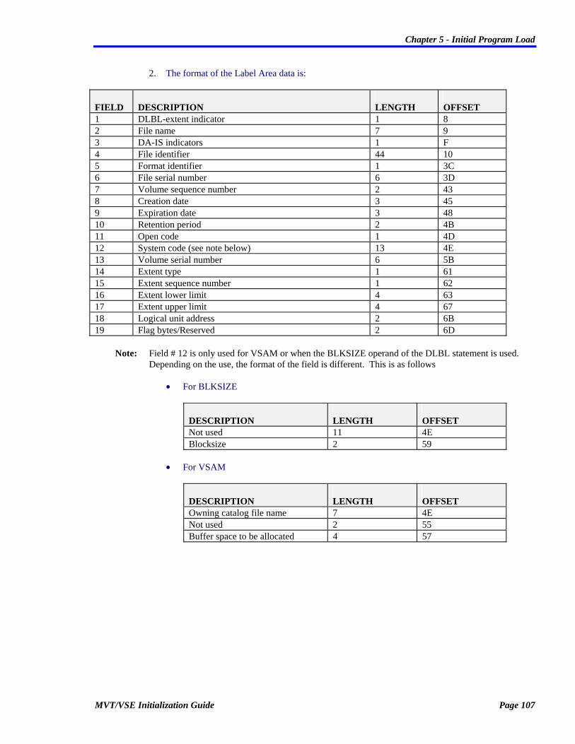
Chapter 5 - Initial Program Load
MVT/VSE Initialization Guide Page 107
2. The format of the Label Area data is:
FIELD DESCRIPTION LENGTH OFFSET 1 DLBL-extent indicator 1 8 2 File name 7 9 3 DA-IS indicators 1 F 4 File identifier 44 10 5 Format identifier 1 3C 6 File serial number 6 3D 7 Volume sequence number 2 43 8 Creation date 3 45 9 Expiration date 3 48 10 Retention period 2 4B 11 Open code 1 4D 12 System code (see note below) 13 4E 13 Volume serial number 6 5B 14 Extent type 1 61 15 Extent sequence number 1 62 16 Extent lower limit 4 63 17 Extent upper limit 4 67 18 Logical unit address 2 6B 19 Flag bytes/Reserved 2 6D
Note: Field # 12 is only used for VSAM or when the BLKSIZE operand of the DLBL statement is used. Depending on the use, the format of the field is different. This is as follows
• For BLKSIZE
DESCRIPTION LENGTH OFFSET Not used 11 4E Blocksize 2 59
• For VSAM
DESCRIPTION LENGTH OFFSET Owning catalog file name 7 4E Not used 2 55 Buffer space to be allocated 4 57

Chapter 5 - Initial Program Load
Page 108 MVT/VSE Initialization Guide
An additional Label Information Record follows the VSAM label record. The format of this record is:
DISK FIELD DESCRIPTION LENGTH OFFSET Key 1 File name 7 0 2 Internal sequence number 1 7 Data 1 File name 1 7 2 Disposition 1 9 3 Records 8 C 4 Record size 4 14

Chapter 5 - Initial Program Load
MVT/VSE Initialization Guide Page 109
DLF
Type: IPL Statement
The DLF statement is used to define the cross-system communication file (Lock File). This file is used when two or more systems share disk storage devices.
The Data Set name used for the Lock file is 'DOS.LOCK.FILE'. This is the same name used for DOS/VSE systems and allows the same Lock
File to be shared between MVT/VSE and DOS/VSE systems.
DLF start,size[,op1=op[,op2=op[,op3=op[,op4=op]]]]
start= Starting block/cylinder Blk= FBA starting block number for the area Cylinder= Starting cylinder number for area
size Size in blocks/cylinders NBlk= Number of FBA blocks for the file NCYl= Number of CKD cylinders for the the file
Options: UNIT= The cuu address of the device SYSRES Default cuu Dsf= Data secured file option No Not a data secured file (DEFAULT) Yes Data secured file NCPu= The number of CPUs supported by the Lock File Type= Noformat Do not format the Lock File (DEFAULT) Format
Format the Lock File
Operands/Options
start Specifies the starting FBA block or CKD cylinder of the Lock File. This must be specified as:
BLK= For FBA devices only. Specifies the starting FBA block number where the Lock File is to begin.
CYLINDER= For CKD devices only. Specifies the starting CKD cylinder number where the Lock File is to begin.
size Specifies the number of FBA blocks or CKD cylinders to be used for the Lock File. This must be specified as:

Chapter 5 - Initial Program Load
Page 110 MVT/VSE Initialization Guide
NBLK= For FBA devices only. Specifies how many FBA blocks are to be allocated for the Lock File.
NCYL= For CKD devices only. Specifies how many CKD cylinders are to be allocated for the Lock File.
DSF= Specifies if the Lock File is to be data-secured. Valid entries are:
NO The Lock File IS NOT to be data-secured. This is the default.
YES The Lock File IS to be data-secured.
NCPU= The number of machines, real or virtual, which share disk storage. The minimum is 2, the maximum is 31. The default value is 'NCPU=8'. If you are using an existing Lock File, the value specified, MUST match the value specified for the existing Lock File. If the values do not match, the Operator has the option of:
1. Continuing the IPL without the use of a Lock File, or
2. Shut down the system and re-IPL specifying the proper value with a new DLF statement.
TYPE= Indicates if the Lock File is or is not to be formatted. Valid entries are:
NOFORMAT The Lock File IS NOT to be formatted. This is the default. If this option is used and the Lock File does not exist on the specified device, a Lock File will be allocated and formatted
FORMAT The Lock File IS to be formatted. If this option is used, you must insure that no other system is accessing the Lock File when it is being formatted. If the Lock File is NOT found on the device when this statement is encountered, the area will be formatted by default.
UNIT= The address (cuu) of the device containing the Lock File. The default is the device containing the SYSRES.
Key Points
1. CAUTION: If "TYPE=FORMAT" is specified, other CPUs that are operational may lose any external locks. This operand should only be used when all other CPUs are inactive.
2. The actual position of the Lock File is at the discretion of the installation.
3. If the Lock File cannot be accessed or used, the Operator is prompted for the type of action to be taken. A reply of 'IGNORE' to message MVT331I will continue the IPL and the Lock File WILL NOT be used. Any other reply will cause the IPL to to issue message 0J31A and enter a Hard Wait status.

Chapter 5 - Initial Program Load
MVT/VSE Initialization Guide Page 111
4. A Lock File is not needed when:
• A single MVT/VSE system is being used, or
• There is no sharing of DASD devices (either real or under VM).

Chapter 5 - Initial Program Load
Page 112 MVT/VSE Initialization Guide
DPD
Type: IPL Statement
The DPD statement is used to define the location(s) of the system Page Data Set(s).
DPD start,size[,op1=op[,op2=op[,op3=op[,op4=op]]]]
start Starting location Blk= FBA Starting block number Cylinder= CKD starting cylinder number
size Size of the area NBlk= Number of FBA blocks for area. NCyl= Number of CKD cylinders for area.
Options: Dsf= Data secured file option No Not data secured (DEFAULT) Yes Data secured file. Reset Force this to be the first extent. Type= Format options Noformat Default, do not format the page data set Format Format the page data set UNIT= Device address SYSRES Default cuu VOLID=
Volume label
Operands/Options
start The starting location of the page data set. This must be specified as:
BLK= For FBA devices only. Specifies the starting FBA block number where the page data set is to begin.
CYLINDER= For CKD devices only. Specifies the starting CKD cylinder number where the page data set is to begin.

Chapter 5 - Initial Program Load
MVT/VSE Initialization Guide Page 113
size The number of FBA blocks or CKD cylinders to be used for the page data set. This must be specified as:
NBLK= For FBA devices only. Specifies how many FBA blocks are to allocated for the page data set.
NCYL= For CKD devices only. Specifies how many CKD cylinders are to allocated for the page data set.
DSF= Specifies if the page data set is to be data-secured. Valid entries are:
NO The page data set IS NOT to be data-secured. This is the default.
YES The page data set IS to be data-secured.
RESET Forces the extents indicated with the BLK=/CYLINDER= and NBLK=/NCYL= operands to become the first (primary) extent for the page data set.
TYPE= Indicates if the page data set is or is not to be formatted. Valid entries are:
NOFORMAT The page data set IS NOT to be formatted. This is the default.
FORMAT The page data set IS to be formatted.
If any of the DPD extents cannot be found on the device, the page data set will be allocated and formatted automatically.
UNIT= The address (cuu) of the device containing the page data set. If UNIT= is not specified, the default is the SYSRES device.
VOLID= The volume identification of the device that is to contain the page data set. VOLID= is used in conjunction with the UNIT= operand. It specifies the volume identification of the DASD device at the address indicated with UNIT=. If VOLID= is used and it does not match the volume identification of the address specified with UNIT=, the IPL is aborted and message MVT329C issued.
Key Points
1. Unless the "RESET" keyword is specified, each DPD statement defines the next Page Data Set extent. Each extent may be on a different device and any mixture of FBA and CKD devices is allowed. Only three extents are allowed on any one device.
2. The "DSF=" operand may be specified on any DPD statement and forces the option for all extents.
3. The size of virtual storage is calculated from the sum of all DPD statements entered.

Chapter 5 - Initial Program Load
Page 114 MVT/VSE Initialization Guide
4. The use of the DPD statement has a direct effect on how the DEFINE VSIZE= operand is used. If the combined total of all DPD statements issmaller than the VSIZE= operand, then VSIZE= will be reduced to the actual size of the page dataset allocation. For example: VSIZE= is set to 64Mb and the total of all DPD statements is 32Mb would cause the VSIZE to be reduced to 32Mb.
5. MVT/VSE uses a page size of 4K when running in 370 Virtual Mode.
Examples
DPD UNIT=120,CYL=20,NCYL=200,DSF=NO,TYPE=NOFORMAT
This statement specifies that a page data set is to be placed on unit 120 for 300 cylinders beginning at cylinder 20. The data secured file option is not to be used and no formatting is to be done.
DPD UNIT=120,CYL=20,NCYL=200,DSF=NO,TYPE=FORMAT
This statement is the same as the previous example except that the data set is to be formatted.
DPD UNIT=34F,VOLID=POOL01,BLK=200,NBLK=200000,DSF=NO,TYPE=NOFORMAT
This statement specifies that a page data set is to be placed on unit 34F for 200000 blocks beginning at block 200. The data secured file option is not to be used and no formatting is to be done. The VOLID= operand is used to verify that the DASD on address 34F has a label of POOL01.
DPD UNIT=130,CYL=10,NCYL=20,DSF=NO,TYPE=NOFORMAT DPD UNIT=130,RESET,CYL=277,NCYL=20,DSF=NO,TYPE=NOFORMAT DPD UNIT=130,CYL=535,NCYL=20,DSF=NO,TYPE=NOFORMAT
These statements show the use of the RESET operand. 3 extents are being defined. The second extent (at the middle of a 3350 DASD) is being defined as the primary (first) page area.

Chapter 5 - Initial Program Load
MVT/VSE Initialization Guide Page 115
INPUT
Type: IPL Statement
This INPUT statement is used to specify that IPL statements are to be read from a specified device other than DASD.
INput cuu,devtype
cuu CUU address of device to be read
devtype The type of input device Cards Input device is card reader Diskette Input device is diskette Tape
Input device is a tape drive
Operands/Options
cuu The real address of the device that is to be used for reading of the IPL statements.
devtype The type of input device from which the IPL statements are to be read. Valid types are:
CARDS The input device is a reader.
DISKETTE The input device is a diskette.
TAPE The input device is a tape drive.
Examples
INPUT 280,TAPE
This statement will cause the IPL statements to be read from a tape on device 280.
INPUT 4C0,DISKETTE
This statement will cause the IPL statements to be read from a diskette device at address 4C0.

Chapter 5 - Initial Program Load
Page 116 MVT/VSE Initialization Guide
INPUT 00C,CARDS
This statement will cause the IPL statements to be read from a reader device at address 00C.

Chapter 5 - Initial Program Load
MVT/VSE Initialization Guide Page 117
NUCLEUS
Type: IPL Statement
The NUCLEUS statement is used to specify a named nucleus to be loaded.
The format of the NUCLEUS IPL statement is:
NUCleus phasename
phasename Name of the nucleus phase to be loaded
Operands/Options
phasename The name of the nucleus phase to be loaded. The phase name may be from 1 to 8 characters in length. If a one character name is specified, it is automatically be prefixed with "NUCLEUS" (i.e., "C" becomes "NUCLEUSC").
Key Points
1. If a NUCLEUS statement is not present in the IPL stream, a default phase name of "NUCLEUSA" is used.
2. The only statements which should precede a nucleus statement are BRANCH, SYSLOG and comments.
3. Specifying a NUCLEUS statement after an options phase has already been loaded will reset all other definitions and IPL statements related to nucleus options.
Examples
... ... NUCLEUS B ... ...
This shows a NUCLEUS statement with a single character phase name indicated. The "B" is prefixed with "NUCLEUS". MVT/VSE looks for and loads a phase with a name of "NUCLEUSB".

Chapter 5 - Initial Program Load
Page 118 MVT/VSE Initialization Guide
... ... NUCLEUS NEWA ... ...
This shows a NUCLEUS statement indicating that the nucleus phase "NEWA" is to be loaded.

Chapter 5 - Initial Program Load
MVT/VSE Initialization Guide Page 119
OPTION
Type: IPL Statement
The IPL OPTION is used to specify IPL and system options.
The format of the OPTION IPL statement is:
OPTion [op1=op[,op2=op[,op3=op[,opn=op]]]
AUTo Perform AUTO IPL procedures
FOrcepf= No VM support for DIAGNISE instruction YES Default NO
IBMNOalt Use IBM standard tape EOT processing for "NO ALTERNATE DRIVE ASSIGNED
LOG Log IPL statements on SYSLOG
Mode= System run mode specifications NOVM Disable VM-assist for nucleus and run real Real Entire system uses real memory Virtual Virtual operation is allowed
NOAuto Do not perform AUTO IPL
NOLog Do not log IPL statements (DEFAULT)
NOPAGe Do not page nucleus (DEFAULT)
NORPS Do not alter LIOCS CCW's for RPS
NOVSAM Do not allow VSAM
NOVTAM Do not allow VTAM
PAGe Page portions of the nucleus
PARM= EXEC PARM= convention MVT Use MVT (OS) convention VSE/SP Use VSE/SP convention
RPS Alter LIOCS CCW's to use RPS
Rsize= V=R storage nnnnK V=R area specified in K nnM V=R area specified in M
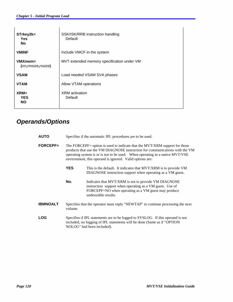
Chapter 5 - Initial Program Load
Page 120 MVT/VSE Initialization Guide
STrkey2k= SSK/ISK/RRB instruction handling Yes Default No
VMINF Include VMCF in the system
VMXmem= MVT extended memory specification under VM (nn,rmsize,rssize)
VSAM Load needed VSAM SVA phases
VTAM Allow VTAM operations
XRM= XRM activation YES Default NO
Operands/Options
AUTO Specifies if the automatic IPL procedures are to be used.
FORCEPF= The FORCEPF= option is used to indicate that the MVT/XRM support for those products that use the VM DIAGNOSE instruction for communications with the VM operating system is or is not to be used. When operating in a native MVT/VSE environment, this operand is ignored. Valid options are:
YES This is the default. It indicates that MVT/XRM is to provide VM DIAGNOSE instruction support when operating as a VM guest.
No. Indicates that MVT/XRM is not to provide VM DIAGNOSE instruction support when operating as a VM guest. Use of FORCEPF=NO when operating as a VM guest may produce undesirable results.
IBMNOALT Specifies that the operator must reply "NEWTAP" to continue processing the next volume.
LOG Specifies if IPL statements are to be logged to SYSLOG. If this operand is not included, no logging of IPL statements will be done (Same as if "OPTION NOLOG" had been included).

Chapter 5 - Initial Program Load
MVT/VSE Initialization Guide Page 121
MODE= Specifies the mode under which the MVT/VSE system is to operate. Valid entries are:
NOVM Disables the VM assist for the nucleus and run in REAL mode.
Real Specifies the MVT/VSE system is to use real memory for all operations.
Virtual Specifies that MVT/VSE will operate in virtual mode.
NOAUTO Specifies that the automatic IPL procedures are not to be used.
NOLOG Specifies that IPL statements are not to be logged to SYSLOG. This is the default.
NOPAGE Specifies that no paging of the nucleus is to be done. This is the default.
NORPS Specifies that no alteration of LIOCS CCWs is to be done.
NOVSAM Specifies that VSAM access method services are not allowed.
NOVTAM Specifies that VTAM access method services are not allowed.
PAGE Specifies that certain portions of the nucleus may be paged out.
PARM= Specifies the type of convention to be used when passing values contained in the PARM= operand of the EXEC statement, to the executing program. Valid values are:
MVT Indicates that the MVT (and OS) standard convention is to be used for the PARM= operand of the EXEC statement. This is as follows:
1. Value present: R1 points to a fullword with bit 0 set to 1 (one), which contains the address of the PARM area. PARMLEN is greater than (>) 0 (zero).
2. PARM= omitted: Register 1 and 15 contain the entry address of the program.
3. Null value: R1 points to a fullword with bit 0 set to 0 (zero), which contains the address of the PARM area. PARMLEN is 0 (zero).

Chapter 5 - Initial Program Load
Page 122 MVT/VSE Initialization Guide
VSE/SP Indicates that the VSE/SP standard convention is to be used for the PARM= operand of the EXEC statement. This is as follows:
1. Value present: R1 points to a fullword with bit 0 set to 1 (one), which contains the address of the PARM area. PARMLEN is greater than (>) 0 (zero).
2. Null value: Register 1 and 15 contain the entry address of the program.
3. PARM= omitted: R1 points to a fullword with bit 0 set to 0 (zero), which contains the address of the PARM area. PARMLEN is 0 (zero).
Note that the conventions for MVT (and OS) when PARM= is omitted or for a null value are exactly the opposite of the convention for VSE/SP. If a PARM= value is present, the conventions are exactly the same.
RPS Specifies that LIOCS CCWs are to be altered to use RPS. S.$SVABAM/S.$SVA0000 should specify the RPS phases to be used.
RSIZE= Indicates:
1. The real memory size to be used for processing by MVT/VSE. This may be specified as "nnnnK" or "nnM".
2. Also indicates that "virtual" memory use will start within the "real" memory of the CPU, not at the end of "real" memory.
STRKEY2K= The STRKEY2K= option is used to disable the MVT/XRM support for the following instructions: • Set Storage Key (SSK - Op Code = 08) • Insert Storage Key (ISK - Op Code = 09) • Reset Reference Bit (RRB - Op Code = B213)
Valid settings are:
YES Indicates that the support for the SSK, ISK, and RRB instruction interface is to be used. MVT/XRM will intercept these instructions and alter them to the extended form of the instructions. This is the default.
NO Indicates that the support for the SSK, ISK, and RRB instruction interface is to be disabled. MVT/XRM will not intercept these instructions and alter them to the extended form of the instructions.
VMINF Specifies that MVT/VSE is to include the VM IUCV (Inter-User Communication Vehicle) and VMCF (Virtual Machine Communication Function) nucleus support within the MVT/VSE system. This option is only valid when using MVT/VSE under VM.

Chapter 5 - Initial Program Load
MVT/VSE Initialization Guide Page 123
VMXMEM= Indicates that MVT/VSE is to operate as a V=R guest machine under a VM operating system and is to use extended memory (memory above the 16Mb line) for its operations. If omitted, MVT/VSE will never attempt to address any storage outside of the V=R area. If an OPTION VMXMEM= statement is used for MVT/VSE operating on a native system, it is ignored. If an OPTION VMXMEM= statement is used for MVT/VSE operating as a V=V guest under VM, the statement is ignored and memory use is limited to that assigned in the VM directory. If an OPTION VMXMEM= statement is used for MVT/VSE and the companion product, VM/XRM is not also installed, the statement is ignored and memory use is limited to the size of the V=R area. If an OPTION VMXMEM= statement is used for MVT/VSE and extended real memory is not available, memory use is limited to the size of the V=R area. Valid option entries are:
nn The amount of V=R storage as designated in the VM directory. This must be the same as that specified in the directory and as generated for the CP V=R area. If the amount of memory specified in this operand is less than the actual amount of the V=R area defined under VM, MVT/XRM will use the actual memory allocated to the V=R area. For example, if you specify: OPTION VMXMEM=(4,nn,nn) and the actual size of the V=R area is 6Mb, MVT/XRM will adjust to use the full 6Mb of the V=R area. If the specification is greater than the size of the V=R area, the entire OPTION VMXMEM= statement is rejected and total memory use is limited to the actual size of the V=R area.
rmsize Indicates the last megabyte of real storage that will be used by CP. This is generally the same value as coded on the SYSCOR RMSIZE= operand of the DMKSYS file. MVT/VSE will begin using the storage immediately following this megabyte in a "dedicated" mode. That is, MVT/VSE will assume that CP will never use any storage above this specification. The minimum specification is 16Mb (i.e., VMXMEM=(xx,16,xx)).

Chapter 5 - Initial Program Load
Page 124 MVT/VSE Initialization Guide
rssize Indicates the ending megabyte of real storage that is to be available to MVT/VSE for dedicated storage operations. This specification is generally:
• The same as that specified in the SYSCOR RSSIZE= operand in the DMKSYS ASSEMBLE file under VM/SP HPO, or
• The ending megabyte of storage that you wish the V=R guest to be able to access. This is generally the same as the actual ending of your real storage.
The maximum specification is 64Mb (i.e., VMXMEM=(xx,xx,64)).
For all MVT/VSE guests operating under VM, the VMXMEM= operand works in conjunction with the OPTION XRM= statement to control the use of extended memory by the guest as follows:
1. If OPTION VMXMEM= is specified, it is negated by a following OPTION XRM=NO statement (extended memory will not be used). For example:
--- --- OPTION VMXMEM=(4,16,32) OPTION XRM=NO --- ---
2. If OPTION VMXMEM= is specified and OPTION XRM=NO is also specified, a following OPTION XRM=YES statement will override the OPTION XRM=NO statement. For example:
--- --- OPTION VMXMEM=(4,16,32) OPTION XRM=NO --- --- OPTION XRM=YES ---
VSAM Specifies that the VSAM access method services SVA phases are to be loaded and VSAM usage is allowed.
VTAM Specifies that the VTAM access method services are allowed.

Chapter 5 - Initial Program Load
MVT/VSE Initialization Guide Page 125
XRM= Specifies it the extended real memory (XRM) is or is not to be used. This operand is ignored for: • MVT/VSE operating native in E-mode (VSE mode). • MVT/VSE operating under VM in VM mode when VM/XRM is not installed
on the VM operating system. • MVT/VSE operating in real mode.
Valid entries are:
YES This is the default. It specifies that MVT/VSE is to attempt to use extended real memory (up to a maximum of 64Mb) if it is available. If an XRM=YES operand is encountered after an XRM=NO operand, the XRM=NO operand is overridden and extended memory will be used. For MVT/VSE guests operating under a VM system, if OPTION XRM=YES is specified and OPTION VMXMEM= is not specified, XRM=YES is ignored.
NO Specifies that MVT/VSE is not to use any memory above the 16Mb line.
This option works in conjunction with other OPTION and DEFINE settings to provide control over the use of extended real memory by the MVT/VSE system.
Key Points
1. IUCV is a facility that allows a program running in a virtual machine to communicate with other programs running in other virtual machines. VMCF is a facility whereby a virtual machine may communicate with another virtual machine. MVT/VSE provides a VM module SPIVMCF which enables CMS users to "talk" to the CRT console of an MVT/VSE guest machine using VMCF. The CMS user may issue commands to AR or respond to any outstanding replies for AR or the regions. Also, the last 20 lines of the console or the last 20 lines for AR or any region may be viewed by the CMS user. SPIVMCF will also accept CP commands from the CMS user, pass them to the MVT/VSE guest machine for execution, and return the result to the CMS user. IUCV support requires that the communication paths be authorized using the VM IUCV directory control statement. If IUCV is supported and paths are authorized for the MVT/VSE virtual machine, programs may use the IUCV protocol to CONNECT, ACCEPT, SEND, RECEIVE and REPLY to programs running on other virtual machines and thereby transfer data between them. The macros VSIUCV, VSIUCVPL, and VSIUCVU are provided for use with IUCV for user calls, user parameter lists, and user identification blocks respectively.

Chapter 5 - Initial Program Load
Page 126 MVT/VSE Initialization Guide
For detailed information on both VMCF and IUCV refer to the appropriate VM manual such as VM/SP "System Facilities for Programming" (SC24-5288).
2. When using the VMXMEM= operand of this statement, you must be sure that the specifications are coordinated with your VM systems personnel. Prior to using this feature, you should check the following:
• A V=R area is specified in the CP nucleus and the nucleus is properly loaded.
• The MVT/VSE guest machine VM directory entry properly reflects the V=R area size. For example: If you specify a 12 Mb V=R area in VM, the MVT/VSE guest machine directory entry might be:
USER userid pswd 12M 12M BCG pri
and the OPTION VMXMEM= entry must be:
OPTION VMXMEM=(12,xx,xx)
• If MVT/VSE is to use high storage not used by CP, The SYSCOR macro operands:
RMSIZE= Is properly coded to reflect the maximum amount memory that is to be used by CP (For both VM/SP and VM/SP HPO).
RSSIZE= Is properly coded to reflect the total amount of storage available on the CPU (For VM/SP HPO systems only).
Examples
OPTION FORCEPF=NO
This shows an example of FORCEPF= being used to disable the VM DIAGNOSE interface. Use of this FORCEPF= option is notrecommended when operating as a VM guest.
OPTION VMXMEM=(08,16,24)
This example shows the VMXMEM= operand being used to define an MVT/VSE guest machine under VM. It will operate in an 8 Mb (08) V=R area and may use the additional storage above the 16Mb line up to and including, the 24th Mb.
OPTION STRKEY2K=YES

Chapter 5 - Initial Program Load
MVT/VSE Initialization Guide Page 127
This example shows the use of the STRKEY2K= control statement that will use the MVT/XRM interface for the ISK, SSK and RRB intercept routines. These instructions will be intercepted and changed to the extended format of the instructions.
OPTION STRKEY2K=NO
This example shows the use of the STRKEY2K= control statement being used to disable the MVT/XRM interface for the ISK, SSK and RRB intercept routines. These instructions will not be intercepted and changed to the extended format of the instructions.

Chapter 5 - Initial Program Load
Page 128 MVT/VSE Initialization Guide
PROCEDUR
Type: IPL Statement
The PROCEDUR IPL statement is used to direct the IPL routines to read IPL statements from a procedure.
Nested procedures are not allowed. Control is always transferred to the new procedure. During Automatic IPL, the J.$IPLPROC procedure is used.
The format of the IPL PROCEDUR statement is:
PRocedur [s.]libname
[s.]
libname
Use this sublibrary
Name of the procedure to use
Operands/Options
[s.]libname The name of the procedure that contains the IPL statements. You may optionally code a sublibrary. The default sublibrary is "J".

Chapter 5 - Initial Program Load
MVT/VSE Initialization Guide Page 129
SET
Type: IPL Statement
This statement is used to:
• Set Date, Time and Zone values and
• SQL VM/CICS information
Although all operands are optional, at least 1 operand must be coded.
The format of the IPL SET statement is:
SET [CLock=hh/mm/ss[,Date=date[,SYSdate=date[,ZONE=(area/hh/mm)]]]]
SET APPCVM=[(]resid[,gateway,tlu,mode)][,XPCC=subsystem]
APPCVM= resid VM SQL server userid (r,g,t,m) Network routing information
CLock= Time of day (hh/mm/ss)
Date= Date to set (mm/dd/yy or dd/mm/yy)
SYSDate= Date to set (mm/dd/yy or dd/mm/yy)
XPCC=subsystem XPCC subsystem name
Zone= Local zone value in relation to Greenwich WEST/hh/mm West of Greenwich EAST/hh/mm East of Greenwich
Operands/Options
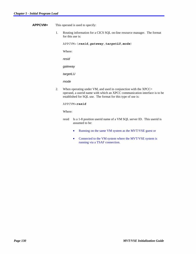
Chapter 5 - Initial Program Load
Page 130 MVT/VSE Initialization Guide
APPCVM= This operand is used to specify:
1. Routing information for a CICS SQL on-line resource manager. The format for this use is: APPCVM=(resid,gateway,targetLU,mode) Where:
resid
gateway
targetLU
mode
2. When operating under VM, and used in conjunction with the XPCC= operand, a userid name with which an XPCC communication interface is to be established for SQL use. The format for this type of use is: APPCVM=resid Where:
resid Is a 1-8 position userid name of a VM SQL server ID. This userid is assumed to be:
• Running on the same VM system as the MVT/VSE guest or
• Connected to the VM system where the MVT/VSE system is running via a TSAF connection.
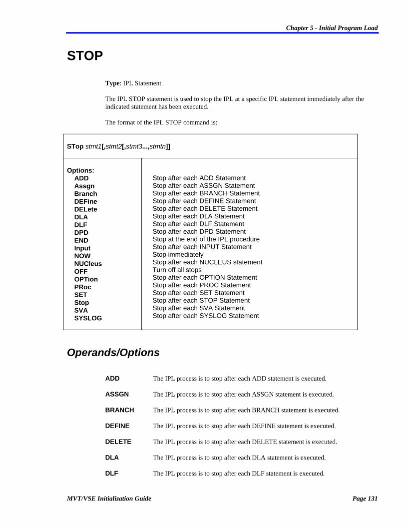
Chapter 5 - Initial Program Load
MVT/VSE Initialization Guide Page 131
STOP
Type: IPL Statement
The IPL STOP statement is used to stop the IPL at a specific IPL statement immediately after the indicated statement has been executed.
The format of the IPL STOP command is:
STop stmt1[,stmt2[,stmt3...,stmtn]]
Options: ADD Assgn Branch DEFine DELete DLA DLF DPD END Input NOW NUCleus OFF OPTion PRoc SET Stop SVA SYSLOG
Stop after each ADD Statement Stop after each ASSGN Statement Stop after each BRANCH Statement Stop after each DEFINE Statement Stop after each DELETE Statement Stop after each DLA Statement Stop after each DLF Statement Stop after each DPD Statement Stop at the end of the IPL procedure Stop after each INPUT Statement Stop immediately Stop after each NUCLEUS statement Turn off all stops Stop after each OPTION Statement Stop after each PROC Statement Stop after each SET Statement Stop after each STOP Statement Stop after each SVA Statement Stop after each SYSLOG Statement
Operands/Options
ADD The IPL process is to stop after each ADD statement is executed.
ASSGN The IPL process is to stop after each ASSGN statement is executed.
BRANCH The IPL process is to stop after each BRANCH statement is executed.
DEFINE The IPL process is to stop after each DEFINE statement is executed.
DELETE The IPL process is to stop after each DELETE statement is executed.
DLA The IPL process is to stop after each DLA statement is executed.
DLF The IPL process is to stop after each DLF statement is executed.

Chapter 5 - Initial Program Load
Page 132 MVT/VSE Initialization Guide
DPD The IPL process is to stop after each DPD statement is executed.
END The IPL process is to stop at the end of the IPL procedure.
INPUT The IPL process is to stop after each INPUT statement is executed.
NOW The IPL process is to stop IMMEDIATELY.
NUCLEUS The IPL process is to stop after each NUCLEUS statement is executed.
OFF All previous STOP statements are turned off.
OPTION The IPL process is to stop after each OPTION statement is executed.
PROC The IPL process is to stop after each PROC statement is executed.
SET The IPL process is to stop after each SET statement is executed.
STOP The IPL process is to stop after each STOP statement is executed.
SVA The IPL process is to stop after each SVA statement is executed.
SYSLOG The IPL process is to stop after each SYSLOG statement is executed.

Chapter 5 - Initial Program Load
MVT/VSE Initialization Guide Page 133
SVA
Type: IPL Statement
This IPL SVA statement is required and used to define system Shared Virtual Area (SVA) options.
Refer to IBM publication SC33-6198 System Control Statements for a full discussion of the SVA IPL Statement.
The format of the IPL SVA command is:
SVA [GETvis=nnnK[,PSize=nnn[,SDL=nnn]]]
GETvis=
Psize=
SDL=
Extra system GETVIS space expressed as nnnK
Reserve space for user phases
Specifies the decimal number of entries in the systemdirectory list to be reserved for phases in addition to the phases loaded automatically during IPL
Operands/Options
GETVIS= Specifies additional GETVIS space that is to be made available in addition to that allocated by the system. The value is specified as nnnK.
PSIZE= Specifies the size of the area within the SVA which is to be reserved for phases which will be loaded into the SVA after the IPL (referred to a "user" phases).
SDL= Specifies the decimal number of entries in the system directory list (SDL) to be reserved for phases in addition to the phases loaded automatically during IPL.

Chapter 5 - Initial Program Load
Page 134 MVT/VSE Initialization Guide
SYSLOG
Type: IPL Statement
The IPL SYSLOG statement is used to define the locations of the SYSLOG devices.
The format of the SYSLOG IPL statement is:
SYSLOG con-cuu,prt-cuu
con-cuu Address of console device.
prt-cuu Address of console printer
Operands/Options
con-cuu Specifies the address of the device to be used for the system console.
prt-cuu Specifies the address of the device to be used for the console printer.
Key Points
1. If operating as a guest under a VM operating system, It is best to not use the SYSLOG statement. This prevents any problems with conflicts between the actual terminal you are actually using and how it is defined to the MVT/VSE guest. MVT/VSE will automatically adjust the SYSLOG device for the type of device being used.

Appendix A - Examples of IPLStatements Use
MVT/VSE Initialization Guide Page 135
Appendix A Examples of IPLStatements Use
This appendix is provided as a general guide to the types of IPL statements that might be used to indicate how the MVT/VSE system is being used.

Appendix A - Examples of IPLStatements Use
Page 136 MVT/VSE Initialization Guide
VAE Mode This examples shows the use of the IPL statements for: • MVT/VSE in VAE mode • Virtual storage size of 30M • 3 private address spaces • SPRI as a shared region in R1 • 2 strings of 3380 DASD with a shared controller and dual pathing • No Lock file because there is no shared DASD
.. ADD 00E,TYPE=3211 ... ADD 130,14F,TYPE=3380,OPTION=(SHRCUE,DAF),PATHS=(130,330) ... ... OPTION MODE=VIRTUAL Define 370 paging mode DEFINE VSIZE=30M Define system virtual storage DEFINE ASPACE=3 Allocate 3 address spaces DEFINE SPACE=(S,R1) R1 contains shared SPRI region DPD CYL=..... Allocate 30M of virtual storage DPD CYL=..... via page dataset definition DPD CYL=..... statements across several DASD ...

Appendix A - Examples of IPLStatements Use
MVT/VSE Initialization Guide Page 137
VAE Mode Under VM This example is the same as the previous example, except that the MVT/VSE system is to be run as a VM guest. This is generally used for testing of MVT/VSE and other components/products.
~... ADD 00E,TYPE=3211 ~... ADD 130,14F,TYPE=3380,OPTION=(SHRCUE,DAF),PATHS=(130,330) ~... ~... OPTION MODE=NOVM Disable VM assist to force real OPTION MODE=VIRTUAL Define 370 paging mode DEFINE VSIZE=30M Define system virtual storage DEFINE ASPACES=3 Allocate 3 address spaces DEFINE SPACE=(S,R1) R1 contains shared SPRI region DPD CYL=..... Allocate 30M of virtual storage DPD CYL=..... via page dataset definition DPD CYL=..... statements across several DASD ~...

Appendix A - Examples of IPLStatements Use
Page 138 MVT/VSE Initialization Guide
VAE Mode This examples shows the use of the IPL statements for: • MVT/VSE in VAE mode • Two strings of 3350 DASD on two channels while sharing with another CPU (no alternate/dual
pathing) • CONMAN hardcopy file on 14C • Virtual storage size of 256M • 4 private address spaces • R1 (SPRI) and R2 (VTAM) regions in a shared address space • CICS (R3) in address space 4
ADD 140,14B,TYPE=3350,OPTION=(SHARE,SHRCUE) ADD 14C,TYPE=3350,OPTION=(SHRCUE,CONMAN) ADD 14D,14F,TYPE=3350,OPTION=(SHARE,SHRCUE) ADD 350,35F,TYPE=3350,OPTION=(SHARE,SHRCUE) ~... DLF CYL... Lock file use ~... DEFINE VSIZE=256M Define system virtual storage DEFINE ASPACES=4 Allocate 4 address spaces DEFINE SPACE=(S,R1,R2) Assign shared regions DEFINE SPACE=(4,R3) Assign CICS(R3) to address space DPD CYL=..... Allocate 256M of virtual storage DPD CYL=..... via page dataset definitions DPD CYL=..... across several dasd volumes: DPD CYL=..... " DPD CYL=..... " DPD CYL=..... "

Appendix A - Examples of IPLStatements Use
MVT/VSE Initialization Guide Page 139
VAE Mode This examples shows the use of the IPL statements for: • MVT/VSE in VAE mode • 8 private address spaces • Virtual storage size of 256M • R1 (SPRI) and R2 (VTAM) regions in a shared address space • CICS (R3) in address space 2 • CICSTEST (RB) in address space 3 • Batch regions R4 and R5 in address space 4 • Compiler regions R6 and R7 in address space 5
ADD ... ~... ~... DEFINE VSIZE=256M Define system virtual storage DEFINE ASPACES=8 Allocate 8 address spaces DEFINE SPACE=(S,R1,R2) Assign shared regions DEFINE SPACE=(2,R3) Assign R3 to address space DEFINE SPACE=(3,RB) Assign RB to address space DEFINE SPACE=(4,R4,R5) Assign R4,R5 to address space DEFINE SPACE=(5,R6,R7) Assign R6,R7 to address space DPD ......... Allocate 256M of virtual storage DPD ......... via page dataset definitions DPD ......... across several dasd volumes: DPD ......... " DPD ......... " DPD ......... " ~...

Appendix A - Examples of IPLStatements Use
Page 140 MVT/VSE Initialization Guide
VM Mode This examples shows the use of the IPL statements for: • MVT/VSE under VM • 2 strings of 3350 DASD not shared with any other CPU • DASD devices 36C through 36F are not installed. • CONMAN Hardcopy File on 248 • Virtual printers (treated as "real" by MVT/VSE and SPRI) at 01E and 01F.
ADD 01E,TYPE=PRT1 ADD 01F,TYPE=3211 ADD 240,247,TYPE=3350,OPTION=(SHRCUE) ADD 248,OPTION=(SHRCUE,CONMAN) ADD 249,24F,TYPE=3350,OPTION=(SHRCUE) ADD 360,36B,TYPE=3350,OPTION=(SHRCUE) ADD 36C,36F,TYPE=3350,OPTION=(SHRCUE,DOWN) ADD 36C,36F,TYPE=3380,OPTION=(SHRCUE,CONMAN)

Appendix B - Supported Device Types
MVT/VSE Initialization Guide Page 141
Appendix B Supported Device Types
The following is a complete list of all devices currently supported by the MVT/VSE operating system.
As new devices are introduced and support is added to MVT/VSE, they will be added to this list. If you have any questions about a specific device type, please contact Software Pursuits Technical Support.

Appendix B - Supported Device Types
Page 142 MVT/VSE Initialization Guide
Communications Devices Device Description MVT/VSE Designation
2701 Type Line Adapter 2701
2702 Type Line Adapter 2702
2702 Type Line Adapter - SAD0 2702A
2702 Type Line Adapter - SAD1 2702B
2702 Type Line Adapter - SAD2 2702C
2702 Type Line Adapter - SAD3 2702D
2703 Transmission control unit 2703
3704 Communications Controller 3704
3705 Communications Controller 3705
3720 Communications Controller 3705
3725 Communications Controller 3705
3791L Local Control Unit 3791L
3791 Local Attached Cluster Controller LCA2

Appendix B - Supported Device Types
MVT/VSE Initialization Guide Page 143
Consoles And Terminals Device Description MVT/VSE Designation
Display Operator Console 125D
Display Operator Console with Printer 125DP
1052 Console 1050A
1052 Console 1052
2260 Display Station 2260
3210 Console 3210
3215 Console 3215
3270 Local Terminal 3270
327x Terminal 3277
3277B Terminal (Burst) 3277B

Appendix B - Supported Device Types
Page 144 MVT/VSE Initialization Guide
DASD Devices Device Description MVT/VSE Designation
2311 DASD 2311
2314 DASD 2314
3330 DASD 3330
3330 Model B DASD 3330B
3340 DASD 3340
3340-36 DASD 334036
3340-70 DASD Device 334070
3340-R DASD 3340R
3350 DASD 3350
3375 DASD 3375
3380 DASD (All models) 3380
All FBA DASD Devices FBA

Appendix B - Supported Device Types
MVT/VSE Initialization Guide Page 145
MICR Devices Device Description MVT/VSE Designation
1419 MICR Reader 1419
1419 Primary MICR Address 1419P
1419 Secondary MICR Address 1419S
2956 Primary MICR Address 2956P
2956 Secondary MICR Address 2956S

Appendix B - Supported Device Types
Page 146 MVT/VSE Initialization Guide
Printer Devices Device Description MVT/VSE Designation
Advanced Function Printers AFP
1017 Printer with 2826 Model 2 controller 1017TP
1018 Printer with 2826 Model 2 controller 1018TP
1403 Printer 1403
1403 Printer With UCS feature 1403U
1443 Printer 1443
2245 Printer 2245
3203 Printer 3203
3211 Printer 3211
328x Printer 3277
32xx Printer in burst mode 3277B
3800 Printer 3800
3800 Printer with Burster 3800B
3800 Printer with GCS 3800C
3800 Printer with GCS and Burster 3800BC
4248 Printer 4248
5203 Printer 5203
5203 Printer with GCS 5203U
Generic Printer (3211, 3203-4/5, etc) PRT1

Appendix B - Supported Device Types
MVT/VSE Initialization Guide Page 147
Reader/Punch Devices Device Description MVT/VSE Designation
1017 Paper Tape Reader 1017
1018 Paper Tape Punch 1018
1287 Optical Reader 1287
1288 Optical Reader 1288
1442 Card Reader/Punch 1442N1
1442 Card Punch 1442N2
2501 Card Reader 2501
2520-B2 Card Punch 2520B2
2520-B3 Card Punch 2520B3
2520-B1 Card Reader/Punch 2530B1
2540 Card Reader 2540R
2540 Card Punch 2540P
2596 Card Reader/Punch 2596
2671 Paper Tape Reader 2671
3504 Card Reader 3504
3505 Card Reader 3505
3525 Card Punch 3525P
3525 Card Reader/Punch 3525RP
3881 Optical Mark Reader 3881
3886 Optical Character Reader 3886
3890 Document Reader 3890
3895 Reader/Inscriber 3895

Appendix B - Supported Device Types
Page 148 MVT/VSE Initialization Guide
Tape Devices Device Description MVT/VSE Designation
Generic 2400 Tape Drive 2400
2400 7-Track Tape Drive 2400T7
2400 9-Track Tape Drive 2400T9
8809 Tape Drive 3401
Generic 3410 Tape Drive 3410
3410 7-Track Tape Drive 3410T7
3410 9-track Tape Drive 3410T9
Generic 3420 Tape Drive 3420
3420 7-track Tape Drive 3420T7
3420 9-track Tape Drive 3420T9
3422 Tape Drive 3422
3430 Tape Drive 3430
3480 Tape Drive 3480
8809 Tape Drive 8809

Appendix B - Supported Device Types
MVT/VSE Initialization Guide Page 149
Miscellaneous Devices Device Description MVT/VSE Designation
2560 Multi-function Control unit 2560
3540 Diskette Reader 3540
5425 Multi-function Control unit 5425
7443 System Recording File 7443
7770 Audio Response Unit 7770
7772 Audio Response Unit 7772
Channel To Channel Adapter CTCA

Appendix B - Supported Device Types
Page 150 MVT/VSE Initialization Guide
Unsupported Devices Device Description MVT/VSE Designation
Unsupported Device UNSP
Unsupported Burst Device UNSPB
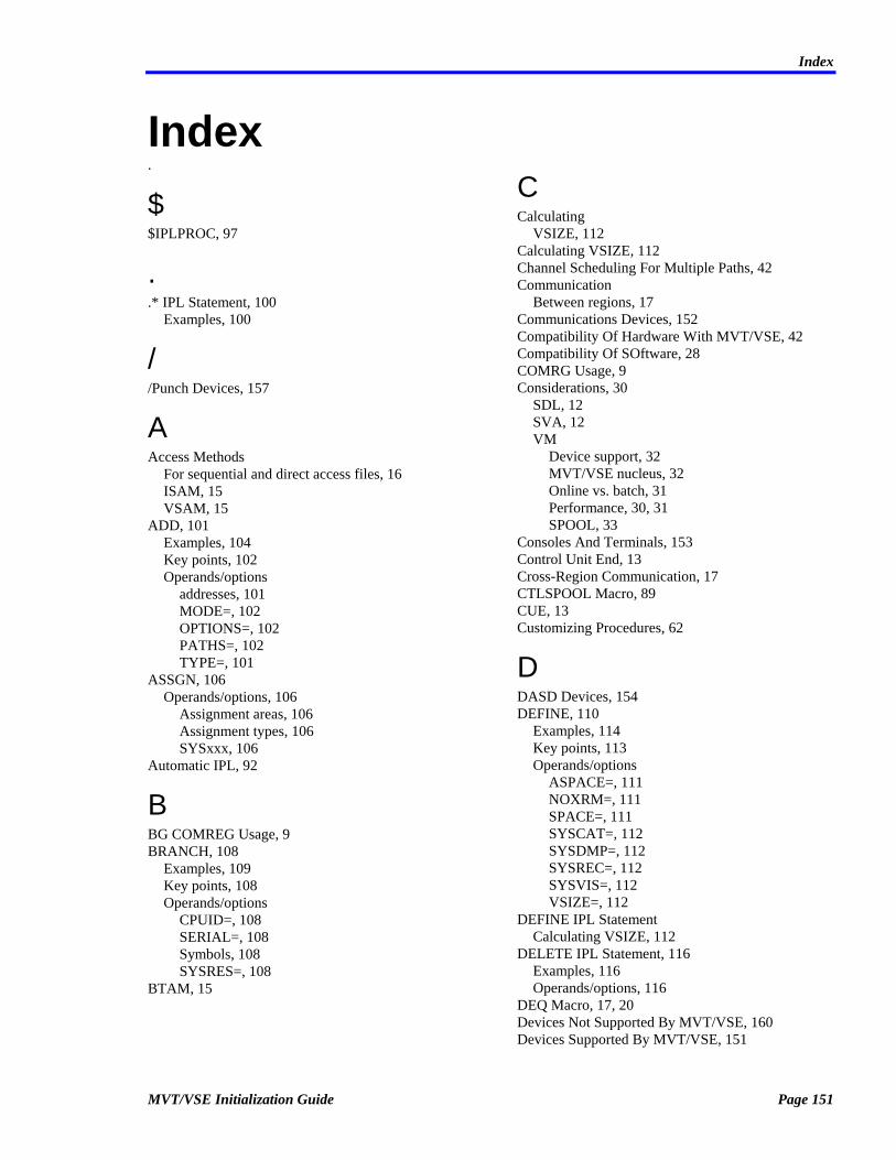
Index
Index .
$ $IPLPROC, 97
.
.* IPL Statement, 100 Examples, 100
/ /Punch Devices, 157
A Access Methods
For sequential and direct access files, 16 ISAM, 15 VSAM, 15
ADD, 101 Examples, 104 Key points, 102 Operands/options
addresses, 101 MODE=, 102 OPTIONS=, 102 PATHS=, 102 TYPE=, 101
ASSGN, 106 Operands/options, 106
Assignment areas, 106 Assignment types, 106 SYSxxx, 106
Automatic IPL, 92
B BG COMREG Usage, 9 BRANCH, 108
Examples, 109 Key points, 108 Operands/options
CPUID=, 108 SERIAL=, 108 Symbols, 108 SYSRES=, 108
BTAM, 15
C Calculating
VSIZE, 112 Calculating VSIZE, 112 Channel Scheduling For Multiple Paths, 42 Communication
Between regions, 17 Communications Devices, 152 Compatibility Of Hardware With MVT/VSE, 42 Compatibility Of SOftware, 28 COMRG Usage, 9 Considerations, 30
SDL, 12 SVA, 12 VM
Device support, 32 MVT/VSE nucleus, 32 Online vs. batch, 31 Performance, 30, 31 SPOOL, 33
Consoles And Terminals, 153 Control Unit End, 13 Cross-Region Communication, 17 CTLSPOOL Macro, 89 CUE, 13 Customizing Procedures, 62
D DASD Devices, 154 DEFINE, 110
Examples, 114 Key points, 113 Operands/options
ASPACE=, 111 NOXRM=, 111 SPACE=, 111 SYSCAT=, 112 SYSDMP=, 112 SYSREC=, 112 SYSVIS=, 112 VSIZE=, 112
DEFINE IPL Statement Calculating VSIZE, 112
DELETE IPL Statement, 116 Examples, 116 Operands/options, 116
DEQ Macro, 17, 20 Devices Not Supported By MVT/VSE, 160 Devices Supported By MVT/VSE, 151
MVT/VSE Initialization Guide Page 151

Index
Communications Devices, 152 Consoles, 153 DASD Devices, 154 MICR Devices, 155 Miscellaneous Devices, 159 Printer Devices, 156 Punch Devices, 157 Reader Devices, 157 Tape Devices, 158 Terminals, 153
Disk Space allocations at installation, 61
DLA, 117 Operands/options
CYLINDER=, 117 DSF=, 118 NAME=, 118 NBLK=, 117 TYPE=, 118 UNIT=, 118
DLF, 120 Key points, 121 Operands/options
BLK=, 120 DSF=, 121 NBLK=, 121 NCPU=, 121 TYPE=, 121 UNIT=, 121
DPD, 123 Examples, 125 Key points, 124 Operands/options
BLK=, 123 DSF=, 124 NBLK=, 123 TYPE=, 124 UNIT=, 124 VOLID=, 124
E E.EDECK, 90 Editing Macros, 90
I.EDECK, 90 ENQ Macro, 17, 19 ENQRELSE Macro, 20 Examples
.* IPL statement, 100 ADD, 104 BRANCH, 109 DEFINE, 114 DELETE IPL statement, 116 DPD, 125 INPUT, 126
NUCASSGN, 70 NUCDEV, 73 NUCLEUS, 128 OPTION, 137
Expiration Of The MVT/VSE System, 9 Extended Control-Program Support (ECPS) For VM, 30
G GETSPOOL Macro, 89
H Hardware
Channel scheduler, 42 Supported by MVT/VSE, 42
I IJSYSRS, 12 Initial Program Load
Automatic, 92 Examples, 145 Interrupted IPL, 98 OPTION=NOAUTO, 98 Sequence, 91 Statements, 99
.*, 100 ADD, 101 ASSGN, 106 BRANCH, 108 DEFINE, 110 DELETE, 116 DLA, 117 DLF, 120 DPD, 123 INPUT, 126 NUCLEUS, 128 OPTION, 130 PROCEDUR, 138 SET, 139 STOP, 141 SVA, 143 SYSLOG, 144
Types, 91 INLMIGR Macro, 10 INPUT
Examples, 126 Operands/options
addresses, 126 CARDS, 126 DISKETTE, 126 TAPE, 126
INPUT IPL Statement, 126
Page 152 MVT/VSE Initialization Guide

Index
Installation, 27 Customizing phases, 59 Customizing procedures, 62 Disk space allocations, 61 Distributed JCL, 57 Hard-copy File, 55 How to install MVT/VSE, 43 IPL, 51 NUCASSGN macro, 69 NUCDEV macro, 71 NUCEND macro, 74 Nucleus options, 68 NUCOPTN1 macro, 76 NUCOPTN2 macro, 79 NUCOPTN3 macro, 83 Old SYSRES components, 57 Planning, 27 Program size considerations, 61 Recorder File, 55 Stand/alone Dump File, 55 STDLABELS, 54 System History File, 58 The distribution tape, 43 The EREP ERDS area, 60 The nucleus, 59 Timetable, 27
Introduction, 7 IPL
During installation, 51 ISAM, 15 IUCV Support, 136
K Key Points
ADD, 102 BRANCH, 108 DEFINE, 113 DLA IPL statement, 118 DLF, 121 DPD, 124 NUCASSGN, 70 NUCDEV, 72 NUCLEUS, 128 OPTION, 135 SYSLOG, 144
L LIBDEF, 10 LIBR, 10 Library
Migration, 10 Loading
The nucleus, 94
Logical Transient Area, 11 LTA, 11 LUB Tables, 9
M MACROS
BTMOD, 15 CTLSPOOL, 89 DEQ, 17 DTFBT, 15 Editing, 90 ENQ, 17 ENQRELSE, 20 GETSPOOL, 89 NUCASSGN, 69 NUCDEV, 13, 71 NUCEND, 74 NUCOPTN1, 76 NUCOPTN2, 79 NUCOPTN3, 14, 83 PUTSPOOL, 89 Summary of MVT/VSE nucleus, 68 WAITM, 17
MICR Devices, 155 Miscellaneous Devices, 159 Multi-path Channel Scheduler, 42 Multi-path Devices, 13 MVT/VSE
BTAM use, 15 Considerations under VM, 30
Device support, 32 MVT/VSE nucleus, 32 Online vs. batch, 31 Performance, 30, 31 SPOOL, 33 The VM directory, 33
Hardware Compatibility, 42 Installation, 27 IPL statements, 99 Multiple systems under VM, 33 Nucleus, 65
Alternate, 66 Generating, 65
Supported Device Types, 151 System expiration, 9 Under VM, 29 VM handshaking, 30 VM support, 29
MVTSTDEQ, 65
N Named ENQ, 17 NUCASSGN
MVT/VSE Initialization Guide Page 153

Index
Examples, 70 Key points, 70 Operands/options, 69
NUCDEV Examples, 73 Key points, 72 Operands/options, 71
NUCEND Operands/options, 74
Nucleus, 65, 128 Alternate, 66 Examples, 128 Generating, 65 Key points, 128 Loading, 94 Operands/options
phase names, 128 Nucleus Options, 68
NUCASSGN macro, 69 NUCDEV macro, 71 NUCOPTN1 Macro, 76 NUCOPTN2 Macro, 79 NUCOPTN3 Macro, 83 XTRAPUB, 90
NUCOPTN1 Operands/options, 77
NUCOPTN2 Operands/options, 80
NUCOPTN3 Operands/options, 85
O OPEN Monitor, 16 Operands/Options
ADD, 101 ASSGN, 106 BRANCH, 108 DEFINE IPL statement, 111 DELETE IPL statement, 116 DLA IPL statement, 117 DLF, 120 DPD, 123 INPUT, 126 NUCASSGN, 69 NUCDEV, 71 NUCEND, 74 NUCLEUS, 128 NUCOPTN1, 77 NUCOPTN2, 80 NUCOPTN3, 85 OPTION, 131 PROCEDUR, 138 SET, 139 STOP, 141
SVA, 143 SYSLOG, 144
OPTION, 130 Examples, 137 Key points, 135 Operands/options
AUTO, 131 FORCEPF=, 131 IBMNOALT, 131 LOG, 131 MODE=, 131 RSIZE=, 132 STRKEY2, 133 VMINF, 133 VMXMEM=, 133 VSAM, 135 VTAM, 135 XRM, 135
P Paging
Sizes, 124 Performance Options Under VM, 31 Planning
For MVT/VSE installation, 27 Posting ECB's For Other Regions, 21 POWER
CTLSPOOL macro, 89 GETSPOOL macro, 89 PUTSPOOL macro, 89
Printer Devices, 156 PROCEDUR, 138
Operands/options libraries, 138
Procedures Customizing, 62 MVTSTDEQ, 65 SPICOMP, 65
Procs $IPLPROC, 97
Program Size considerations during conversion, 61
PUTSPOOL Macro, 89
R RCB Macro, 17 Reader Devices, 157 Reader/Punch Devices, 157 Region
Generating during installation, 76 Inter-communication, 17 Posting ECB's for other regions, 21 Using the NUCOPTN1 macro, 76
Page 154 MVT/VSE Initialization Guide

Index
Resource Control, 17 Resource Control Block (RCB), 17 Rotational Position Sensing, 14 RPS, 14
S SDL
Considerations, 12 IJSYSRS, 12
SET, 139 Operands/options
APPCVM=, 139 Shared
CUE, 13 Size
Of virtual storage., 124 Software Compatibility, 28 Specifying SQL usage, 139 SPICOMP, 65 SPIVMCF, 136 SPOOL
MVT/VSE under VM, 33 Statements
Initial Program Load .*, 100 ADD, 101 ASSGN, 106 BRANCH, 108 DEFINE, 110 DELETE, 116 DLA, 117 DLF, 120 DPD, 123 INPUT, 126 NUCLEUS, 128 OPTION, 130 PROCEDUR, 138 SET, 139 STOP, 141 SVA, 143 SYSLOG, 144
Summary IPL, 99
VM directory CONSOLE, 35 DEDICATE, 38 IPL, 35 LINK, 39 MDISK, 39 OPTION, 35 SPECIAL, 38 SPOOL, 37 USER, 34
STOP, 141
Operands/options ADD, 141 ASSGN, 141 BRANCH, 141 DEFINE, 141 DELETE, 141 DLA, 141 DLF, 142 DPD, 142 END, 142 INPUT, 142 NOW, 142 NUCLEUS, 142 OFF, 142 OPTION, 142 PROC, 142 SET, 142 STOP, 142 SVA, 142 SYSLOG, 142
Subtask Support, 13 Summary
Of MVT/VSE nucleus macros, 68 Supervisor
Tables, 9 Supervisor Tables, 9 SVA, 143
Considerations, 12 IJSYSRS, 12 OPEN Monitor, 16 Operands/options
GETVIS=, 143 PSIZE=, 143 SDL=, 143
SVC, 76 SYSLOG, 144
Key points, 144 Operands/options
console device, 144 printer device, 144
System Considerations, 9
T Tape Devices, 158 Timer
Ownership field in the COMREG, 10 Timetable For Installation, 27 Transient Area, 11 Types Of IPL, 91
U Unsupported Devices, 160 Use
MVT/VSE Initialization Guide Page 155

Index
BG COMREG, 9 of LUB tables, 9 of Supervisor tables, 9
Use Of XTRAPUB In The Nucleus Assembly, 90 Using
MVT/VSE under VM, 29
V Virtual Machine Assist For VM, 30 Virtual Storage Size, 124 VM
Additional considerations, 42 Considerations, 30
Device support, 32 MVT/VSE nucleus, 32 Online vs. batch, 31 Performance, 30, 31 SPOOL, 33
Directory, 33 CONSOLE statement, 35 DEDICATE statement, 38 IPL statement, 35 LINK statement, 39 MDISK statement, 39 OPTION statement, 35 SPECIAL statement, 38 SPOOL statement, 37 USER statement, 34
Double SPOOLing, 33 ECPS, 30 Multiple MVT/VSE systems under, 33 MVT/VSE handshaking, 30 Online vs. batch guests, 31 Performance options for guests, 31 Specifying SQL usage, 139 Support with MVT/VSE, 29 Using MVT/VSE under, 29 VMA, 30
VM/370 ECPS, 30 VMA, 30 VMCF Support, 136 VSAM, 15 VSIZE= Operand
DEFINE, 112
Page 156 MVT/VSE Initialization Guide