MV70 op manual - Dixon Ind mv70_rural.pdf · MV7 0 manual butt welder ... The use of earth leakage...
19
MV70 OPERATOR’S MANUAL DIXON INDUSTRIES PTY LTD ABN 89 008 171 855 17 Frederick Road, Royal Park, South Australia, 5014.Tel: +61 8 8240 1555. Fax: +61 8 8240 5588 Email: [email protected],
Transcript of MV70 op manual - Dixon Ind mv70_rural.pdf · MV7 0 manual butt welder ... The use of earth leakage...

MV70
OPERATOR’S
MANUAL
DIXON INDUSTRIES PTY LTD ABN 89 008 171 855
17 Frederick Road, Royal Park, South Australia, 5014.Tel: +61 8 8240 1555. Fax: +61 8 8240 5588
Email: [email protected],
MV70 manual butt welder
Simply Better.Simply Better.Simply Better.Simply Better.
FUSIONMASTER® and DIXON® are registered trademarks of Dixon Industries Pty. Ltd. ©August 2002 Revised August 2013 page 2
1. Safety considerations ............................................................................................................... 3
2. Machine Description ................................................................................................................ 4
2.1. General Specification ............................................................................................................... 4
2.2. Heater Plate ............................................................................................................................. 4
2.3. Facer ......................................................................................................................................... 5
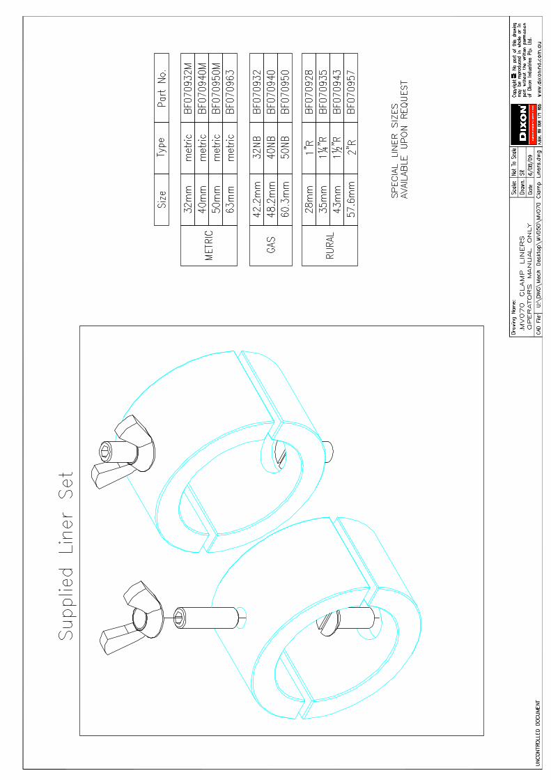
2.4. Reducing Liners for pipe ........................................................................................................... 5
2.5. Accessory Case ......................................................................................................................... 5
3. Using the MV70 ........................................................................................................................ 6
3.1. Preparation .............................................................................................................................. 6
3.2. Pipe Alignment ......................................................................................................................... 6
3.3. Facing ....................................................................................................................................... 6
3.4. Check Alignment ...................................................................................................................... 6
3.5. Bead Up .................................................................................................................................... 6
3.6. Heat Soak ................................................................................................................................. 7
3.7. Fusion Cycle .............................................................................................................................. 7
3.8. Butt Welding Table ................................................................................................................... 7
3.9. Weld Quality Check .................................................................................................................. 8
3.10. Weld failure trouble shooting .................................................................................................. 8
4. Maintenance - Daily Check List ................................................................................................ 9
5. Maintenance - periodic ............................................................................................................ 9
5.1. General ..................................................................................................................................... 9
5.2. Heater Plate ............................................................................................................................. 9
5.3. Heater Temperature Adjustment ............................................................................................. 9
5.4. Temperature Calibration .......................................................................................................... 9
5.5. Heater Non-Stick Cloth Replacement ..................................................................................... 10
5.6. Temperature Controller Failure ............................................................................................. 10
5.7. Electrical safety testing heater plate ...................................................................................... 10
5.8. Element Pad Failure ............................................................................................................... 10
5.9. Facer Drive ............................................................................................................................. 10
5.10. Cutter Blade Sharpening ........................................................................................................ 11
6. Notes About Heater Plates And Temperature ....................................................................... 12
6.1. PE Welding Temperatures ...................................................................................................... 12
6.2. Heater Plate Temperature ..................................................................................................... 12
6.3. Measuring Surface Temperature ........................................................................................... 12
7. Warranty ................................................................................................................................ 13
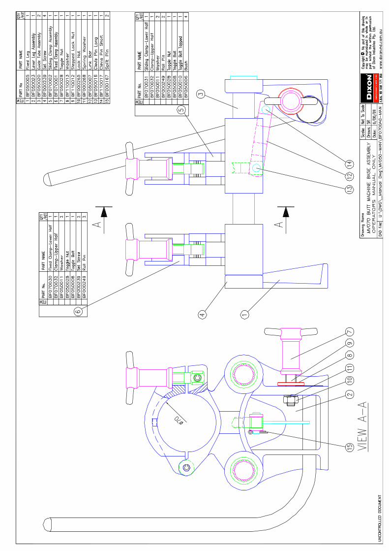
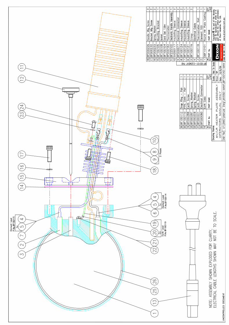
8. Machine Assembly Drawings ................................................................................................. 14

MV70 manual butt welder
Simply Better.Simply Better.Simply Better.Simply Better.
FUSIONMASTER® and DIXON® are registered trademarks of Dixon Industries Pty. Ltd. ©August 2002 Revised August 2013 page 3
1. Safety considerationsKnow the machine
Read these operating instructions carefully. Learn the operation, limitations and potential
hazards of using your butt fusion machine.
Avoid Dangerous Environments
The equipment is not explosion proof. Never carry out butt fusion in a gaseous or combustible
atmosphere.
Electrical safety
Use only a qualified electrician to carry out electrical maintenance work.
Connect electrical components only to a voltage source that corresponds to that marked on the
components.
Do not operate the electrical equipment in damp or wet locations.
Prevent electric shock by correctly grounding electrical components. The green (or green/yellow)
conductor in the electric cable is the grounding wire and should never be connected to a live
terminal. The use of earth leakage protection with portable electric tools is essential and must be
provided by the user.
Heater
The heater operates at over 200°C and contact can cause serious burns. Always wear gloves
when handling the hot plate.
The heater is supplied with a 10 amp 1.8 metre cord that has an EPR rubber outer sheath whichwill delay, but will not prevent, the inevitable life threatening situation which could occur if thecord is allowed to contact the hot plate and melt through.Never use a standard appliance cord with low melting point PVC sheath (eg. Computer cord).
Standing the hot plate so that the temperature controller handle is not vertically above the hot
plate will direct the cord away from the hot surface, and keep the controller relatively cool.
Facer
The facing machine is powerful and the cutting blades are sharp. To prevent injury the facer
should only be operated when it is securely located in the pipe cutting position.
The nature of the machine and welding process makes it impractical to guard the operational
area. Do not attempt to remove shavings from the cutting area while the facer is running.
Remove loose clothing or jewelry to prevent these items being dragged into moving parts.
Maintain Equipment Carefully
The machine has moving parts and/or parts that may deteriorate with age and require
maintenance. Regular inspection is recommended. For best results keep all machine components
clean and properly maintained. Always disconnect the power when adjusting, servicing or
changing accessories. Repair or replace damaged electric cables.
MV70 manual butt welder
Simply Better.Simply Better.Simply Better.Simply Better.
FUSIONMASTER® and DIXON® are registered trademarks of Dixon Industries Pty. Ltd. ©August 2002 Revised August 2013 page 4
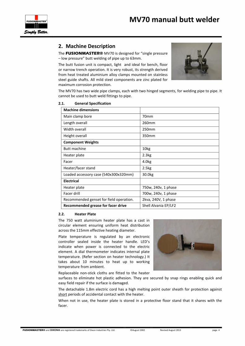
2. Machine Description
The FUSIONMASTER® MV70 is designed for “single pressure
– low pressure” butt welding of pipe up to 63mm.
The butt fusion unit is compact, light and ideal for bench, floor
or narrow trench operation. It is very robust, its strength derived
from heat treated aluminium alloy clamps mounted on stainless
steel guide shafts. All mild steel components are zinc plated for
maximum corrosion protection.
The MV70 has two wide pipe clamps, each with two hinged segments, for welding pipe to pipe. It
cannot be used to butt weld fittings to pipe.
2.1. General Specification
Machine dimensions
Main clamp bore 70mm
Length overall 260mm
Width overall 250mm
Height overall 350mm
Component Weights
Butt machine 10kg
Heater plate 2.3kg
Facer 4.0kg
Heater/facer stand 2.5kg
Loaded accessory case (540x300x320mm) 30.0kg
Electrical
Heater plate 750w, 240v, 1 phase
Facer drill 700w, 240v, 1 phase
Recommended genset for field operation. 2kva, 240V, 1 phase
Recommended grease for facer drive Shell Alvania EP/LF2
2.2. Heater Plate
The 750 watt aluminium heater plate has a cast in
circular element ensuring uniform heat distribution
across the 115mm effective heating diameter.
Plate temperature is regulated by an electronic
controller sealed inside the heater handle. LED’s
indicate when power is connected to the electric
element. A dial thermometer indicates internal plate
temperature. (Refer section on heater technology.) It
takes about 10 minutes to heat up to working
temperature from ambient.
Replaceable non-stick cloths are fitted to the heater
surfaces to eliminate hot plastic adhesion. They are secured by snap rings enabling quick and
easy field repair if the surface is damaged.
The detachable 1.8m electric cord has a high melting point outer sheath for protection against
short periods of accidental contact with the heater.
When not in use, the heater plate is stored in a protective floor stand that it shares with the
facer.

MV70 manual butt welder
Simply Better.Simply Better.Simply Better.Simply Better.
FUSIONMASTER® and DIXON® are registered trademarks of Dixon Industries Pty. Ltd. ©August 2002 Revised August 2013 page 5
2.3. Facer
The lightweight electric powered facing head is self-aligning and
will always produce parallel pipe joint faces. Operating the variable
speed motor at low speed will provide adequate torque and speed
to process small or large diameter pipes quickly. There is one blade
on each cutting face that will cut pipe from 110mm OD, to 22mm
inside diameter.
2.4. Reducing Liners for pipe
Clamp liners can be supplied to suit metric, gas or rural pipe.
The reducing liner set for each pipe size consists of 2 rings, with
each ring made up of 2 segments.
2.5. Accessory Case
A steel accessory case provides storage for the butt machine,
heater, facer, the heater/facer floor stand, and reducing liners.

MV70 manual butt welder
Simply Better.Simply Better.Simply Better.Simply Better.
FUSIONMASTER® and DIXON® are registered trademarks of Dixon Industries Pty. Ltd. ©August 2002 Revised August 2013 page 6
3. Using the MV70
3.1. Preparation
1. Connect only to a 240v, 50Hz power source. Ensure the output of any portable
generator used is 240v ±20v.
2. Clean and/or replace the non-stick cloths. Clean the heater plate before every weld
with clean dry paper or cotton cloth - never use synthetic materials that may melt.
3. Check, and if necessary adjust the heater surface temperature.
4. Install the correct reducing liners for the pipe to be welded.
5. Before facing, clean inside and outside of each pipe end, and the cutter blades.
6. Check the facer cutting action (the shaving thickness should be 0.30-0.40mm).
7. Protect the welding area from strong winds, excessive cold or heat, or rain.
8. Keep the weld zone free of bending stresses.
9. Determine the weld times required, see table 3.8.
3.2. Pipe Alignment
Place the pipes in the clamp jaws with about 20mm of pipe extending past the
clamps into the weld zone. Tighten the clamp toggle bolts securely to prevent
the pipe from slipping when force is applied. The pipe protruding outside of the
machine should be supported such that there is no external bending load on the
machine.
Move the pipe ends together until they are almost touching, then check for misalignment
(maximum allowable misalignment is 10% of wall thickness). Tolerances on small bore pipes
should be sufficient to permit pipe alignment in the MV70 without adjusting the clamps.
However, in severe out of round situations, adjust out any misalignment by loosening the clamps
and rotating the pipes, and/or using packers as necessary.
3.3. Facing
Move the pipe ends apart and place the facing machine between the pipe faces and close to the
fixed pipe. Ensure the facer body is securely hooked on to both guide shafts to ensure the facer
sits square to the frame and parallel with the clamps.
Start the facer rotating. Move the pipe ends into contact with the facer and apply just enough
force so that a continuous shaving of plastic is simultaneously produced from both sides of the
facer.
Caution: To maximise drill and facer drive life, operate the drill at low speed (for maximum
torque), and do not apply excessive force to the carriage lever.
On completion of facing, reverse the pipe carriage away from the facer then stop facer rotation.
This prevents a step being produced in the faced ends. Remove the facer and place it in the floor
stand.
3.4. Check Alignment
Clear away all plastic cuttings without contaminating the pipe ends. Do not touch the cut surface
or re-clean it. Move the pipe ends together and re-check pipe alignment (maximum allowable
misalignment is 10% of wall thickness).
Always re-face the pipe ends if it becomes necessary to rotate the pipe in the clamps after initial
facing.
3.5. Bead Up
Check the heater plate temperature before commencing each joint in case there has been any
failure of the power supply or temperature controller.
Place the heater plate between the pipe faces and close to the fixed pipe.
Caution: Ensure the heater handle does NOT stand vertically above the hot plate or dangerous
overheating may occur. Do not allow the electric cord to rest on the hot plate.
TIP
When welding
coiled and/or large
diameter pipe,
clamp the butt
machine to a solid
support base for
rigidity and to
assist with pipe
straightening and
alignment.

MV70 manual butt welder
Simply Better.Simply Better.Simply Better.Simply Better.
FUSIONMASTER® and DIXON® are registered trademarks of Dixon Industries Pty. Ltd. ©August 2002 Revised August 2013 page 7
Move the carriage to bring the pipe faces into contact with the heater plate. Maintain load until
an initial bead has formed completely around the pipe circumference on both sides of the heater
plate. The time to reach “bead up” is variable. It is greatly influenced by pipe dimensions,
ambient temperatures, and wind.
3.6. Heat Soak
After bead up, reduce the force applied to the heater and maintain just a slight positive load
between the pipe and the heater for the heat soak period. Failing to reduce pressure forces hot
plastic out of the joint zone and could lead to a weld failure.
On completion of heat soak time, reverse the carriage direction to “crack” the heater plate away
from the melted pipe, then move the heater plate out of the weld zone as quickly as possible.
(Refer to parameters table for allowable changeover time).
The unique non-stick cloths allow a "peeling off" action as the pipe is cracked away, minimising
adhesion of the melted pipe to the heater.
Remove the heater plate and replace it in the floor stand.
Caution: Do not allow the heater plate to slide across the pipe ends and distort the melted
surface. Do not contaminate the melted surface in any way.
3.7. Fusion Cycle
Bring the melted pipe faces into contact with each other immediately to minimise heat loss from
the weld zone. Build up to the required fusion force smoothly to avoid squeezing out too much
hot plastic. As the hot plastic is squeezed from the joint it rolls over to form a “bead”. Always
ensure the bead rolls back until it touches the pipe.
Shrinkage will occur as the weld cools so it is important to manually maintain force on the lever
until the bead becomes firm. Then tighten the lever wing nut to maintain load on the joint until
the weld/cooling time is complete.
3.8. Butt Welding Table
The times for butt fusion of PE80 or PE100 pipe tabled below are based on the “single pressure –
low pressure” fusion method, and assume a heater plate temperature of 220°C, ambient
temperature of 20°C, and minimal air turbulence.
Operators must allow for variations from these conditions and establish a range of times to suit
their particular environment and pipe wall thickness, paying particular attention to the size of the
bead being formed.
Pipe
Wall
Thickness
(mm)
Bead up
Time
Note (1)
Heat soak
Time
(seconds)
Note (2)
Heater
Changeover
Time
(seconds)
Note (3)
Minimum
Welding/cooling
Time
(minutes)
Note (4)
Final Bead Size
(mm)
2.0 Variable 30 3 11 4-6
5.0 Variable 75 3 13 5-8
8.0 Variable 120 3 14 7-11
Notes
(1) The time to reach “bead up” is variable. It is greatly influenced by pipe dimensions,
ambient temperatures, and wind.
(2) The heat soak period commences after the initial “bead up" i.e. after of molten material
first forms.
(3) Changeover time is the time between removal of the heater plate, and moving the
molten pipe faces together. This must be fast to prevent heat loss from the joint.
(4) The pipe should remain in the clamps under pressure for the minimum welding/cooling
time.

MV70 manual butt welder
Simply Better.Simply Better.Simply Better.Simply Better.
FUSIONMASTER® and DIXON® are registered trademarks of Dixon Industries Pty. Ltd. ©August 2002 Revised August 2013 page 8
For more information on joining PE pipe it is recommended that the following guidelines be
downloaded from Plastics Industry Pipe Association of Australia Ltd web site (www.pipa.com.au).
• POP003 Butt Fusion Jointing of PE Pipes and Fittings - Recommended Parameters.
• TP003 Specifying Butt Welding of Polyethylene Pipe Systems.
3.9. Weld Quality Check
Inspect the uniformity of the bead size and shape all around the pipe. It is advisable to monitor
and record times, temperatures and applied force at each phase of every joint for future
reference. (See section on trouble-shooting weld failures.)
3.10. Weld failure trouble shooting
(Bead shapes are exaggerated for effect.)
Uniform bead correct welding.
NB the external bead is always more uniform than the internal bead.
Crack down centre of bead.
"Cold weld" signified by clean break through the middle of the weld
with a smooth appearance.
Could be due to insufficient heat soak time or temperature, or
changeover time too long, or excessive soak pressure, or insufficient
fusion pressure, or no allowance for drag pressure, or drag pressure
too great eg due to pulling pipe up a gradient.
Misalignment - maximum allowable 10% of wall thickness.
Care should also be taken to ensure pipes or fittings being joined
have the same diameter and wall thickness or the probability of weld
failure is significantly increased.
Insufficient bead roll over.
Could be due to insufficient heat soak time or temperature, or
changeover time too long, or insufficient fusion pressure, or no
allowance for drag pressure,
Unequal bead size.
Look for temperature gradients e.g. pipe surface in the hot sun vs
pipe in the shade, or heater plate hot spots.
Look for unequal application of pressure.
If unequal uniformly around the whole circumference, look for
physical difference in materials being joined eg melt flow index.
MV70 manual butt welder
Simply Better.Simply Better.Simply Better.Simply Better.
FUSIONMASTER® and DIXON® are registered trademarks of Dixon Industries Pty. Ltd. ©August 2002 Revised August 2013 page 9
4. Maintenance - Daily Check List
1. Keep the machine and accessories clean and free of dust and grease. Do not
lubricate any MV70 components except for the facer drive (see later).
2. Check the temperature of a number of points on the surface of both sides of the
heater plate. The reading at any point on either side of the heater plate surface
should not be more than ±10°C from the desired welding temperature. (Refer later
section on heater plates.)
3. Do electrical safety checks.
4. Replace non-stick cloths if damaged in way of the weld area.
5. Facing blades should be sharp and have defect free cutting edges to provide
continuous shaving thickness of 0.30-0.40mm. Shim worn blades if necessary;
sharpen cutter blades if blunt; replace cutter blades if chipped.
6. Ensure the facer drill is securely fixed into the facer body casting, if not the drive
gears may not mesh properly causing extensive damage.
7. Feel for “sloppy” movement of the cutter plates. This indicates the need to adjust
the facer drive internally.
8. If using a portable generator, ensure its output is 240v ± 20v and 50hz, to protect
electronic equipment from permanent damage.
5. Maintenance - periodic
In addition to the daily checks, the following should be carried out before commencing each new
project, or after 250 operating hours.
5.1. General
Check the machine frame and slide rails are not bent or damaged such that sliding is restricted.
5.2. Heater Plate
Heater surfaces should be flat, smooth and free of dents or gouges. Dress as necessary.
FUSIONMASTER® heater plates have a vent machined in the edge of the casting to allow
entrapped air to escape from under the non-stick cloth. Clean out any build-up of foreign
material from the air vent to prevent any adverse temperature effect.
Caution: Ensure heater plate non-stick surfaces are protected from damage during transport.
5.3. Heater Temperature Adjustment
The temperature setting of the MV70 heater is adjusted by turning the screw in the end of the
heater handle. Turn clockwise for higher temperature, and anticlockwise for lower temperature.
One degree of turn will result in approximately one degree of temperature change. Always allow several minutes for the plate temperature to stabilise after making any adjustment. The controller is factory set to 220°C. It has an operating range of 180°C to 260°C.
5.4. Temperature Calibration
The thermometer in the heater plate indicates the internal plate temperature not the surface
temperature, although the difference will not be great.
It is essential to check and record the surface temperature of the heater plate before every weld.
This is best measured with either a contact pyrometer or a non-contact infrared pyrometer. The
outer circumference of the heater should not be measured as this is too far from the weld area.
The pyrometer used to measure surface temperature will itself require calibration to a procedure
as recommended by the pyrometer manufacturer.
Caution: Be aware that an insulating air gap can form between the Teflon cloth and the hot
plate. Always ensure the cloth is forced into contact with the hot metal surface when
using an infrared or non-contact pyrometer or a false reading is likely to occur. Never
use an infrared pyrometer on a shiny surface as a false reading will occur.

MV70 manual butt welder
Simply Better.Simply Better.Simply Better.Simply Better.
FUSIONMASTER® and DIXON® are registered trademarks of Dixon Industries Pty. Ltd. ©August 2002 Revised August 2013 page 10
5.5. Heater Non-Stick Cloth Replacement
The non-stick cloths should be replaced if they are torn, contaminated, or badly discoloured (due
to overheating) or lose their non-stick ability. Use the following procedure.
1. Use a screw driver to lever the snap rings out of their securing grooves. This takes
very little force. Do not attempt to remove the snap rings if the plate temperature is
more than 40°C because they will not release.
2. With the plate flat, place a new cloth into position and reposition the snap ring over
the cloth.
3. Push the snap ring into the groove around an arc of the plate. Hold in position with
one hand. With the free hand, use a piece of wood or plastic to force the snap ring
completely into its groove. (This may take several attempts until some experience is
developed.) Never use metallic objects to force the snap rings back into position as
this may result in accidental damage to the cloth.
5.6. Temperature Controller Failure
1. When power is connected, one LED glows amber. When the electric element is
drawing power the other LED glows red. Either of the LEDs flashing on-off indicates
the temperature controller has failed and must be replaced.
2. If neither LED glows when power is connected, first test the power supply and the
power cord to ensure those items are not at fault. If not faulty, next test the
element pad before replacing the temperature controller.
5.7. Electrical safety testing heater plate
Use an appliance tester capable of performing a Class 1 250V Run Test to verify the functionality
of FUSIONMASTER® model MV70, SV70, LF110, HF225, EHF225 heater plates. These devices
cannot be safety tested either as an earthed appliance or as a double insulated appliance
because the temperature controller Is fitted with surge protection (i.e. metal oxide varistor), and
uses solid state switching that only functions when power is applied.
5.8. Element Pad Failure
Caution: This job must be performed by a qualified electrician.
1. Disconnect the power supply.
2. (Refer to heater plate drawing.) Remove the screws securing the temperature
controller handle to the heater bracket, and the screws securing the bracket to the
heater plate.
3. Remove the bracket and gasket from the heater plate to expose the temperature
sensor probe. (If the gasket is broken by this action it should be replaced.)
4. Withdraw the sensor probe with long nose pliers, pulling on the metal case, not the
fine lead wires.
5. Disconnect the quick connect leads from the element ends and unscrew the earth
connection and measure the resistance across the two ends of the element (should
be 40 ohms ±10%). If there is a short circuit, the element pad must be replaced. If
the element, leads and connectors are OK, the controller will be faulty and must be
replaced.
6. Before re-fitting the controller, sparingly coat the sensor probe with some silicon
heat sink compound to increase thermal sensitivity, then carefully insert the probe
into the probe hole.
7. Reassemble the handle and bracket to the heater plate and tighten screws securely.
8. Reconnect the power cord and switch on. Both LEDs should glow immediately.
Allow 20 minutes for the heater to reach temperature and to stabilise before
making any adjustments or measuring temperature.
5.9. Facer Drive
Refer to Facer drawing.
1. Access the facer drive assembly by removing the securing screw from the facer
plate and removing the plate.

MV70 manual butt welder
Simply Better.Simply Better.Simply Better.Simply Better.
FUSIONMASTER® and DIXON® are registered trademarks of Dixon Industries Pty. Ltd. ©August 2002 Revised August 2013 page 11
2. Inspect the worm and worm wheel assembly for wear. If the worm, or worm wheel,
or worm shaft or dog coupling is excessively worn or broken, the complete worm
drive assembly must be replaced as a matching assembly.
3. Inspect the worm shaft needle thrust bearing for damage and replace if necessary.
4. Otherwise, clean out and re-grease sparingly with a high pressure grease e.g. Shell
Alvania EP2.
Do not use molybdenum disulphide, graphite grease or similar as these may run
and cause welding contamination.
5. Replace felt dust seals as required.
5.10. Cutter Blade Sharpening
If chipped or damaged, the blades should be replaced.
If blunt, the high grade tool steel blades may be sharpened with a die grinder. Shim the cutter
blades if they are sharp, but shavings are too thin.
MV70 manual butt welder
Simply Better.Simply Better.Simply Better.Simply Better.
FUSIONMASTER® and DIXON® are registered trademarks of Dixon Industries Pty. Ltd. ©August 2002 Revised August 2013 page 12
6. Notes About Heater Plates And Temperature
6.1. PE Welding Temperatures
Polyethylene pipe is weldable at temperatures ranging from 180°C to 260°C. However butt fusion
parameters typically specify 220 ±15°C which is the required surface temperature of the heater
plate.
Temperatures greater than 240°C when coupled with long heat soak times may result in
diminution of the anti-oxidants in the pipe.
Cold joints will result if the weld temperature is too low, or the heat soak time is too short, or the
time between removal of the heater and butting the pipes together is too long.
Caution: Either situation may lead to premature joint failure.
6.2. Heater Plate Temperature
Heater plate temperature displays generally indicate the internal heater temperature. Actual
surface temperature may vary from the display, and will also fluctuate, for the following reasons.
1. The rate of heat loss from the heater surface depends on the design of the heater
plate and temperature controller. The surface temperature could be significantly
different to the thermometer indication. This variation will be greatest on cold,
windy days. Always use a shelter when welding in these conditions.
2. As power input cycles on and off the temperature will be highest just after the
power cycles off and lowest just as it cycles back on.
3. The temperature is unlikely to be exactly the same at every point on the heater
surface due to manufacturing tolerances.
4. As heat is transferred into the pipe during heat soak, the heater temperature
initially falls but eventually returns to the set point.
6.3. Measuring Surface Temperature
5. Always wait 5 minutes after the heater has first reached set temperature for the
temperature to stabilize before recording measurements.
6. Take readings at several points (at 3, 6, 9, 12 o’clock) on both sides of the heater,
at the diameter of the pipe being welded.
7. FUSIONMASTER
heater plates are fitted with non-stick replaceable cloth. It is
essential to use a contact probe to force the cloth into intimate contact with the
plate. (Incorrect readings will result when the cloth system traps an insulating air
layer between the cloth and the heater surface.)
8. If a contact probe is used it should be held in position for several seconds before
the reading is taken.
9. If an infra red pyrometer is used incorrect reading are likely to result unless:
• the emissivity is set at 0.95 for use on the non-stick cloth;
• the device is held square to the surface being measured;
• the non-stick cloth is forced into intimate contact with the heater plate (see
suggestion below).
10. Never use an infra-red pyrometer to take a reading from a shiny aluminium
surface (such as a FUSIONMASTER
heater without cloths, or the outer rim of
a heater plate) or an error will result.
Suggestion
Use a "spot control adapter" fitted to an Infra-red pyrometer for consistently
accurate measurements. When pressed squarely against the heater surface
the infra-red beam is correctly focused every time, and intimate contact
between the heater plate and non-stick cloth is assured.
Note:
It is not physically
possible for heater
surface temperatures to
vary significantly from
one point to another. If
such a variation is
observed, it is most
likely to result from
using an incorrect
temperature measuring
technique.

MV70 manual butt welder
Simply Better.Simply Better.Simply Better.Simply Better.
FUSIONMASTER® and DIXON® are registered trademarks of Dixon Industries Pty. Ltd. ©August 2002 Revised August 2013 page 13
7. Warranty
FUSIONMASTER
Butt Fusion Equipment
1. Subject to the terms below, Dixon Industries Pty Ltd (“The Company”) warrants to
repair or replace at its option ex-works Adelaide any product manufactured or
repaired by it within 2 years from the date of shipment which are found to be
defective due to either faulty workmanship or use of faulty materials, provided
that such defective product is returned to the Company’s works at the customer’s
expense, unless otherwise agreed.
2. This warranty is limited solely to products manufactured or repaired by the
Company. Products not manufactured by the Company (such as pumps, gauges,
motors, switches, etc.) are not covered by this warranty. In relation to a repair,
this warranty is limited to the Company’s cost of parts and labour to remedy a
defective repair.
3. This warranty does not apply to any product that has been damaged by accident,
misuse, neglect, use of an electrical power supply that is incompatible with the
design specifications of the product or repair or alteration of the product by
anyone other than the Company.
4. A warranty claim must be made to the Company in writing within 14 days of the
first occurrence of the event or condition on which the claim is based. The claim
must include proof of purchase and a detailed statement of the manner in which
the product has been used and the event or condition occurred. The Company’s
decision to admit or refuse any warranty claim shall be binding.
5. Replacement parts provided to the customer before the right to a warranty claim
is accepted by the Company will be invoiced at the full cost of the parts, including
applicable taxes and freight charges. If a warranty claim is accepted, the cost of
any replacement parts covered by the warranty claim which have been so
invoiced will be credited to the customer.
6. All costs of returning product to the customer shall be paid by the customer.
7. Other than provided in this warranty, the Company excludes any other
responsibility or liability whatever to the maximum extent permitted by law
including liability for breach of contract, negligence or incidental, consequential,
indirect or special damages including without limitation, interruption to use of the
product or any other plant or equipment.
Disclaimer
As the conditions of use of welding equipment are outside the control of Dixon Industries, no
warranties are expressed or implied and no liability is assumed in connection with the use of butt
welding equipment or the butt welding guidelines or parameters.
The manufacturer reserves the right to vary specifications without notice.

A-A ( 1 : 4 )
A
A
1SH
CS 1/4BSW
x 3/4
BF000232
23
4C/Sunk SH
3/16 x 3/8
BF000217
22
1Cutter Blade, tapped
BF100212T
21
1Cutter Blade, bored
BF100212B
20
2Thrust R
ing - pair
BF100218
19
2Felt Seal - pair
BF100208
18
1SH
CS 5/16BSW
x 1 1/4
BF000253
17
1Cutter Plate - tapped
BF100202T
16
1Cutter Plate - bored
BF100202B
15
1Thrust Bearing
BF000175
14
2Thrust W
asher
BF000206
13
1Spring Pin 3/16 x 1
BF000222
12
1W
orm
W
heel
BF100224
11
1Acetal Spacer
BF100238
10
1W
orm
BF100222
9
2Spring Pin 1/8 x 3/4
BF000213
8
1W
orm
Shaft
BF100220
7
1D
og Coupling, Fixed
BF100226
6
3N
ylon Bush
BF100231
5
1D
rill, PRO
TO
OL (m
od)
BF000722
4
1D
og Coupling Threaded
BF110241G
3
1Set Screw
5/16BSW
x 5/16
BF000239
2
1Facer Body M
V/LR
BF100201
1
QT
YP
art N
am
eP
art N
o.
Ite
m
UN
CO
NTR
OLLED
D
OCU
MEN
T
Scale:
Draw
n:
Update:
05/07/13
SR
not to scale
CAD
File:
Draw
ing N
am
e:
U:\Inventor\m
v\BF100200\BF100200M
AN
.idw
A.B.N
. 89 008 171 855
ww
w.dixonind.com
.au
Copyright ©
. N
o part of this draw
ing
MV/LR Facer Assem
bly
OPER
ATO
RS M
AN
UA
L O
NLY
may be reproduced in w
hole or in
part w
ithout the w
ritten perm
ission
of D
ixon Industries Pty. Ltd.
suppl. as
kit,
Part N
o.
BF100212
Worm
&
Coupling
Assem
bly,
Kit Part
No.
BF100205
Facer W
orm
D
rive Assem
bly, Part N
o. BF100204
Drill/Coupling PR
OTO
OL
Part N
o. BF110240
fro
m 0
1/1
2/2
00
9
34
86
7
10
89
12
11
5
23
22
21
16
19
18
5
15
20
22
2
1
5
13
14
13

1Thrust Bearing
BF000175
10
2Thrust W
asher
BF000206
9
1Spring Pin
BF000222
8
1W
orm
W
heel
BF100224
7
1Acetal Spacer
BF100238
6
1W
orm
BF100222
5
2Spring Pin
BF000213
4
1W
orm
Shaft
BF100220
3
1D
og Coupling, Fixed
BF100226
2
3N
ylon Bush
BF100231
1
QT
YP
art N
am
eP
art N
o.
Ite
m
UN
CO
NTR
OLLED
D
OCU
MEN
T
Scale:
Draw
n:
Update:
05/07/13
SR
not to scale
CAD
File:
Draw
ing N
am
e:
U:\Inventor\m
v\BF100200\BF100200M
AN
.idw
A.B.N
. 89 008 171 855
ww
w.dixonind.com
.au
Copyright ©
. N
o part of this draw
ing
MV/LR
/LF Facer W
orm
D
rive Assem
bly
OPER
ATO
RS M
AN
UA
L O
NLY
may be reproduced in w
hole or in
part w
ithout the w
ritten perm
ission
of D
ixon Industries Pty. Ltd.
- Item
2, 3 &
5 to be drilled in one setup.
- Pin Item
2 &
3 before assem
bly into Facer Body.
- Pin Item
5 to pre-drilled hole of Item
3
on Facer Body Assem
bly.
BF100205 W
orm
&
Coupling Assem
bly
Note O
rientation
BF100204
Facer Worm Drive Assembly
42
34
5
11
68
79
10
9

DIXON INDUSTRIES PTY LTDABN 89 008 171 855
17 Frederick Road, Royal ParkSouth Australia, 5014.
Tel: (08) 8240 1555Fax: (08) 8240 5588