mV and mA Simulator, for pH and ORP - prominent.com · mV and mA Simulator for pH and ORP Operating...
16
mV and mA Simulator for pH and ORP Operating manual A2255 EN Target group: Commercial use! 983644 BA DMZ 011 04/16 EN Please carefully read these operating instructions before use. · Do not discard. The operator shall be liable for any damage caused by installation or operating errors. The latest version of the operating instructions are available on our homepage.
Transcript of mV and mA Simulator, for pH and ORP - prominent.com · mV and mA Simulator for pH and ORP Operating...
mV and mA Simulatorfor pH and ORP
Operating manual
A2255
EN
Target group: Commercial use!983644 BA DMZ 011 04/16 EN
Please carefully read these operating instructions before use. · Do not discard.The operator shall be liable for any damage caused by installation or operating errors.
The latest version of the operating instructions are available on our homepage.
General non-discriminatory approach In order to make it easier to read, this docu‐ment uses the male form in grammatical struc‐tures but with an implied neutral sense. It isaimed equally at both men and women. Wekindly ask female readers for their under‐standing in this simplification of the text.
Supplementary information
Please read the supplementary information in its entirety.
Information
This provides important information relating to the correct operation of the unit or is intended tomake your work easier.
Safety Information
The safety notes include detailed descriptions of the hazardous situation.
The following symbols are used to highlight instructions, links, lists, results and other elements inthis document:
More symbols
Symbol Description
Action, step by step
⇨ Outcome of an action
Links to elements or sections of these instructions or other applicable docu‐ments
n List without set order
[Taster] Display element (e.g. indicators)
Operating element (e.g. button, switch)
‘Display /GUI’ Screen elements (e.g. buttons, assignment of function keys)
CODE Presentation of software elements and/or texts
Supplemental instructions
2

Table of contents1 General Information on the Product........................................................................................ 4
1.1 Specifications................................................................................................................. 5
2 Safety, Storage and Transport................................................................................................ 72.1 Safety............................................................................................................................. 72.2 Storage and Transport................................................................................................... 7
3 Operation................................................................................................................................ 83.1 Simulation of actively driven mA current........................................................................ 93.2 Simulating a Passive Current (Current Loop) .............................................................. 103.3 Simulating mV Voltage for pH and ORP...................................................................... 11
4 Technical Data...................................................................................................................... 13
5 Disposal of Used Parts.......................................................................................................... 14
Table of contents
3

1 General Information on the ProductmV/mA simulator in a transport box. Completewith connecting lines for D1Cb, DACa, DCCaand other controllers.
Order number: 1059295
Features
The mV/mA simulator is a source and meas‐uring tool. The simulator can be used as ameasuring device or output for 0 ... 24 mA of aDC current loop or 0 ... 10 V DC voltage.
The simulator can measure the DC current loopwith very high precision of 0.015 % and 1 uAresolution.
The simulator can simulate the voltage outputof process signals of a control.
The simulator can simulate source or 24 mAloop current.
The simulator can provide 100 mV or 10 Vsource voltage.
The simulator can provide 24 V loop powerwhilst simultaneously measuring current.
General Information on the Product
4

Parameter: measuring and output voltage
mV parameter
Function Range Resolution
DC V mV input 0 ... 100 mV 0.01 mV
0 ... 10 V 0.001 V
DC V mV output 0 ... 100 mV 0.01 mV
0 ... 10 V 0.001 V
Loop output line 24 V DC ---
mA parameter
Function Range Resolution
DC mA input 0 ... 24 mA 0.001 mA
DC mA output 0 ... 24 mA 0.001 mA
1.1 SpecificationsThe specification is based on a one-year calibration cycle and applies between + 18 °C ... + 28 °C,unless otherwise stated.
DC V input and output
Range Resolution Precision
100 mV 0.01 mV ± 0.02 %
10 V 0.001 V ± 0.02 %
Input resistance 2 ㏁ (nominal), < 100 pF
Overvoltage protection 30 V
Voltage drivability 1 mA
General Information on the Product
5
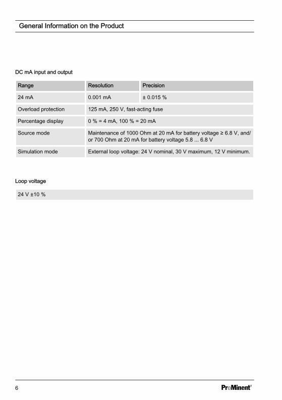
DC mA input and output
Range Resolution Precision
24 mA 0.001 mA ± 0.015 %
Overload protection 125 mA, 250 V, fast-acting fuse
Percentage display 0 % = 4 mA, 100 % = 20 mA
Source mode Maintenance of 1000 Ohm at 20 mA for battery voltage ≥ 6.8 V, and/or 700 Ohm at 20 mA for battery voltage 5.8 ... 6.8 V
Simulation mode External loop voltage: 24 V nominal, 30 V maximum, 12 V minimum.
Loop voltage
24 V ±10 %
General Information on the Product
6
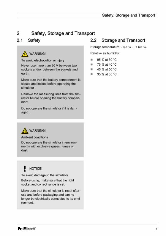
2 Safety, Storage and Transport2.1 Safety
WARNING!
To avoid electrocution or injuryNever use more than 30 V between twosockets and/or between the sockets andearth.
Make sure that the battery compartment isclosed and locked before operating thesimulator
Remove the measuring lines from the sim‐ulator before opening the battery compart‐ment.
Do not operate the simulator if it is dam‐aged.
WARNING!
Ambient conditionsDo not operate the simulator in environ‐ments with explosive gases, fumes ordust.
NOTICE!
To avoid damage to the simulatorBefore using, make sure that the rightsocket and correct range is set.
Make sure that the simulator is reset afteruse and before packaging and can nolonger be electrically connected to its envi‐ronment.
2.2 Storage and TransportStorage temperature: - 40 °C ... + 60 °C.
Relative air humidity:
n 95 % at 30 °Cn 75 % at 40 °Cn 45 % at 50 °Cn 35 % at 55 °C
Safety, Storage and Transport
7

3 Operation
A2256
mVDCmA%
INPUT-+ 1
11
109 8
7
6
5
4
32
1716
1514
13
12
18
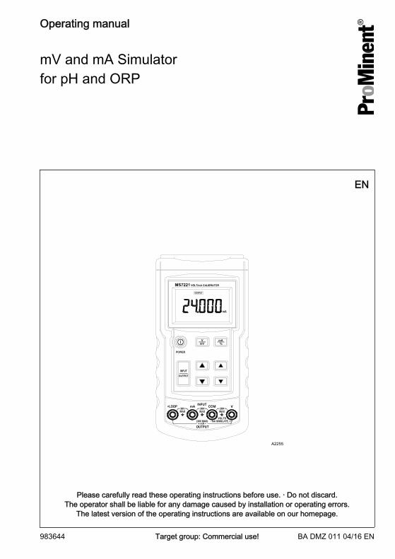
Fig. 1: Operation
1 Output2 mV mode3 mA mode4 mA mode key5 Increases the value after the point6 Lowers the value after the point7 Input, COM8 Output, Volt9 Input, mA
10 Output, loop [+Loop]11 Lowers the value before the point12 Changeover switch, input/output13 Increases the value before the point14 Switch on key15 mV mode key16 Display of the result17 Battery warning18 Input
Operation
8
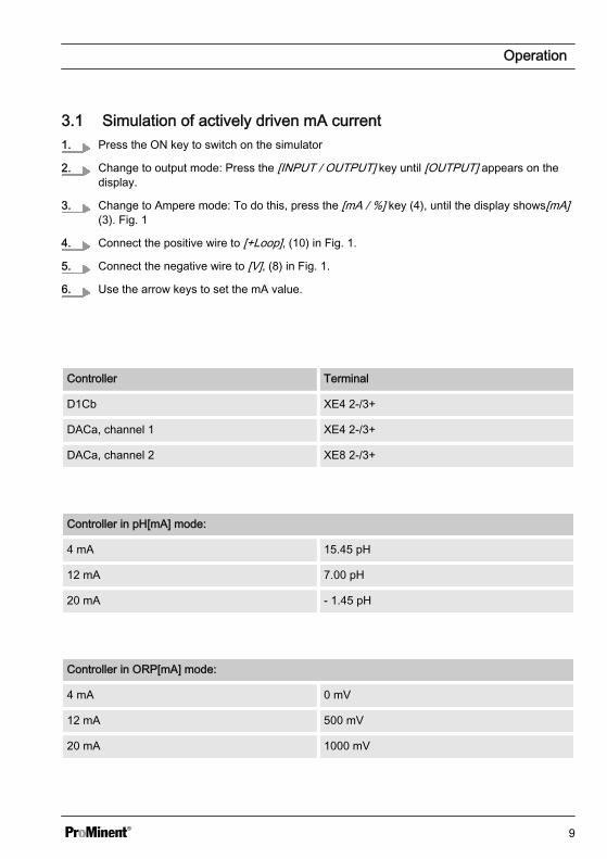
3.1 Simulation of actively driven mA current1. Press the ON key to switch on the simulator
2. Change to output mode: Press the [INPUT / OUTPUT] key until [OUTPUT] appears on thedisplay.
3. Change to Ampere mode: To do this, press the [mA / %] key (4), until the display shows[mA](3). Fig. 1
4. Connect the positive wire to [+Loop], (10) in Fig. 1.
5. Connect the negative wire to [V], (8) in Fig. 1.
6. Use the arrow keys to set the mA value.
Controller Terminal
D1Cb XE4 2-/3+
DACa, channel 1 XE4 2-/3+
DACa, channel 2 XE8 2-/3+
Controller in pH[mA] mode:
4 mA 15.45 pH
12 mA 7.00 pH
20 mA - 1.45 pH
Controller in ORP[mA] mode:
4 mA 0 mV
12 mA 500 mV
20 mA 1000 mV
Operation
9
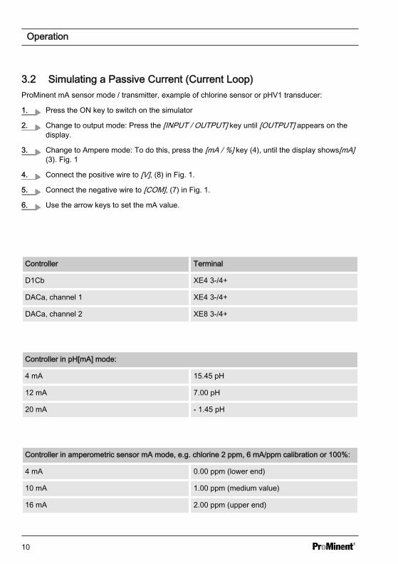
3.2 Simulating a Passive Current (Current Loop)ProMinent mA sensor mode / transmitter, example of chlorine sensor or pHV1 transducer:
1. Press the ON key to switch on the simulator
2. Change to output mode: Press the [INPUT / OUTPUT] key until [OUTPUT] appears on thedisplay.
3. Change to Ampere mode: To do this, press the [mA / %] key (4), until the display shows[mA](3). Fig. 1
4. Connect the positive wire to [V], (8) in Fig. 1.
5. Connect the negative wire to [COM], (7) in Fig. 1.
6. Use the arrow keys to set the mA value.
Controller Terminal
D1Cb XE4 3-/4+
DACa, channel 1 XE4 3-/4+
DACa, channel 2 XE8 3-/4+
Controller in pH[mA] mode:
4 mA 15.45 pH
12 mA 7.00 pH
20 mA - 1.45 pH
Controller in amperometric sensor mA mode, e.g. chlorine 2 ppm, 6 mA/ppm calibration or 100%:
4 mA 0.00 ppm (lower end)
10 mA 1.00 ppm (medium value)
16 mA 2.00 ppm (upper end)
Operation
10

3.3 Simulating mV Voltage for pH and ORPProMinent mA sensor mode / transmitter, example of chlorine sensor or pHV1 transducer:
1. Press the ON key to switch on the simulator
2. Change to output mode: Press the [INPUT / OUTPUT] key until [OUTPUT] appears on thedisplay.
3. Change to Volt mode: To do this, press the [V / mV] key (15), until the display shows[V] (2). Fig. 1
4. Only use the right arrow keys (5 and 6) in Fig. 1, to set the V value between 0.000 and 0.500mV.
Controller with mV input:
5. Connect: For positive ORP voltages and pH 7.00 ... 2.00: Plus pole to the V input (8), Minuspole to the COM input (7), see Fig. 1.
6. Connect: For negative ORP voltages and pH values of 7.00 ... 14.00: Plus pole to the COMinput (7), Minus pole to the V input (8), see Fig. 1.
Controller Terminal
D1Cb XE1/XE2
DACa, channel 1 XE1/XE2
DACa, channel 2 XE5/XE6
pH assignment to mV
pH mV
0.00 414
1.00 355
2.00 296
3.00 237
4.00 177
Operation
11
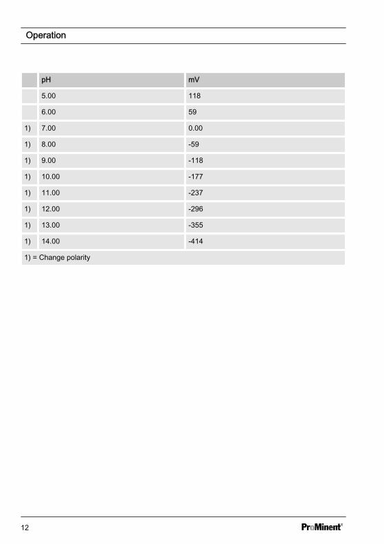
pH mV
5.00 118
6.00 59
1) 7.00 0.00
1) 8.00 -59
1) 9.00 -118
1) 10.00 -177
1) 11.00 -237
1) 12.00 -296
1) 13.00 -355
1) 14.00 -414
1) = Change polarity
Operation
12
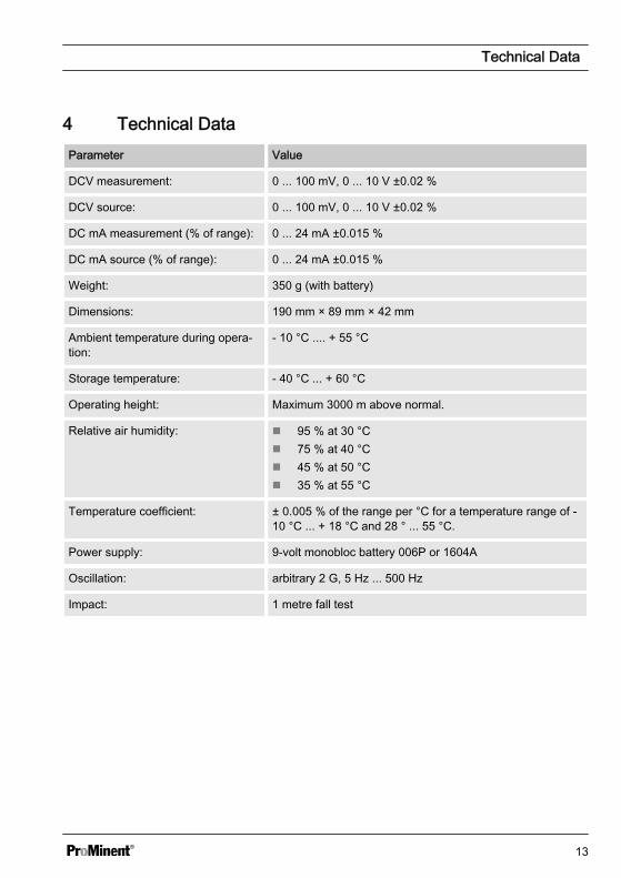
4 Technical DataParameter Value
DCV measurement: 0 ... 100 mV, 0 ... 10 V ±0.02 %
DCV source: 0 ... 100 mV, 0 ... 10 V ±0.02 %
DC mA measurement (% of range): 0 ... 24 mA ±0.015 %
DC mA source (% of range): 0 ... 24 mA ±0.015 %
Weight: 350 g (with battery)
Dimensions: 190 mm × 89 mm × 42 mm
Ambient temperature during opera‐tion:
- 10 °C .... + 55 °C
Storage temperature: - 40 °C ... + 60 °C
Operating height: Maximum 3000 m above normal.
Relative air humidity: n 95 % at 30 °Cn 75 % at 40 °Cn 45 % at 50 °Cn 35 % at 55 °C
Temperature coefficient: ± 0.005 % of the range per °C for a temperature range of -10 °C ... + 18 °C and 28 ° ... 55 °C.
Power supply: 9-volt monobloc battery 006P or 1604A
Oscillation: arbitrary 2 G, 5 Hz ... 500 Hz
Impact: 1 metre fall test
Technical Data
13

5 Disposal of Used Partsn User qualification: instructed user.
NOTICE!
Regulations governing the disposal ofused parts– Note the national regulations and
legal standards that currently apply inyour country
The manufacturer will take back decontami‐nated used units providing they are covered byadequate postage.
Decontaminate the unit before returning it forrepair. To do so, remove all traces of haz‐ardous substances.
A current Declaration of Decontamination isavailable to download on the ProMinent web‐site.
Disposal of Used Parts
14

15
983644, 1, en_GB
© 2016
ProMinent GmbHIm Schuhmachergewann 5 - 1169123 Heidelberg, GermanyTelephone: +49 (6221) 842-0Fax: +49 (6221) 842-419Email: [email protected]: www.prominent.com