MUZAFFARPUR INSTITUTE OF TECHNOLOGY · Name of the experiment Date Page no Remarks 01 Stability of...
22
` MUZAFFARPUR INSTITUTE OF TECHNOLOGY Muzaffarpur LAB MANUAL Branch: Civil Engineering Year & Semester: 2 nd Year/ 3 rd Sem FLUID MECHANICS LABORATORY (01 1X07) Prepared By: Niraj Kumar Atul Kumar Rahul Assistant Professor Assistant Professor Department of Civil Engineering Department of Civil Engineering
Transcript of MUZAFFARPUR INSTITUTE OF TECHNOLOGY · Name of the experiment Date Page no Remarks 01 Stability of...

`
MUZAFFARPUR INSTITUTE OF TECHNOLOGY
Muzaffarpur
LAB MANUAL
Branch: Civil Engineering
Year & Semester: 2nd
Year/ 3rd
Sem
FLUID MECHANICS LABORATORY
(01 1X07)
Prepared By:
Niraj Kumar Atul Kumar Rahul
Assistant Professor Assistant Professor
Department of Civil Engineering Department of Civil Engineering

`
FLUID MECHANICS LABORATORY
(01 1X07 P)
INDEX
Sl.
No. Name of the experiment Date Page no Remarks
01 Stability of floating bodies
02 Flow through notches
03 To verify Bernoulli’s theorem
04 Impact of jet
05 Coefficient of discharge, contraction &
velocity of an Orifice
06 Determination of Reynolds number

`
Experiment No: 1 Date:
Title: Stability of Floating Bodies
Aim:- To determine the Meta-centric height of a floating body.
Apparatus Used:- Take tank 2/3 full of water, floating vessel or pontoon fitted with a pointed
pointer moving on a graduated scale, with weights adjusted on a horizontal beam.
Theory: -
Consider a floating body which is partially immersed in the liquid, when such a body is tilted,
the center of buoyancy shifts from its original position ‘B’ to ‘B’ (The point of application of
buoyanant force or upward force is known as center of G which may be below or above the
center of buoyancy remain same and couple acts on the body. Due to this couple the body
remains stable. At rest both the points G and B also Fb x Wc act through the same vertical line
but in opposite direction. For small change (θ) B shifted to B.
The point of intersection M of original vertical line through B and G with the new vertical, line
passing through ‘B’ is known as metacentre. The dis tance between G and M is known as
metacentre height which is measure of static stability.

`
Formula Used:-
Where: -
Wm is unbalanced mass or weight.
Wc is weight of pontoon or anybody.
Xd is the distance from the center of pointer to striper or unbalanced weight.
θ is angle of tilt or heel.
Procedure: -
1. Note down the dimensions of the collecting tank, mass density of water.
2. Note down the water level when pontoon is outside the tank.
3. Note down the water level when pontoon is inside the tank and their difference.
4. Fix the strips at equal distance from the center.
5. Put the weight on one of the hanger which gives the unbalanced mass.
6. Take the reading of the distance from center and angle made by pointer on arc.
7. The procedure can be repeated for other positioned and values of unbalanced mass.
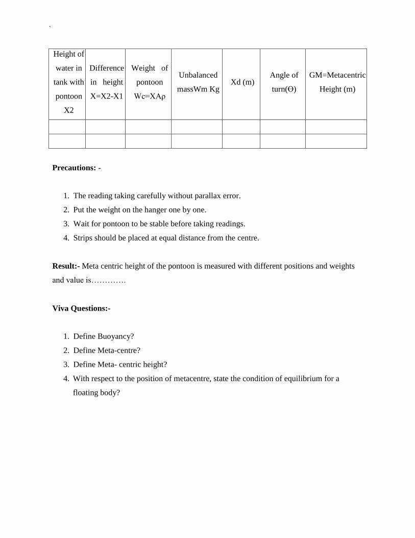
Observation Table:-
Length of the tank =
Width of the tank =
Area of the tank =
Initial level of the water without pontoon X1 =
Final level of the water with pontoon (after adding unbalanced weight) X2 =
Difference in height of water (X) = X2–X1=
`
Height of
water in
tank with
pontoon
X2
Difference
in height
X=X2-X1
Weight of
pontoon
Wc=XAρ
Unbalanced
massWm Kg Xd (m)
Angle of
turn(Ɵ)
GM=Metacentric
Height (m)
Precautions: -
1. The reading taking carefully without parallax error.
2. Put the weight on the hanger one by one.
3. Wait for pontoon to be stable before taking readings.
4. Strips should be placed at equal distance from the centre.
Result:- Meta centric height of the pontoon is measured with different positions and weights
and value is………….
Viva Questions:-
1. Define Buoyancy?
2. Define Meta-centre?
3. Define Meta- centric height?
4. With respect to the position of metacentre, state the condition of equilibrium for a
floating body?
`
Experiment No: 2 Date:
Title: Flow through notches
Aim: - To determine the coefficient of discharge of V- Notch
Apparatus Used:- Arrangement for finding the coefficient of discharge inclusive of supply tank,
collecting tank, pointer, scale & different type of notches
Theory:- Notches are overflow structure where length of crest along the flow of water is
accurately shaped to calculate discharge.
Formula Used:-
For V notch the discharge:
Actual discharge Qa =AY/t m3/s
Theoretical discharge Qt =8/15√2g. tanθ/2 H5/2
m3/s
Co efficient of discharge Cd = Q actual / Q theoretical
Where:-
Q = Discharge
H =Height above crest level
θ= Angle of notch
B = Width of notch

`
Procedure:-
1. The notch under test is positioned at the end of tank with vertical sharp edge on the
upstream side.
2. Open the inlet valve and fill water until the crest of notch.
3. Note down the height of crest level by pointer gauge.
4. Change the inlet supply and note the height of this level in the tank.
5. Note the volume of water collected in collecting tank for a particular time and find out
the discharge.
6. Height and discharge readings for different flow rate are noted.
Observations:-
Breath of tank =
Length of tank =
Height of water to crest level for V notch =
Angle of V notch =
Discharge Calculation Head
Initial
height of
tank
(Y1)
Final
height of
tank
(Y2)
Difference
in height
(Y2- Y1)
Volume
(V)
Time
(t)
Q =
(V/t)
Height of
water to
crest level
for V
notch
(H1)
Final
height
reading
above
crest (H2)
Head above
crest level
H= (H2- H1)
Cd

`
Precaution:-
1. Make the water level surface still, before takings the reading.
2. Reading noted should be free from parallax error.
3. The time of discharge is noted carefully.
4. Only the internal dimensions of collecting tank should be taken for consideration and
calculations.
Result:
The value of Cd for V-Notch……
Viva Questions:-
1. Differentiate between :-
Uniform and non-
uniform flow Steady
and unsteady flow
2. Define notch?
3. What is coefficient of discharge?

`
Experiment No: 3 Date:
Title: Verify the Bernoulli’s Theorem
Aim:- To verify the Bernoulli’s theorem.
Apparatus Used:- A supply tank of water, a tapered inclined pipe fitted with no. of
piezometer tubes point, measuring tank, scale, stop watch.
Theory:- Bernoulli’s theorem states that when there is a continues connection between the
particle of flowing mass liquid, the total energy of any sector of flow will remain same provided
there is no reduction or addition at any point.

`
Formula Used:-
H = Total Head
Z= Potential head
P/ g = Pressure head
V2/2g =Velocity head
P = intensity of pressure
S = density of water
g = acceleration due to gravity
V = velocity of flowing water
H1 = H2 = H3 = H (Total Head)
Procedure:-
1. Open the inlet valve slowly and allow the water to flow from the supply tank.
2. Now adjust the flow to get a constant head in the supply tank to make flow in and out
flow equal.
3. Under this condition the pressure head will become constant in the piezometer tubes.
4. Note down the quantity of water collected in the measuring tank for a given interval of
time.
5. Compute the area of cross-section under the piezometer tube.
6. Compute the area of cross-section under the tube.
7. Change the inlet and outlet supply and note the reading.
8. Take at least three readings as described in the above steps.

`
Observation table:-
1 2 3 4 5 6 7 8 9 10 11
Reading of
piezometric tubes
Area of cross
section under the
foot of each point
Velocity of water
under foot of each
point
V2/2g
p/ρ
V2/2g + p/ρ
Sample calculation:
Dimensions of measuring tank
L = and B =
Area of measuring tank, (A) = (L×B)=
Rise in water level in the measuring tank, (x)=
Time taken for the water rise in the tank (t) =
Actual Discharge (Q) =
Area of cross section of the duct (a) =
velocity (v) = Q/a
velocity head = V2/2g (g = 9.81m/s)

`
Precautions:-
1. When fluid is flowing, there is a fluctuation inthe height of piezometer tubes, note the
mean position carefully.
2. Carefully keep some level of fluid in inlet and outlet supply tank.
Result:-
Viva Questions:-
1. Briefly explain the various terms involved in Bernoulli’s equation?
2. Assumption made to get Bernoulli’s equation from Euler’s equation by made?

`
Experiment No: 4 Date:
Title: Impact of jet
Aim: - To determine the co efficient of impact for vanes.
Apparatus Used:- Collecting tank, Transparent cylinder, Two nozzles of dia 10 mm & 12mm,
Vane of different shape (flat, inclined or curved)
Theory:- Momentum equation is based on Newton’s second law of motion which states that the
algebraic sum of external forces applied to control volume of fluid in any direction is equal to the
rate of change of momentum in that direction. The external forces include the component of the
weight of the fluid & of the forces exerted externally upon the boundary surface of the control
volume. If a vertical water jet moving with velocity is made to strike a target, which is free to
move in the vertical direction then a force will be exerted on the target by the impact of jet,
according to momentum equation this force (which is also equal to the force required to bring
back the target in its original position) must be equal to the rate of change of momentum of the
jet flow in that direction.
Figure: Impact of jet

`
Formula Used:-
F = ρQ V(1-cosβ)
F' = ρQ2 (1-cosβ)
Where F' =force (calculated)
ρ= density of water
β=angle of difference vane
V =velocity of jet angle
Q =discharge
A =area of nozzle ( π/4d2)
For flat vane:
Β = 90o
F = ρQ2/a
Procedure:-
1. Note down the relevant dimension or area of collecting tank, dia of nozzle, and
density of water.
2. Install any type of vane i.e. flat, inclined or curved.
3. Install any size of nozzle i.e. 10mm or 12mm dia.
4. Note down the position of upper disk, when jet is not running.
5. Note down the reading of height of water in the collecting tank.
6. As the jet strike the vane, position of upper disk is changed, note the reading in the scale
to which vane is raised.
7. Put the weight of various values one by one to bring the vane to its initial position.
8. At this position finds out the discharge also.
9. The procedure is repeated for each value of flowrate by reducing the water supply.

`
10. This procedure can be repeated for different type of vanes and nozzle.
Observation table:-
Dia of nozzle =
Mass density of water ρ=
Area of collecting tank =
Area of nozzle =
Horizontal flat vane:
When jet is not running, position of upper disk is at=
Sr. Discharge measurement
Balancin
g Theoretical Error in%
No. Initial Final Time Discharge Mass Force force =(F-F’)/F’
(cm.) (cm.) (sec) Q (cm3/sec) (gm) F(dyne) F’= ρQ
2/a
1.
2.
3.
Result:
Precautions:-
1. Water flow should be steady and uniform.
2. The reading on the scale should be taken withoutany error.
3. The weight should be put slowly & one by one.
4. After changing the vane the flask should be closed tightly.
Viva Questions:-
1. Define the terms impact of jet and jet propulsion?
2. Find the expression for efficiency of a series of moving curved vane when a jet of water
strikes the vanes at one of its tips?

`
Experiment No: 5 Date:
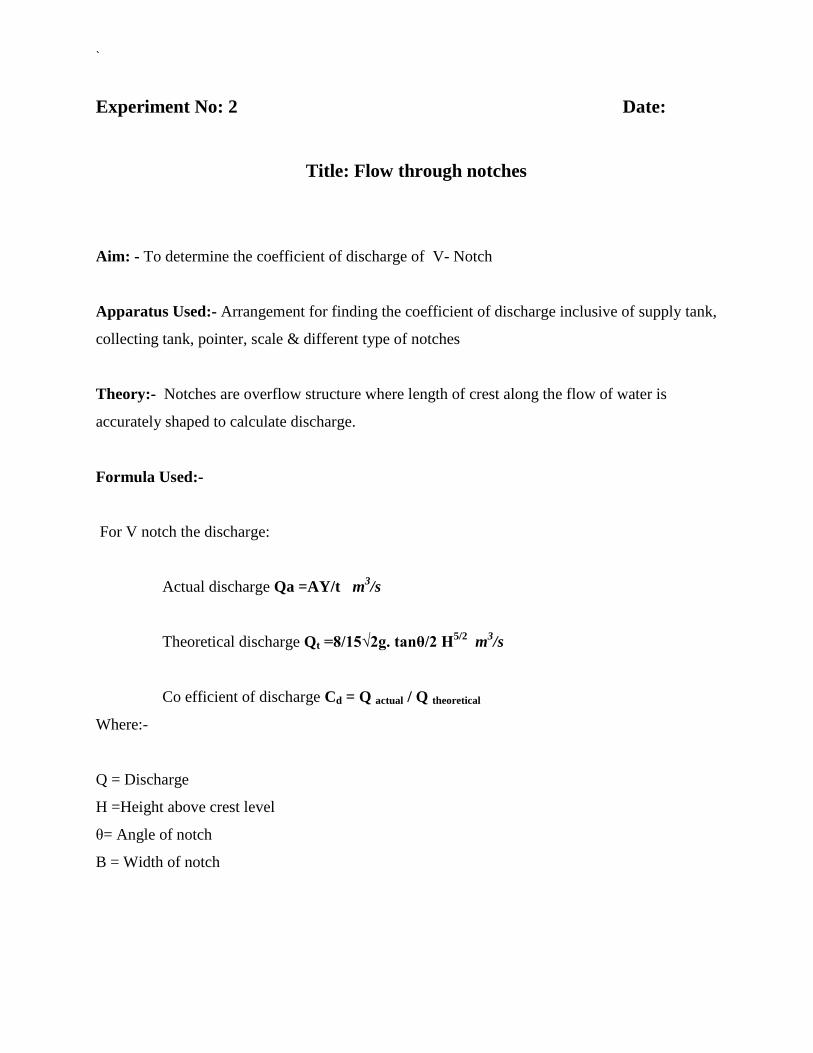
Title: Coefficient of discharge, contraction & velocity of an Orifice
Aim:- To determine the coefficient of discharge, contraction & velocity of an Orifice.
Apparatus Used:- Supply tank with overflow arrangement, Orifice plate of different diameter,
hook gauge, collecting tank, piezometric tube.
Theory:- A mouthpiece is a short length of pipe which is two or three times its diameter in
length. If there pipe is filled externally to the orifices, the mouthpiece is called external
cylindrical mouthpiece and discharge through orifice increase is a small opening of any cross-
section on the side of bottom of the tank, through which the fluid is flowing orifice coefficient of
velocity is defined as the ratio of two actual discharge to orifice ratio of the actual velocity of the
jet at vena- contracta to the coefficient of theoretical velocity of the jet coefficient of contraction
of defined as ratio of the actual velocity of jet at vena- contracta.
Vena- Contracta:- The fluid out is in form of jet goes on contracting form orifice up todispute
of about ½ the orifice dia. After the expend this least relation
Coefficient of velocity:- It is a ratio of actual velocity jet at vena-contracta to theoretical
velocity.
Formula Used:-
√
`
Fig: Flow through Orifice

`
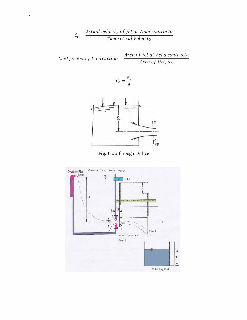
Procedure:-
1. Set the mouthpiece of orifice of which the Cc, Cu, Cd are to be determined.
2. Note the initial height of water in the steady flow tank and the height of datum from the
bottom of orifice and mouthpiece. These remains constant for a particular mouthpiece or
orifice.
3. By using the stop valve, set a particular flow in tank and tank height of water in tank.
4. Take the reading of discharge on this particular flow.
5. Using hook gauge, find the volume of Xo Y for mouthpiece.
6. Take three readings using hook gauge for one particular orifice.
7. Using the formula get value of Cd, Cu, and Cc for a particular orifice and
mouthpiece.
Observation:-
Area of measuring tank =
Dia. Of orifice d =
Area of Orifice =
Discharge Calculation:
Sl. No.
Tank Reading
Discharge(Q=Ah/t) Initial
height h1
Final height
h2 h=h2-h1 Time (t)

`
Co-efficient Calculation:
Head
(H)
X- axis Y- axis
Qth =
√
Cd=
Qact/Qth
Cv=
√
Cc=
Cd/Cv X1 X2
X=
X2-
X1
Y1 Y2 Y=Y2
-Y1
Result:-
Precautions:-
1. Take the reading of discharge accurately.
2. Take value of h without any parallax error.
3. Set the orifice and mouthpiece.
4. Height of water in the steady flow.
5. Take reading from hook gauge carefully

`
Experiment No: 6 Date:
Title: Determination of Reynolds number
Aim : To determine the Reynolds no with hele shaw apparatus
Apparatus Used: hele shaw Instrument, Measuring Cylinder, KMnO4 Solution, Cylinder
Container
Theory: This experiment employs the Hele shaw setup which produces a Flow pattern similar to
that of potential flow. The flow is actually a highly viscous flow between two parallel plates with
a very small gap between them. The flow through this apparatus is 2-D, low-speed. Although the
flow is at low Reynolds number, this has a wide application in the Flow visualization apparatus
as it produces the streamlines of potential flow.
Fig: Hele Shaw Apparatus

`
Formula Used:-
Q=
Q= Discharge
A= Cross-section Area of Measuring Cylinder
H= Difference in height
V =
V= Velocity
Q= Discharge
A= Area of the flow passage between the parallel plates from the tank (Area of slit)
Reynolds number (Re)
= Mass density of fluid
V = Velocity
L = Characteristic Linear dimension
=
Procedure:
1. Mount the Hele-Shaw apparatus in a vertical position.
2. Place the model at the middle of the test section
3. Start the flow around the model
4. Time taken to fill the height of the measuring beaker shall be noted to calculate the
volumetric flow rate
5. Photograph the flow

`
6. Change the angle of attack and visualize the change in flow features
7. Visualize the flow patterns for different models
8. Calculate Reynolds number
Observation table for Circular plate
Sl. No. Height Time(t) Discharge
(m3/s)
Area
(m2)
Velocity(m/s) Chord
Length
(m)
Re
1.
2.
3.
Observation table for Rectangular plate
Sl. No. Height Time(t) Discharge
(m3/s)
Area
(m2)
Velocity(m/s) Chord
Length
(m)
Re
1.
2.
3.
Result: Reynolds number for rectangular and circular plate is---------------------------------