Musician’s Guide for the SP4-7, SP4-8, and SP76-II · Kurzweil ® is a product line of Young...
118
i Musician’s Guide for the SP4-7, SP4-8, and SP76-II ©2010 All rights reserved. Kurzweil ® is a product line of Young Chang Co., Ltd. Young Chang®, Kurzweil ®, V. A. S. T. ®, PC3®, KDFX®, Pitcher®, and LaserVerb®, KSP8 ™, K2661™, K2600™, K2500™, and K2000™ are trademarks of Young Chang Co., Ltd. All other products and brand names are trademarks or registered trademarks of their respective companies. Prod- uct features and specifications are subject to change without notice. You may legally print up to two (2) copies of this document for personal use. Commercial use of any copies of this document is prohibited. Young Chang Co. retains ownership of all intellectual property represented by this document. ® Part Number 910529 Rev. A
Transcript of Musician’s Guide for the SP4-7, SP4-8, and SP76-II · Kurzweil ® is a product line of Young...

i
Musician’s Guidefor the SP4-7, SP4-8, and SP76-II
©2010 All rights reserved. Kurzweil ® is a product line of Young Chang Co., Ltd. Young Chang®, Kurzweil ®, V. A. S. T. ®, PC3®, KDFX®, Pitcher®, and LaserVerb®, KSP8 ™, K2661™, K2600™, K2500™, and K2000™ are trademarks of Young Chang Co., Ltd. All other products and brand names are trademarks or registered trademarks of their respective companies. Prod-uct features and specifications are subject to change without notice.
You may legally print up to two (2) copies of this document for personal use. Commercial use of any copies of this document is prohibited. Young Chang Co. retains ownership of all intellectual property represented by this document.
®
Part Number 910529 Rev. A
ii
ii
IMPORTANT SAFETY & INSTALLATION INSTRUCTIONS
INSTRUCTIONS PERTAINING TO THE RISK OF FIRE, ELECTRIC SHOCK, OR INJURY TO PERSONS
WARNING:
When using electric products, basic precautions shouldalways be followed, including the following:1. Read all of the Safety and Installation Instructions and Explanation
of Graphic Symbols before using the product.2. This product must be grounded. If it should malfunction or break
down, grounding provides a path of least resistance for electriccurrent to reduce the risk of electric shock. This product is equippedwith a power supply cord having an equipment-groundingconductor and a grounding plug. The plug must be plugged into anappropriate outlet which is properly installed and grounded inaccordance with all local codes and ordinances.
DANGER:
Improper connection of the equipment-groundingconductor can result in a risk of electric shock. Do not modify theplug provided with the product - if it will not fit the outlet, have aproper outlet installed by a qualified electrician. Do not use anadaptor which defeats the function of the equipment-groundingconductor. If you are in doubt as to whether the product is properlygrounded, check with a qualified serviceman or electrician.
3.
WARNING:
This product is equipped with an AC input voltageselector. The voltage selector has been factory set for the mainssupply voltage in the country where this unit was sold. Changingthe voltage selector may require the use of a different power supplycord or attachment plug, or both. To reduce the risk of fire or electricshock, refer servicing to qualified maintenance personnel.
4. Do not use this product near water - for example, near a bathtub,washbowl, kitchen sink, in a wet basement, or near a swimmingpool, or the like.
5. This product should only be used with a stand or cart that isrecommended by the manufacturer.
6. This product, either alone or in combination with an amplifier andspeakers or headphones, may be capable of producing soundlevels that could cause permanent hearing loss. Do not operate fora long period of time at a high volume level or at a level that isuncomfortable. If you experience any hearing loss or ringing in theears, you should consult an audiologist.
7. The product should be located so that its location or position doesnot interfere with its proper ventilation.
8. The product should be located away from heat sources such asradiators, heat registers, or other products that produce heat.
9. The product should be connected to a power supply only of the typedescribed in the operating instructions or as marked on the product.
10. This product may be equipped with a polarized line plug (one bladewider than the other). This is a safety feature. If you are unable toinsert the plug into the outlet, contact an electrician to replace yourobsolete outlet. Do not defeat the safety purpose of the plug.
11. The power supply cord of the product should be unplugged from theoutlet when left unused for a long period of time. When unpluggingthe power supply cord, do not pull on the cord, but grasp it by theplug.
12. Care should be taken so that objects do not fall and liquids are notspilled into the enclosure through openings.
13. The product should be serviced by qualified service personnelwhen:A. The power supply cord or the plug has been damaged;B. Objects have fallen, or liquid has been spilled into the product;C. The product has been exposed to rain;D. The product does not appear to be operating normally or
exhibits a marked change in performance;E. The product has been dropped, or the enclosure damaged.
14. Do not attempt to service the product beyond that described in theuser maintenance instructions. All other servicing should bereferred to qualified service personnel.
15.
WARNING:
Do not place objects on the product’s power supplycord, or place the product in a position where anyone could tripover, walk on, or roll anything over cords of any type. Do not allowthe product to rest on or be installed over cords of any type.Improper installations of this type create the possibility of a firehazard and/or personal injury.
RADIO AND TELEVISION INTERFERENCE
WARNING:
Changes or modifications to this instrument not expresslyapproved by Young Chang could void your authority to operate theinstrument.
IMPORTANT:
When connecting this product to accessories and/or otherequipment use only high quality shielded cables.
NOTE:
This instrument has been tested and found to comply with thelimits for a Class B digital device, pursuant to Part 15 of the FCC Rules.These limits are designed to provide reasonable protection againstharmful interference in a residential installation. This instrumentgenerates, uses, and can radiate radio frequency energy and, if notinstalled and used in accordance with the instructions, may causeharmful interference to radio communications. However, there is noguarantee that interference will not occur in a particular installation. Ifthis instrument does cause harmful interference to radio or televisionreception, which can be determined by turning the instrument off and on,the user is encouraged to try to correct the interference by one or moreof the following measures:
• Reorient or relocate the receiving antenna.• Increase the separation between the instrument and the receiver.• Connect the instrument into an outlet on a circuit other than the one
to which the receiver is connected.• If necessary consult your dealer or an experienced radio/television
technician for additional suggestions.
NOTICE
This apparatus does not exceed the Class B limits for radio noiseemissions from digital apparatus set out in the Radio InterferenceRegulations of the Canadian Department of Communications.
AVIS
Le present appareil numerique n’emet pas de bruits radioelectriquesdepassant les limites applicables aux appareils numeriques de laclass B prescrites dans le Reglement sur le brouillage radioelectriqueedicte par le ministere des Communications du Canada.
SAVE THESE INSTRUCTIONS
The lightning flash with the arrowhead symbol,within an equilateral triangle, is intended to alert the user to the presence of uninsulated "dangerous voltage" within the product's enclosure that may be of sufficient magnitude to constitute a risk of electric shock to persons.
RISK OF ELECTRIC SHOCK
DO NOT OPEN
CAUTION: TO REDUCE THE RISK OF ELECTRIC SHOCK, DO NOT REMOVE THE COVER NO USER SERVICEABLE PARTS INSIDE REFER SERVICING TO QUALIFIED SERVICE PERSONNEL
The exclamation point within an equilateral triangle is intended to alert the user to the presence of important operating and maintenance (servicing) instructions in the literature accompanying the product.
CAUTION
iii
iii
Important Safety Instructions
1) Read these instructions2) Keep these instructions.3) Heed all warnings.4) Follow all instructions.5) Do not use this apparatus near water.6) Clean only with dry cloth.7) Do not block any of the ventilation openings. Install in accordance with the manufacturer’s
instructions.8) Do not install near any heat sources such as radiators, heat registers, stoves, or other appara-
tus (including amplifiers) that produce heat.9) Do not defeat the safety purpose of the polarized or grounding-type plug. A polarized plug
has two blades with one wider than the other. A grounding type plug has two blades and a third grounding prong. The wide blade or the third prong are provided for your safety. If the provided plug does not fit into your outlet, consult an electrician for replacement of the obso-lete outlet.
10) Protect the power cord from being walked on or pinched, particularly at plugs, convenience receptacles, and the point where they exit from the apparatus.
11) Only use attachments/accessories specified by the manufacturer.12) Use only with a cart, stand, tripod, bracket, or table specified by the man-
ufacturer, or sold with the apparatus. When a cart is used, use caution when moving the cart/apparatus combination to avoid injury from tip-over.
13) Unplug this apparatus during lightning storms or when unused for long periods of time.
14) Refer all servicing to qualified service personnel. Servicing is required when the apparatus has been damaged in any way, such as power-supply cord or plug is damaged, liquid has been spilled or objects have fallen into the apparatus, the apparatus has been exposed to rain or moisture, does not operate normally, or has been dropped.
Warning
: To reduce the risk of fire or electric shock, do not expose this apparatus to rain or mois-ture. Do not expose this equipment to dripping or splashing and ensure that no objects filled with liquids, such as vases, are placed on the equipment.
To completely disconnect this equipment from the AC Mains, disconnect the power supply cord plug from the AC receptacle.
iv
iv
Kurzweil International Contacts
Contact the Kurzweil office listed below to locate your local Kurzweil representative.
American Music & Sound5304 Derry Avenue #CAgoura HillsCalifornia 91301 USA
telephone: (800) 994-4984fax: (818) 597-0411Email: [email protected]
Kurzweil Co., LTDiPark Building #102, Floor 9Jeongja-Dong 9, Bundang-GuSoungnam-Shi, Gyeonggi-Do 463-859South Korea
www.ycpiano.co.krwww.youngchang.comwww.kurzweil.com
TECHNICAL SUPPORTEmail: [email protected]
v
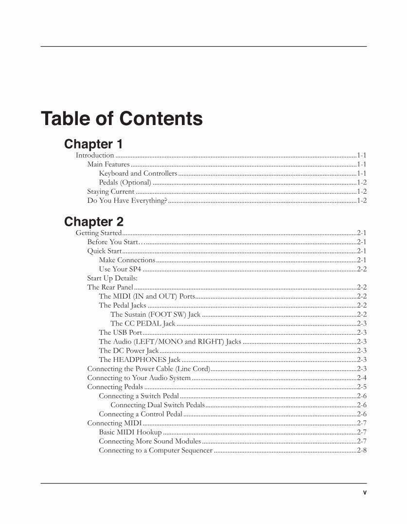
Table of ContentsChapter 1
Introduction ..............................................................................................................................................1-1Main Features .....................................................................................................................................1-1
Keyboard and Controllers .........................................................................................................1-1Pedals (Optional) ........................................................................................................................1-2
Staying Current ..................................................................................................................................1-2Do You Have Everything? ...............................................................................................................1-2
Chapter 2Getting Started ..........................................................................................................................................2-1
Before You Start… ............................................................................................................................2-1Quick Start ..........................................................................................................................................2-1
Make Connections ......................................................................................................................2-1Use Your SP4 ..............................................................................................................................2-2
Start Up Details: The Rear Panel ...................................................................................................................................2-2
The MIDI (IN and OUT) Ports ...............................................................................................2-2The Pedal Jacks ...........................................................................................................................2-2
The Sustain (FOOT SW) Jack ...........................................................................................2-2The CC PEDAL Jack ..........................................................................................................2-3
The USB Port ..............................................................................................................................2-3The Audio (LEFT/MONO and RIGHT) Jacks ...................................................................2-3The DC Power Jack ....................................................................................................................2-3The HEADPHONES Jack .......................................................................................................2-3
Connecting the Power Cable (Line Cord) ......................................................................................2-3Connecting to Your Audio System .................................................................................................2-4Connecting Pedals .............................................................................................................................2-5
Connecting a Switch Pedal ........................................................................................................2-6Connecting Dual Switch Pedals .........................................................................................2-6
Connecting a Control Pedal ......................................................................................................2-6Connecting MIDI ..............................................................................................................................2-7
Basic MIDI Hookup ..................................................................................................................2-7Connecting More Sound Modules ...........................................................................................2-7Connecting to a Computer Sequencer ....................................................................................2-8
vi
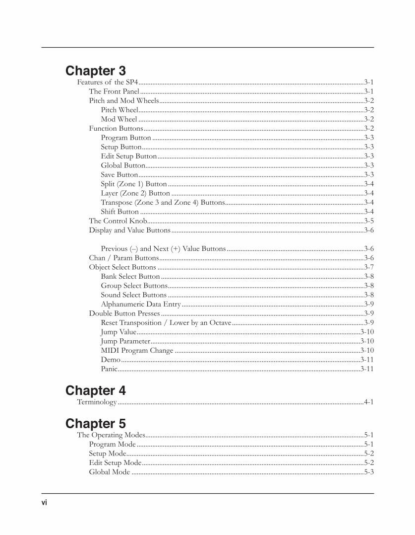
Chapter 3Features of the SP4 ..................................................................................................................................3-1
The Front Panel .................................................................................................................................3-1Pitch and Mod Wheels ......................................................................................................................3-2
Pitch Wheel ..................................................................................................................................3-2Mod Wheel ..................................................................................................................................3-2
Function Buttons ...............................................................................................................................3-2Program Button ..........................................................................................................................3-3Setup Button ................................................................................................................................3-3Edit Setup Button .......................................................................................................................3-3Global Button ..............................................................................................................................3-3Save Button ..................................................................................................................................3-3Split (Zone 1) Button .................................................................................................................3-4Layer (Zone 2) Button ...............................................................................................................3-4Transpose (Zone 3 and Zone 4) Buttons ................................................................................3-4Shift Button .................................................................................................................................3-4
The Control Knob.............................................................................................................................3-5Display and Value Buttons ...............................................................................................................3-6
Previous (–) and Next (+) Value Buttons ...............................................................................3-6
Chan / Param Buttons ......................................................................................................................3-6Object Select Buttons .......................................................................................................................3-7
Bank Select Button .....................................................................................................................3-8Group Select Buttons .................................................................................................................3-8Sound Select Buttons .................................................................................................................3-8Alphanumeric Data Entry .........................................................................................................3-9
Double Button Presses .....................................................................................................................3-9Reset Transposition / Lower by an Octave ............................................................................3-9Jump Value .................................................................................................................................3-10Jump Parameter .........................................................................................................................3-10MIDI Program Change ...........................................................................................................3-10Demo ..........................................................................................................................................3-11Panic ............................................................................................................................................3-11
Chapter 4Terminology ..............................................................................................................................................4-1
Chapter 5The Operating Modes ..............................................................................................................................5-1
Program Mode ...................................................................................................................................5-1Setup Mode .........................................................................................................................................5-2Edit Setup Mode ................................................................................................................................5-2Global Mode ......................................................................................................................................5-3
vii
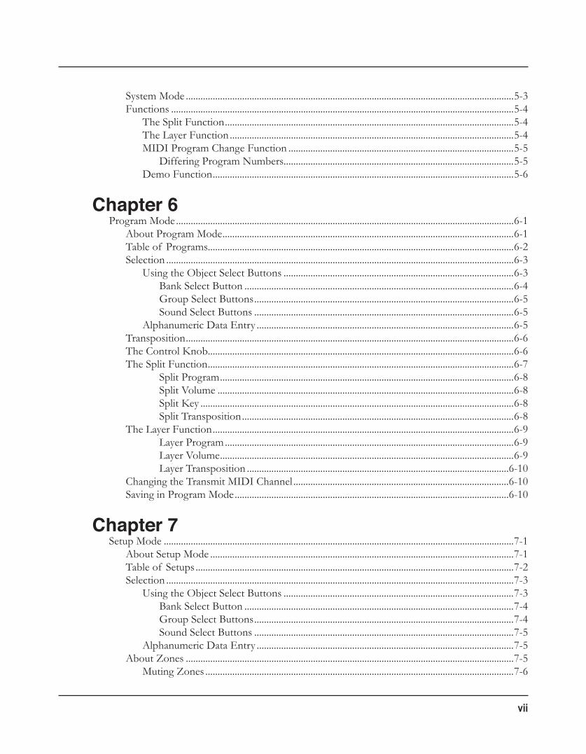
System Mode ......................................................................................................................................5-3Functions ............................................................................................................................................5-4
The Split Function ......................................................................................................................5-4The Layer Function ....................................................................................................................5-4MIDI Program Change Function ............................................................................................5-5
Differing Program Numbers..............................................................................................5-5Demo Function ...........................................................................................................................5-6
Chapter 6Program Mode ..........................................................................................................................................6-1
About Program Mode .......................................................................................................................6-1Table of Programs.............................................................................................................................6-2Selection ..............................................................................................................................................6-3
Using the Object Select Buttons ..............................................................................................6-3Bank Select Button ..............................................................................................................6-4Group Select Buttons ..........................................................................................................6-5Sound Select Buttons ..........................................................................................................6-5
Alphanumeric Data Entry .........................................................................................................6-5Transposition ......................................................................................................................................6-6The Control Knob.............................................................................................................................6-6The Split Function .............................................................................................................................6-7
Split Program ........................................................................................................................6-8Split Volume .........................................................................................................................6-8Split Key ................................................................................................................................6-8Split Transposition ...............................................................................................................6-8
The Layer Function ...........................................................................................................................6-9Layer Program ......................................................................................................................6-9Layer Volume ........................................................................................................................6-9Layer Transposition ...........................................................................................................6-10
Changing the Transmit MIDI Channel ........................................................................................6-10Saving in Program Mode ................................................................................................................6-10
Chapter 7Setup Mode ...............................................................................................................................................7-1
About Setup Mode ............................................................................................................................7-1Table of Setups ..................................................................................................................................7-2Selection ..............................................................................................................................................7-3
Using the Object Select Buttons ..............................................................................................7-3Bank Select Button ..............................................................................................................7-4Group Select Buttons ..........................................................................................................7-4Sound Select Buttons ..........................................................................................................7-5
Alphanumeric Data Entry .........................................................................................................7-5About Zones ......................................................................................................................................7-5
Muting Zones ..............................................................................................................................7-6
viii
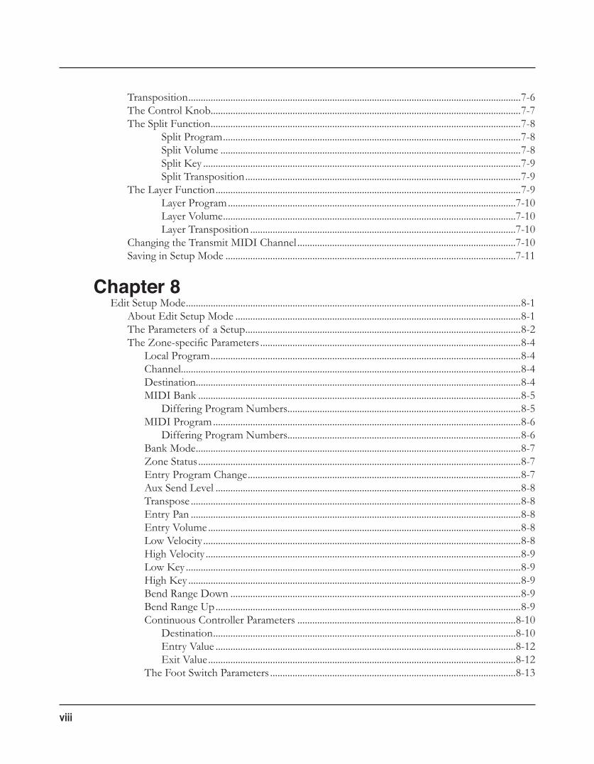
Transposition ......................................................................................................................................7-6The Control Knob.............................................................................................................................7-7The Split Function .............................................................................................................................7-8
Split Program ........................................................................................................................7-8Split Volume .........................................................................................................................7-8Split Key ................................................................................................................................7-9Split Transposition ...............................................................................................................7-9
The Layer Function ...........................................................................................................................7-9Layer Program ....................................................................................................................7-10Layer Volume ......................................................................................................................7-10Layer Transposition ...........................................................................................................7-10
Changing the Transmit MIDI Channel ........................................................................................7-10Saving in Setup Mode .....................................................................................................................7-11
Chapter 8Edit Setup Mode .......................................................................................................................................8-1
About Edit Setup Mode ...................................................................................................................8-1The Parameters of a Setup ...............................................................................................................8-2The Zone-specific Parameters .........................................................................................................8-4
Local Program .............................................................................................................................8-4Channel .........................................................................................................................................8-4Destination ...................................................................................................................................8-4MIDI Bank ..................................................................................................................................8-5
Differing Program Numbers..............................................................................................8-5MIDI Program ............................................................................................................................8-6
Differing Program Numbers..............................................................................................8-6Bank Mode ...................................................................................................................................8-7Zone Status ..................................................................................................................................8-7Entry Program Change ..............................................................................................................8-7Aux Send Level ...........................................................................................................................8-8Transpose .....................................................................................................................................8-8Entry Pan .....................................................................................................................................8-8Entry Volume ..............................................................................................................................8-8Low Velocity ................................................................................................................................8-8High Velocity ...............................................................................................................................8-9Low Key .......................................................................................................................................8-9High Key ......................................................................................................................................8-9Bend Range Down .....................................................................................................................8-9Bend Range Up ...........................................................................................................................8-9Continuous Controller Parameters ........................................................................................8-10
Destination ..........................................................................................................................8-10Entry Value .........................................................................................................................8-12Exit Value ............................................................................................................................8-12
The Foot Switch Parameters ...................................................................................................8-13
ix
Destination ..........................................................................................................................8-13Mode ....................................................................................................................................8-13Entry State ..........................................................................................................................8-13Exit State .............................................................................................................................8-13
About Auxiliary Effects ..................................................................................................................8-14Common Parameters ......................................................................................................................8-14
Aux Effect Override .................................................................................................................8-14Aux Effect Channel ..................................................................................................................8-15
Saving in Setup Mode .....................................................................................................................8-15
Chapter 9Global Mode .............................................................................................................................................9-1
Selecting and Editing Parameters ....................................................................................................9-2The Global Parameters .....................................................................................................................9-3
Tuning ...........................................................................................................................................9-3Velocity Map (VMap) .................................................................................................................9-3FX Select (FXSel) .......................................................................................................................9-4Channel Enable (ChanEn) ........................................................................................................9-4Destination (Dest) ......................................................................................................................9-4Bank Select (BankSel) .................................................................................................................9-5Program Change (ProgChg) ......................................................................................................9-5Local Keyboard Channel (LclKbdChan) ................................................................................9-6Sysex ID .......................................................................................................................................9-6
The “Hard Reset?” Dialogue ...........................................................................................................9-7The “Save All?” Dialogue .................................................................................................................9-7The “Load All?” Dialogue................................................................................................................9-8
Chapter 10System Mode ...........................................................................................................................................10-1
Buttons in System Mode ................................................................................................................10-2Run SP4 .............................................................................................................................................10-2Update Software ..............................................................................................................................10-2
Update ........................................................................................................................................10-2Restore ........................................................................................................................................10-3
Run Diagnostics ...............................................................................................................................10-3System Reset .....................................................................................................................................10-3File Utilities .......................................................................................................................................10-4
Chapter 11Tutorials ...................................................................................................................................................11-1
Creating a Setups from a Program ................................................................................................11-1Creating a Split Setup from a Program .................................................................................11-1Creating a Layer Setup from a Program ................................................................................11-4
x
Creating a Layer Setup with Velocity-dependent Zones ...........................................................11-6Controlling Multiple Modules with a Single Setup .....................................................................11-7Other Tutorials ...............................................................................................................................11-11
Connecting to Your Sound System ......................................................................................11-11Connecting MIDI ...................................................................................................................11-11Managing Object Data ...........................................................................................................11-11Updating Software ..................................................................................................................11-11Restoring Factory Defaults ....................................................................................................11-12
Chapter 12Troubleshooting ......................................................................................................................................12-1
Maintenance .....................................................................................................................................12-1Common Problems .........................................................................................................................12-1
Power Problems ........................................................................................................................12-1Audio Problems ........................................................................................................................12-3MIDI Problems .........................................................................................................................12-4
Pedal Problems.................................................................................................................................12-5Switch Pedal Problems .............................................................................................................12-5Control Pedal Problems ...........................................................................................................12-6
Use the Right Impedance, Taper, and Range ...............................................................12-6If None of the Above... .................................................................................................................12-6
Service Centers ..........................................................................................................................12-7Restoring Factory Defaults ......................................................................................................12-7Diagnostics ................................................................................................................................12-7
Appendix AMIDI Implementation ............................................................................................................................A-1
Appendix BPhysical Specifications ............................................................................................................................A-3
IntroductionMainFeatures
1-1
Chapter 1Introduction
Congratulations on your purchase of a Kurzweil SP4!
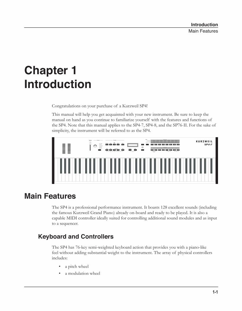
This manual will help you get acquainted with your new instrument. Be sure to keep the manual on hand as you continue to familiarize yourself with the features and functions of the SP4. Note that this manual applies to the SP4-7, SP4-8, and the SP76-II. For the sake of simplicity, the instrument will be referred to as the SP4.
Main FeaturesThe SP4 is a professional performance instrument. It boasts 128 excellent sounds (including the famous Kurzweil Grand Piano) already on-board and ready to be played. It is also a capable MIDI controller ideally suited for controlling additional sound modules and as input to a sequencer.
Keyboard and ControllersThe SP4 has 76-key semi-weighted keyboard action that provides you with a piano-like feel without adding substantial weight to the instrument. The array of physical controllers includes:
• a pitch wheel
• a modulation wheel
IntroductionStayingCurrent
1-2
• an assignable control knob, which can control a parameter of your choosing
• on the rear panel, two jacks for optional pedal controllers: one for a switch pedal and the other for a continuous controller pedal.
Pedals (Optional)As described above, the SP4 has two jacks on the rear panel for optional pedal controllers. One of these jacks is for one or two switch pedals, which are typically used to control two-state (i.e., on / off) parameters such as sustain and mute zone. The other jack is for a continuous control (or CC) pedal typically used to control multi-state (i.e., “continuous”) parameter such as filter frequency or LFO amount.
Note that switch pedals can be used to control continuous parameters just as continuous control pedals can be used to control two-state parameters.
Your Kurzweil dealer stocks the following pedals:
• FS-1 Standard box-shaped switch pedal
• KFP-1 Single piano-style switch pedal
• KFP-2S Double piano-style switch pedal unit (one stereo plug)
• CC-1 Continuous pedal
Staying CurrentBe sure to check the Kurzweil Music Systems website at www.Kurzweil.com for new documentation and software updates before using your new instrument.
Do You Have Everything?Your SP4 package should contain the following in addition to your instrument:
• Power cable and 15V power adapter
• Sustain pedal
• USB cable (Type-A-to-Type-B)
• Musician’s Guide (this book)
• Warranty card
If you don’t have all of these components, be sure to contact your Kurzweil / Young Chang dealer.
Getting StartedBeforeYouStart…
2-1
Chapter 2Getting Started
This chapter will help you hook up your SP4 to your sound system and MIDI system. If hooking up new gear is familiar to you, then simply read the following two sections in this chapter. If you need more information, then be sure to read this chapter in its entirety.
Before You Start…Don’t connect anything until you make sure your SP4 is properly and safely situated. If your SP4 has been out in the cold, give it time to warm up to room temperature before starting it, since condensation may have formed inside the SP4.
Quick Start
Make Connections1. Set the keyboard on a hard, flat, level surface.
2. Four adhesive-backed rubber feet are provided with your SP4. If you want to attach them to the bottom of the SP4 (recommended to prevent scratching your tabletop), carefully turn the keyboard over, remove the paper backing from the rubber feet and attach them near each corner all on the same level.
3. Connect the power cable to the adapter then plug the adapter’s DC power cord into your SP4. Finally, plug the power cable into the wall.
4. Make sure your sound system is at a safe volume level. Also make sure that the SP4’s MASTER VOLUME slider (on the far left side of the front panel) is all the way down.
5. Plug in a pair of stereo headphones or run standard (1/4-inch) audio cables from your amplifier or mixer to the Audio Outputs on the SP4 (use the Left out for mono). Balanced (“TRS” or “Stereo”) cables are recommended.
Getting StartedStartUpDetails:TheRearPanel
2-2
Use Your SP41. Power up your SP4 first, and then raise the MASTER VOLUME slider. The SP4 starts
up in Program mode by default. Press one of the Function buttons to the left of the display to switch Modes.
2. If you hear distortion, reduce the gain on your mixing board, or use the pad (a switch that decreases the input audio signal level, typically by 20dB) if it has one.
3. Scroll through the program list with the Previous and Next buttons under the display, or with the dedicated Bank, Group Select, and Sound Select buttons, and try the SP4’s many sounds. Take note that the User Bank is initially empty.
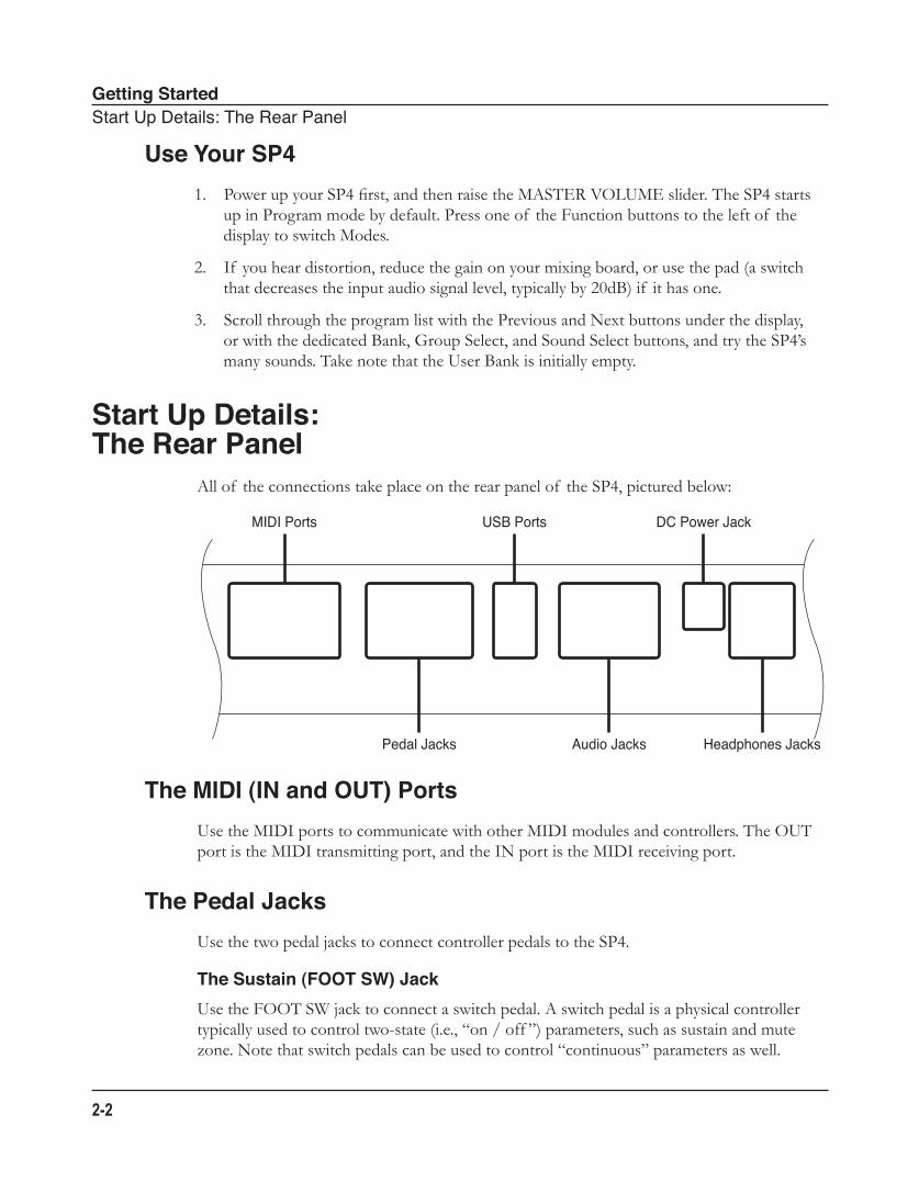
Start Up Details: The Rear Panel
All of the connections take place on the rear panel of the SP4, pictured below:
The MIDI (IN and OUT) PortsUse the MIDI ports to communicate with other MIDI modules and controllers. The OUT port is the MIDI transmitting port, and the IN port is the MIDI receiving port.
The Pedal JacksUse the two pedal jacks to connect controller pedals to the SP4.
The Sustain (FOOT SW) JackUse the FOOT SW jack to connect a switch pedal. A switch pedal is a physical controller typically used to control two-state (i.e., “on / off ”) parameters, such as sustain and mute zone. Note that switch pedals can be used to control “continuous” parameters as well.
MIDI Ports
Pedal Jacks
USB Ports DC Power Jack
Audio Jacks Headphones Jacks
Getting StartedConnectingthePowerCable(LineCord)
2-3
The jack will also accept a dual switch pedal having a single stereo plug that is available separately (Kurzweil KFP-2S). For more information on connecting pedals, see Connecting Pedals on page 2-5.
The CC PEDAL JackUse the CC PEDAL jack to connect a continuous control (or CC) pedal. A CC pedal is a physical controller typically used to control multi-state (i.e., “continuous”) parameters such as filter frequency or LFO amount. Note that CC pedals can be used to control “on / off ” parameters as well.
For more information on connecting pedals, see Connecting Pedals on page 2-5 below.
The USB PortUse the USB port to connect the SP4 to a computer in order to do the following:
• Use the SP4 as a MIDI controller with a sequencer computer program.
• Use the computer to manage the user data contents of the SP4.
• Update the software and sounds of the SP4.
Be sure to check the Kurzweil Music Systems website at www.Kurzweil.com for new documentation and software updates before using your new instrument.
The Audio (LEFT/MONO and RIGHT) JacksUse the LEFT/MONO and RIGHT audio jacks to connect the SP4 to your audio system.
The DC Power JackUse the DC power jack to connect the DC power supply.
The HEADPHONES JackUse the HEADPHONES jack to listen to the SP4 on stereo headphones. You will need a 1/4-inch-to-1/8-inch adapter in order to use headphones with a mini plug.
Connecting the Power Cable (Line Cord)The SP4 runs on 15 volts DC power. Your dealer will provide the voltage converter and power cord to match the AC power in your area: 100, 120, 230, or 240 volts at 50–60 Hz. Plug the converter into a wall outlet, and then connect the adapter to the DC power jack.
Getting StartedConnectingtoYourAudioSystem
2-4
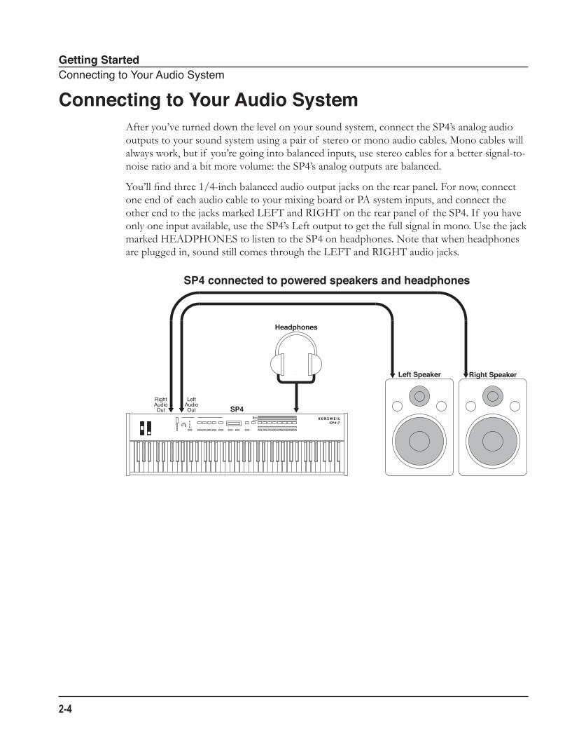
Connecting to Your Audio SystemAfter you’ve turned down the level on your sound system, connect the SP4’s analog audio outputs to your sound system using a pair of stereo or mono audio cables. Mono cables will always work, but if you’re going into balanced inputs, use stereo cables for a better signal-to-noise ratio and a bit more volume: the SP4’s analog outputs are balanced.
You’ll find three 1/4-inch balanced audio output jacks on the rear panel. For now, connect one end of each audio cable to your mixing board or PA system inputs, and connect the other end to the jacks marked LEFT and RIGHT on the rear panel of the SP4. If you have only one input available, use the SP4’s Left output to get the full signal in mono. Use the jack marked HEADPHONES to listen to the SP4 on headphones. Note that when headphones are plugged in, sound still comes through the LEFT and RIGHT audio jacks.
SP4
Left Speaker Right Speaker
RightAudioOut
LeftAudioOut
Headphones
SP4 connected to powered speakers and headphones
Getting StartedConnectingPedals
2-5
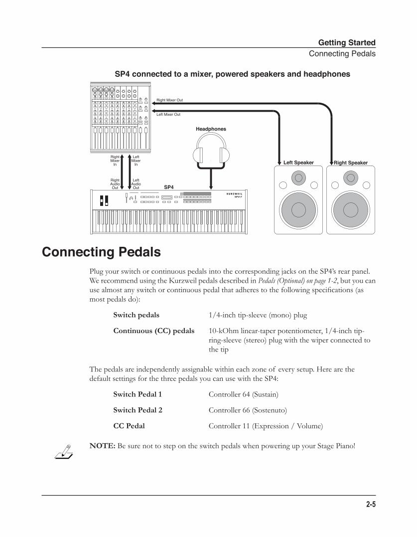
Connecting PedalsPlug your switch or continuous pedals into the corresponding jacks on the SP4’s rear panel. We recommend using the Kurzweil pedals described in Pedals (Optional) on page 1-2, but you can use almost any switch or continuous pedal that adheres to the following specifications (as most pedals do):
Switch pedals 1/4-inch tip-sleeve (mono) plug
Continuous (CC) pedals 10-kOhm linear-taper potentiometer, 1/4-inch tip-ring-sleeve (stereo) plug with the wiper connected to the tip
The pedals are independently assignable within each zone of every setup. Here are the default settings for the three pedals you can use with the SP4:
Switch Pedal 1 Controller 64 (Sustain)
Switch Pedal 2 Controller 66 (Sostenuto)
CC Pedal Controller 11 (Expression / Volume)
NOTE: Be sure not to step on the switch pedals when powering up your Stage Piano!
SP4 connected to a mixer, powered speakers and headphones
SP4
Left Speaker Right Speaker
RightAudioOut
LeftAudioOut
RightMixer
In
LeftMixer
In
Right Mixer Out
Left Mixer Out
Headphones
Getting StartedConnectingMIDI
2-6
Connecting a Switch PedalWhen plugged into the FOOTSW jack on the rear-panel, a single switch pedal will, by default, act like a sustain pedal. Of course this can be changed by programming, as described in Setup Mode on page 7-1.
If you use a third-party (non-Kurzweil) switch pedal, make sure it’s connected before you turn on your SP4. This ensures that the pedal will work properly (it might function in reverse—off when it’s down and on when it’s up—if you turn on your SP4 before plugging in the pedal). Similarly, don’t press any of your switch pedals while powering up, as the SP4 verifies each pedal’s orientation during power up—if you’re pressing a pedal, you might cause it to work in reverse.
See Switch Pedal Problems on page 12-5 if you are having trouble with your switch pedal.
Connecting Dual Switch PedalsThe jack will also accept a dual switch pedal having a single stereo plug. The plug should be wired so that the left pedal connects to the ring contact and the right pedal to the tip contact. It’s also possible to use two single pedals with this jack: first buy a 1/4-inch stereo-to-dual-mono Y adapter (this will have two mono 1/4-inch phone jacks and a stereo 1/4-inch plug); then, plug the pedal you wish to use for sustain into the left jack and your sostenuto pedal into the right jack. Note that the “left” pedal goes into the right jack and vice-versa.
By default, the right pedal will control sustain as before and the left pedal will control the sostenuto function. If you’re not familiar with traditional piano technique, the sostenuto (center) pedal on a grand piano allows one to hold chords in the bass while continuing to play the melody without the latter notes sustaining. Any keys that are down when you depress the pedal will sustain when you let go of the keys, but new notes played afterward will not be sustained. Releasing the pedal puts things back to normal. Of course it can be programmed to do other functions as well.
Connecting a Control PedalA control pedal can be very useful for controlling volume, vibrato, or other effect by foot. The Kurzweil CC-1 control pedal will work best with the SP4, but it is also possible to use third-party control pedals designed for synthesizers. Note that a volume pedal may or may not be satisfactory depending on how it is constructed.
See Control Pedal Problems on page 12-6 if you are having trouble with your control pedal.
Getting StartedConnectingMIDI
2-7
Connecting MIDIIn addition to being a performance-suited musical instrument, the SP4 is a powerful, but intuitive and easy-to-use MIDI controller. For descriptions of how to customize your SP4 as MIDI controller, and how to use its MIDI controller capabilities to their fullest potential, see Setup Mode on page 7-1.
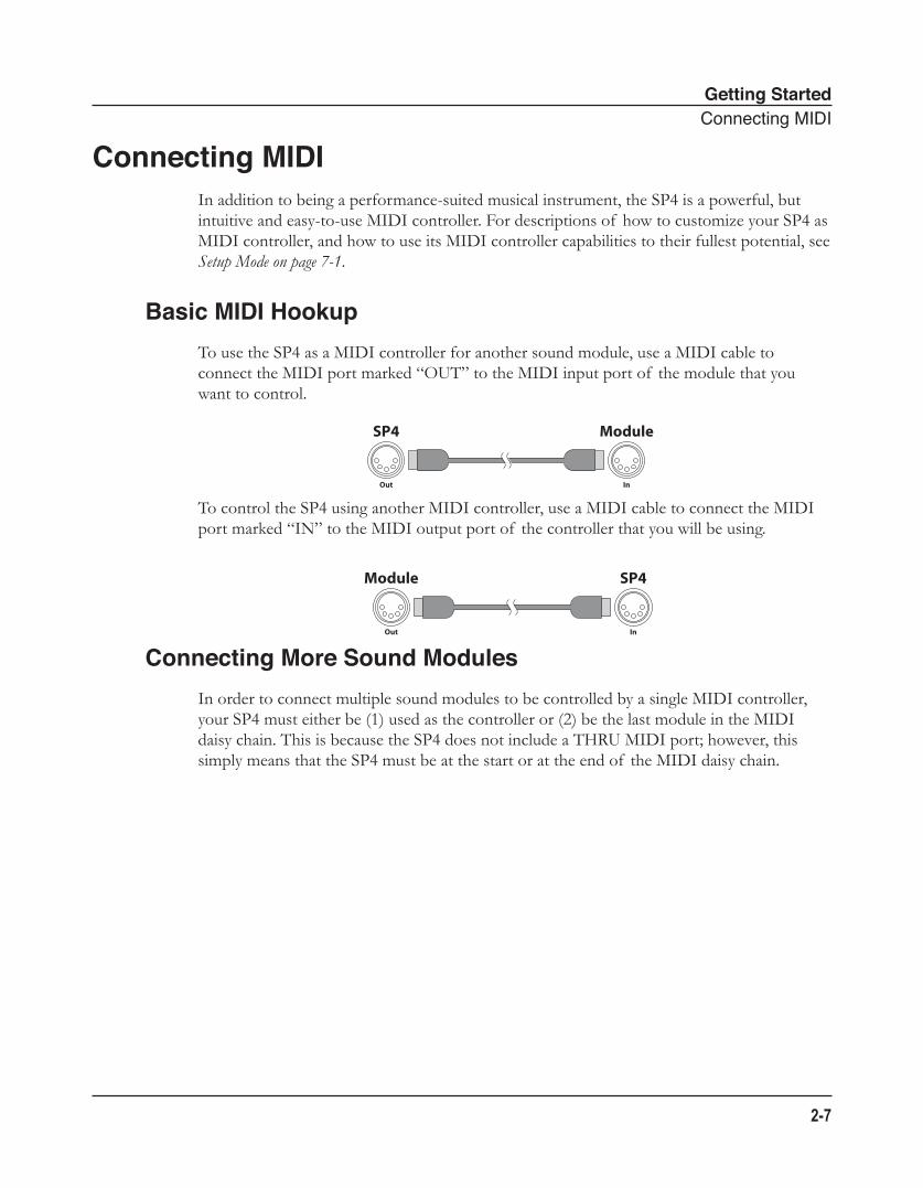
Basic MIDI HookupTo use the SP4 as a MIDI controller for another sound module, use a MIDI cable to connect the MIDI port marked “OUT” to the MIDI input port of the module that you want to control.
To control the SP4 using another MIDI controller, use a MIDI cable to connect the MIDI port marked “IN” to the MIDI output port of the controller that you will be using.
Connecting More Sound ModulesIn order to connect multiple sound modules to be controlled by a single MIDI controller, your SP4 must either be (1) used as the controller or (2) be the last module in the MIDI daisy chain. This is because the SP4 does not include a THRU MIDI port; however, this simply means that the SP4 must be at the start or at the end of the MIDI daisy chain.
SP4 Module
Out In
Module SP4
Out In
Getting StartedConnectingMIDI
2-8
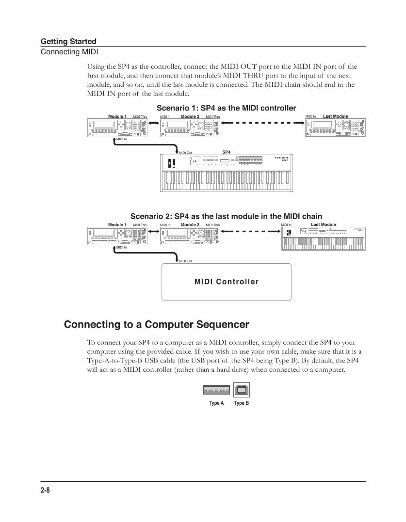
Using the SP4 as the controller, connect the MIDI OUT port to the MIDI IN port of the first module, and then connect that module’s MIDI THRU port to the input of the next module, and so on, until the last module is connected. The MIDI chain should end in the MIDI IN port of the last module.
Connecting to a Computer SequencerTo connect your SP4 to a computer as a MIDI controller, simply connect the SP4 to your computer using the provided cable. If you wish to use your own cable, make sure that it is a Type-A-to-Type-B USB cable (the USB port of the SP4 being Type B). By default, the SP4 will act as a MIDI controller (rather than a hard drive) when connected to a computer.
Scenario 1: SP4 as the MIDI controller
SP4
MIDI In
Module 1 MIDI Thru Module 2MIDI In MIDI Thru Last ModuleMIDI In
MIDI Out
Scenario 2: SP4 as the last module in the MIDI chain
MIDI In
Module 1 MIDI Thru Module 2MIDI In MIDI Thru Last ModuleMIDI In
MIDI Out
MIDI Controller
Features of the SP4TheFrontPanel
3-1
Chapter 3Features of the SP4
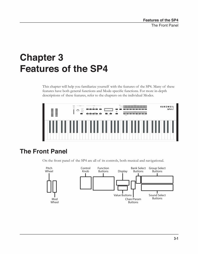
This chapter will help you familiarize yourself with the features of the SP4. Many of these features have both general functions and Mode-specific functions. For more in-depth descriptions of these features, refer to the chapters on the individual Modes.
The Front PanelOn the front panel of the SP4 are all of its controls, both musical and navigational.
PitchWheel
ModWheel
ControlKnob
FunctionButtons Display
Bank SelectButtons
Group SelectButtons
Sound SelectButtonsChan/Param
Buttons
Value Buttons
Features of the SP4PitchandModWheels
3-2
Pitch and Mod Wheels
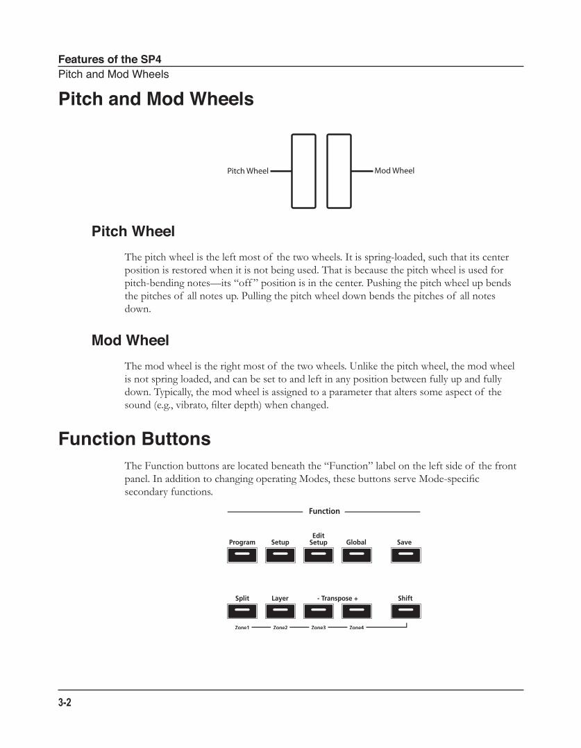
Pitch WheelThe pitch wheel is the left most of the two wheels. It is spring-loaded, such that its center position is restored when it is not being used. That is because the pitch wheel is used for pitch-bending notes—its “off ” position is in the center. Pushing the pitch wheel up bends the pitches of all notes up. Pulling the pitch wheel down bends the pitches of all notes down.
Mod WheelThe mod wheel is the right most of the two wheels. Unlike the pitch wheel, the mod wheel is not spring loaded, and can be set to and left in any position between fully up and fully down. Typically, the mod wheel is assigned to a parameter that alters some aspect of the sound (e.g., vibrato, filter depth) when changed.
Function ButtonsThe Function buttons are located beneath the “Function” label on the left side of the front panel. In addition to changing operating Modes, these buttons serve Mode-specific secondary functions.
Pitch Wheel Mod Wheel
Features of the SP4FunctionButtons
3-3
Program ButtonPressing the Program button will take you into Program Mode (described in The Operating Modes on page 5-1 and, in further detail, in Program Mode on page 6-1). In Program Mode, you can select and play different sounds (or “Programs”).
This button’s LED will be illuminated when you are in Program Mode.
Setup ButtonPressing the Setup button will take you into Setup Mode (described in The Operating Modes on page 5-1 and, in further detail, in Setup Mode on page 7-1). In Setup Mode, you can select different configurations (or “Setups”) of Programs, controller assignments, and MIDI channel assignments.
This button’s LED will be illuminated when you are in Setup Mode.
Edit Setup ButtonPressing the Edit Setup button will take you into Edit Setup Mode (described in The Operating Modes on page 5-1 and, in further detail, in Edit Setup Mode on page 8-1). In Edit Setup Mode, you can edit or create Setups.
This button’s LED will be illuminated when you are in Edit Setup Mode.
Global ButtonPressing the Global button will take you into Global Mode (described in The Operating Modes on page 5-1 and, in further detail, in Global Mode on page 9-1). In Global Mode, you can edit parameters that control the entire SP4. These include tuning, transposition, and velocity and aftertouch sensitivity. Additionally, you can perform a hard reset in this Mode.
CAUTION: PERFORMING A HARD RESET WILL DELETE ALL USER-CREATED PROGRAMS, SETUPS, AND GLOBAL SETTINGS.
This button’s LED will be illuminated when you are in Global Mode.
Save ButtonPressing the Save button will allow you to save any custom Programs or Setups that you’ve created, or save any changes made to the current Program or Setup. This button’s LED will appear illuminated once you have made changes to the current Program or Setup.
Features of the SP4TheControlKnob
3-4
Split (Zone 1) ButtonPressing the Split button will perform the Split Function. With the Split Function, you can split the keyboard into up to four Zones, and assign different programs, MIDI settings, and transpositions to each Zone. The Split Function is described further in The Split Function on page 5-4.
When in Setup Mode, holding down the Shift button while pressing the Split button will mute or unmute (depending on the state of the zone) Zone 1 of the current setup.
Layer (Zone 2) ButtonPressing the Layer button will perform the Layer Function. With the Layer Function, you can layer up to four different programs and setups – each layer is a new Zone, of which you can have a maximum of four. The Layer Function is described further in The Layer Function on page 5-4.
When in Setup Mode, holding down the Shift button while pressing the Layer button will mute or unmute (depending on the state of the zone) Zone 2 of the current setup.
Transpose (Zone 3 and Zone 4) ButtonsPressing the Transpose + button will transpose the current program or setup up by one semitone; pressing the Transpose – button will transpose the current program or setup down by one semitone. Pressing both Transpose + and Transpose – simultaneously will restore the current program or setup to having no transposition; if these two buttons are simultaneously pressed when there is already no transposition, then the current program or setup will be transposed down by one octave (12 semitones).
When in Setup Mode, holding down the Shift button while pressing the Transpose – button will mute or unmute (depending on the state of the zone) Zone 3 of the current setup. Holding down the Shift button while pressing the Transpose + button will mute or unmute (depending on the state of the zone) Zone 4 of the current setup.
Shift ButtonWhen in Setup Mode, holding down the Shift button activates the secondary functions (i.e., Zone mute) of the Split, Layer, Transpose –, and Transpose + buttons. When holding down the Shift button, the button of each active zone will be illuminated and the button of each muted zone will be blinking.
Features of the SP4TheControlKnob
3-5
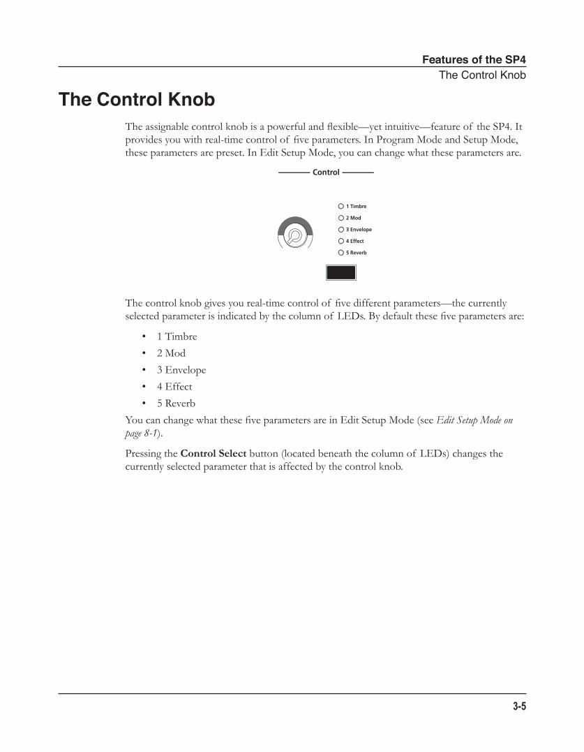
The Control KnobThe assignable control knob is a powerful and flexible—yet intuitive—feature of the SP4. It provides you with real-time control of five parameters. In Program Mode and Setup Mode, these parameters are preset. In Edit Setup Mode, you can change what these parameters are.
The control knob gives you real-time control of five different parameters—the currently selected parameter is indicated by the column of LEDs. By default these five parameters are:
• 1 Timbre
• 2 Mod
• 3 Envelope
• 4 Effect
• 5 Reverb
You can change what these five parameters are in Edit Setup Mode (see Edit Setup Mode on page 8-1).
Pressing the Control Select button (located beneath the column of LEDs) changes the currently selected parameter that is affected by the control knob.
Features of the SP4DisplayandValueButtons
3-6
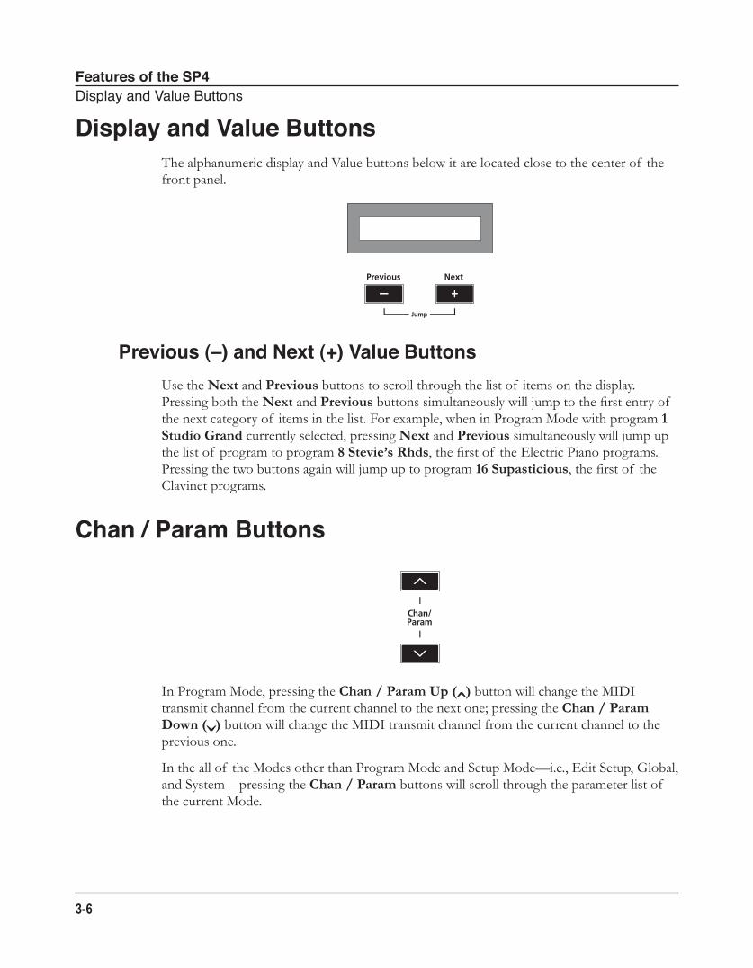
Display and Value ButtonsThe alphanumeric display and Value buttons below it are located close to the center of the front panel.
Previous (–) and Next (+) Value Buttons
Use the Next and Previous buttons to scroll through the list of items on the display. Pressing both the Next and Previous buttons simultaneously will jump to the first entry of the next category of items in the list. For example, when in Program Mode with program 1 Studio Grand currently selected, pressing Next and Previous simultaneously will jump up the list of program to program 8 Stevie’s Rhds, the first of the Electric Piano programs. Pressing the two buttons again will jump up to program 16 Supasticious, the first of the Clavinet programs.
Chan / Param Buttons
In Program Mode, pressing the Chan / Param Up (̂) button will change the MIDI transmit channel from the current channel to the next one; pressing the Chan / Param Down (̌) button will change the MIDI transmit channel from the current channel to the previous one.
In the all of the Modes other than Program Mode and Setup Mode—i.e., Edit Setup, Global, and System—pressing the Chan / Param buttons will scroll through the parameter list of the current Mode.
Features of the SP4ObjectSelectButtons
3-7
Object Select Buttons
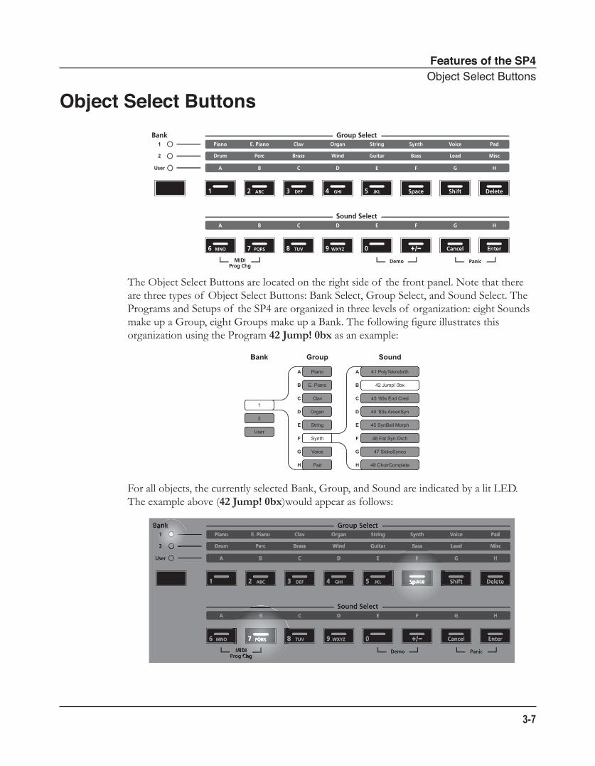
The Object Select Buttons are located on the right side of the front panel. Note that there are three types of Object Select Buttons: Bank Select, Group Select, and Sound Select. The Programs and Setups of the SP4 are organized in three levels of organization: eight Sounds make up a Group, eight Groups make up a Bank. The following figure illustrates this organization using the Program 42 Jump! 0bx as an example:
For all objects, the currently selected Bank, Group, and Sound are indicated by a lit LED. The example above (42 Jump! 0bx)would appear as follows:
Bank Group Sound
A
B
C
D
E
F
G
H
A
B
C
D
E
F
G
H
1
2
User
Piano
E. Piano
Clav
Organ
String
Synth
Voice
Pad
41 PolyTeknobrth
42 Jump! 0bx
43 ‘80s End Cred
44 ‘80s AreanSyn
45 SynBell Morph
46 Fat Syn Orch
47 SickoSynco
48 ChoirComplete
Features of the SP4ObjectSelectButtons
3-8
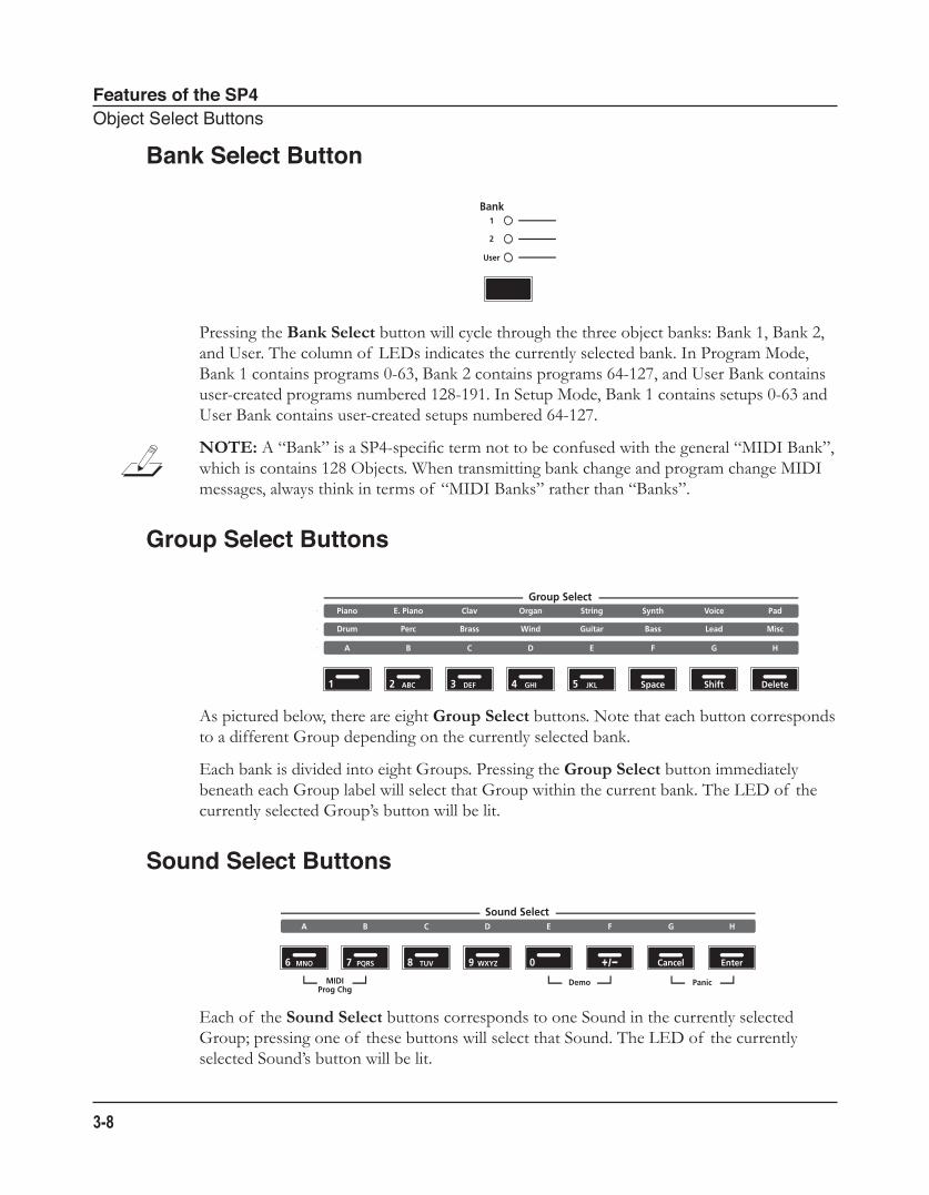
Bank Select Button
Pressing the Bank Select button will cycle through the three object banks: Bank 1, Bank 2, and User. The column of LEDs indicates the currently selected bank. In Program Mode, Bank 1 contains programs 0-63, Bank 2 contains programs 64-127, and User Bank contains user-created programs numbered 128-191. In Setup Mode, Bank 1 contains setups 0-63 and User Bank contains user-created setups numbered 64-127.
NOTE: A “Bank” is a SP4-specific term not to be confused with the general “MIDI Bank”, which is contains 128 Objects. When transmitting bank change and program change MIDI messages, always think in terms of “MIDI Banks” rather than “Banks”.
Group Select Buttons
As pictured below, there are eight Group Select buttons. Note that each button corresponds to a different Group depending on the currently selected bank.
Each bank is divided into eight Groups. Pressing the Group Select button immediately beneath each Group label will select that Group within the current bank. The LED of the currently selected Group’s button will be lit.
Sound Select Buttons
Each of the Sound Select buttons corresponds to one Sound in the currently selected Group; pressing one of these buttons will select that Sound. The LED of the currently selected Sound’s button will be lit.
Features of the SP4DoubleButtonPresses
3-9
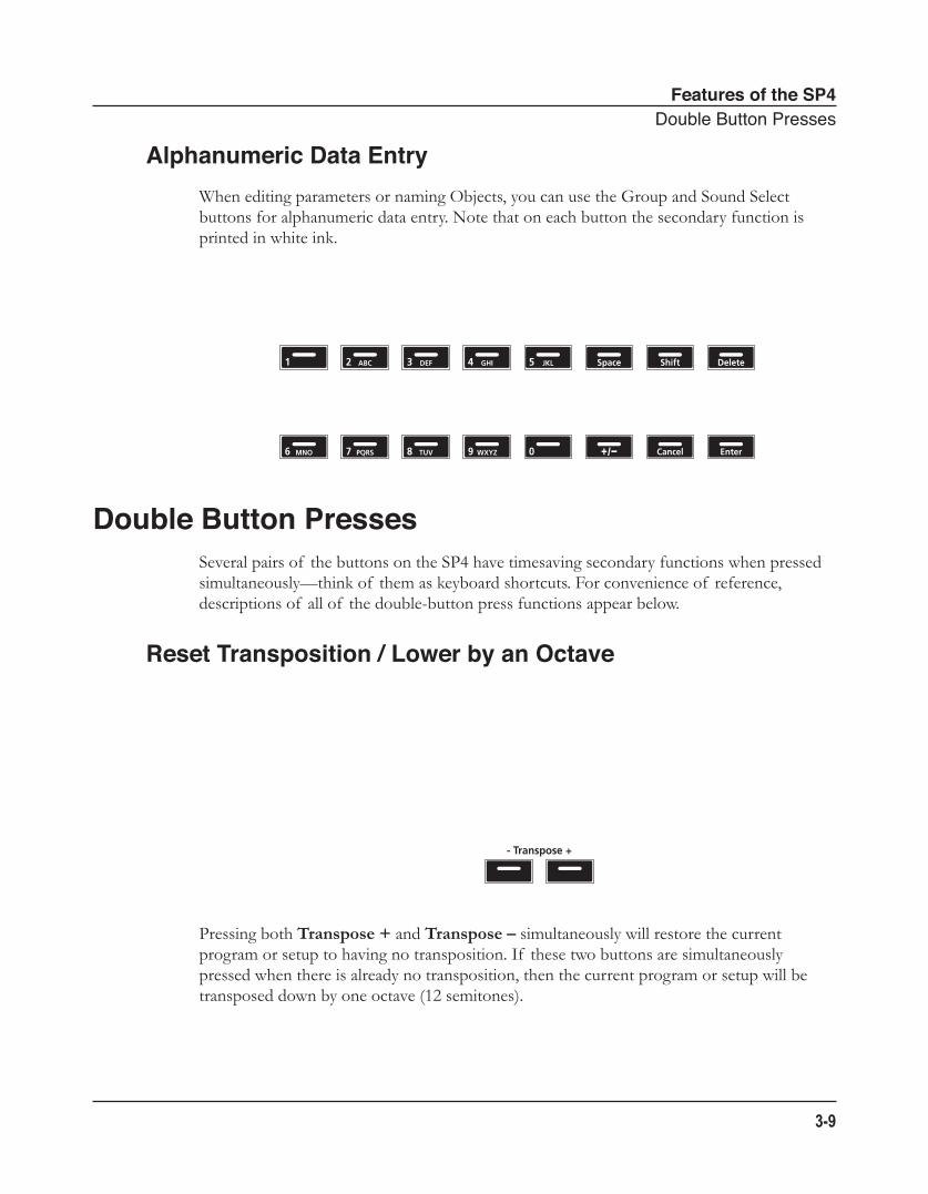
Alphanumeric Data EntryWhen editing parameters or naming Objects, you can use the Group and Sound Select buttons for alphanumeric data entry. Note that on each button the secondary function is printed in white ink.
Double Button PressesSeveral pairs of the buttons on the SP4 have timesaving secondary functions when pressed simultaneously—think of them as keyboard shortcuts. For convenience of reference, descriptions of all of the double-button press functions appear below.
Reset Transposition / Lower by an Octave
Pressing both Transpose + and Transpose – simultaneously will restore the current program or setup to having no transposition. If these two buttons are simultaneously pressed when there is already no transposition, then the current program or setup will be transposed down by one octave (12 semitones).
Features of the SP4DoubleButtonPresses
3-10
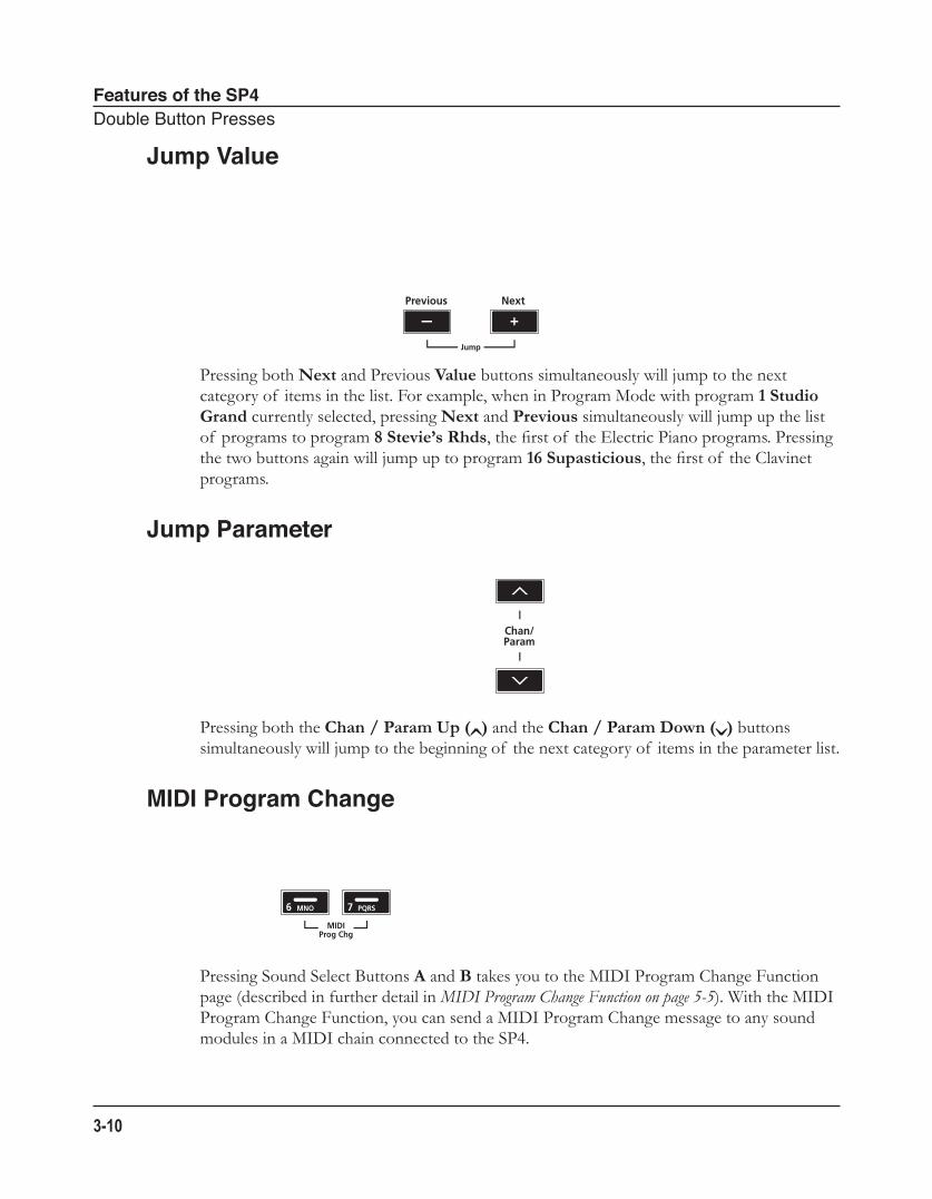
Jump Value
Pressing both Next and Previous Value buttons simultaneously will jump to the next category of items in the list. For example, when in Program Mode with program 1 Studio Grand currently selected, pressing Next and Previous simultaneously will jump up the list of programs to program 8 Stevie’s Rhds, the first of the Electric Piano programs. Pressing the two buttons again will jump up to program 16 Supasticious, the first of the Clavinet programs.
Jump Parameter
Pressing both the Chan / Param Up (̂) and the Chan / Param Down (̌) buttons simultaneously will jump to the beginning of the next category of items in the parameter list.
MIDI Program Change
Pressing Sound Select Buttons A and B takes you to the MIDI Program Change Function page (described in further detail in MIDI Program Change Function on page 5-5). With the MIDI Program Change Function, you can send a MIDI Program Change message to any sound modules in a MIDI chain connected to the SP4.
Features of the SP4DoubleButtonPresses
3-11
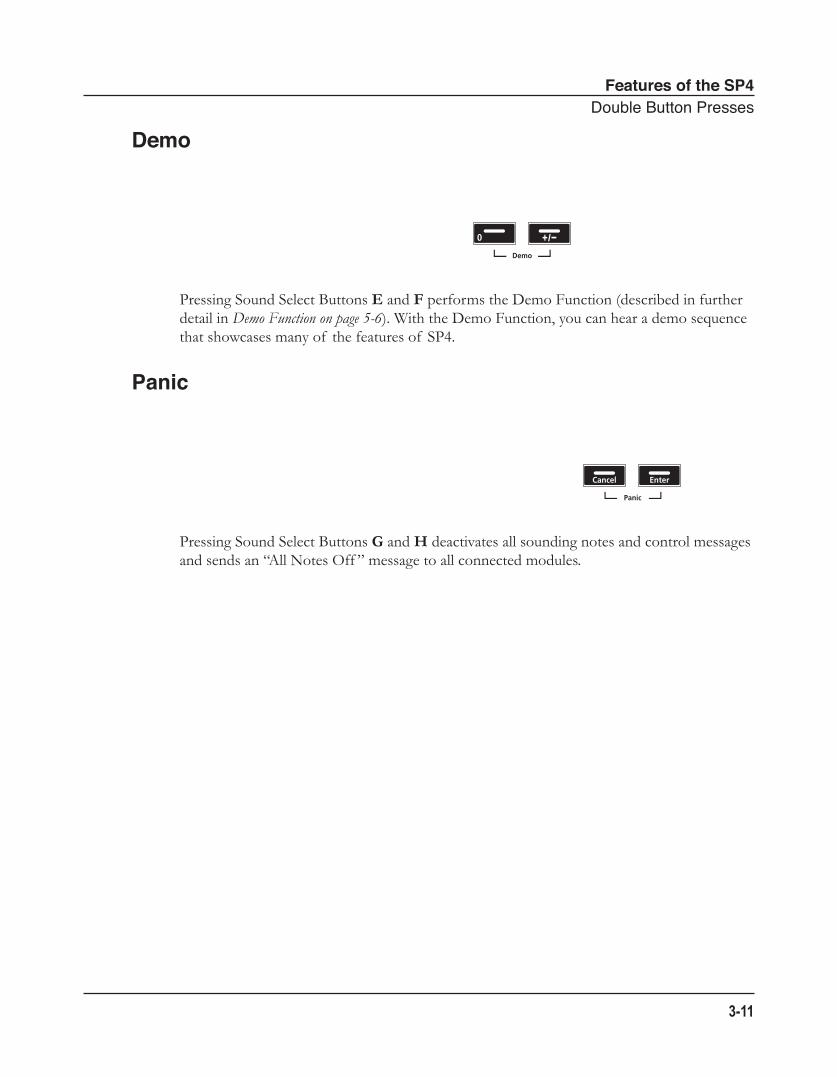
Demo
Pressing Sound Select Buttons E and F performs the Demo Function (described in further detail in Demo Function on page 5-6). With the Demo Function, you can hear a demo sequence that showcases many of the features of SP4.
Panic
Pressing Sound Select Buttons G and H deactivates all sounding notes and control messages and sends an “All Notes Off ” message to all connected modules.
Features of the SP4DoubleButtonPresses
3-12
Terminology
4-1
Chapter 4Terminology
This chapter provides definitions and descriptions for all of the SP4-specific terms use in this manual. Note that some of the terms are also used by other manufactures. Since there are no standard definitions for some of these terms, they are described here to avoid confusion. All of these terms appear capitalized as proper nouns in this manual to make it easy to distinguish between the generic term and the SP4-specific term.
Object Anything that can be named, saved, deleted, or edited (i.e., a Program or a Setup). See Program Mode on page 6-1 and Setup Mode on page 7-1 for moreinformation on Objects.
Program A factory-preset or user-programmed sounds stored in ROM or flash memory, each with five parameters that can be changed in real-time with the control knob. See Program Mode on page 6-1 for more information on Programs.
Setup A factory-preset or user-programmed MIDI performance presets consisting of up to 4 Zones, each with its own keyboard region, Program, MIDI channel, and controller assignments. See Setup Mode on page 7-1 for more information on Setups.
Zone A keyboard region of a Setup that has its own Program, MIDI channel, and controller assignments. See Setup Mode on page 7-1 for more information on Zones.
Split A division of Zones in a Setup. See The Split Function on page 5-4 for more information on Splits.
Layer An overlap of Zones in a Setup. See The Layer Function on page 5-4 for more information on Layers.
Terminology
4-2
Bank The first and highest level of Object organization; contains eight Groups and thus 64 Sounds; different from a “MIDI Bank”, which will be referred to as such. See Using the Object Select Buttons on page 6-3 or Using the Object Select Buttons on page 7-3 for more information on Banks and Object organization.
MIDI Bank The highest level of Object organization by the MIDI standard; contains 128 Objects; different from a “Bank”.
Group The second level of Object organization; contains eight Sounds. See Using the Object Select Buttons on page 6-3 or Using the Object Select Buttons on page 7-3 for more information on Groups and Object organization.
Sound The third lowest level of Object organization; can be either a Program or a Setup depending on the current Mode. See Using the Object Select Buttons on page 6-3 or Using the Object Select Buttons on page 7-3 for more information on Sounds and Object organization.
Mode An operating status with a unique group of operations. See The Operating Modes on page 5-1 for more information on Modes.
The Operating ModesProgramMode
5-1
Chapter 5The Operating Modes
This chapter will help you familiarize yourself with the operating modes of the SP4. Each of the five Modes (Program, Setup, Edit Setup, Global, and System) has its own individual chapter—the four Functions (Split, Layer, MIDI Program Change, and Demo) are described in this chapter in Functions on page 5-4.
Program ModeProgram mode is the default mode of the SP4. In this mode, you can select, play, and edit programs. To enter Program mode from another mode, press the Program Function button.
For more detailed information on Program mode, see Program Mode on page 6-1.
The Operating ModesSetupMode
5-2
Setup ModeSetup mode allows you to select and play setups. Setups are configurations of up to four zones, each of which may have its own program and controller assignments. To enter Setup mode from another mode, press the Setup Function button.
For more detailed information on Setup mode, see Setup Mode on page 7-1.
Edit Setup ModeEdit Setup mode allows you to create setups or edit preexisting setups. To enter Edit Setup mode from another mode, press the Edit Setup Function button.
For more detailed information on Edit Setup mode, see Edit Setup Mode on page 8-1.
The Operating ModesGlobalMode
5-3
Global ModeCAUTION: READ Global Mode on page 9-1 BEFORE USING GLOBAL MODE. THIS MODE CONTAINS CERTAIN OPERATIONS THAT CANNOT BE UNDONE.
Global mode allows you to edit global parameters and MIDI settings, or restore factory defaults with a hard reset. To enter Global mode from another mode, press the Global Function button.
System ModeCAUTION: READ System Mode on page 10-1 BEFORE ATTEMPTING TO ENTER SYSTEM MODE. THIS MODE CONTAINS CERTAIN OPERATIONS THAT CANNOT BE UNDONE.
System Mode allows you manage and upgrade the OS software of your SP4 as well as perform diagnostic tests of the instrument’s various internal systems and processes. Note that the functions that you have access to in System Mode govern the operation of your SP4, so only use System Mode when you must perform essential maintenance tasks.
To enter System Mode, follow these steps:
1. Power off your SP4.
2. Press and the hold the Shift button, and power on the unit. Make sure to keep holding the Shift button unit the text “SP4 bootloader vx.x” (where x.x is the version of the bootloader software) scrolls across the display.
3. Release the Shift button—at this point, you are in System Mode.
The Operating ModesFunctions
5-4
FunctionsIn addition to the five primary Modes, there are four Functions. These Functions are not as complex as the primary Modes and are described below.
The Split FunctionPressing the Split Function button while in either Program or Setup mode will perform the Split Function. The Split Function allows you to split programs and setups such that keys in one region of the keyboard produce different sounds than another region.
Creating Splits in Program Mode is slightly different from creating Splits in Setup Mode. See The Split Function on page 6-7 (for Splits in Program Mode) and The Split Function on page 7-8 (for Splits in Setup Mode).
The Layer FunctionPressing the Layer Function button while in either Program or Setup mode will perform the Layer Function. The Layer Function allows you to layer programs and setups such that more than one sound can be produced by striking one key.
The Operating ModesFunctions
5-5
Creating Layers in Program Mode is slightly different from creating Splits in Setup Mode. See The Layer Function on page 6-9 (for Layers in Program Mode) and The Layer Function on page 7-9 (for Layers in Setup Mode).
MIDI Program Change FunctionPressing both the Sound Select A and Sound Select B buttons simultaneously will take you into the MIDI Program Change Function page.
With this Function, you can send a MIDI Program Change message to connected sound modules. Doing so will not affect the local sound (that is, it will not affect the currently selected program on the SP4). Using the secondary functions of the Group Select and Sound Select buttons, you can enter program numbers from 0 to 2,097,152—this seemingly random number comes from the fact that, by the General MIDI Standard, you can send Program messages for up to 16,384 MIDI Banks, each containing up to 128 programs.
When a message is sent with the MIDI Program Change Function, any Global setting that might disable MIDI Transmit or might disable MIDI Program Change is ignored. After the MIDI Program Change message is sent, the SP4 will automatically return to the previous mode.
A MIDI Program Change message can be canceled by pressing any button other than the Numeric Entry buttons or the Value buttons.
NOTE: A “Bank” is a SP4-specific term not to be confused with the general “MIDI Bank”, which is contains 128 Objects. When transmitting MIDI Bank Change and MIDI Program Change messages, always think in terms of “MIDI Banks” rather than “Banks”.
Differing Program NumbersIf the programs on your connected sound module are organized by MIDI Bank with each program number being between 0 and 127, then use the following formula to determine what number to enter for the MIDI Program Change Function:
[MIDI Bank number] * 128 + [program number] - 1
So for example, if you want to send to a MIDI Program Change message for Program 83 in MIDI Bank 4, you would enter the number 594—this number is equal to 4 * 128 + 83 - 1.
If the programs on your connected sound module are organized by MIDI Bank with each program number being between 1 and 128, then use the following formula to determine what number to enter in MIDI Program Change mode:
The Operating ModesFunctions
5-6
[MIDI Bank number] * 128 + [program number]
So for example, if you want to send to a MIDI Program Change message for Program 83 in MIDI Bank 4, you would enter the number 595—this number is equal to 4 * 128 + 83.
Demo FunctionPressing the Sound Select E and F buttons simultaneously performs the Demo Function.
Entering this mode, the SP4 will play a built-in demo sequence designed to demonstrate the capabilities of the instrument. While the demo sequence plays, the display will show the text “Demo Mode,” and the Sound Select E and Sound Select F button LEDs will blink, indicating that the instrument is in Demo Mode. Pressing any button will return to the previous mode.
Program ModeAboutProgramMode
6-1
Chapter 6Program Mode
This chapter will help you familiarize yourself with the features of Program mode.
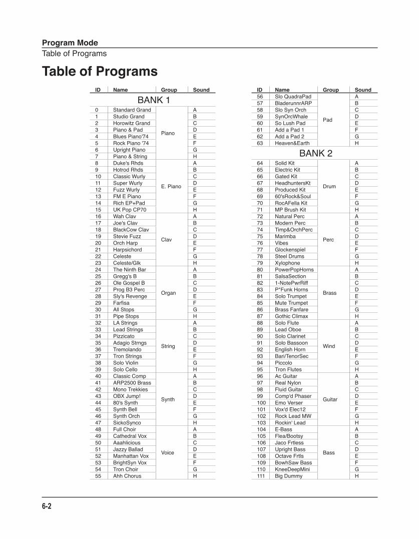
Programs are essentially the different sounds of a MIDI instrument—they are preset sound Objects equivalent to the “patches,” “presets,” or “voices” that you find on other synths. On the SP4, you can have up to 192 different Programs organized in three different Banks: Bank 1 (Programs 0-63) and Bank 2 (programs 64-127) provide you with 128 ready-to-play factory Programs, and the User Bank provides you with 64 slots for user-created Programs.
About Program ModeProgram mode is the default mode of the SP4—the SP4 starts up in this mode. To enter Program mode from another mode, press the Program Function button. While you are in Program mode, the Program button’s indicator LED is illuminated. Also by default, the SP4 starts up with Program 0 Grand Piano selected. If you enter Program mode from another mode, the last selected Program will be the current Program.
Program ModeTableofPrograms
6-2
Table of ProgramsID Name Group Sound ID Name Group Sound
BANK1 56 SloQuadraPad
Pad
A57 BladerunnrARP B
0 StandardGrand
Piano
A 58 SloSynOrch C1 StudioGrand B 59 SynOrcWhale D2 HorowitzGrand C 60 SoLushPad E3 Piano&Pad D 61 AddaPad1 F4 BluesPiano'74 E 62 AddaPad2 G5 RockPiano'74 F 63 Heaven&Earth H6 UprightPiano G BANK27 Piano&String H8 Duke'sRhds
E.Piano
A 64 SolidKit
Drum
A9 HotrodRhds B 65 ElectricKit B10 ClassicWurly C 66 GatedKit C11 SuperWurly D 67 HeadhuntersKt D12 FuzzWurly E 68 ProducedKit E13 FMEPiano F 69 60'sRock&Soul F14 RichEP+Pad G 70 RocAFellaKit G15 UKPopCP70 H 71 MPBrushKit H16 WahClav
Clav
A 72 NaturalPerc
Perc
A17 Joe'sClav B 73 ModernPerc B18 BlackCowClav C 74 Timp&OrchPerc C19 StevieFuzz D 75 Marimba D20 OrchHarp E 76 Vibes E21 Harpsichord F 77 Glockenspiel F22 Celeste G 78 SteelDrums G23 Celeste/Glk H 79 Xylophone H24 TheNinthBar
Organ
A 80 PowerPopHorns
Brass
A25 Gregg'sB B 81 SalsaSection B26 OleGospelB C 82 1-NotePwrRiff C27 ProgB3Perc D 83 P*FunkHorns D28 Sly'sRevenge E 84 SoloTrumpet E29 Farfisa F 85 MuteTrumpet F30 AllStops G 86 BrassFanfare G31 PipeStops H 87 GothicClimax H32 LAStrings
String
A 88 SoloFlute
Wind
A33 LeadStrings B 89 LeadOboe B34 Pizzicato C 90 SoloClarinet C35 AdagioStrngs D 91 SoloBassoon D36 Tremolando E 92 EnglishHorn E37 TronStrings F 93 Bari/TenorSec F38 SoloViolin G 94 Piccolo G39 SoloCello H 95 TronFlutes H40 ClassicComp
Synth
A 96 AcGuitar
Guitar
A41 ARP2500Brass B 97 RealNylon B42 MonoTrekkies C 98 FluidGuitar C43 OBXJump! D 99 Comp'dPhaser D44 80'sSynth E 100 EmoVerser E45 SynthBell F 101 Vox'dElec12 F46 SynthOrch G 102 RockLeadMW G47 SickoSynco H 103 Rockin'Lead H48 FullChoir
Voice
A 104 E-Bass
Bass
A49 CathedralVox B 105 Flea/Bootsy B50 Aaahlicious C 106 JacoFrtless C51 JazzyBallad D 107 UprightBass D52 ManhattanVox E 108 OctaveFrtls E53 BrightSynVox F 109 BowhSawBass F54 TronChoir G 110 KneeDeepMini G55 AhhChorus H 111 BigDummy H
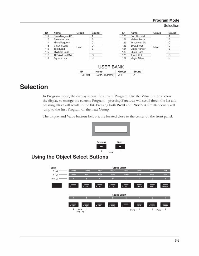
Program ModeSelection
6-3
ID Name Group Sound ID Name Group Sound112 Saw+Mogue4P
Lead
A 120 BrazilAccord
Misc
A113 EmersonLead B 121 MellowAccord B114 MicroMogue+ C 122 WindsHornStr C115 VSyncLead D 123 Strs&Silver D116 TootLead E 124 ChinaFlower E117 MWheelLead F 125 BluesHarp F118 12SAWLeadMW G 126 TouchKoto G119 SquareLead H 127 MagicMbira H
USERBANKID Name Group Sound128–191 (User Programs) A–H A–H
SelectionIn Program mode, the display shows the current Program. Use the Value buttons below the display to change the current Program—pressing Previous will scroll down the list and pressing Next will scroll up the list. Pressing both Next and Previous simultaneously will jump to the first Program of the next Group.
The display and Value buttons below it are located close to the center of the front panel.
Using the Object Select Buttons
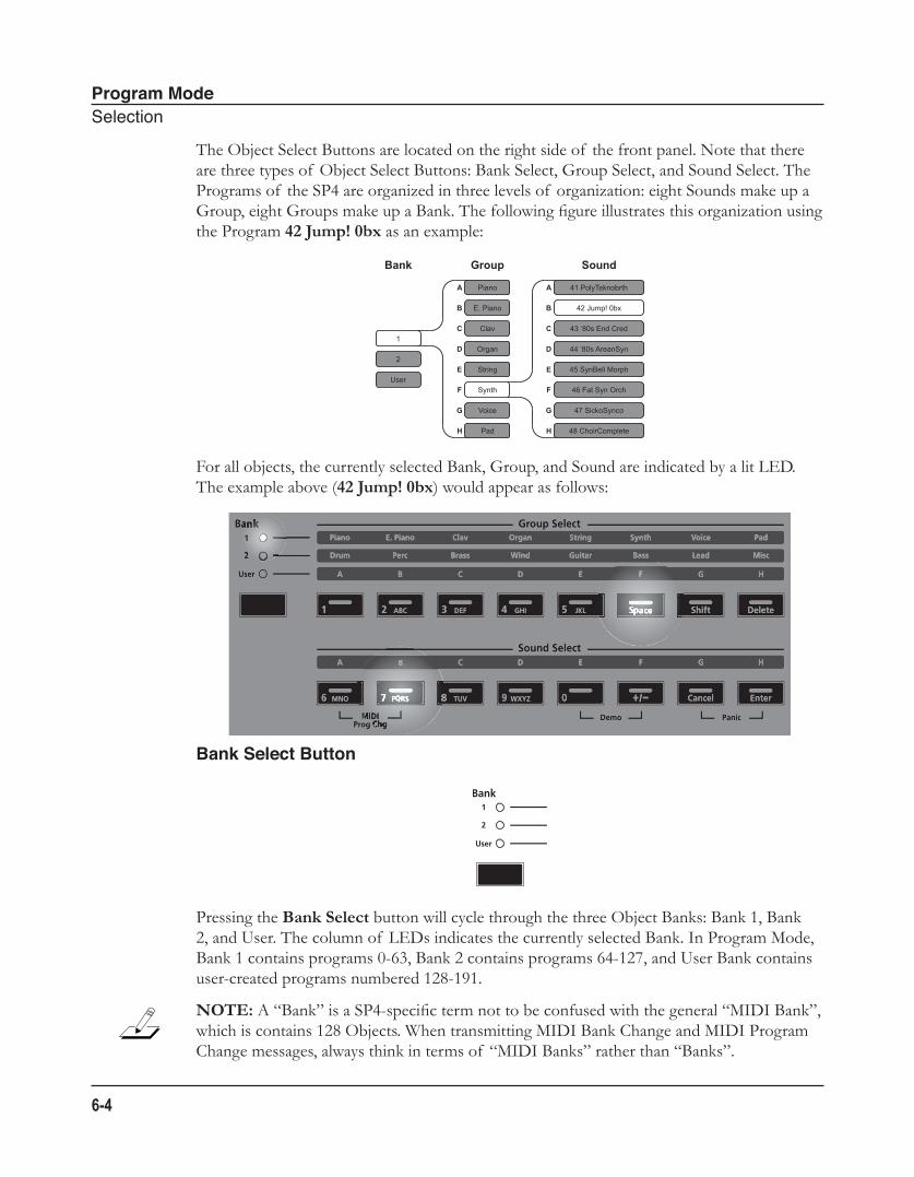
Program ModeSelection
6-4
The Object Select Buttons are located on the right side of the front panel. Note that there are three types of Object Select Buttons: Bank Select, Group Select, and Sound Select. The Programs of the SP4 are organized in three levels of organization: eight Sounds make up a Group, eight Groups make up a Bank. The following figure illustrates this organization using the Program 42 Jump! 0bx as an example:
For all objects, the currently selected Bank, Group, and Sound are indicated by a lit LED. The example above (42 Jump! 0bx) would appear as follows:
Bank Select Button
Pressing the Bank Select button will cycle through the three Object Banks: Bank 1, Bank 2, and User. The column of LEDs indicates the currently selected Bank. In Program Mode, Bank 1 contains programs 0-63, Bank 2 contains programs 64-127, and User Bank contains user-created programs numbered 128-191.
NOTE: A “Bank” is a SP4-specific term not to be confused with the general “MIDI Bank”, which is contains 128 Objects. When transmitting MIDI Bank Change and MIDI Program Change messages, always think in terms of “MIDI Banks” rather than “Banks”.
Bank Group Sound
A
B
C
D
E
F
G
H
A
B
C
D
E
F
G
H
1
2
User
Piano
E. Piano
Clav
Organ
String
Synth
Voice
Pad
41 PolyTeknobrth
42 Jump! 0bx
43 ‘80s End Cred
44 ‘80s AreanSyn
45 SynBell Morph
46 Fat Syn Orch
47 SickoSynco
48 ChoirComplete
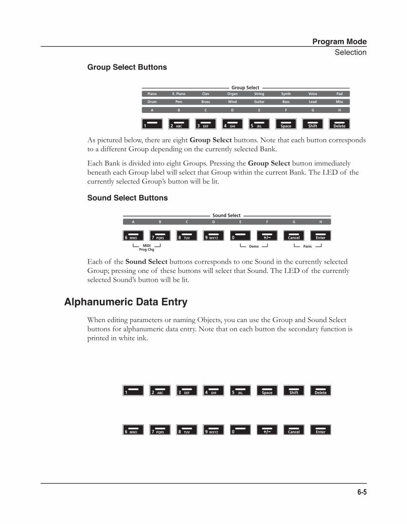
Program ModeSelection
6-5
Group Select Buttons
As pictured below, there are eight Group Select buttons. Note that each button corresponds to a different Group depending on the currently selected Bank.
Each Bank is divided into eight Groups. Pressing the Group Select button immediately beneath each Group label will select that Group within the current Bank. The LED of the currently selected Group’s button will be lit.
Sound Select Buttons
Each of the Sound Select buttons corresponds to one Sound in the currently selected Group; pressing one of these buttons will select that Sound. The LED of the currently selected Sound’s button will be lit.
Alphanumeric Data EntryWhen editing parameters or naming Objects, you can use the Group and Sound Select buttons for alphanumeric data entry. Note that on each button the secondary function is printed in white ink.
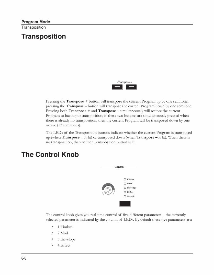
Program ModeTransposition
6-6
Transposition
Pressing the Transpose + button will transpose the current Program up by one semitone; pressing the Transpose – button will transpose the current Program down by one semitone. Pressing both Transpose + and Transpose – simultaneously will restore the current Program to having no transposition; if these two buttons are simultaneously pressed when there is already no transposition, then the current Program will be transposed down by one octave (12 semitones).
The LEDs of the Transposition buttons indicate whether the current Program is transposed up (when Transpose + is lit) or transposed down (when Transpose – is lit). When there is no transposition, then neither Transposition button is lit.
The Control Knob
The control knob gives you real-time control of five different parameters—the currently selected parameter is indicated by the column of LEDs. By default these five parameters are:
• 1 Timbre
• 2 Mod
• 3 Envelope
• 4 Effect
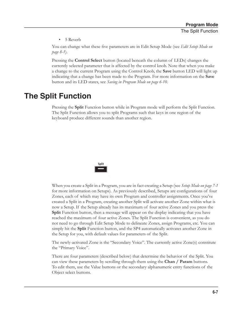
Program ModeTheSplitFunction
6-7
• 5 Reverb
You can change what these five parameters are in Edit Setup Mode (see Edit Setup Mode on page 8-1).
Pressing the Control Select button (located beneath the column of LEDs) changes the currently selected parameter that is affected by the control knob. Note that when you make a change to the current Program using the Control Knob, the Save button LED will light up indicating that a change has been made to the Program. For more information on the Save button and its LED states, see Saving in Program Mode on page 6-10.
The Split FunctionPressing the Split Function button while in Program mode will perform the Split Function. The Split Function allows you to split Programs such that keys in one region of the keyboard produce different sounds than another region.
When you create a Split in a Program, you are in fact creating a Setup (see Setup Mode on page 7-1 for more information on Setups). As previously described, Setups are configurations of four Zones, each of which may have its own Program and controller assignments. Once you’ve created a Split in a Program, creating another Split will activate another Zone within what is now a Setup. If the Setup already has its maximum of four active Zones and you press the Split Function button, then a message will appear on the display indicating that you have reached the maximum of four active Zones. The Split Function is convenient, as you do not need to go through Edit Setup Mode to delineate Zones, assign Programs, etc. You can simply hit the Split Function button, and the SP4 automatically activates another Zone in the Setup for you, with default values for parameters of the Split.
The newly-activated Zone is the “Secondary Voice”. The currently active Zone(s) constitute the “Primary Voice”.
There are four parameters (described below) that determine the behavior of the Split. You can view these parameters by scrolling through them using the Chan / Param buttons. To edit them, use the Value buttons or the secondary alphanumeric entry functions of the Object select buttons.
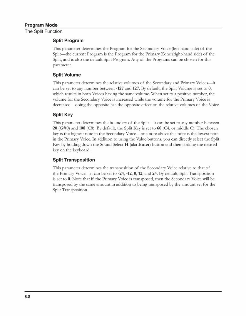
Program ModeTheSplitFunction
6-8
Split ProgramThis parameter determines the Program for the Secondary Voice (left-hand side) of the Split—the current Program is the Program for the Primary Zone (right-hand side) of the Split, and is also the default Split Program. Any of the Programs can be chosen for this parameter.
Split VolumeThis parameter determines the relative volumes of the Secondary and Primary Voices—it can be set to any number between -127 and 127. By default, the Split Volume is set to 0, which results in both Voices having the same volume. When set to a positive number, the volume for the Secondary Voice is increased while the volume for the Primary Voice is decreased—doing the opposite has the opposite effect on the relative volumes of the Voice.
Split KeyThis parameter determines the boundary of the Split—it can be set to any number between 20 (G#0) and 108 (C8). By default, the Split Key is set to 60 (C4, or middle C). The chosen key is the highest note in the Secondary Voice—one note above this note is the lowest note in the Primary Voice. In addition to using the Value buttons, you can directly select the Split Key by holding down the Sound Select H (aka Enter) button and then striking the desired key on the keyboard.
Split TranspositionThis parameter determines the transposition of the Secondary Voice relative to that of the Primary Voice—it can be set to -24, -12, 0, 12, and 24. By default, Split Transposition is set to 0. Note that if the Primary Voice is transposed, then the Secondary Voice will be transposed by the same amount in addition to being transposed by the amount set for the Split Transposition.
Program ModeTheLayerFunction
6-9
The Layer FunctionPressing the Layer Function button while in Program mode will perform the Layer Function. The Layer Function allows you to layer programs and setups such that more than one sound can be produced by striking one key.
When you create a Layer in a Program, you are in fact creating a Setup (see Setup Mode on page 7-1 for more information on Setups). As previously described, Setups are configurations of up to four Zones, each of which may have its own Program and controller assignments. Once you’ve created a Layer in a Program, creating another Layer will create activate another Zone within what is now a Setup. If the current Setup already has its maximum of four active Zones and you press the Layer Function button, then a message will appear on the display indicating that you have reached the maximum of four active Zones. The Layer Function is convenient, as you do not need to go through Edit Setup Mode to delineate Zones, assign Programs, etc. You can simply hit the Layer Function button, and the SP4 automatically activates another Zone in the Setup for you, with default values for parameters of the Layer.
There are three parameters (described below) that determine the behavior of the Layer. You can view these parameters by scrolling through them using the Chan / Param buttons. To edit them, use the Value buttons or the secondary alphanumeric entry functions of the Object select buttons.
Layer ProgramThis parameter determines the program for the Secondary Voice—the current program is the program for the Primary Voice. Any of the programs can be chosen for this parameter.
Layer VolumeThis parameter determines the relative volumes of the Secondary and Primary Voices—it can be set to any number between -127 and 127. By default, the Layer Volume is set to 0, which results in both Voices having the same volume. When set to a positive number, the volume for the Secondary Voice is increased while the volume for the Primary Layer is decreased—doing the opposite has the opposite effect on the relative volumes of the Layers.
Program ModeChangingtheTransmitMIDIChannel
6-10
Layer TranspositionThis parameter determines the transposition of the Secondary Voice relative to that of the Primary Voice—it can be set to -24, -12, 0, 12, and 24. By default, Layer Transposition is set to 0. Note that if the Primary Voice is transposed, then the Secondary Voice will be transposed by the same amount in addition to being transposed by the amount set for the Layer Transposition.
Changing the Transmit MIDI ChannelPressing the Chan / Param Up (̂) or Down (̌) button will change the MIDI transmit channel, incrementing or decrementing it respectively. Pressing both Chan / Param Up (̂) and Down (̌) at the same time will reset the current MIDI channel to 1.
The MIDI channel will be shown briefly in the display before the display changes back to showing the current Program on the selected MIDI transmit channel.
Saving in Program Mode
When you make a change to the current Program using the Control Knob, the Save button LED will light up indicating that a change has been made to the Program. To save the current Program, press the Save button once. The Save button LED will blink to indicate that a save operation is underway, and the User Bank LED will also be lit. If the program is an edited Factory Program (i.e., a Program in Bank 1 or Bank 2), the default save location will be the next available location in the User Bank. If all 64 User Bank slots are taken, then
Program ModeSavinginProgramMode
6-11
the Program is saved in the last slot in the User Bank, overwriting what was previously in that slot. If the current Program is a Program already in the User Bank, then the Program is saved in its current Program slot. At this point, you can rename the new Program using the secondary alphanumeric functions of the Group Select and Sound Select buttons.
When the Save button LED is blinking (which means that you pressed Save, and a save operation is underway), pressing Save again will cause the system to save the current Program to the indicated Group and Sound in the User Bank. If you want to save it to a different location in the User Bank, select the location via the Group Select and Sound Select buttons (or using the Value buttons) before pressing Save again.
Pressing any other button while the Save button is blinking will cancel the save operation.
Program ModeSavinginProgramMode
6-12
Setup ModeAboutSetupMode
7-1
Chapter 7Setup Mode
This chapter will help you familiarize yourself with the features of Setup mode.
Setups are configurations of four Zones (explained below in About Zones), each of which may have its own Program, controller assignments, and MIDI transmit channel. You can have up to 128 different Setups organized in two different banks: Bank 1 (Setups 0-63) and User Bank (Setups 64-127). These provide you respectively with 64 ready-to-play factory Setups and 64 slots for user-created Setups.
About Setup ModeTo enter Setup mode from another mode, press the Setup Function button. While you are in Setup mode, the Setup button’s indicator LED is illuminated. By default, when you enter Setup mode after a start-up of your instrument, Setup 0 will be the current Setup. If you enter Setup mode from another mode, the last selected Setup will be the current Setup.
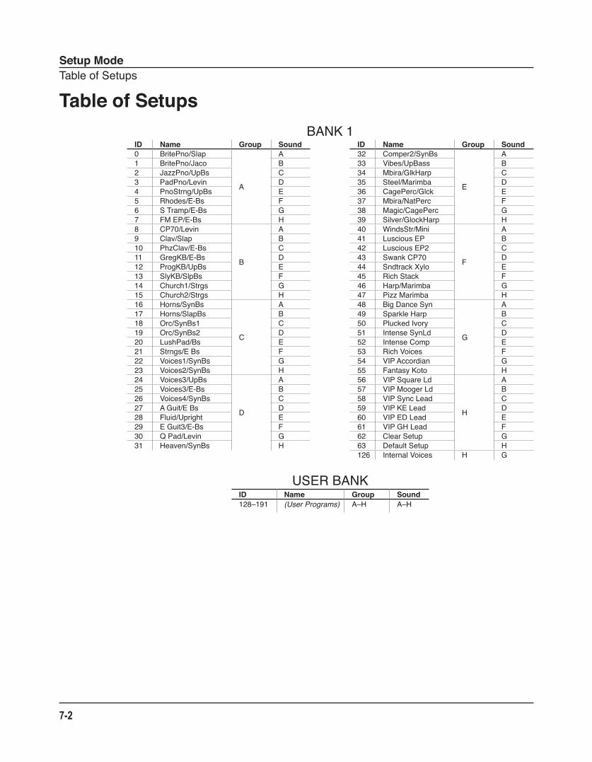
Setup ModeTableofSetups
7-2
Table of SetupsBANK1
ID Name Group Sound ID Name Group Sound0 BritePno/Slap
A
A 32 Comper2/SynBs
E
A1 BritePno/Jaco B 33 Vibes/UpBass B2 JazzPno/UpBs C 34 Mbira/GlkHarp C3 PadPno/Levin D 35 Steel/Marimba D4 PnoStrng/UpBs E 36 CagePerc/Glck E5 Rhodes/E-Bs F 37 Mbira/NatPerc F6 STramp/E-Bs G 38 Magic/CagePerc G7 FMEP/E-Bs H 39 Silver/GlockHarp H8 CP70/Levin
B
A 40 WindsStr/Mini
F
A9 Clav/Slap B 41 LusciousEP B10 PhzClav/E-Bs C 42 LusciousEP2 C11 GregKB/E-Bs D 43 SwankCP70 D12 ProgKB/UpBs E 44 SndtrackXylo E13 SlyKB/SlpBs F 45 RichStack F14 Church1/Strgs G 46 Harp/Marimba G15 Church2/Strgs H 47 PizzMarimba H16 Horns/SynBs
C
A 48 BigDanceSyn
G
A17 Horns/SlapBs B 49 SparkleHarp B18 Orc/SynBs1 C 50 PluckedIvory C19 Orc/SynBs2 D 51 IntenseSynLd D20 LushPad/Bs E 52 IntenseComp E21 Strngs/EBs F 53 RichVoices F22 Voices1/SynBs G 54 VIPAccordian G23 Voices2/SynBs H 55 FantasyKoto H24 Voices3/UpBs
D
A 56 VIPSquareLd
H
A25 Voices3/E-Bs B 57 VIPMoogerLd B26 Voices4/SynBs C 58 VIPSyncLead C27 AGuit/EBs D 59 VIPKELead D28 Fluid/Upright E 60 VIPEDLead E29 EGuit3/E-Bs F 61 VIPGHLead F30 QPad/Levin G 62 ClearSetup G31 Heaven/SynBs H 63 DefaultSetup H
126 InternalVoices H G
USERBANKID Name Group Sound128–191 (User Programs) A–H A–H
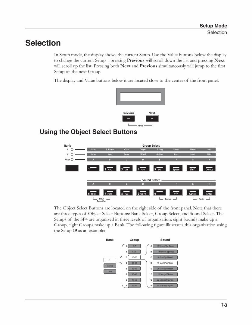
Setup ModeSelection
7-3
SelectionIn Setup mode, the display shows the current Setup. Use the Value buttons below the display to change the current Setup—pressing Previous will scroll down the list and pressing Next will scroll up the list. Pressing both Next and Previous simultaneously will jump to the first Setup of the next Group.
The display and Value buttons below it are located close to the center of the front panel.
Using the Object Select Buttons
The Object Select Buttons are located on the right side of the front panel. Note that there are three types of Object Select Buttons: Bank Select, Group Select, and Sound Select. The Setups of the SP4 are organized in three levels of organization: eight Sounds make up a Group, eight Groups make up a Bank. The following figure illustrates this organization using the Setup 19 as an example:
Bank Group Sound
A
B
C
D
E
F
G
H
A
B
C
D
E
F
G
H
1
(none)
User
0-7
8-15
16-23
24-31
32-39
40-47
48-55
56-63
16 Horns/SynBass
17 Horns/SlapBass
18 Orc/SynBass1
19 LushPad/Bass
20 Orc/SynBass4
21 Strngs/EBass
22 Voices1/SynBs
23 Voices2/SynBs
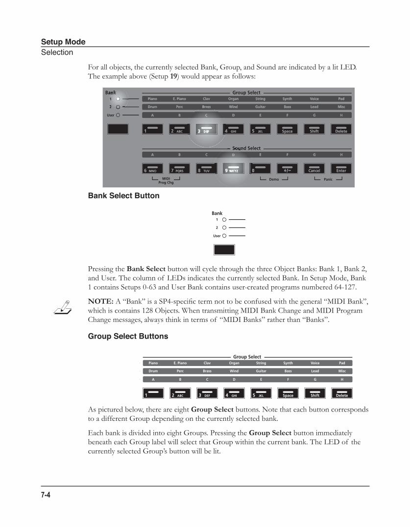
Setup ModeSelection
7-4
For all objects, the currently selected Bank, Group, and Sound are indicated by a lit LED. The example above (Setup 19) would appear as follows:
Bank Select Button
Pressing the Bank Select button will cycle through the three Object Banks: Bank 1, Bank 2, and User. The column of LEDs indicates the currently selected Bank. In Setup Mode, Bank 1 contains Setups 0-63 and User Bank contains user-created programs numbered 64-127.
NOTE: A “Bank” is a SP4-specific term not to be confused with the general “MIDI Bank”, which is contains 128 Objects. When transmitting MIDI Bank Change and MIDI Program Change messages, always think in terms of “MIDI Banks” rather than “Banks”.
Group Select Buttons
As pictured below, there are eight Group Select buttons. Note that each button corresponds to a different Group depending on the currently selected bank.
Each bank is divided into eight Groups. Pressing the Group Select button immediately beneath each Group label will select that Group within the current bank. The LED of the currently selected Group’s button will be lit.
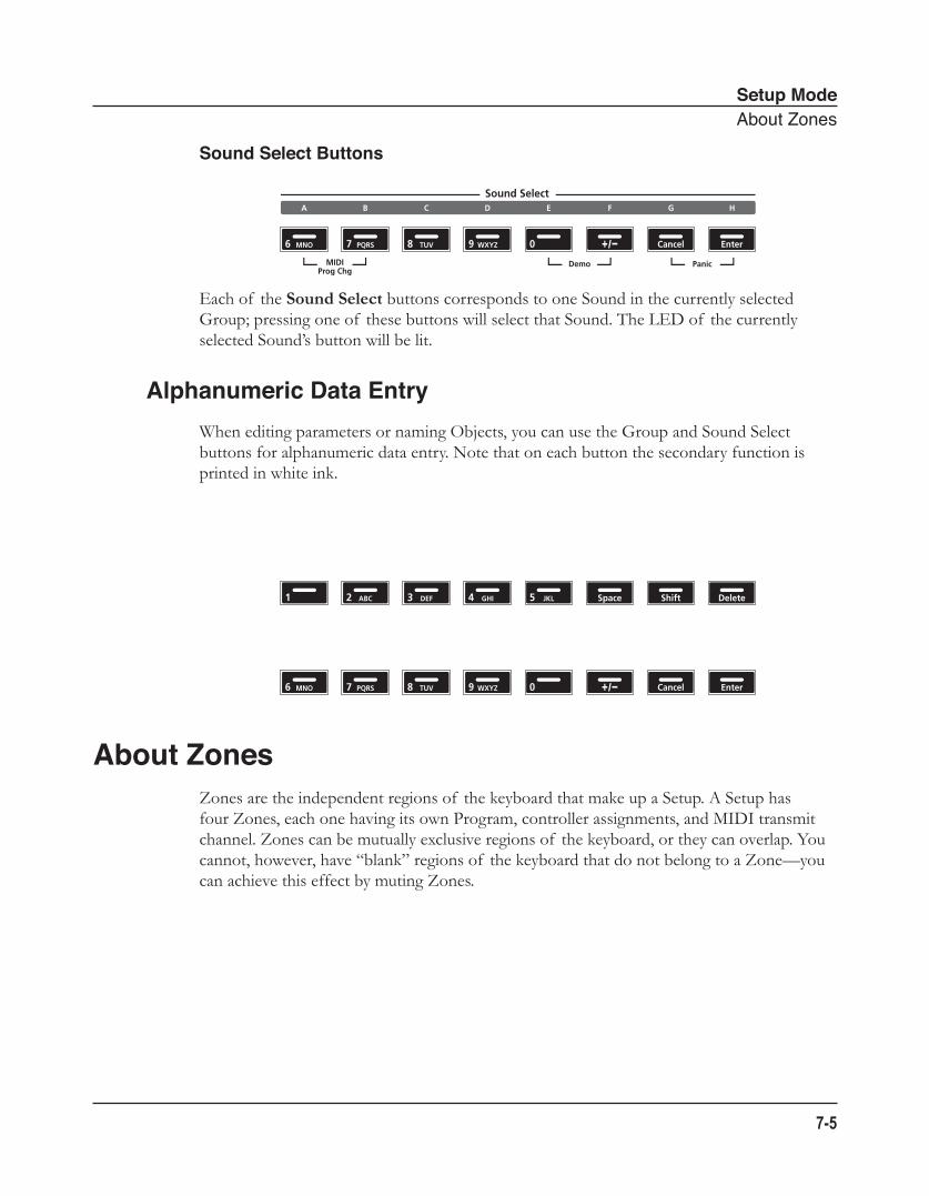
Setup ModeAboutZones
7-5
Sound Select Buttons
Each of the Sound Select buttons corresponds to one Sound in the currently selected Group; pressing one of these buttons will select that Sound. The LED of the currently selected Sound’s button will be lit.
Alphanumeric Data EntryWhen editing parameters or naming Objects, you can use the Group and Sound Select buttons for alphanumeric data entry. Note that on each button the secondary function is printed in white ink.
About ZonesZones are the independent regions of the keyboard that make up a Setup. A Setup has four Zones, each one having its own Program, controller assignments, and MIDI transmit channel. Zones can be mutually exclusive regions of the keyboard, or they can overlap. You cannot, however, have “blank” regions of the keyboard that do not belong to a Zone—you can achieve this effect by muting Zones.
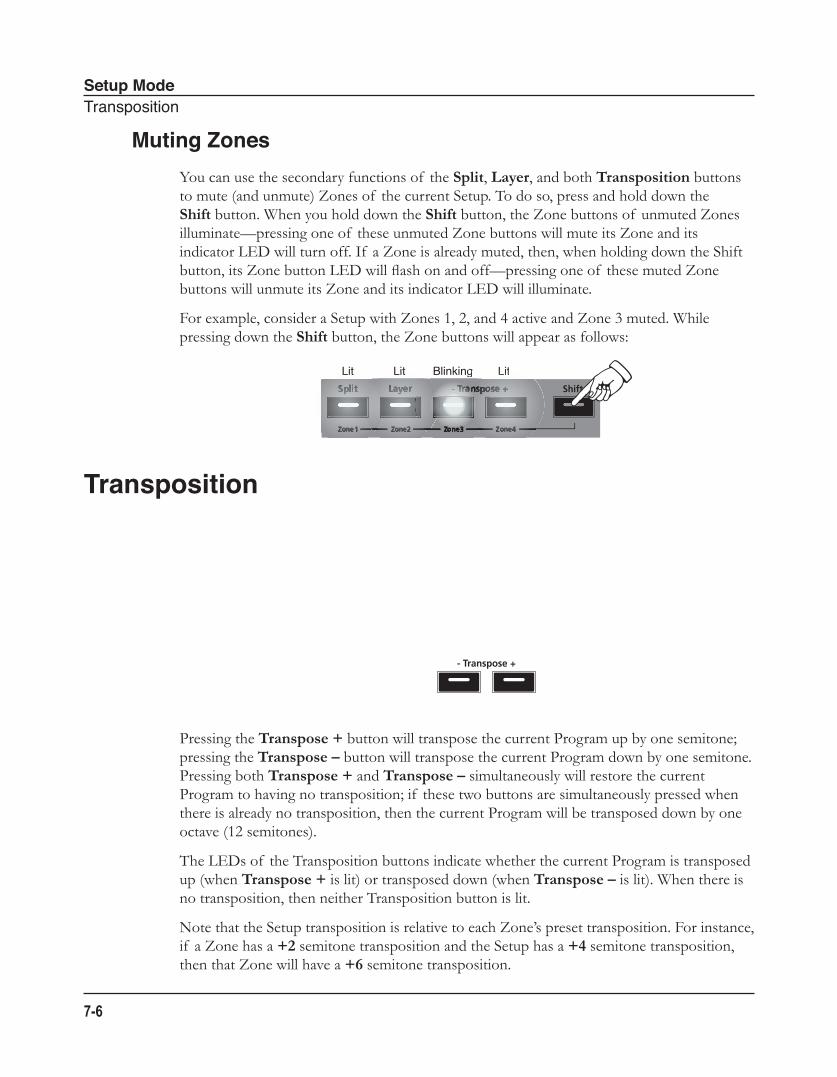
Setup ModeTransposition
7-6
Muting ZonesYou can use the secondary functions of the Split, Layer, and both Transposition buttons to mute (and unmute) Zones of the current Setup. To do so, press and hold down the Shift button. When you hold down the Shift button, the Zone buttons of unmuted Zones illuminate—pressing one of these unmuted Zone buttons will mute its Zone and its indicator LED will turn off. If a Zone is already muted, then, when holding down the Shift button, its Zone button LED will flash on and off—pressing one of these muted Zone buttons will unmute its Zone and its indicator LED will illuminate.
For example, consider a Setup with Zones 1, 2, and 4 active and Zone 3 muted. While pressing down the Shift button, the Zone buttons will appear as follows:
Transposition
Pressing the Transpose + button will transpose the current Program up by one semitone; pressing the Transpose – button will transpose the current Program down by one semitone. Pressing both Transpose + and Transpose – simultaneously will restore the current Program to having no transposition; if these two buttons are simultaneously pressed when there is already no transposition, then the current Program will be transposed down by one octave (12 semitones).
The LEDs of the Transposition buttons indicate whether the current Program is transposed up (when Transpose + is lit) or transposed down (when Transpose – is lit). When there is no transposition, then neither Transposition button is lit.
Note that the Setup transposition is relative to each Zone’s preset transposition. For instance, if a Zone has a +2 semitone transposition and the Setup has a +4 semitone transposition, then that Zone will have a +6 semitone transposition.
Lit Lit LitBlinking LitLitLitLitBlinking
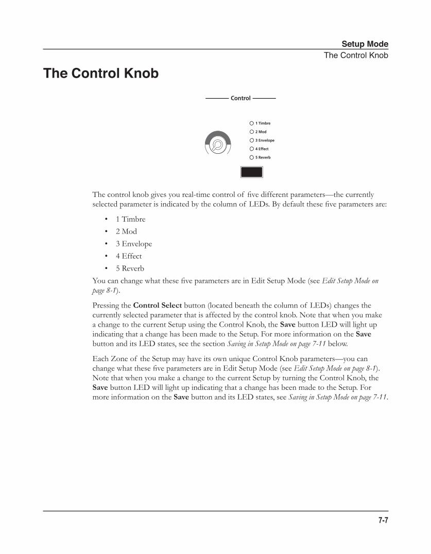
Setup ModeTheControlKnob
7-7
The Control Knob
The control knob gives you real-time control of five different parameters—the currently selected parameter is indicated by the column of LEDs. By default these five parameters are:
• 1 Timbre
• 2 Mod
• 3 Envelope
• 4 Effect
• 5 Reverb
You can change what these five parameters are in Edit Setup Mode (see Edit Setup Mode on page 8-1).
Pressing the Control Select button (located beneath the column of LEDs) changes the currently selected parameter that is affected by the control knob. Note that when you make a change to the current Setup using the Control Knob, the Save button LED will light up indicating that a change has been made to the Setup. For more information on the Save button and its LED states, see the section Saving in Setup Mode on page 7-11 below.
Each Zone of the Setup may have its own unique Control Knob parameters—you can change what these five parameters are in Edit Setup Mode (see Edit Setup Mode on page 8-1). Note that when you make a change to the current Setup by turning the Control Knob, the Save button LED will light up indicating that a change has been made to the Setup. For more information on the Save button and its LED states, see Saving in Setup Mode on page 7-11.
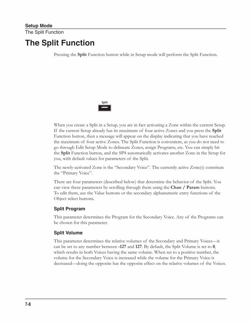
Setup ModeTheSplitFunction
7-8
The Split FunctionPressing the Split Function button while in Setup mode will perform the Split Function.
When you create a Split in a Setup, you are in fact activating a Zone within the current Setup. If the current Setup already has its maximum of four active Zones and you press the Split Function button, then a message will appear on the display indicating that you have reached the maximum of four active Zones. The Split Function is convenient, as you do not need to go through Edit Setup Mode to delineate Zones, assign Programs, etc. You can simply hit the Split Function button, and the SP4 automatically activates another Zone in the Setup for you, with default values for parameters of the Split.
The newly-activated Zone is the “Secondary Voice”. The currently active Zone(s) constitute the “Primary Voice”.
There are four parameters (described below) that determine the behavior of the Split. You can view these parameters by scrolling through them using the Chan / Param buttons. To edit them, use the Value buttons or the secondary alphanumeric entry functions of the Object select buttons.
Split ProgramThis parameter determines the Program for the Secondary Voice. Any of the Programs can be chosen for this parameter.
Split VolumeThis parameter determines the relative volumes of the Secondary and Primary Voices—it can be set to any number between -127 and 127. By default, the Split Volume is set to 0, which results in both Voices having the same volume. When set to a positive number, the volume for the Secondary Voice is increased while the volume for the Primary Voice is decreased—doing the opposite has the opposite effect on the relative volumes of the Voices.
Setup ModeTheLayerFunction
7-9
Split KeyThis parameter determines the boundary of the Split—it can be set to any number between 20 (G#0) and 108 (C8). By default, the Split Key is set to 60 (C4, or middle C). The chosen key is the highest note in the Secondary Voice—one note above this note is the lowest note in the Primary Voice. In addition to using the Value buttons, you can directly select the Split Key by holding down the Sound Select H (aka Enter) button and then striking the desired key on the keyboard.
Split TranspositionThis parameter determines the transposition of the Secondary Voice relative to that of the Primary Voice—it can be set to -24, -12, 0, 12, and 24. By default, Split Transposition is set to 0. Note that if the Primary Voice is transposed, then the Secondary Voice will be transposed by the same amount in addition to being transposed by the amount set for the Split Transposition.
The Layer FunctionPressing the Layer Function button while in Setup mode will perform the Layer Function.
When you create a Layer in a Setup, you are in fact activating a Zone within the current Setup. If the current Setup already has its maximum of four active Zones and you press the Layer Function button, then a message will appear on the display indicating that you have reached the maximum of four active Zones. The Layer Function is convenient, as you do not need to go through Edit Setup Mode to delineate Zones, assign Programs, etc. You can simply hit the Layer Function button, and the SP4 automatically activates another Zone in the Setup for you, with default values for parameters of the Layer.
The newly-activated Zone is the “Secondary Voice”. The currently active Zone(s) constitute the “Primary Voice”.
There are three parameters (described below) that determine the behavior of the Layer. You can view these parameters by scrolling through them using the Chan / Param buttons. To edit them, use the Value buttons or the secondary alphanumeric entry functions of the Object select buttons.
Setup ModeChangingtheTransmitMIDIChannel
7-10
Layer ProgramThis parameter determines the program for the Secondary Voice. Any of the Programs can be chosen for this parameter.
Layer VolumeThis parameter determines the relative volumes of the Secondary and Primary Voices—it can be set to any number between -127 and 127. By default, the Layer Volume is set to 0, which results in both Voices having the same volume. When set to a positive number, the volume for the Secondary Voice is increased while the volume for the Primary Voice is decreased—doing the opposite has the opposite effect on the relative volumes of the Voices.
Layer TranspositionThis parameter determines the transposition of the Secondary Voice relative to that of the Primary Voice—it can be set to -24, -12, 0, 12, and 24. By default, Layer Transposition is set to 0. Note that if the Primary Voice is transposed, then the Secondary Voice will be transposed by the same amount in addition to being transposed by the amount set for the Layer Transposition.
Changing the Transmit MIDI ChannelPressing the Chan / Param Up (̂) or Down (̌) button will change the MIDI transmit channel, incrementing or decrementing it respectively. Pressing both Chan / Param Up (̂) and Down (̌) at the same time will reset the current MIDI channel to 1.
The MIDI channel will be shown briefly in the display before the display changes back to showing the current Program on the selected MIDI transmit channel.
Setup ModeSavinginSetupMode
7-11
Saving in Setup Mode
When you make a change to the current Setup using the Control Knob, the Save button LED will light up indicating that a change has been made to the Setup. To save the current Setup, press the Save button once. The Save button LED will blink to indicate that a save operation is underway, and the User Bank LED will also be lit. If the Setup is an edited Factory Setup (i.e., a Setup in Bank 1), the default save location will be the next available location in the User Bank. If all 64 User Bank slots are taken, then the Setup is saved in the last slot in the User Bank, overwriting what was previously in that slot. If the current Setup is a Setup already in the User Bank, then the Setup is saved in its current Setup slot. At this point, you can rename the new Setup using the secondary alphanumeric functions of the Group Select and Sound Select buttons.
When the Save button LED is blinking (which means that you pressed Save, and a save operation is underway), pressing Save again will cause the system to save the current Setup to the indicated Group and Sound in the User Bank. If you want to save it to a different location in the User Bank, select the location via the Group Select and Sound Select buttons (or using the Value buttons) before pressing Save again.
Pressing any other button while the Save button is blinking will cancel the save operation.
Setup ModeSavinginSetupMode
7-12
Edit Setup ModeAboutEditSetupMode
8-1
Chapter 8Edit Setup Mode
This chapter will help you familiarize yourself with the features of Edit Setup Mode
About Edit Setup ModeNOTE: Before you read this chapter, be sure to read Setup Mode on page 7-1 for a full description of Setups.
Edit Setup mode allows you to edit and create Setups—it gives you access to a Setup’s common parameters and Zone-specific parameters. In this mode, you can customize the Program, controller assignments, and MIDI transmit channel (in addition to many other parameters) of the Zones in a Setup. Any Setup edited or created in Edit Setup mode is saved to one of the 64 User Bank slots.
To enter Edit Setup mode from another mode, press the Edit Setup Function button. While you are in Edit Setup mode, the Edit Setup button’s indicator LED is illuminated.
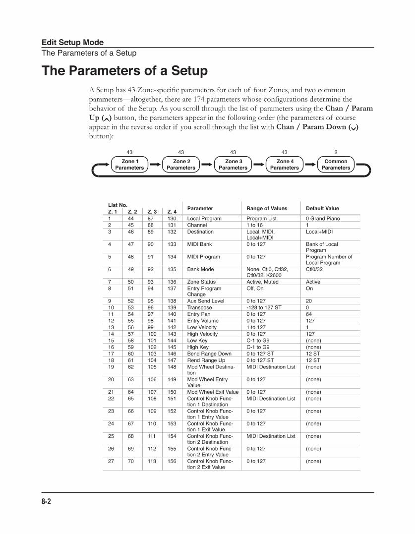
Edit Setup ModeTheParametersofaSetup
8-2
The Parameters of a SetupA Setup has 43 Zone-specific parameters for each of four Zones, and two common parameters—altogether, there are 174 parameters whose configurations determine the behavior of the Setup. As you scroll through the list of parameters using the Chan / Param Up (̂) button, the parameters appear in the following order (the parameters of course appear in the reverse order if you scroll through the list with Chan / Param Down (̌) button):
List No. Parameter Range of Values Default ValueZ. 1 Z. 2 Z. 3 Z. 41 44 87 130 LocalProgram ProgramList 0GrandPiano2 45 88 131 Channel 1to16 13 46 89 132 Destination Local,MIDI,
Local+MIDILocal+MIDI
4 47 90 133 MIDIBank 0to127 BankofLocalProgram
5 48 91 134 MIDIProgram 0to127 ProgramNumberofLocalProgram
6 49 92 135 BankMode None,Ctl0,Ctl32,Ctl0/32,K2600
Ctl0/32
7 50 93 136 ZoneStatus Active,Muted Active8 51 94 137 EntryProgram
ChangeOff,On On
9 52 95 138 AuxSendLevel 0to127 2010 53 96 139 Transpose -128to127ST 011 54 97 140 EntryPan 0to127 6412 55 98 141 EntryVolume 0to127 12713 56 99 142 LowVelocity 1to127 114 57 100 143 HighVelocity 0to127 12715 58 101 144 LowKey C-1toG9 (none)16 59 102 145 HighKey C-1toG9 (none)17 60 103 146 BendRangeDown 0to127ST 12ST18 61 104 147 RendRangeUp 0to127ST 12ST19 62 105 148 ModWheelDestina-
tionMIDIDestinationList (none)
20 63 106 149 ModWheelEntryValue
0to127 (none)
21 64 107 150 ModWheelExitValue 0to127 (none)22 65 108 151 ControlKnobFunc-
tion1DestinationMIDIDestinationList (none)
23 66 109 152 ControlKnobFunc-tion1EntryValue
0to127 (none)
24 67 110 153 ControlKnobFunc-tion1ExitValue
0to127 (none)
25 68 111 154 ControlKnobFunc-tion2Destination
MIDIDestinationList (none)
26 69 112 155 ControlKnobFunc-tion2EntryValue
0to127 (none)
27 70 113 156 ControlKnobFunc-tion2ExitValue
0to127 (none)
Zone 1Parameters
Zone 2Parameters
Zone 3Parameters
Zone 4Parameters
CommonParameters
43 43 43 43 2
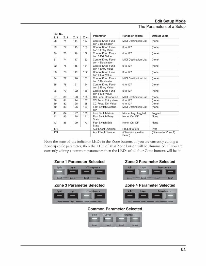
Edit Setup ModeTheParametersofaSetup
8-3
List No. Parameter Range of Values Default ValueZ. 1 Z. 2 Z. 3 Z. 428 71 114 157 ControlKnobFunc-
tion3DestinationMIDIDestinationList (none)
29 72 115 158 ControlKnobFunc-tion3EntryValue
0to127 (none)
30 73 116 159 ControlKnobFunc-tion3ExitValue
0to127 (none)
31 74 117 160 ControlKnobFunc-tion4Destination
MIDIDestinationList (none)
32 75 118 161 ControlKnobFunc-tion4EntryValue
0to127 (none)
33 76 119 162 ControlKnobFunc-tion4ExitValue
0to127 (none)
34 77 120 163 ControlKnobFunc-tion5Destination
MIDIDestinationList (none)
35 78 121 164 ControlKnobFunc-tion5EntryValue
0to127 (none)
36 79 122 165 ControlKnobFunc-tion5ExitValue
0to127 (none)
37 80 123 166 CCPedalDestination MIDIDestinationList (none)38 81 124 167 CCPedalEntryValue 0to127 (none)39 82 125 168 CCPedalExitValue 0to127 (none)40 83 126 169 FootSwitchDestina-
tionMIDIDestinationList (none)
41 84 127 170 FootSwitchMode Momentary,Toggled Toggled42 85 128 171 FootSwitchEntry
StateNone,On,Off None
43 86 129 172 FootSwitchExitState
None,On,Off None
173 AuxEffectOverride Prog,0to999 Prog174 AuxEffectChannel (Channelsusedin
Setup)(ChannelofZone1)
Note the state of the indicator LEDs in the Zone buttons. If you are currently editing a Zone-specific parameter, then the LED of that Zone button will be illuminated. If you are currently editing a common parameter, then the LEDs of all four Zone buttons will be lit.
Common Parameter Selected
Zone 4 Parameter SelectedZone 3 Parameter Selected
Zone 2 Parameter SelectedZone 1 Parameter Selected
Edit Setup ModeTheZone-specificParameters
8-4
To edit the currently selected parameter, simply use the Next and Previous Value buttons below the display. Pressing both Value buttons simultaneously will jump to a different value depending on the parameter—the jump value is mentioned in each of the parameter descriptions below. Additionally, you can use the secondary numeric functions of the Group Select and Sound Select buttons.
The Zone-specific ParametersEach of the four Zones in Setup has 43 parameters that determine its behavior. Since the Zones of a Setup are independent of each other, changing a parameter for a certain Zone will not affect the parameters of any other Zone.
Local ProgramThe Local Program parameter determines the Program to be loaded for the currently selected Zone. You can set this parameter to any of the 192 Programs (0-191). Note that the display shows only the Program number but not the name. Pressing both Value buttons simultaneously will set this parameter to 0 (0 Grand Piano)
Editing this parameter also changes the MIDI Bank and MIDI Program parameters, described below.
ChannelThe Channel parameter determines the MIDI transmit channel for the currently selected Zone. You can set this parameter to any of the 16 MIDI channels (1-16). Pressing both Value buttons simultaneously will set this parameter to 1.
DestinationThe Destination parameter determines whether MIDI data generated by the currently selected Zone is sent to the SP4 sound engine, through the MIDI OUT port, or both. You can set this parameter to any of the three destinations for this parameter:
Local MIDI data is sent only to the SP4 sound engine. The MIDI OUT port is disabled.
MIDI MIDI data is sent only through the MIDI OUT port. The sounds of the current Zone are disabled.
Local+MIDI MIDI data is sent both to the SP4 sound engine and through the MIDI OUT port.
Select the desired destination depending on your needs. If you want to play the SP4, but
Edit Setup ModeTheZone-specificParameters
8-5
not send any MIDI information to other MIDI instruments, then select Local. If you want to use the SP4 strictly as a MIDI controller for the other modules in your MIDI chain, then select MIDI. If you want to make use of the SP4’s sounds as well as use it as a MIDI controller, then select Local+MIDI.
Pressing both Value buttons simultaneously will set this parameter to Local+MIDI.
MIDI BankThe MIDI Bank parameter determines the MIDI Bank change message that the currently selected Zone sends when the Setup is loaded. You can set this parameter to a MIDI Bank change message from 0 to 127.
When using the SP4 as a MIDI controller, sending a MIDI Bank change message (along with a MIDI program change message) when a Setup is loaded ensures that the Program loaded on the other sound modules in your MIDI chain is the Program that you want. For example, if you’ve configured a Setup to work in a specific way with Program 32 in Bank 5 of a connected sound module, then set MIDI Bank to 5 and MIDI Program to 32. This way, whenever you load this Setup, the sound module will automatically load Program 32 in Bank 5.
Pressing both Value buttons simultaneously will set this parameter to the Bank number of the currently select Local Program.
NOTE: When you change the Local Program parameter, the MIDI Bank and MIDI Program parameters will automatically change to match the Bank and Program numbers of the Program that you select for Local Program. For example, if you choose Program 178, then MIDI Bank will change to 1 and MIDI Program will change to 50.
NOTE: A “Bank” is a SP4-specific term not to be confused with the general “MIDI Bank”, which is contains 128 Objects. When transmitting MIDI Bank Change and MIDI Program Change messages, always think in terms of “MIDI Banks” rather than “Banks”.
Differing Program NumbersIf the programs on your connected sound module are organized by MIDI Bank with each program number being between 0 and 127, then use the following formula to determine what number to enter for the MIDI Program Change Function:
[MIDI Bank number] * 128 + [program number] - 1
So for example, if you want to send to a MIDI Program Change message for Program 83 in MIDI Bank 4, you would enter the number 594—this number is equal to 4 * 128 + 83 - 1.
Edit Setup ModeTheZone-specificParameters
8-6
If the programs on your connected sound module are organized by MIDI Bank with each program number being between 1 and 128, then use the following formula to determine what number to enter in MIDI Program Change mode:
[MIDI Bank number] * 128 + [program number]
So for example, if you want to send to a MIDI Program Change message for Program 83 in MIDI Bank 4, you would enter the number 595—this number is equal to 4 * 128 + 83.
MIDI ProgramThe MIDI Program parameter determines the MIDI Program change message that the currently selected Zone sends when the Setup is loaded. You can set this parameter to a MIDI Program change message from 0 to 127.
When using the SP4 as a MIDI controller, sending a MIDI program change message (along with a MIDI bank change message) when a Setup is loaded ensures that the Program loaded on the other sound modules in your MIDI chain is the Program that you want. For example, if you’ve configured a Setup to work in a specific way with Program 32 in Bank 5 of a connected sound module, then set MIDI Bank to 5 and MIDI Program to 32. This way, whenever you load this Setup, the sound module will automatically load Program 32 in Bank 5.
Pressing both Value buttons simultaneously will set this parameter to the Program number of the currently select Local Program.
NOTE: When you change the Local Program parameter, the MIDI Bank and MIDI Program parameters will automatically change to match the Bank and Program numbers of the Program that you select for Local Program. For example, if you choose Program 178, then MIDI Bank will change to 1 and MIDI Program will change to 50.
NOTE: A “Bank” is a SP4-specific term not to be confused with the general “MIDI Bank”, which is contains 128 Objects. When transmitting MIDI Bank Change and MIDI Program Change messages, always think in terms of “MIDI Banks” rather than “Banks”.
Differing Program NumbersIf the programs on your connected sound module are organized by MIDI Bank with each program number being between 0 and 127, then use the following formula to determine what number to enter for the MIDI Program Change Function:
[MIDI Bank number] * 128 + [program number] - 1
So for example, if you want to send to a MIDI Program Change message for Program 83 in MIDI Bank 4, you would enter the number 594—this number is equal to 4 * 128 + 83 - 1.
Edit Setup ModeTheZone-specificParameters
8-7
If the programs on your connected sound module are organized by MIDI Bank with each program number being between 1 and 128, then use the following formula to determine what number to enter in MIDI Program Change mode:
[MIDI Bank number] * 128 + [program number]
So for example, if you want to send to a MIDI Program Change message for Program 83 in MIDI Bank 4, you would enter the number 595—this number is equal to 4 * 128 + 83.
Bank ModeThe Bank Mode parameter determines the controller number with which MIDI Bank change messages are transmitted. For MIDI Bank change messages, various manufacturers have chosen different MIDI controller numbers. Most have chosen 0, 32, or both. In the case of the Kurzweil K2600, it has its own unique controller number that it responds to.
You can set this parameter to any of the five controller IDs:
None MIDI Bank change messages are disabled.
Ctl0 MIDI Bank change messages are sent with controller number 0.
Ctl32 MIDI Bank change messages are sent with controller number 32.
Ctl0/32 MIDI Bank change messages are sent with both controller numbers 0 and 32.
K2600 MIDI Bank change messages are sent with the Kurzweil K2600 Bank change controller number.
Pressing both Value buttons simultaneously will set this parameter to Ctl0/32.
Zone StatusThe Zone Status parameter determines whether the currently selected Zone is active or muted. You can set this parameter to either of two states: Active or Muted. Pressing both Value buttons simultaneously will set this parameter to Active.
Entry Program ChangeThe Entry Program Change parameter determines whether or not the currently selected Zone can send a MIDI Program change message when the Setup is loaded. You can set this parameter to either Off or On. When set to On, the Zone will send a MIDI Program change message with the Program specified for the MIDI Program parameter (described above). Pressing both Value buttons simultaneously will set this parameter to On.
Edit Setup ModeTheZone-specificParameters
8-8
Aux Send LevelThe Aux Send Level parameter determines the send level for the auxiliary effects of the currently selected Zone. You can select any level from 0 to 127. Pressing both Value buttons simultaneously will set this parameter to 20.
For a description of the auxiliary effects of a Setup, see About Auxiliary Effects on page 8-14 and Common Parameters on page 8-14.
TransposeThe Transpose parameter determines the transposition for the currently selected Zone. You can set this to any value from -128 semitones to 127 semitones. Pressing both Value buttons simultaneously will set this parameter to 0.
Entry PanThe Entry Pan parameter determines the Pan MIDI message that the currently selected Zone sends when the Setup is loaded. You can set this parameter to any pan setting from 0 (full left pan) to 127 (full right pan). For zero panning, select 64 for this parameter. Pressing both Value buttons simultaneously will set this parameter to 64.
Entry VolumeThe Entry Volume parameter determines the Volume MIDI message that the currently selected Zone sends when the Setup is loaded. You can set this parameter to any volume setting from 0 to 127. Pressing both Value buttons simultaneously will set this parameter to 127.
Low VelocityThe Low Velocity parameter determines the lowest velocity that a keystroke must have in order to trigger a note in the currently selected Zone. You can set this parameter to any velocity between 1 and 127. Pressing both Value buttons simultaneously will set this parameter to 1.
If, for example, you set Low Velocity to 20, then only keystrokes with velocities of 20 or above will trigger a note. Keystrokes with velocities lower than 20 will not trigger a note.
Edit Setup ModeTheZone-specificParameters
8-9
High VelocityThe High Velocity parameter determines the highest velocity that a keystroke must have in order to trigger a note in the currently selected Zone. You can set this parameter to any velocity between 0 and 127. Pressing both Value buttons simultaneously will set this parameter to 127.
If, for example, you set High Velocity to 80, then only keystrokes with velocities of 80 or below will trigger a note. Keystrokes with velocities higher than 80 will not trigger a note.
Low KeyThe Low Key parameter determines the lower boundary of the currently selected Zone. You can set this parameter to any note from C-1 to G9. Pressing both Value buttons simultaneously will set this parameter to C-1.
If, for example, you set Low Key to C4, then only keys at or above C4 will trigger a note for the currently selected Zone. Keys below C4 will not trigger a note.
High KeyThe High Key parameter determines the higher boundary of the currently selected Zone. You can set this parameter to any note from C-1 to G9. Pressing both Value buttons simultaneously will set this parameter to G9.
If, for example, you set High Key to C4, then only keys at or below C4 will trigger a note for the currently selected Zone. Keys above C4 will not trigger a note.
Bend Range DownThe Bend Range Down parameter determines the lower bend of the Pitch Wheel. You can set this parameter to any value between 0 semitones and 127 semitones, or to Prog, which uses the Bend Range of the currently selected Program for the Zone. Pressing both Value buttons simultaneously will set this parameter to 12 semitones.
Bend Range UpThe Bend Range Up parameter determines the upper bend of the Pitch Wheel. You can set this parameter to any value between 0 semitones and 127 semitones, or to Prog, which uses the Bend Range of the currently selected Program for the Zone. Pressing both Value buttons simultaneously will set this parameter to 2 semitones.
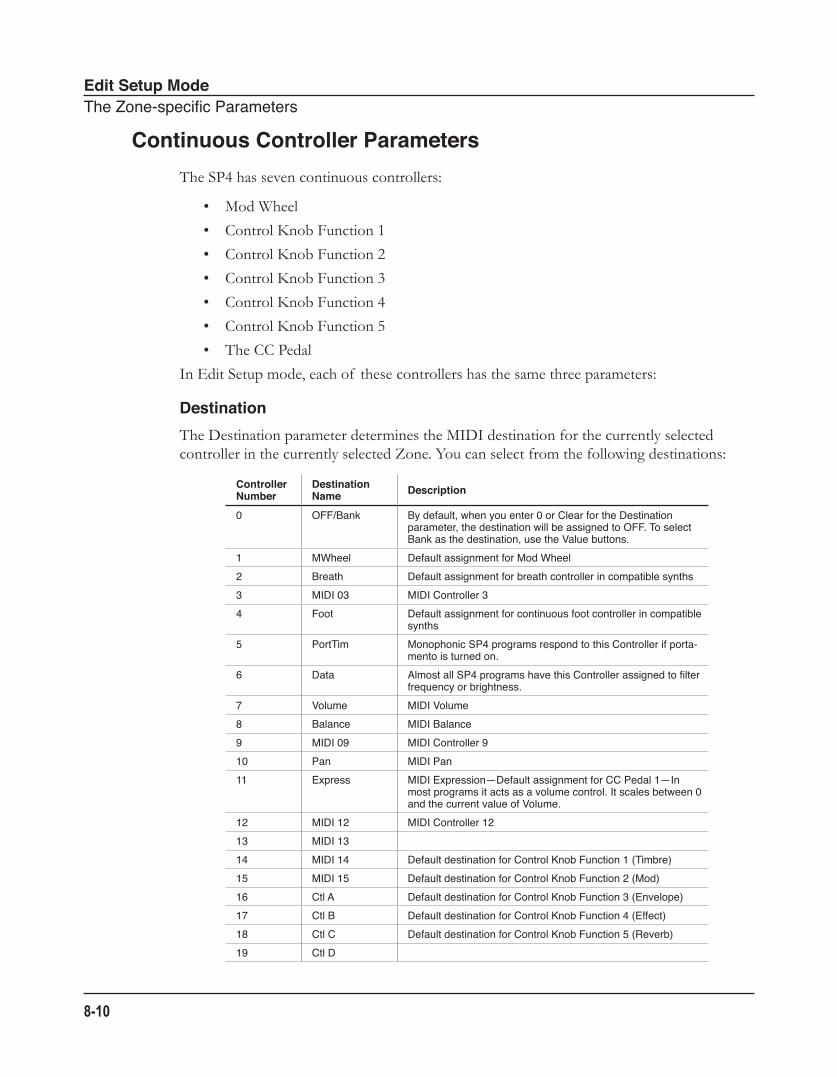
Edit Setup ModeTheZone-specificParameters
8-10
Continuous Controller ParametersThe SP4 has seven continuous controllers:
• Mod Wheel
• Control Knob Function 1
• Control Knob Function 2
• Control Knob Function 3
• Control Knob Function 4
• Control Knob Function 5
• The CC Pedal
In Edit Setup mode, each of these controllers has the same three parameters:
DestinationThe Destination parameter determines the MIDI destination for the currently selected controller in the currently selected Zone. You can select from the following destinations:
Controller Number
Destination Name Description
0 OFF/Bank Bydefault,whenyouenter0orClearfortheDestinationparameter,thedestinationwillbeassignedtoOFF.ToselectBankasthedestination,usetheValuebuttons.
1 MWheel DefaultassignmentforModWheel2 Breath Defaultassignmentforbreathcontrollerincompatiblesynths3 MIDI03 MIDIController34 Foot Defaultassignmentforcontinuousfootcontrollerincompatible
synths5 PortTim MonophonicSP4programsrespondtothisControllerifporta-
mentoisturnedon.6 Data AlmostallSP4programshavethisControllerassignedtofilter
frequencyorbrightness.7 Volume MIDIVolume8 Balance MIDIBalance9 MIDI09 MIDIController910 Pan MIDIPan11 Express MIDIExpression—DefaultassignmentforCCPedal1—In
mostprogramsitactsasavolumecontrol.Itscalesbetween0andthecurrentvalueofVolume.
12 MIDI12 MIDIController1213 MIDI1314 MIDI14 DefaultdestinationforControlKnobFunction1(Timbre)15 MIDI15 DefaultdestinationforControlKnobFunction2(Mod)16 CtlA DefaultdestinationforControlKnobFunction3(Envelope)17 CtlB DefaultdestinationforControlKnobFunction4(Effect)18 CtlC DefaultdestinationforControlKnobFunction5(Reverb)19 CtlD
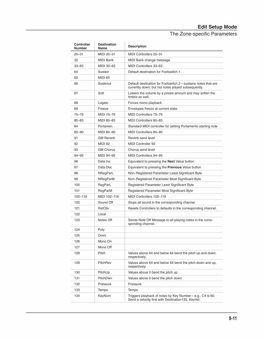
Edit Setup ModeTheZone-specificParameters
8-11
Controller Number
Destination Name Description
20–31 MIDI20–31 MIDIControllers20–3132 MIDIBank MIDIBankchangemessage33–63 MIDI33–63 MIDIControllers33–6364 Sustain DefaultdestinationforFootswitch165 MIDI6566 Sostenut DefaultdestinationforFootswitch2—sustainsnotesthatare
currentlydown,butnotnotesplayedsubsequently.67 Soft Lowersthevolumebyapresetamountandmaysoftenthe
timbreaswell.68 Legato Forcesmonoplayback.69 Freeze Envelopesfreezeatcurrentstate.70–79 MIDI70–79 MIDIControllers70–7980–83 MIDI80–83 MIDIControllers80–8384 Portamen StandardMIDIcontrollerforsettingPortamentostartingnote85–90 MIDI85–90 MIDIControllers85–9091 GMReverb Reverbsendlevel92 MIDI92 MIDIController9293 GMChorus Chorussendlevel94–95 MIDI94–95 MIDIControllers94–9596 DataInc EquivalenttopressingtheNextValuebutton97 DataDec EquivalenttopressingthePreviousValuebutton98 NRegParL Non–RegisteredParameterLeastSignificantByte99 NRegParM Non–RegisteredParameterMostSignificantByte100 RegParL RegisteredParameterLeastSignificantByte101 RegParM RegisteredParameterMostSignificantByte102–119 MIDI102–119 MIDIControllers102–119120 SoundOff Stopsallsoundinthecorrespondingchannel.121 RstCtls ResetsControllerstodefaultsinthecorrespondingchannel.122 Local123 NotesOff SendsNoteOffMessagetoallplayingnotesinthecorre-
spondingchannel.124 Poly125 Omni126 MonoOn127 MonoOff128 Pitch Valuesabove64andbelow64bendthepitchupanddown,
respectively.129 PitchRev Valuesabove64andbelow64bendthepitchdownandup,
respectively130 PitchUp Valuesabove0bendthepitchup131 PitchDwn Valuesabove0bendthepitchdown132 Pressure Pressure133 Tempo Tempo134 KeyNum TriggersplaybackofnotesbyKeyNumber—e.g.,C4is60.
SendavelocityfirstwithDestination135,KeyVel.
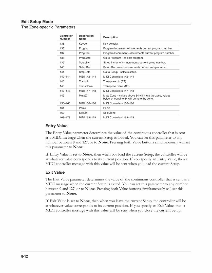
Edit Setup ModeTheZone-specificParameters
8-12
Controller Number
Destination Name Description
135 KeyVel KeyVelocity136 ProgInc ProgramIncrement—incrementscurrentprogramnumber.137 ProgDec ProgramDecrement—decrementscurrentprogramnumber.138 ProgGoto GotoProgram—selectsprogram.139 SetupInc SetupIncrement—incrementscurrentsetupnumber.140 SetupDec SetupDecrement—incrementscurrentsetupnumber.141 SetpGoto GotoSetup—selectssetup.142–144 MIDI142–144 MIDIControllers142–144145 TransUp TransposeUp(ST)146 TransDown TransposeDown(ST)147–148 MIDI147–148 MIDIControllers147–148149 MuteZn MuteZone–valuesabove64willmutethezone,values
beloworequalto64willunmutethezone.150–160 MIDI150–160 MIDIControllers150–160161 Panic Panic162 SoloZn SoloZone163–178 MIDI163–178 MIDIControllers163–178
Entry ValueThe Entry Value parameter determines the value of the continuous controller that is sent as a MIDI message when the current Setup is loaded. You can set this parameter to any number between 0 and 127, or to None. Pressing both Value buttons simultaneously will set this parameter to None.
If Entry Value is set to None, then when you load the current Setup, the controller will be at whatever value corresponds to its current position. If you specify an Entry Value, then a MIDI controller message with this value will be sent when you load the current Setup.
Exit ValueThe Exit Value parameter determines the value of the continuous controller that is sent as a MIDI message when the current Setup is exited. You can set this parameter to any number between 0 and 127, or to None. Pressing both Value buttons simultaneously will set this parameter to None.
If Exit Value is set to None, then when you leave the current Setup, the controller will be at whatever value corresponds to its current position. If you specify an Exit Value, then a MIDI controller message with this value will be sent when you close the current Setup.
Edit Setup ModeTheZone-specificParameters
8-13
The Foot Switch ParametersThere are four parameters that affect the behavior of the Foot Switch controller:
DestinationThe Destination parameter determines the MIDI destination for the currently selected controller in the currently selected Zone. For a list of the MIDI destinations and their descriptions, see Destination on page 8-10.
ModeThe Mode parameter determines the switching action of the Foot Switch. You can set this parameter either of two settings:
Momentary A momentary switch is one that is only in the “on” state when it is pressed. As soon as you release the switch, it goes into the “off ” state.
Toggled A toggled switch is one that maintains its state after it is pressed. So, if the switch is currently in the “off ” state, pressing it once will put it in the “on” state. Pressing it again will put it back in the “off ” state.
Pressing both Value buttons simultaneously will set this parameter to Toggled.
Entry StateThe Entry State parameter determines the state of the Foot Switch that is sent as a MIDI message when the current Setup is loaded. You can set this parameter to None, On, or Off. Pressing both Value buttons simultaneously will set this parameter to None.
If Entry State is set to None, then when you load the current Setup, the Foot Switch will be at whatever value corresponds to its current position. If you specify an Entry State, then a MIDI controller message with this value will be sent when you load the current Setup.
Exit StateThe Exit State parameter determines the state of the Foot Switch that is sent as a MIDI message when the current Setup is exited. You can set this parameter to None, On, or Off. Pressing both Value buttons simultaneously will set this parameter to None.
If Exit State is set to None, then when you close the current Setup, the Foot Switch will be at whatever value corresponds to its current position. If you specify an Exit State, then a MIDI controller message with this value will be sent when you close the current Setup.
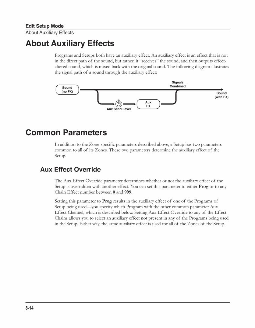
Edit Setup ModeAboutAuxiliaryEffects
8-14
About Auxiliary EffectsPrograms and Setups both have an auxiliary effect. An auxiliary effect is an effect that is not in the direct path of the sound, but rather, it “receives” the sound, and then outputs effect-altered sound, which is mixed back with the original sound. The following diagram illustrates the signal path of a sound through the auxiliary effect:
Common ParametersIn addition to the Zone-specific parameters described above, a Setup has two parameters common to all of its Zones. These two parameters determine the auxiliary effect of the Setup.
Aux Effect OverrideThe Aux Effect Override parameter determines whether or not the auxiliary effect of the Setup is overridden with another effect. You can set this parameter to either Prog or to any Chain Effect number between 0 and 999.
Setting this parameter to Prog results in the auxiliary effect of one of the Programs of Setup being used—you specify which Program with the other common parameter Aux Effect Channel, which is described below. Setting Aux Effect Override to any of the Effect Chains allows you to select an auxiliary effect not present in any of the Programs being used in the Setup. Either way, the same auxiliary effect is used for all of the Zones of the Setup.
Sound(no FX)
Aux Send Level
SignalsCombined
AuxFX
Sound(with FX)
Edit Setup ModeSavinginSetupMode
8-15
Aux Effect ChannelWith Prog selected for the Aux Effect Override parameter, the Aux Effect Channel parameter allows you to choose which Zone’s auxiliary effect is used for the entire Setup. You can set this parameter to any of MIDI channels of the Zones currently in use within the Setup.
Selecting the channel of one of the active Zones within the Setup will load the auxiliary effect of that Zone’s Program as the auxiliary effect of the Setup. Note that changing this parameter only results in a change in sound if Prog is selected for Aux Effect Override. If an Effect Chain is specified for Aux Effect Override, then that effect—not the effect on the channel specified for Aux Effect Channel—will be in use.
Saving in Setup Mode
When you make a change to the current Setup using the Control Knob, the Save button LED will light up indicating that a change has been made to the Setup. To save the current Setup, press the Save button once. The Save button LED will blink to indicate that a save operation is underway, and the User Bank LED will also be lit. If the Setup is an edited Factory Setup (i.e., a Setup in Bank 1), the default save location will be the next available location in the User Bank. If all 64 User Bank slots are taken, then the Setup is saved in the last slot in the User Bank, overwriting what was previously in that slot. If the current Setup is a Setup already in the User Bank, then the Setup is saved in its current Setup slot. At this point, you can rename the new Setup using the secondary alphanumeric functions of the Group Select and Sound Select buttons.
When the Save button LED is blinking (which means that you pressed Save, and a save operation is underway), pressing Save again will cause the system to save the current Setup to the indicated Group and Sound in the User Bank. If you want to save it to a different location in the User Bank, select the location via the Group Select and Sound Select buttons (or using the Value buttons) before pressing Save again.
Pressing any other button while the Save button is blinking will cancel the save operation.

Edit Setup ModeSavinginSetupMode
8-16
Global Mode
9-1
Chapter 9Global Mode
This chapter will help you familiarize yourself with the features of Global mode.
Global Mode gives you access to the global parameters of the SP4—that is, it allows you to edit the master settings of the unit. It also allows you to restore factory defaults on the unit by performing a Hard Reset.
CAUTION: PERFORMING A HARD RESET WILL DELETE ALL USER-CREATED PROGRAMS, SETUPS, AND GLOBAL SETTINGS.
To enter Global mode from another mode, press the Global Function button. While you are in Global mode, the Global button’s indicator LED is illuminated. When you enter Global mode, the last selected parameter since power-up (or the Tuning parameter if you’re entering Global mode for the first time since power-up) will be the currently selected parameter.
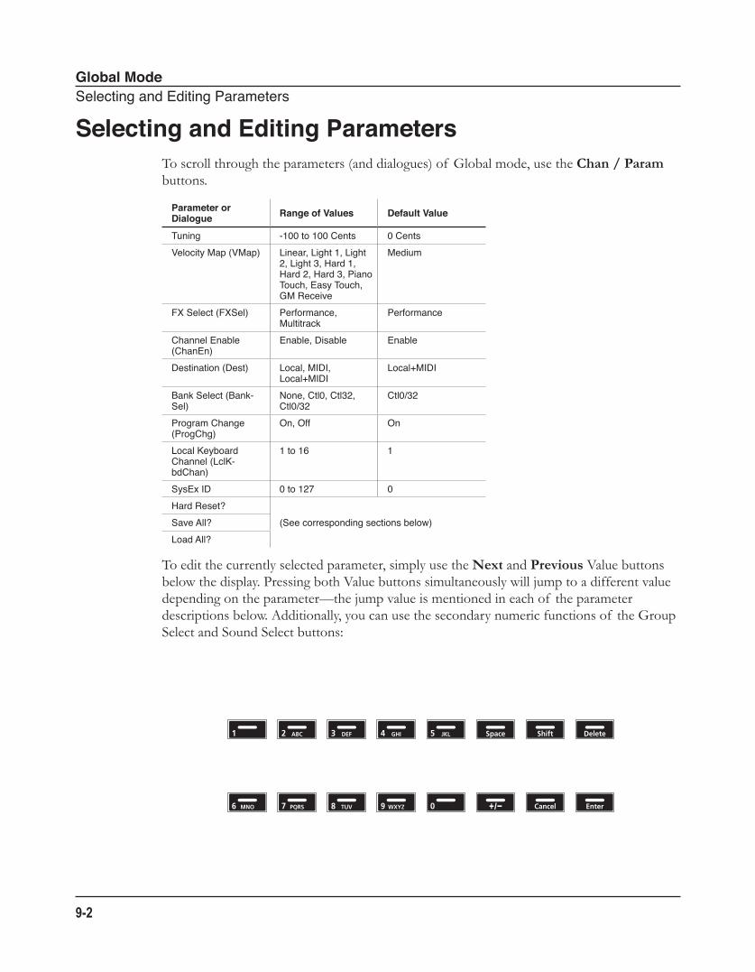
Global ModeSelectingandEditingParameters
9-2
Selecting and Editing ParametersTo scroll through the parameters (and dialogues) of Global mode, use the Chan / Param buttons.
Parameter or Dialogue Range of Values Default Value
Tuning -100to100Cents 0CentsVelocityMap(VMap) Linear,Light1,Light
2,Light3,Hard1,Hard2,Hard3,PianoTouch,EasyTouch,GMReceive
Medium
FXSelect(FXSel) Performance,Multitrack
Performance
ChannelEnable(ChanEn)
Enable,Disable Enable
Destination(Dest) Local,MIDI,Local+MIDI
Local+MIDI
BankSelect(Bank-Sel)
None,Ctl0,Ctl32,Ctl0/32
Ctl0/32
ProgramChange(ProgChg)
On,Off On
LocalKeyboardChannel(LclK-bdChan)
1to16 1
SysExID 0to127 0HardReset?
(Seecorrespondingsectionsbelow)SaveAll?LoadAll?
To edit the currently selected parameter, simply use the Next and Previous Value buttons below the display. Pressing both Value buttons simultaneously will jump to a different value depending on the parameter—the jump value is mentioned in each of the parameter descriptions below. Additionally, you can use the secondary numeric functions of the Group Select and Sound Select buttons:
Global ModeTheGlobalParameters
9-3
The Global ParametersThe following are the global parameters of the SP4. The settings of these parameters are in effect regardless of what Program or Setup you have currently selected.
TuningThe Tuning parameter allows you to fine-tune the unit in cents—one cent is one hundredth of a semitone (100 cents comprise a semitone). You can select any tuning from -100 cents to 100 cents. By default this parameter is set to 0. Pressing both Value buttons simultaneously will set this parameter to 0.
Velocity Map (VMap)The Velocity Map (VMap) parameter determines the way the SP4 generates MIDI velocity information. Different maps generate different MIDI velocity values for the same physical key strike velocity (note that this setting is applied to notes on top of any velocity settings made per Setup, per Zone). The default map (Linear) provides the widest range of velocity expression, but you may want to choose different map if the default does not suit your playing style You can select from any of the following settings:
Linear The MIDI output velocity is directly proportional to the strike velocity. The highest possible MIDI velocity will be output from the fastest velocity that the physical keys can detect, and the lowest possible MIDI velocity will be output from the slowest velocity that the physical keys can detect. All other MIDI and strike velocities are evenly spaced between these two extremes in the Linear map, allowing for an even distribution of strike and MIDI velocities.
Light 1 Light 2 Light 3
The MIDI output velocity is higher than with the Linear Velocity Map. From Light 1 to Light 3, it is easier to produce high MIDI velocity values for the same key strike velocity (with Light 3 being the easiest). These maps are best suited for ensemble playing.
Hard 1 Hard 2 Hard 3
The MIDI output velocity is lower than with the Linear Velocity Map. From Hard 1 to Hard 3, it is harder to produce high MIDI velocity values for the same key strike velocity (with Hard 3 being the hardest).
Global ModeTheGlobalParameters
9-4
Piano Touch The MIDI output velocity is similar to the strike velocity response of an acoustic piano, and is best suited for playing acoustic piano programs.
Easy Touch This Velocity Map is similar to the Light Maps and make high MIDI velocities easier to produce. But, it allows more sensitive control over producing high MIDI velocities by not boosting the MIDI velocity for fast strike velocities as much as it does for medium strike velocities.
GM Receive This Velocity Map mimics the Velocity Map commonly used by keyboards that use the General MIDI (GM) sound set. The GM Receive Map makes medium strike velocities produce higher MIDI velocities compared to the Linear map. GM Receive affects notes from the SP4’s keyboard as well as those from the MIDI in port.
Pressing both Value buttons simultaneously will set this parameter to Linear.
FX Select (FXSel)The FX Select (FXSel) parameter determines how the SP4 responds to interrupts with regards to effects. You can set this parameter to either Performance or Multitrack. Pressing both Value buttons simultaneously will set this parameter to Performance.
With FX Select set to Performance, the SP4 minimizes disruption of existing effects when changing Programs, and entry values will not disrupt sustained notes when changing Programs in Program Mode. When controlling the SP4 from an external sequencer in Program Mode, setting FX Select to Multitrack will minimize effect disruption.
Channel Enable (ChanEn)For each of the 16 MIDI channels, you can set the Channel Enable (ChanEn) parameter to either Enable or Disable. For each channel, setting this parameter to Enable enables the channel to transmit and receive MIDI messages and setting it to Disable disables such functions. Pressing both Value buttons simultaneously will set this parameter to Enable.
Destination (Dest)The Destination parameter determines the destination of MIDI data generated by striking keys or activating controllers. This data can be sent to the SP4 sound engine, through the MIDI out ports, or both. You can set this parameter to any of the three destinations for this parameter:
Global ModeTheGlobalParameters
9-5
Local MIDI data is sent only to the SP4 sound engine. The MIDI OUT port is disabled.
MIDI MIDI data is sent only through the MIDI OUT port. The sounds of the SP4 are disabled.
Local+MIDI MIDI data is sent both to the SP4 sound engine and through the MIDI OUT port.
Select the desired destination depending on your needs. If you want to play the SP4, but not send any MIDI information to other MIDI instruments, then select Local. If you want to use the SP4 strictly as a MIDI controller for the other modules in your MIDI chain, then select MIDI. If you want to make use of the SP4’s sounds as well as use it as a MIDI controller, then select Local+MIDI.
Pressing both Value buttons simultaneously will set this parameter to Local+MIDI.
Bank Select (BankSel)The Bank Mode parameter determines the controller number with which MIDI Bank change messages are transmitted. For MIDI Bank change messages, various manufacturers have chosen different MIDI controller numbers. Most have chosen 0, 32, or both.
You can set this parameter to any of the following four controller IDs:
None MIDI Bank change messages are disabled.
Ctl0 MIDI Bank change messages are sent with controller number 0.
Ctl32 MIDI Bank change messages are sent with controller number 32.
Ctl0/32 MIDI Bank change messages are sent with both controller numbers 0 and 32.
Pressing both Value buttons simultaneously will set this parameter to Ctl0/32.
Program Change (ProgChg)The Program Change (ProgChg) parameter determines whether or not entry MIDI Program Change messages are sent for Setups. You can set this parameter to either On or Off. Pressing both Value buttons simultaneously will set this parameter to On.
Note that when you perform a MIDI Program Change through MIDI Program Change Mode, the setting of the Global Program Change parameter (as well as the setting of the Global MIDI Transmit parameter) is ignored.
Global ModeTheGlobalParameters
9-6
Local Keyboard Channel (LclKbdChan)Changing the setting of the Local Keyboard Channel parameter is useful only when your SP4 is receiving MIDI information from an external source. Perhaps you have a favorite MIDI keyboard that you use to control all the gear in your studio, or you use a lot of outboard sequencing. If you’re using the SP4 as a standalone music workstation or performance keyboard, you can ignore this parameter.
The local keyboard channel enables the SP4 to receive MIDI information on a single channel, then rechannelize that information so you can play and control all four zones of a setup, even if your MIDI source transmits on only one channel. When you’re in Program mode, the local keyboard channel remaps incoming information to the SP4’s current channel. When using the local keyboard channel all the MIDI information received on the Local Keyboard Channel also gets sent—after being remapped—to the SP4’s MIDI and USB Out ports.
You may find it more convenient to use the local keyboard channel. In this case, the SP4 remaps incoming MIDI to the SP4’s current channel, so in Program mode, you’ll always play the program on the SP4’s current channel. Incoming MIDI also gets sent to the SP4’s MIDI and USB Out port. On the other hand, in this case your MIDI source’s transmitting channel must match the SP4’s local keyboard channel for anything to work.
Things are a bit different for playing Setups. In this case, you must use the Local Keyboard Channel to be able to play and control all of the Setup’s zones. Set LclKbdChan to match the channel your external MIDI source is using (if for example your MIDI source transmits on Channel 1, set LclKbdChan to 1). All MIDI information that the SP4 receives on the local keyboard channel gets remapped to the channels and control destinations used by the zones in the setup.
The SP4 also remaps certain MIDI Controller messages that it receives on the Local Keyboard Channel, so that they correspond (in most cases) to the default assignments for the SP4’s physical controllers (Mod Wheel, control knob, etc.). Physical controller assignments are handled by Setups, and are defined per Zone in Edit Setup Mode. Each Zone of a setup has its own controller assignments.
Sysex IDThe SysExID parameter determines the ID number for the unit if you are using more than one device with the same MIDI manufacturer ID number. You can set this parameter to any number from 0 to 127.
Unless you have multiple SP4s receiving Sysex messages from a single source, you will not need to change the Sysex ID from the default setting of 0.
Global ModeThe“HardReset?”Dialogue
9-7
If you do have multiple SP4s receiving Sysex messages from a single source, make sure each SP4 has a different Sysex ID. This will allow you to direct Sysex messages to the appropriate SP4 by specifying which unit with the Sysex ID byte that’s included with every Sysex message.
To have the unit respond to Sysex messages regardless of the Sysex ID, set Sysex ID to 127.
The “Hard Reset?” DialogueCAUTION: PERFORMING A HARD RESET WILL DELETE ALL USER-CREATED PROGRAMS AND SETUPS AND WILL RESTORE ALL PARAMETERS TO DEFAULT VALUES. THIS ACTION CANNOT BE UNDONE.
The “Hard Reset?” dialogue allows you to restore factory defaults to the SP4. Pressing Next in this dialogue will change the display to “Confirm?” Pressing Next in the “Confirm?” dialogue will result in a hard reset—pressing Previous in the “Confirm?” dialogue will recall the “Hard Reset?” dialogue.
Be sure to save your work off to external storage (See “The “Save All?” Dialogue” on page 9-7). Once deleted, the files are completely removed from the SP4 and there is no way to retrieve them.
To exit the Hard Reset dialogue, simply select another parameter using the Chan / Param buttons, or enter another Mode using the Mode Functions buttons.
The “Save All?” DialogueThe “Save All?” dialogue allows you to save every User-bank Program and User-bank Setup to a computer connected to the unit via USB. You can select Yes by pressing the Next Value button—pressing Previous will do nothing.
If a computer is connected and you select Yes, the display will show the message “Press Next for saving the file”. Pressing Previous will cancel the save operation and recall the “Save All?” dialogue. Pressing Next will save to the SP4 temporary drive and the display will show the message “The file is in the temporary drive, copy it to your hard disk”. If an error occurs during the save operation, then the display will show the error message “Save Error”.
If the SP4 is not connected to a computer, the display will show the error message “Please connect the unit to the computer”. Pressing Previous will recall the “Save All?” dialogue—pressing Next will retry to connect.
Global ModeThe“LoadAll?”Dialogue
9-8
The “Load All?” DialogueThe “Load All?” dialogue allows you to load a file containing previously saved User-bank Program and User-bank Setup from a computer connected to the unit via USB. You can select Yes by pressing the Next Value button—pressing Previous will do nothing.
If a computer is connected and you select Yes, the SP4 will appear on the connected computer as a temporary drive and the display will show “Put the file to be loaded into the temporary drive”. Pressing Previous will cancel the load operation and recall the “Load All?” dialogue. Pressing Next will load the file and the display will show “File loaded”. If no file is in the SP4 temporary drive during the load, the display will show the message “Nothing loaded”. If an error occurs during the load operation, then the display will show the error message “Load Error”.
If the SP4 is not connected to a computer, the display will show the error message “Please connect the unit to the computer”. Pressing Previous will recall the “Load All?” dialogue—pressing Next will retry to connect.
System Mode
10-1
Chapter 10System Mode
CAUTION: DO NOT ATTEMPT TO MAKE ANY CHANGES IN SYSTEM MODE UNTIL YOU HAVE READ AND FULLY UNDERSTOOD THIS ENTIRE CHAPTER.
This chapter will help you familiarize yourself with the functions of System Mode.
System Mode allows you manage and upgrade the OS software of your SP4 as well as perform diagnostic tests of the instrument’s various internal systems and processes. Note that the functions that you have access to in System Mode govern the operation of your SP4, so only use System Mode when you must perform essential maintenance tasks.
To enter System Mode, follow these steps:
1. Power off your SP4.
2. Press and the hold the Shift button, and power on the unit. The display will show the text “Loading...” as if you were normally starting up the unit. Make sure to keep holding the Shift button until the text “SP4 bootloader vx.x” (where x.x is the version of the bootloader software) scrolls across the display. After this splash screen, you will be offered with the option “Run SP4_SP76II”.
3. Release the Shift button—at this point, you are in System Mode.
Using the Chan / Param buttons, you can scroll through the list of actions of System Mode:
• Run SP4
• Update Software
• Run Diagnostics
• System Reset
• File Utilities
CAUTION: THE System Reset AND File Utilities OPERATIONS BOTH ERASE ALL USER OBJECTS.
System ModeButtonsinSystemMode
10-2
Buttons in System ModeThe following buttons have the following functionalities in System Mode:
Previous Move to parent menu. Similar to a “cancel” button.
Next Make selection and move into sub-menu if any. Like an “OK” button.
Chan / Param Up Move to “previous” menu option within a menu/sub-menu or scroll up to read diagnostic or other results/messages, when diagnostics are complete.
Chan / Param Down Move to “next” menu option, when in a menu or scroll down to read diagnostic or other results/messages, when diagnostics are complete.
Run SP4This is first option that System Mode offers. Pressing Next will load the OS and the SP4 will start up as if you just switched on the unit (except for the “Loading...” message that happens when you first start up the unit).
Update SoftwareThis group of operations is used to install OS and Object updates from Kurzweil. The Update files have an extension “KUF”, which is a compressed archive of all software updates required for the system.
Update1. Obtain the Update file from the Kurzweil website or another reliable source, save it in a
known folder or directory your computer.
2. Connect the SP4 (powered off) to your computer with a USB cord. Then enter System Mode as specified on page 10-1. The SP4 will appear as drive on your computer.
3. Press Chan / Param Down once. This will take you to the next option which is “Update Software”. Press Next to select this group of operations. This will give you with the option “Update”.
4. Press Next to start the Update operation. The displayed message will ask you to copy the Update file to the SP4 drive on your computer. Copy the file. Once copied, “Safely Remove” or “Unmount” the removable disk/drive from your computer.
System ModeRunDiagnostics
10-3
5. Press Next on your SP4. If the KUF file is valid, then the SP4 will display the message “Updating”. This will take a minute or two.
6. Once you see a “Done” message, power cycle unit or press Previous to go back to System Mode main menu.
RestoreWhenever you update the SP4’s software, a backup of the currently installed software is made. This is in case of a need to revert back to the old software, such as if the new update has problems or for simply for troubleshooting.
NOTE: Only the previously installed version of the software is backed up. When you perform a Restore operation again, the current version is backed up. So, it’s possible to go back and forth between versions.
Unlike the Update operation, the Restore operation can be performed without a computer connected to the SP4:
1. Start off by entering System Mode as specified on page 10-1.
2. Press Chan / Param Down once. This will take you to the next option which is “Update Software”. Press Next to select this group of operations. This will give you with the option “Update”.
3. Press Chan / Param Down once. This will take you to the next option which is “Restore”.
4. Press Next to perform the Restore operation.
Run DiagnosticsYou will most likely not need to use the Run Diagnostics operations in normal cases. These operations are mostly used at the factory and service centers by engineers for troubleshooting problems with hardware. But, in some cases you might be required to run these diagnostics for troubleshooting and diagnosing symptoms. In these cases, following the direction of an authorized Kurzweil technician.
System ResetCAUTION: THIS OPERATION ERASES ALL USER OBJECTS.
If you’ve made many, complex updates to your Objects, and have saved a number of files off to external storage, you might want to restore the instrument to its default state. This is especially helpful if you’re having problems getting sound programs or setups to work properly, or think there may be some kind of underlying hardware problem.
System ModeFileUtilities
10-4
To clear all user objects and restore the factory default state, select the System Reset utility using the Chan / Param buttons, and then press the Next Value button. The SP4 will ask you to confirm this action. Press the Next Value button to complete the system reset, or press the Previous Value button to stop the operation.
Remember to save your work off to external storage using Global Mode (See The “Save All?” Dialogue on page 9-7). Once deleted, the files are completely removed from the SP4 and there is no way to retrieve them.
File UtilitiesCAUTION: THIS OPERATION ERASES THE OPERATING SYSTEM, ALL FACTORY OBJECTS AND ALL USER OBJECTS.
File Utilities has only one operation: Format. Performing this operation will format the SP4’s system flash memory and erase the OS software as well as all Objects. Do not do this unless you think it is necessary in order to improve the performance of your SP4. Should you decide to do so, be sure to back up all of your files and software. After you do this, System Mode will still be available, so you can run updates and get your SP4 up-and-running again. After a Format the unit will come up in System Mode by default.
To perform a Format, follow these steps:
1. Start off by entering System Mode as specified on page 10-1.
2. Press Chan / Param Up once. This will take you to the previous option which is “File Utilities”. Press Next to select this operation. The unit display the message “Delete All?”.
3. Press Next to perform the Format operation.
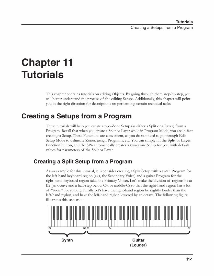
TutorialsCreatingaSetupsfromaProgram
11-1
Chapter 11Tutorials
This chapter contains tutorials on editing Objects. By going through them step-by-step, you will better understand the process of the editing Setups. Additionally, this chapter will point you in the right direction for descriptions on performing certain technical tasks.
Creating a Setups from a ProgramThese tutorials will help you create a two-Zone Setup (as either a Split or a Layer) from a Program. Recall that when you create a Split or Layer while in Program Mode, you are in fact creating a Setup. These Functions are convenient, as you do not need to go through Edit Setup Mode to delineate Zones, assign Programs, etc. You can simply hit the Split or Layer Function button, and the SP4 automatically creates a two-Zone Setup for you, with default values for parameters of the Split or Layer.
Creating a Split Setup from a ProgramAs an example for this tutorial, let’s consider creating a Split Setup with a synth Program for the left-hand keyboard region (aka, the Secondary Voice) and a guitar Program for the right-hand keyboard region (aka, the Primary Voice). Let’s make the division of regions be at B2 (an octave and a half-step below C4, or middle-C) so that the right-hand region has a lot of “room” for soloing. Finally, let’s have the right-hand region be slightly louder than the left-hand region, and have the left-hand region lowered by an octave. The following figure illustrates this scenario:
Synth Guitar(Louder)
C4C3B2E1 G7
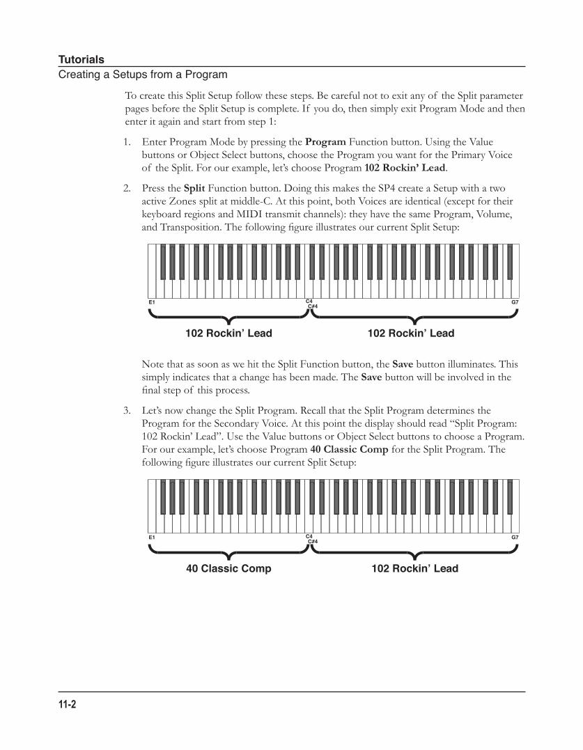
TutorialsCreatingaSetupsfromaProgram
11-2
To create this Split Setup follow these steps. Be careful not to exit any of the Split parameter pages before the Split Setup is complete. If you do, then simply exit Program Mode and then enter it again and start from step 1:
1. Enter Program Mode by pressing the Program Function button. Using the Value buttons or Object Select buttons, choose the Program you want for the Primary Voice of the Split. For our example, let’s choose Program 102 Rockin’ Lead.
2. Press the Split Function button. Doing this makes the SP4 create a Setup with a two active Zones split at middle-C. At this point, both Voices are identical (except for their keyboard regions and MIDI transmit channels): they have the same Program, Volume, and Transposition. The following figure illustrates our current Split Setup:
Note that as soon as we hit the Split Function button, the Save button illuminates. This simply indicates that a change has been made. The Save button will be involved in the final step of this process.
3. Let’s now change the Split Program. Recall that the Split Program determines the Program for the Secondary Voice. At this point the display should read “Split Program: 102 Rockin’ Lead”. Use the Value buttons or Object Select buttons to choose a Program. For our example, let’s choose Program 40 Classic Comp for the Split Program. The following figure illustrates our current Split Setup:
102 Rockin’ Lead 102 Rockin’ Lead
C4C#4
E1 G7
40 Classic Comp 102 Rockin’ Lead
C4C#4
E1 G7
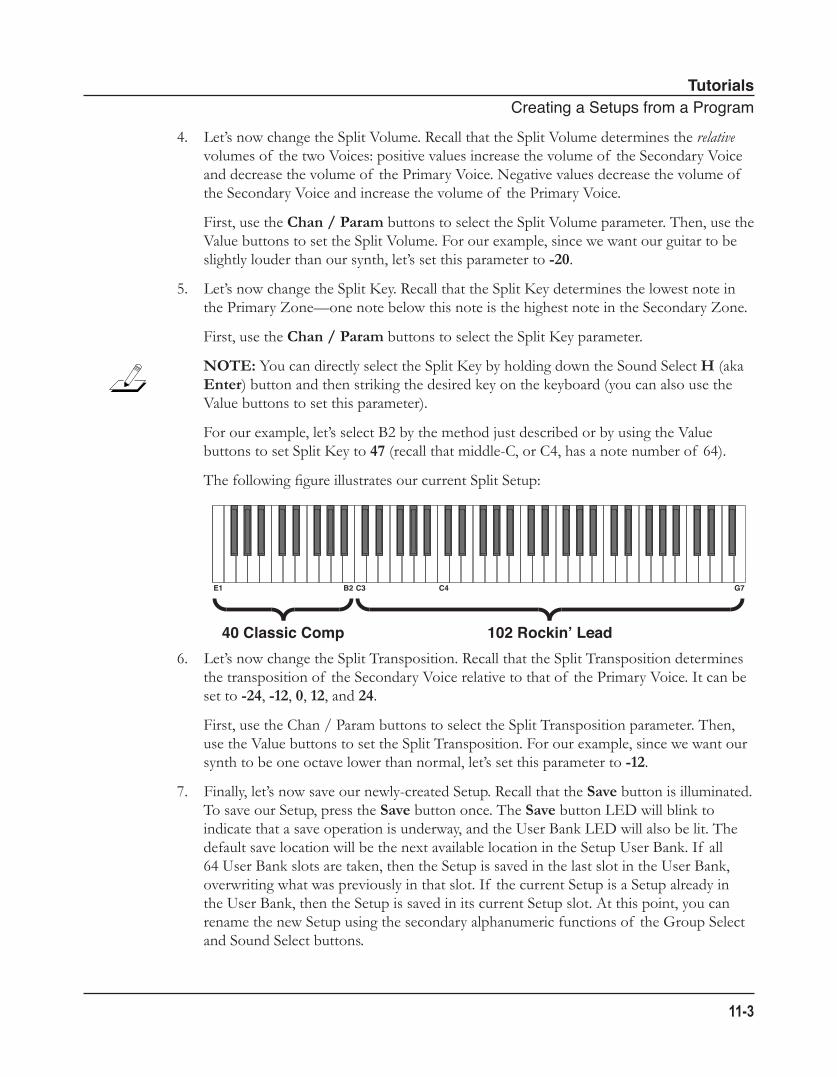
TutorialsCreatingaSetupsfromaProgram
11-3
4. Let’s now change the Split Volume. Recall that the Split Volume determines the relative volumes of the two Voices: positive values increase the volume of the Secondary Voice and decrease the volume of the Primary Voice. Negative values decrease the volume of the Secondary Voice and increase the volume of the Primary Voice. First, use the Chan / Param buttons to select the Split Volume parameter. Then, use the Value buttons to set the Split Volume. For our example, since we want our guitar to be slightly louder than our synth, let’s set this parameter to -20.
5. Let’s now change the Split Key. Recall that the Split Key determines the lowest note in the Primary Zone—one note below this note is the highest note in the Secondary Zone. First, use the Chan / Param buttons to select the Split Key parameter. NOTE: You can directly select the Split Key by holding down the Sound Select H (aka Enter) button and then striking the desired key on the keyboard (you can also use the Value buttons to set this parameter). For our example, let’s select B2 by the method just described or by using the Value buttons to set Split Key to 47 (recall that middle-C, or C4, has a note number of 64). The following figure illustrates our current Split Setup:
6. Let’s now change the Split Transposition. Recall that the Split Transposition determines the transposition of the Secondary Voice relative to that of the Primary Voice. It can be set to -24, -12, 0, 12, and 24. First, use the Chan / Param buttons to select the Split Transposition parameter. Then, use the Value buttons to set the Split Transposition. For our example, since we want our synth to be one octave lower than normal, let’s set this parameter to -12.
7. Finally, let’s now save our newly-created Setup. Recall that the Save button is illuminated. To save our Setup, press the Save button once. The Save button LED will blink to indicate that a save operation is underway, and the User Bank LED will also be lit. The default save location will be the next available location in the Setup User Bank. If all 64 User Bank slots are taken, then the Setup is saved in the last slot in the User Bank, overwriting what was previously in that slot. If the current Setup is a Setup already in the User Bank, then the Setup is saved in its current Setup slot. At this point, you can rename the new Setup using the secondary alphanumeric functions of the Group Select and Sound Select buttons.
40 Classic Comp 102 Rockin’ Lead
C4C3B2E1 G7
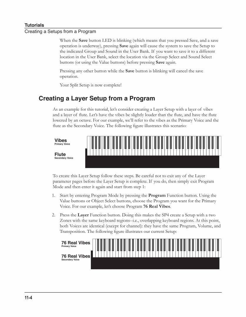
TutorialsCreatingaSetupsfromaProgram
11-4
When the Save button LED is blinking (which means that you pressed Save, and a save operation is underway), pressing Save again will cause the system to save the Setup to the indicated Group and Sound in the User Bank. If you want to save it to a different location in the User Bank, select the location via the Group Select and Sound Select buttons (or using the Value buttons) before pressing Save again. Pressing any other button while the Save button is blinking will cancel the save operation. Your Split Setup is now complete!
Creating a Layer Setup from a ProgramAs an example for this tutorial, let’s consider creating a Layer Setup with a layer of vibes and a layer of flute. Let’s have the vibes be slightly louder than the flute, and have the flute lowered by an octave. For our example, we’ll refer to the vibes as the Primary Voice and the flute as the Secondary Voice. The following figure illustrates this scenario:
To create this Layer Setup follow these steps. Be careful not to exit any of the Layer parameter pages before the Layer Setup is complete. If you do, then simply exit Program Mode and then enter it again and start from step 1:
1. Start by entering Program Mode by pressing the Program Function button. Using the Value buttons or Object Select buttons, choose the Program you want for the Primary Voice. For our example, let’s choose Program 76 Real Vibes.
2. Press the Layer Function button. Doing this makes the SP4 create a Setup with a two Zones with the same keyboard regions--i.e., overlapping keyboard regions. At this point, both Voices are identical (except for channel): they have the same Program, Volume, and Transposition. The following figure illustrates our current Setup:
VibesPrimary Voice
FluteSecondary Voice
76 Real VibesPrimary Voice
76 Real VibesSecondary Voice
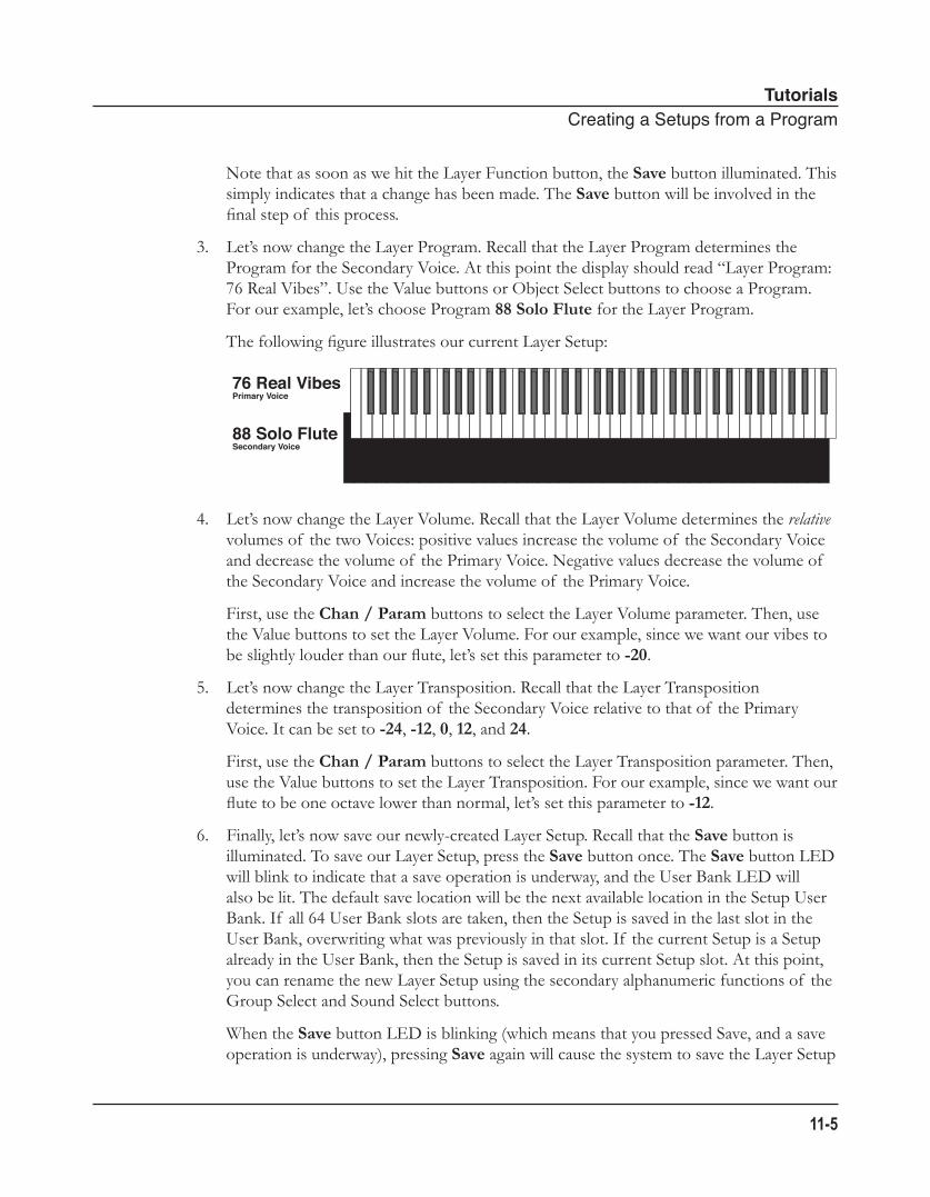
TutorialsCreatingaSetupsfromaProgram
11-5
Note that as soon as we hit the Layer Function button, the Save button illuminated. This simply indicates that a change has been made. The Save button will be involved in the final step of this process.
3. Let’s now change the Layer Program. Recall that the Layer Program determines the Program for the Secondary Voice. At this point the display should read “Layer Program: 76 Real Vibes”. Use the Value buttons or Object Select buttons to choose a Program. For our example, let’s choose Program 88 Solo Flute for the Layer Program. The following figure illustrates our current Layer Setup:
4. Let’s now change the Layer Volume. Recall that the Layer Volume determines the relative volumes of the two Voices: positive values increase the volume of the Secondary Voice and decrease the volume of the Primary Voice. Negative values decrease the volume of the Secondary Voice and increase the volume of the Primary Voice. First, use the Chan / Param buttons to select the Layer Volume parameter. Then, use the Value buttons to set the Layer Volume. For our example, since we want our vibes to be slightly louder than our flute, let’s set this parameter to -20.
5. Let’s now change the Layer Transposition. Recall that the Layer Transposition determines the transposition of the Secondary Voice relative to that of the Primary Voice. It can be set to -24, -12, 0, 12, and 24. First, use the Chan / Param buttons to select the Layer Transposition parameter. Then, use the Value buttons to set the Layer Transposition. For our example, since we want our flute to be one octave lower than normal, let’s set this parameter to -12.
6. Finally, let’s now save our newly-created Layer Setup. Recall that the Save button is illuminated. To save our Layer Setup, press the Save button once. The Save button LED will blink to indicate that a save operation is underway, and the User Bank LED will also be lit. The default save location will be the next available location in the Setup User Bank. If all 64 User Bank slots are taken, then the Setup is saved in the last slot in the User Bank, overwriting what was previously in that slot. If the current Setup is a Setup already in the User Bank, then the Setup is saved in its current Setup slot. At this point, you can rename the new Layer Setup using the secondary alphanumeric functions of the Group Select and Sound Select buttons. When the Save button LED is blinking (which means that you pressed Save, and a save operation is underway), pressing Save again will cause the system to save the Layer Setup
76 Real VibesPrimary Voice
88 Solo FluteSecondary Voice
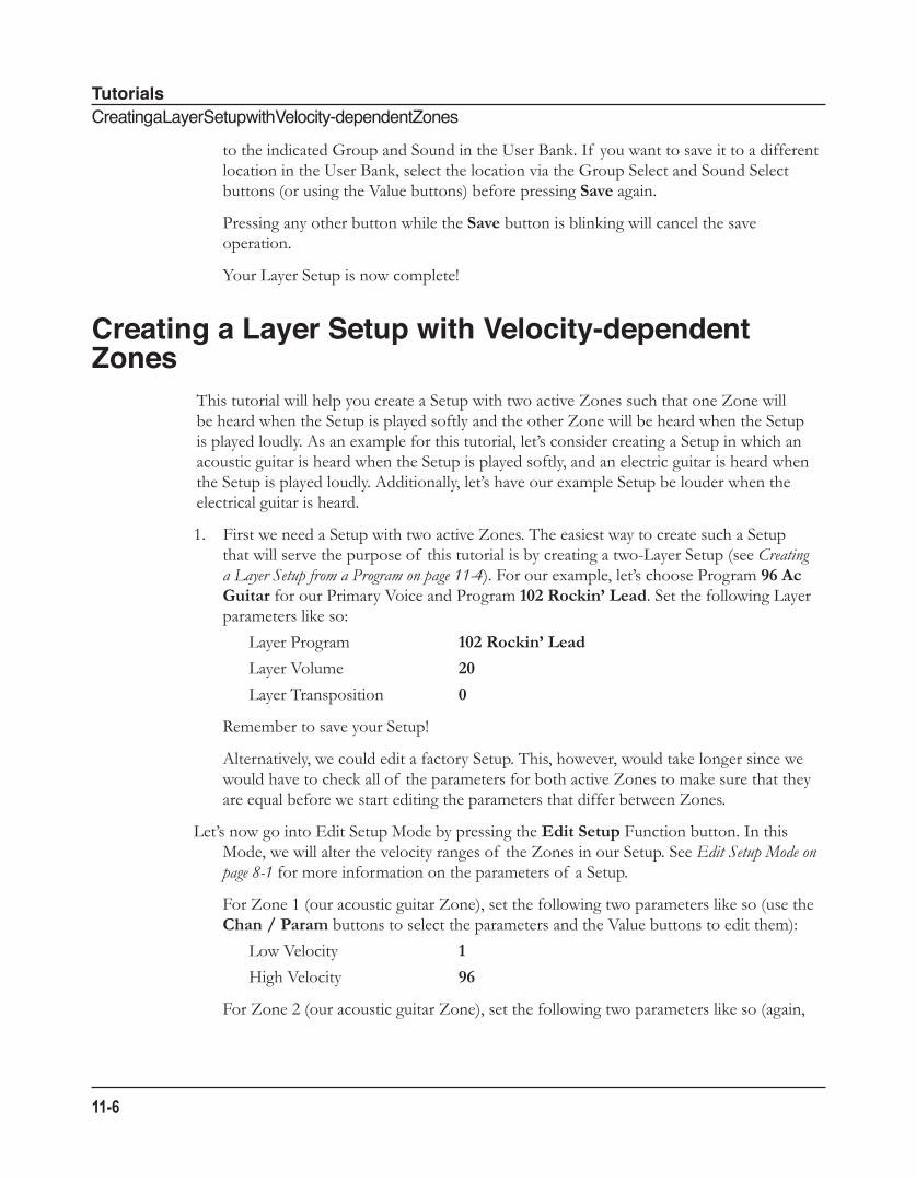
TutorialsCreatingaLayerSetupwithVelocity-dependentZones
11-6
to the indicated Group and Sound in the User Bank. If you want to save it to a different location in the User Bank, select the location via the Group Select and Sound Select buttons (or using the Value buttons) before pressing Save again. Pressing any other button while the Save button is blinking will cancel the save operation. Your Layer Setup is now complete!
Creating a Layer Setup with Velocity-dependent Zones
This tutorial will help you create a Setup with two active Zones such that one Zone will be heard when the Setup is played softly and the other Zone will be heard when the Setup is played loudly. As an example for this tutorial, let’s consider creating a Setup in which an acoustic guitar is heard when the Setup is played softly, and an electric guitar is heard when the Setup is played loudly. Additionally, let’s have our example Setup be louder when the electrical guitar is heard.
1. First we need a Setup with two active Zones. The easiest way to create such a Setup that will serve the purpose of this tutorial is by creating a two-Layer Setup (see Creating a Layer Setup from a Program on page 11-4). For our example, let’s choose Program 96 Ac Guitar for our Primary Voice and Program 102 Rockin’ Lead. Set the following Layer parameters like so:
Layer Program 102 Rockin’ Lead
Layer Volume 20
Layer Transposition 0
Remember to save your Setup!
Alternatively, we could edit a factory Setup. This, however, would take longer since we would have to check all of the parameters for both active Zones to make sure that they are equal before we start editing the parameters that differ between Zones.
Let’s now go into Edit Setup Mode by pressing the Edit Setup Function button. In this Mode, we will alter the velocity ranges of the Zones in our Setup. See Edit Setup Mode on page 8-1 for more information on the parameters of a Setup. For Zone 1 (our acoustic guitar Zone), set the following two parameters like so (use the Chan / Param buttons to select the parameters and the Value buttons to edit them):
Low Velocity 1
High Velocity 96 For Zone 2 (our acoustic guitar Zone), set the following two parameters like so (again,
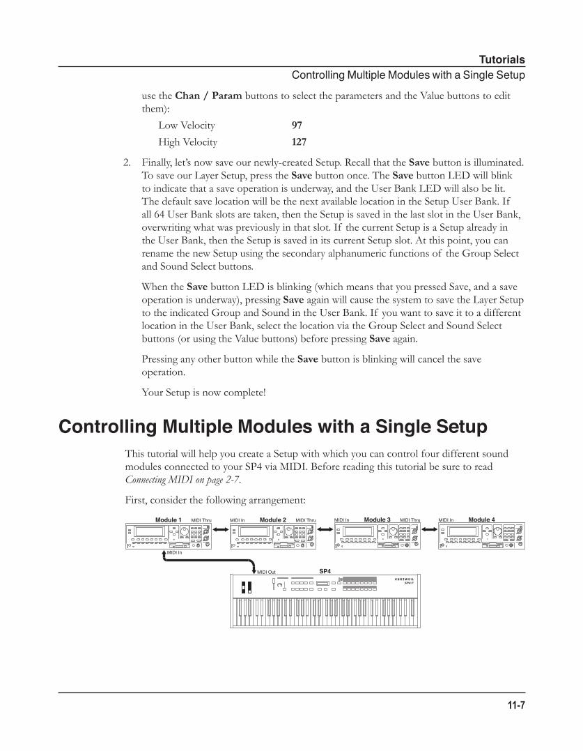
TutorialsControllingMultipleModuleswithaSingleSetup
11-7
use the Chan / Param buttons to select the parameters and the Value buttons to edit them):
Low Velocity 97
High Velocity 127
2. Finally, let’s now save our newly-created Setup. Recall that the Save button is illuminated. To save our Layer Setup, press the Save button once. The Save button LED will blink to indicate that a save operation is underway, and the User Bank LED will also be lit. The default save location will be the next available location in the Setup User Bank. If all 64 User Bank slots are taken, then the Setup is saved in the last slot in the User Bank, overwriting what was previously in that slot. If the current Setup is a Setup already in the User Bank, then the Setup is saved in its current Setup slot. At this point, you can rename the new Setup using the secondary alphanumeric functions of the Group Select and Sound Select buttons. When the Save button LED is blinking (which means that you pressed Save, and a save operation is underway), pressing Save again will cause the system to save the Layer Setup to the indicated Group and Sound in the User Bank. If you want to save it to a different location in the User Bank, select the location via the Group Select and Sound Select buttons (or using the Value buttons) before pressing Save again. Pressing any other button while the Save button is blinking will cancel the save operation. Your Setup is now complete!
Controlling Multiple Modules with a Single SetupThis tutorial will help you create a Setup with which you can control four different sound modules connected to your SP4 via MIDI. Before reading this tutorial be sure to read Connecting MIDI on page 2-7.
First, consider the following arrangement:
SP4
MIDI In
Module 1 MIDI Thru Module 2MIDI In MIDI Thru Module 3MIDI In MIDI Thru Module 4MIDI In
MIDI Out
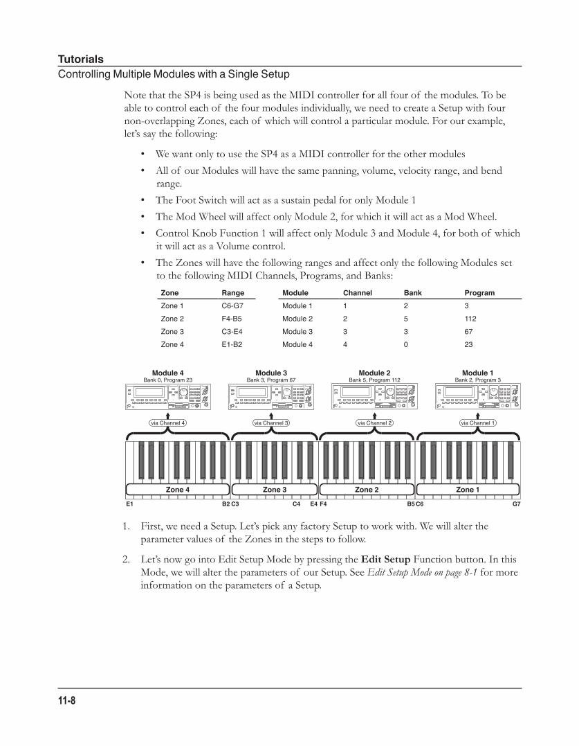
TutorialsControllingMultipleModuleswithaSingleSetup
11-8
Note that the SP4 is being used as the MIDI controller for all four of the modules. To be able to control each of the four modules individually, we need to create a Setup with four non-overlapping Zones, each of which will control a particular module. For our example, let’s say the following:
• We want only to use the SP4 as a MIDI controller for the other modules
• All of our Modules will have the same panning, volume, velocity range, and bend range.
• The Foot Switch will act as a sustain pedal for only Module 1
• The Mod Wheel will affect only Module 2, for which it will act as a Mod Wheel.
• Control Knob Function 1 will affect only Module 3 and Module 4, for both of which it will act as a Volume control.
• The Zones will have the following ranges and affect only the following Modules set to the following MIDI Channels, Programs, and Banks:
Zone Range Module Channel Bank ProgramZone1 C6-G7 Module1 1 2 3Zone2 F4-B5 Module2 2 5 112Zone3 C3-E4 Module3 3 3 67Zone4 E1-B2 Module4 4 0 23
1. First, we need a Setup. Let’s pick any factory Setup to work with. We will alter the parameter values of the Zones in the steps to follow.
2. Let’s now go into Edit Setup Mode by pressing the Edit Setup Function button. In this Mode, we will alter the parameters of our Setup. See Edit Setup Mode on page 8-1 for more information on the parameters of a Setup.
Module 4
C4C3 E4 F4 B5 C6 G7B2E1
Module 3 Module 2 Module 1Bank 0, Program 23 Bank 3, Program 67 Bank 5, Program 112 Bank 2, Program 3
via Channel 4 via Channel 3 via Channel 2 via Channel 1
Zone 4 Zone 3 Zone 2 Zone 1
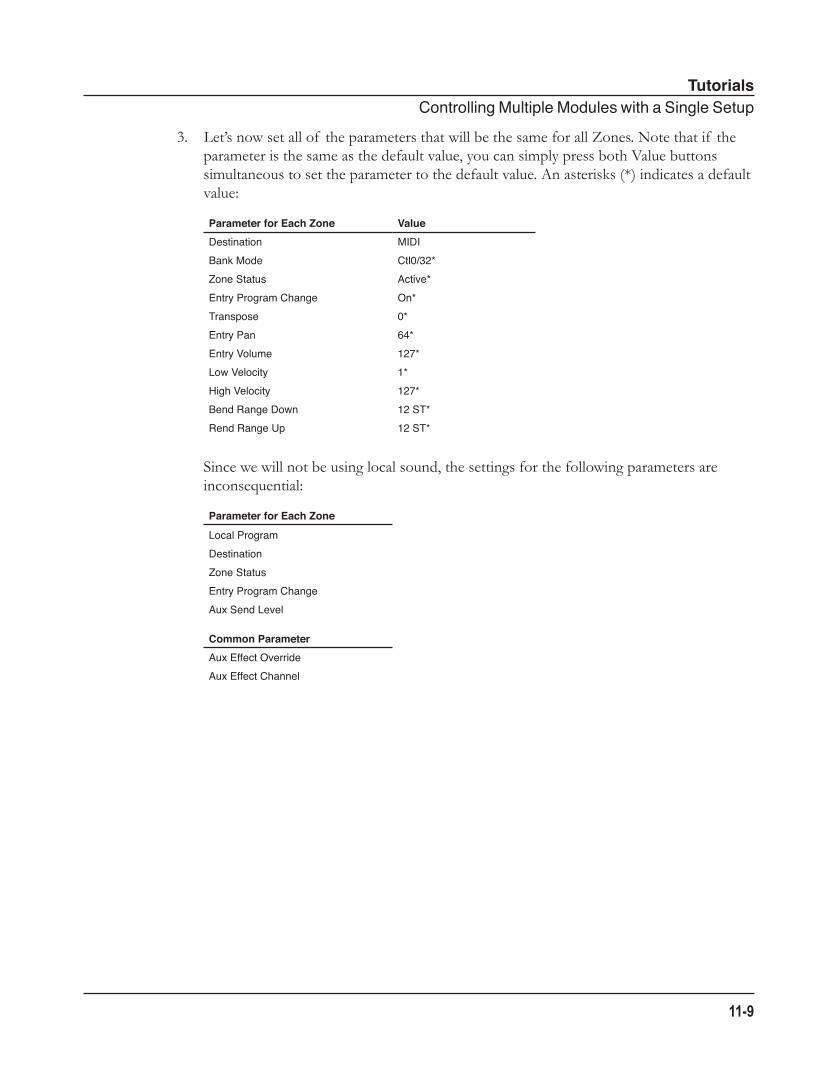
TutorialsControllingMultipleModuleswithaSingleSetup
11-9
3. Let’s now set all of the parameters that will be the same for all Zones. Note that if the parameter is the same as the default value, you can simply press both Value buttons simultaneous to set the parameter to the default value. An asterisks (*) indicates a default value: Parameter for Each Zone ValueDestination MIDIBankMode Ctl0/32*ZoneStatus Active*EntryProgramChange On*Transpose 0*EntryPan 64*EntryVolume 127*LowVelocity 1*HighVelocity 127*BendRangeDown 12ST*RendRangeUp 12ST*
Since we will not be using local sound, the settings for the following parameters are inconsequential: Parameter for Each Zone
LocalProgramDestinationZoneStatusEntryProgramChangeAuxSendLevel
Common ParameterAuxEffectOverrideAuxEffectChannel
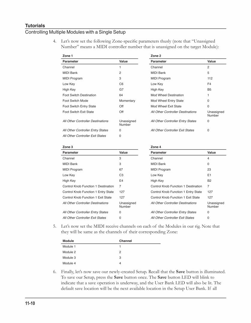
TutorialsControllingMultipleModuleswithaSingleSetup
11-10
4. Let’s now set the following Zone-specific parameters thusly (note that “Unassigned Number” means a MIDI controller number that is unassigned on the target Module): Zone 1 Zone 2Parameter Value Parameter Value
Channel 1 Channel 2MIDIBank 2 MIDIBank 5MIDIProgram 3 MIDIProgram 112LowKey C6 LowKey F4HighKey G7 HighKey B5FootSwitchDestination 64 ModWheelDestination 1FootSwitchMode Momentary ModWheelEntryState 0FootSwitchEntryState Off ModWheelExitState 0FootSwitchExitState Off All Other Controller Destinations Unassigned
NumberAll Other Controller Destinations Unassigned
NumberAll Other Controller Entry States 0
All Other Controller Entry States 0 All Other Controller Exit States 0All Other Controller Exit States 0
Zone 3 Zone 4Parameter Value Parameter Value
Channel 3 Channel 4MIDIBank 3 MIDIBank 0MIDIProgram 67 MIDIProgram 23LowKey C3 LowKey E1HighKey E4 HighKey B2ControlKnobFunction1Destination 7 ControlKnobFunction1Destination 7ControlKnobFunction1EntryState 127 ControlKnobFunction1EntryState 127ControlKnobFunction1ExitState 127 ControlKnobFunction1ExitState 127All Other Controller Destinations Unassigned
NumberAll Other Controller Destinations Unassigned
NumberAll Other Controller Entry States 0 All Other Controller Entry States 0All Other Controller Exit States 0 All Other Controller Exit States 0
5. Let’s now set the MIDI receive channels on each of the Modules in our rig. Note that they will be same as the channels of their corresponding Zone: Module ChannelModule1 1Module2 2Module3 3Module4 4
6. Finally, let’s now save our newly-created Setup. Recall that the Save button is illuminated. To save our Setup, press the Save button once. The Save button LED will blink to indicate that a save operation is underway, and the User Bank LED will also be lit. The default save location will be the next available location in the Setup User Bank. If all
TutorialsOtherTutorials
11-11
64 User Bank slots are taken, then the Setup is saved in the last slot in the User Bank, overwriting what was previously in that slot. If the current Setup is a Setup already in the User Bank, then the Setup is saved in its current Setup slot. At this point, you can rename the new Setup using the secondary alphanumeric functions of the Group Select and Sound Select buttons. When the Save button LED is blinking (which means that you pressed Save, and a save operation is underway), pressing Save again will cause the system to save the current Setup to the indicated Group and Sound in the User Bank. If you want to save it to a different location in the User Bank, select the location via the Group Select and Sound Select buttons (or using the Value buttons) before pressing Save again. Pressing any other button while the Save button is blinking will cancel the save operation. Your Setup is now complete!
Other Tutorials
Connecting to Your Sound SystemSee Connecting to Your Audio System on page 2-4.
Connecting MIDISee Connecting MIDI on page 2-7.
Managing Object DataSee The “Save All?” Dialogue on page 9-7 and The “Load All?” Dialogue on page 9-8.
Updating SoftwareSee Update Software on page 10-2.
TutorialsOtherTutorials
11-12
Restoring Factory DefaultsThere are two ways to restore factory defaults, both of which result in all user-created Objects being deleted. The first method is described in The “Hard Reset?” Dialogue on page 9-7. The second is described in System Reset on page 10-3.
CAUTION: RESTORING FACTORY DEFAULTS CANNOT BE UNDONE. BACK UP YOUR FILES BEFORE DOING SO BY FOLLOWING THE PROCEDURE IN The “Save All?” Dialogue on page 9-7.
TroubleshootingMaintenance
12-1
Chapter 12Troubleshooting
MaintenanceAside from normal care in handling and use, your SP4 requires no regular maintenance. Clean with a soft cloth dampened with water. Never use abrasives or solvents as they may damage the unit’s paint, markings, info strip and display lens. There are no batteries inside to replace—ever. Instead of volatile SRAM used in most other instruments, your SP4 uses nonvolatile EEPROM for storage, which retains information without power.
Common ProblemsBelow is a list of the most commonly encountered problems and diagnoses for each.
Power ProblemsThis is the normal power-up sequence:
1. The display backlight turns on.
2. “Loading...” appears on the display for a few seconds.
3. The unit enters Program mode with Grand Piano 0 selected.
If nothing at all happens when you turn the power switch on, check if one of the following might be the issue:
The power converter is not plugged securely into the wall outlet.
Plug the power converter securely into the wall outlet.
The cord from power converter is not plugged securely into the SP4 DC power jack.
Plug the power converter securely into the SP4 DC power jack.

TroubleshootingCommonProblems
12-2
The power converter ratings does not match the required ratings for the SP4. The power converter specifications are: 15V DC, 1.0 amp, center pin positive, 5.5mm OD, 2.5mm ID coax type plug.
Obtain a compatible power converter.
The wall outlet, power strip, or extension cord is defective or damaged.
Use a different wall outlet, power strip, or extension cord.
If there’s evidence of the unit receiving power, but operation is abnormal, check if one of the following might be the issue:
The power converter ratings does not match the required ratings for the SP4. The power converter specifications are: 15V DC, 1.0 amp, center pin positive, 5.5mm OD, 2.5mm ID coax type plug.
Obtain a compatible power converter.
The wall outlet voltage is below 90 volts due to overload.
Try a different outlet on a different circuit.
The power converter plug does not snugly fit into the DC power jack, causing it to wobble and provide intermittent power.
Obtain a compatible power convert.
TroubleshootingCommonProblems
12-3
Audio ProblemsCAUTION: DO NOT TROUBLE SHOOT AUDIO PROBLEMS USING HEADPHONES. ADDITIONALLY, ALWAYS BE AWARE OF THE VOLUME LEVELS ON THE SP4 AND ON THE CONNECTED AUDIO SYSTEM OR MIXER.
NOTE: When diagnosing audio problems, set the SP4 to play its demo sequence rather then intermittently pressing keys. This will prevent any unexpectedly loud volume changes.
If there is no sound from your SP4, check if one of the following might be the issue:
The volume slider is turned down.
Slowly push the volume slider up.
The volume control on the audio system or mixer is turned down.
Slowly turn the volume control up.
The signal source selection on the audio system or mixer is incorrect.
Set the volume of the audio or mixer to the lowest level, select the correct signal source, and then slowly turn up the volume.
The audio cables are not securely plugged into the SP4, audio system, or mixer.
Set the volume of the audio or mixer to the lowest level, securely plus in the audio cables on both ends, and then slowly turn up the volume.
The audio cable is of an incorrect type.
Obtain and securely connect an audio cable of the correct type. The SP4 accepts both balanced (TS) and unbalanced (TRS) 1/4-inch audio cables.
If you can hear sound but it is low or distorted, check if one of the following might be the issue:
The audio cables are not securely plugged into the SP4, audio system, or mixer.
Set the volume of the audio system or mixer to the lowest level, securely plus in the audio cables on both ends, and then slowly turn up the volume.
TroubleshootingCommonProblems
12-4
A received MIDI volume message has specified a low volume.
Set the volume of the audio system or mixer to the lowest level. Disconnect all MIDI cables, set the Destination parameter in Global Mode to Local or MIDI+Local, and reset the volume level on the SP4. Finally, slowly turn up the volume level of the audio system or mixer.
The current Setup has another controller assigned to volume, and it is turned down.
Select a different Setup. Or change the problematic controller setting by editing the Setup in Edit Setup Mode.
The input to the audio system is set for low impedance instead of high impedance.
Set the volume of the audio or mixer to the lowest level, change the impedance setting, and then slowly turn up the volume of the audio system or mixer.
The input trim to the audio system or mixer is set too low.
Slowly turn up the trim.
MIDI ProblemsIf you are experiencing problems sending MIDI to an external module, check if one of the following might be the issue:
The MIDI cable is not securely plugged in at both ends.
Securely plug in the MIDI cable at both ends.
The MIDI connections are wrong.
To send MIDI, plug the MIDI cable into the SP4’s MIDI Out port and into the module’s MIDI In port.
The MIDI cable is defective. Obtain and securely connect a new MIDI cable.
The MIDI transmit channel does not match that of the receiving device.
Change the channel on either the SP4 or on the device such that the channels match.
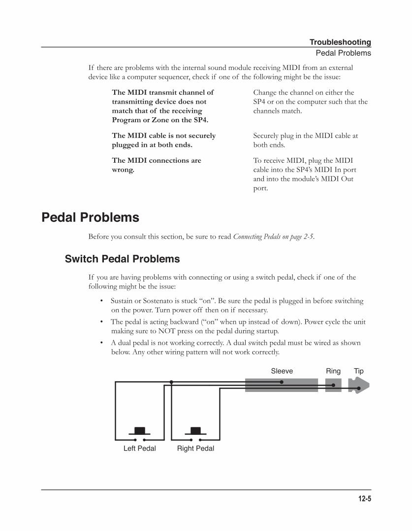
TroubleshootingPedalProblems
12-5
If there are problems with the internal sound module receiving MIDI from an external device like a computer sequencer, check if one of the following might be the issue:
The MIDI transmit channel of transmitting device does not match that of the receiving Program or Zone on the SP4.
Change the channel on either the SP4 or on the computer such that the channels match.
The MIDI cable is not securely plugged in at both ends.
Securely plug in the MIDI cable at both ends.
The MIDI connections are wrong.
To receive MIDI, plug the MIDI cable into the SP4’s MIDI In port and into the module’s MIDI Out port.
Pedal ProblemsBefore you consult this section, be sure to read Connecting Pedals on page 2-5.
Switch Pedal ProblemsIf you are having problems with connecting or using a switch pedal, check if one of the following might be the issue:
• Sustain or Sostenato is stuck “on”. Be sure the pedal is plugged in before switching on the power. Turn power off then on if necessary.
• The pedal is acting backward (“on” when up instead of down). Power cycle the unit making sure to NOT press on the pedal during startup.
• A dual pedal is not working correctly. A dual switch pedal must be wired as shown below. Any other wiring pattern will not work correctly.
Sleeve Ring Tip
Left Pedal Right Pedal
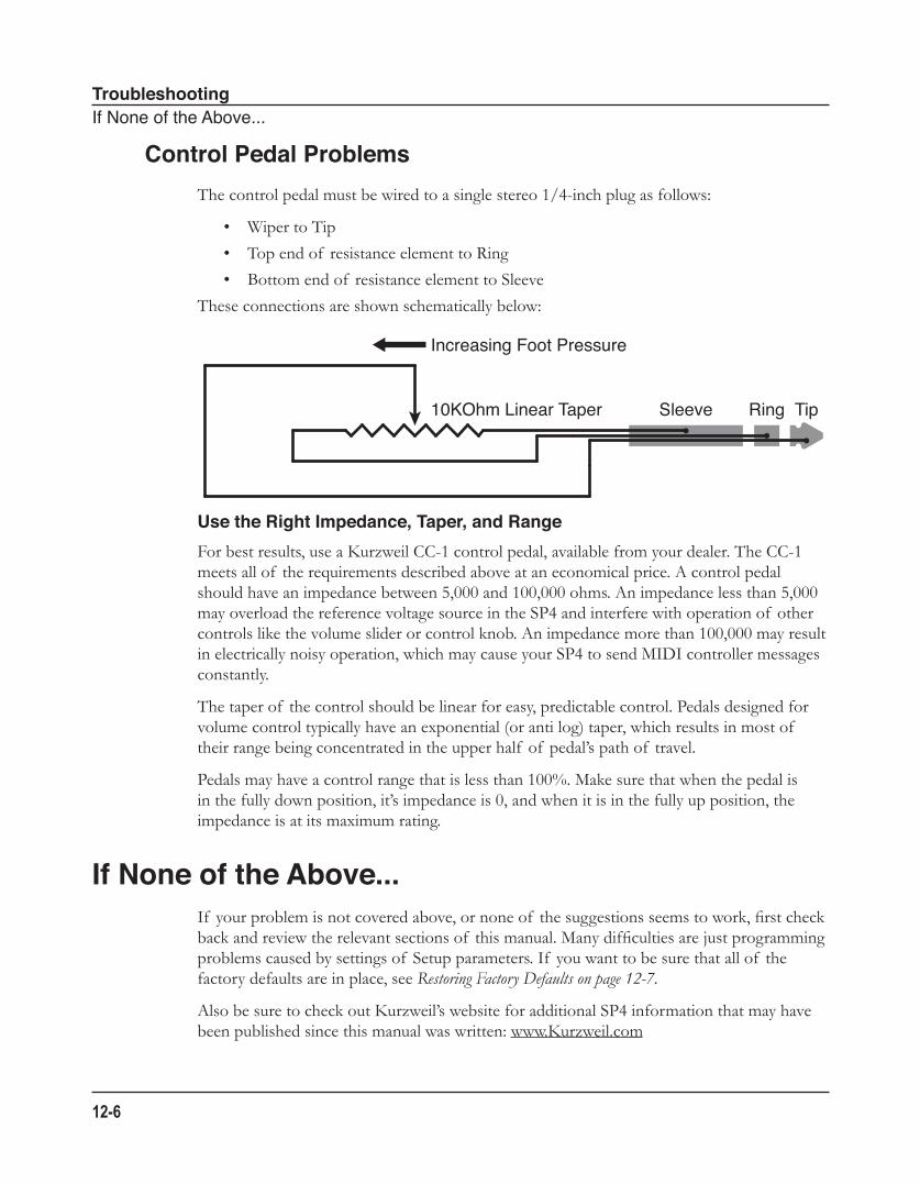
TroubleshootingIfNoneoftheAbove...
12-6
Control Pedal ProblemsThe control pedal must be wired to a single stereo 1/4-inch plug as follows:
• Wiper to Tip
• Top end of resistance element to Ring
• Bottom end of resistance element to Sleeve
These connections are shown schematically below:
Use the Right Impedance, Taper, and Range For best results, use a Kurzweil CC-1 control pedal, available from your dealer. The CC-1 meets all of the requirements described above at an economical price. A control pedal should have an impedance between 5,000 and 100,000 ohms. An impedance less than 5,000 may overload the reference voltage source in the SP4 and interfere with operation of other controls like the volume slider or control knob. An impedance more than 100,000 may result in electrically noisy operation, which may cause your SP4 to send MIDI controller messages constantly.
The taper of the control should be linear for easy, predictable control. Pedals designed for volume control typically have an exponential (or anti log) taper, which results in most of their range being concentrated in the upper half of pedal’s path of travel.
Pedals may have a control range that is less than 100%. Make sure that when the pedal is in the fully down position, it’s impedance is 0, and when it is in the fully up position, the impedance is at its maximum rating.
If None of the Above...If your problem is not covered above, or none of the suggestions seems to work, first check back and review the relevant sections of this manual. Many difficulties are just programming problems caused by settings of Setup parameters. If you want to be sure that all of the factory defaults are in place, see Restoring Factory Defaults on page 12-7.
Also be sure to check out Kurzweil’s website for additional SP4 information that may have been published since this manual was written: www.Kurzweil.com
Sleeve Ring Tip10KOhm Linear Taper
Increasing Foot Pressure
TroubleshootingIfNoneoftheAbove...
12-7
Service CentersContact the nearest Young Chang office Kurzweil service representative. See page iv in the front matter of this manual for contact info.
Restoring Factory DefaultsThere are two ways to restore factory defaults, both of which result in all user-created Objects being deleted. The first method is described in The “Hard Reset?” Dialogue on page 9-7. The second is described in System Reset on page 10-3.
CAUTION: RESTORING FACTORY DEFAULTS CANNOT BE UNDONE. BACK UP YOUR FILES BEFORE DOING SO BY FOLLOWING THE PROCEDURE IN The “Save All?” Dialogue on page 9-7.
DiagnosticsYou will most likely not need to use the System Mode diagnostic operations in normal cases. These operations are mostly used at the factory and service centers by engineers for troubleshooting problems with hardware. But, in some cases you might be required to run these diagnostics for troubleshooting and diagnosing symptoms. In these cases, follow the direction of an authorized Kurzweil technician.
TroubleshootingIfNoneoftheAbove...
12-8
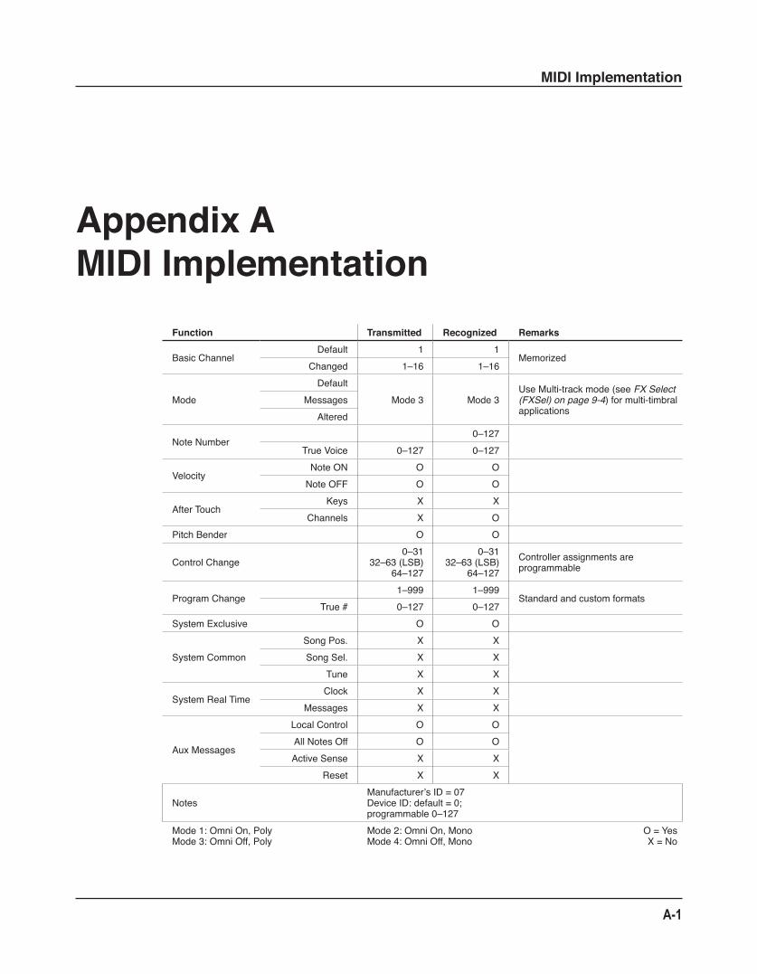
MIDI Implementation
A-1
Appendix AMIDI Implementation
Function Transmitted Recognized Remarks
BasicChannelDefault 1 1
MemorizedChanged 1–16 1–16
ModeDefault
Mode3 Mode3UseMulti-trackmode(seeFX Select (FXSel) on page 9-4)formulti-timbralapplications
MessagesAltered
NoteNumber0–127
TrueVoice 0–127 0–127
VelocityNoteON O ONoteOFF O O
AfterTouchKeys X X
Channels X OPitchBender O O
ControlChange0–31
32–63(LSB)64–127
0–3132–63(LSB)
64–127Controllerassignmentsareprogrammable
ProgramChange1–999 1–999
StandardandcustomformatsTrue# 0–127 0–127
SystemExclusive O O
SystemCommonSongPos. X XSongSel. X X
Tune X X
SystemRealTimeClock X X
Messages X X
AuxMessages
LocalControl O OAllNotesOff O OActiveSense X X
Reset X X
NotesManufacturer’sID=07DeviceID:default=0;programmable0–127
Mode1:OmniOn,PolyMode3:OmniOff,Poly
Mode2:OmniOn,MonoMode4:OmniOff,Mono
O=YesX=No

A-2
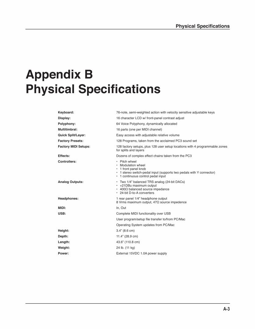
Physical Specifications
A-3
Appendix BPhysical Specifications
Keyboard: 76-note,semi-weightedactionwithvelocitysensitiveadjustablekeysDisplay: 16characterLCDw/front-panelcontrastadjustPolyphony: 64VoicePolyphony,dynamicallyallocatedMultitimbral: 16parts(oneperMIDIchannel)Quick Split/Layer: EasyaccesswithadjustablerelativevolumeFactory Presets: 128Programs,takenfromtheacclaimedPC3soundsetFactory MIDI Setups: 128factorysetups,plus128usersetuplocationswith4programmablezones
forsplitsandlayersEffects: DozensofcomplexeffectchainstakenfromthePC3Controllers: • Pitchwheel
• Modulationwheel• 1frontpanelknob• 1stereoswitch-pedalinput(supportstwopedalswithYconnector)• 1continuouscontrolpedalinput
Analog Outputs: • Two1/4”balancedTRSanalog(24-bitDACs)• +21DBumaximumoutput• 400Ωbalancedsourceimpedance• 24-bitD-to-Aconverters
Headphones: 1rearpanel1/4”headphoneoutput8Vrmsmaximumoutput,47Ωsourceimpedence
MIDI: In,OutUSB: CompleteMIDIfunctionalityoverUSB
Userprogram/setupfiletransferto/fromPC/MacOperatingSystemupdatesfromPC/Mac
Height: 3.4”(8.6cm)Depth: 11.4”(28.9cm)Length: 43.6”(110.8cm)Weight: 24lb.(11kg)Power: External15VDC1.0Apowersupply

A-4
Index
Index
AActivating Zones 7-6, 8-7Alphanumeric entry 3-9, 6-5, 7-5Audio cables 2-4, 12-3Aux effects 8-14Aux FX 8-14
BBank
Change 8-5, 9-5MIDI 8-5Select button 3-8
Bootloader (System Mode) 10-1Buttons
Chan/Param 3-6Control Select 3-5Function 3-2Object Select 3-7, 6-3, 7-3Value 3-6Zone 3-4, 7-6, 8-3
CChan/Param button 3-6Common parameters 8-2, 8-14Connecting Audio 2-4, 12-3Connecting MIDI 2-7, 12-4Connecting pedals 2-5, 12-5Continuous (control) pedals 2-3, 2-5, 2-6, 12-6Control Knob 3-5, 6-6, 7-7, 8-10
DDemo Function 3-11, 5-6Destination
Controller 8-10MIDI 8-4, 9-4
DialoguesHard Reset? 9-7Load All? 9-8
Save All? 9-7Double button presses 3-9
EEdit Setup Mode 5-2, 8-1Effects
Aux 8-14
FFiles
Deleting All 9-7Loading 9-8Saving 9-7
Format system flash memory 10-4Front panel 3-1Functions
Buttons 3-2Demo 3-11, 5-6Layer 5-4, 6-9, 7-9Split 5-4, 6-7, 7-8
FXAux 8-14
GGeneral MIDI
Velocity Map 9-4
HHard Reset 9-7
IID numbers
Controller destinations 8-10Programs 6-2Setups 7-2
KK2600 Bank mode 8-7Knob
Control 3-5, 6-6, 7-7, 8-10
LLayer Function 4-1, 5-4, 6-9, 7-9
Index
Loading files 9-8
MMIDI
Bank changes 8-5, 8-7, 9-5Channel 3-6, 6-10, 7-10, 8-4, 9-4Connecting 2-7, 12-4Implementation Chart A-1
ModesEdit Setup 5-2, 8-1Global 5-3, 9-1Program 5-1, 6-1Setup 5-2, 7-1System 5-3, 10-1
Mod Wheel 3-2, 8-10Muting Zones 7-6, 8-7
NNavigation 3-1Numeric entry 3-9
OObjects 4-1
Deleting all 9-7, 10-3Loading 9-8Organization 3-7, 4-2, 6-4, 7-3Programs 4-1, 6-1Saving 9-7Selecting 3-7, 6-3, 7-3Setups 4-1, 7-1
PPanic
Double button press 3-11Pedal A-3
Continuous (control) 1-2, 2-3, 2-6, 8-10, 12-6Switch 1-2, 2-2, 2-6, 8-13, 12-5
Pitch Wheel 3-2, 8-9Power cable 1-2, 2-3, 12-1Program Change 3-10, 5-5, 8-7Program Mode 5-1, 6-1Programs 4-1, 6-1
Editing 6-7Saving 6-10Table of 6-2
RReset
Hard 9-7
SSaving
All Objects 9-7Programs 6-10Setups 7-11, 8-15
SelectingModes 3-2, 5-1Objects 3-7, 6-3, 7-3
Setup Mode 5-2, 7-1Setups 4-1, 7-1
Editing 8-1Parameters 8-2Saving 7-11, 8-15Table of 7-2Zones 4-1, 7-5
Shift button 3-4, 7-6Sostenuto 2-5, 8-11Specifications A-3Split Function 4-1, 5-4, 6-7, 7-8Sustain 2-2, 2-5, 8-11Switch pedal 2-2, 2-5, 2-6, 12-5System Mode 5-3, 10-1
TTranspose
Buttons 3-4, 6-6, 7-6Zones 8-8
Tuning 9-3
UUpdate software 10-2USB Port 2-3, 10-2
VVelocity Maps 9-3
ZZones 7-5
Activating 7-6Muting 7-6Parameters 8-4