Music and Engineering: Amplifier Basics and Vacuum · PDF fileMusic and Engineering: Amplifier...
53
Music and Engineering: Amplifier Basics and Vacuum Tubes Tim Hoerning Fall 2008 (last modified 10/7/08)
Transcript of Music and Engineering: Amplifier Basics and Vacuum · PDF fileMusic and Engineering: Amplifier...

Music and Engineering:Amplifier Basics and Vacuum
TubesTim Hoerning
Fall 2008(last modified 10/7/08)

Overview• Classes of Amplifiers
– Linear – Classes A, B & AB– Switching – Class D
• Introduction to Vacuum Tubes– Thermionic Emission and the Edison Effect– Diodes, Triodes, Tetrodes and Pentodes– Common Tubes
• Common Vacuum Tube Circuits (not yet completed)– Power Supply section– Preamp– Phase Splitter– Power Amp– Reverb and Tremolo effects
Amplifier ClassesAmplifier Classes
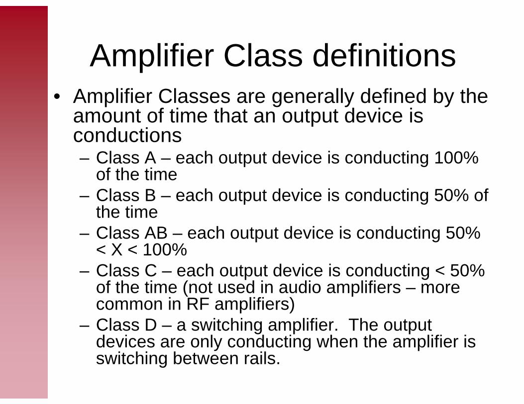
Amplifier Class definitions• Amplifier Classes are generally defined by the
amount of time that an output device is conductions– Class A – each output device is conducting 100%
of the time– Class B – each output device is conducting 50% of
the time– Class AB – each output device is conducting 50%
< X < 100%– Class C – each output device is conducting < 50%
of the time (not used in audio amplifiers – more common in RF amplifiers)
– Class D – a switching amplifier. The output devices are only conducting when the amplifier is switching between rails.
Class A
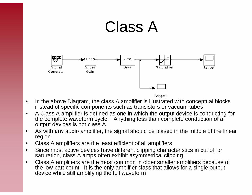
• In the above Diagram, the class A amplifier is illustrated with conceptual blocks instead of specific components such as transistors or vacuum tubes
• A Class A amplifier is defined as one in which the output device is conducting for the complete waveform cycle. Anything less than complete conduction of all output devices is not class A
• As with any audio amplifier, the signal should be biased in the middle of the linear region.
• Class A amplifiers are the least efficient of all amplifiers• Since most active devices have different clipping characteristics in cut off or
saturation, class A amps often exhibit asymmetrical clipping.• Class A amplifiers are the most common in older smaller amplifiers because of
the low part count. It is the only amplifier class that allows for a single output device while still amplifying the full waveform
31.3364
Sl iderGain
SignalGenerator
Scope1
ScopeSaturation
u+50
Bias

Class A Outputs
What is the problem with this output? Is it Class A?
What is the problem with this output? Is it Class A?
What is the problem with this output? Is it Class A?
What is the problem with this output? Is it Class A?
A correct class A output!
A correct class A output!

Class A Graphical Dynamic Transfer Function
• The graphical transfer function shows the input signal on the y-axis, and the output on the x-axis
• The curve above shows a class A amplifier with saturation.
Class B
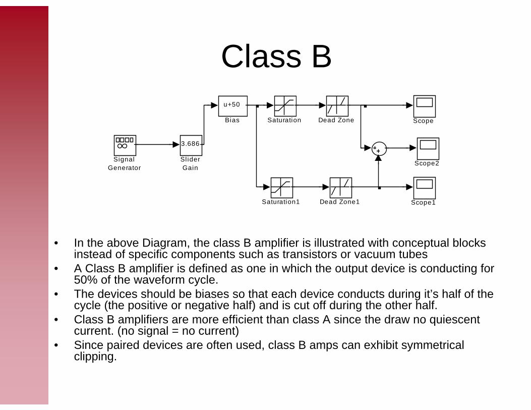
• In the above Diagram, the class B amplifier is illustrated with conceptual blocks instead of specific components such as transistors or vacuum tubes
• A Class B amplifier is defined as one in which the output device is conducting for 50% of the waveform cycle.
• The devices should be biases so that each device conducts during it’s half of the cycle (the positive or negative half) and is cut off during the other half.
• Class B amplifiers are more efficient than class A since the draw no quiescent current. (no signal = no current)
• Since paired devices are often used, class B amps can exhibit symmetrical clipping.
3.686
Sl iderGain
SignalGenerator
Scope2
Scope1
Scope
Saturation1
Saturation
Dead Zone1
Dead Zone
u+50
Bias

Class B Outputs
This is the output from the bottom
device
This is the output from the bottom
device
This is the output from
the top device
This is the output from
the top device
The combined output. Notice the crossover
distortion when neither
device is conducting.
The combined output. Notice the crossover
distortion when neither
device is conducting.

Class B Graphical Dynamic Transfer Function
• The graphical transfer function shows the input signal on the y-axis, and the output on the x-axis
• The curve above shows a class B amplifier with saturation and a dead-zone (a defining characteristic of a class B amplifier)

Class AB
• In the above Diagram, the class AB amplifier is illustrated with conceptual blocks instead of specific components such as transistors or vacuum tubes
• A Class AB amplifier is defined as one in which the output device is conducting for more than 50% but less than 100% of the waveform cycle.
• The devices should be biases so that each device conducts during it’s half of the cycle, plus a little more and is cut off during the majority of the other half.
• Class AB amplifiers are more efficient than class A, but not as efficient as class B. They draw some quiescent current.
• Class AB amplifiers are the most common in larger guitar amplifiers because of their efficiency.
• Tube amplifiers have two subtypes – AB1 – grid current never flows– AB2 – grid current flows for part of the cycle
1
Sl iderGain
SignalGenerator
Scope2
Scope1
Scope
Saturation1
Saturation
Dead Zone1
Dead Zone
u-1.4
Bias1
u+50.7
Bias

Class AB Outputs
This is the output from the bottom
device
This is the output from the bottom
device
This is the output from
the top device
This is the output from
the top device
The combined output. Notice
the lack of crossover distortion
when devices are not quite conducting
The combined output. Notice
the lack of crossover distortion
when devices are not quite conducting
Class D
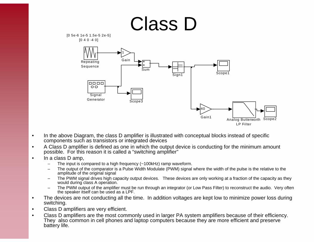
• In the above Diagram, the class D amplifier is illustrated with conceptual blocks instead of specific components such as transistors or integrated devices
• A Class D amplifier is defined as one in which the output device is conducting for the minimum amount possible. For this reason it is called a “switching amplifier”
• In a class D amp, – The input is compared to a high frequency (~100kHz) ramp waveform. – The output of the comparator is a Pulse Width Modulate (PWM) signal where the width of the pulse is the relative to the
amplitude of the original signal– The PWM signal drives high capacity output devices. These devices are only working at a fraction of the capacity as they
would during class A operation.– The PWM output of the amplifier must be run through an integrator (or Low Pass Filter) to reconstruct the audio. Very often
the speaker itself can be used as a LPF.• The devices are not conducting all the time. In addition voltages are kept low to minimize power loss during
switching.• Class D amplifiers are very efficient. • Class D amplifiers are the most commonly used in larger PA system amplifiers because of their efficiency.
They also common in cell phones and laptop computers because they are more efficient and preserve battery life.
[0 5e-6 1e-5 1.5e-5 2e-5][0 4 0 -4 0]
Sum
SignalGenerator
Sign1
Scope3
Scope2
Scope1
RepeatingSequence
40
Gain1
1
Gain
Analog ButterworthLP Fi l ter
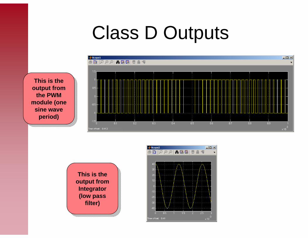
Class D Outputs
This is the output from Integrator (low pass
filter)
This is the output from Integrator (low pass
filter)
This is the output from
the PWM module (one
sine wave period)
This is the output from
the PWM module (one
sine wave period)
Vacuum TubesVacuum Tubes
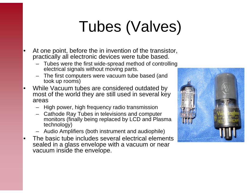
Tubes (Valves)• At one point, before the in invention of the transistor,
practically all electronic devices were tube based.– Tubes were the first wide-spread method of controlling
electrical signals without moving parts.– The first computers were vacuum tube based (and
took up rooms)• While Vacuum tubes are considered outdated by
most of the world they are still used in several key areas
– High power, high frequency radio transmission– Cathode Ray Tubes in televisions and computer
monitors (finally being replaced by LCD and Plasma technology)
– Audio Amplifiers (both instrument and audiophile)• The basic tube includes several electrical elements
sealed in a glass envelope with a vacuum or near vacuum inside the envelope.
Thermionic Emission and the Edison Effect
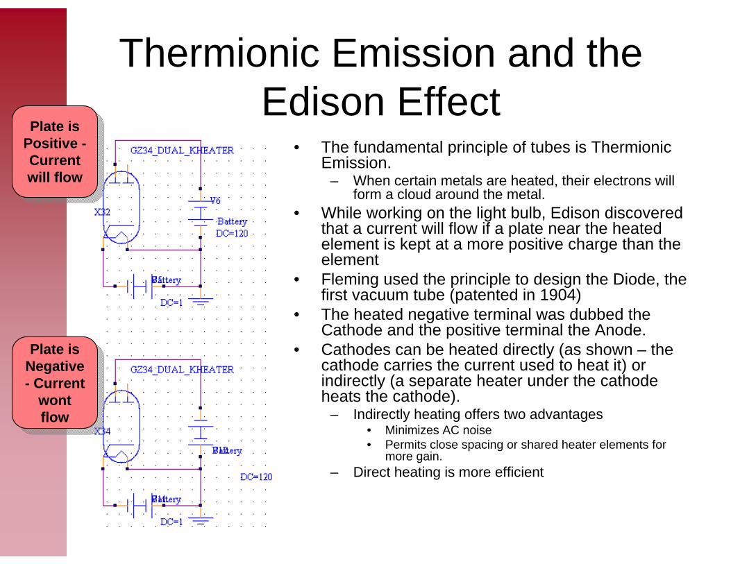
• The fundamental principle of tubes is Thermionic Emission.
– When certain metals are heated, their electrons will form a cloud around the metal.
• While working on the light bulb, Edison discovered that a current will flow if a plate near the heated element is kept at a more positive charge than the element
• Fleming used the principle to design the Diode, the first vacuum tube (patented in 1904)
• The heated negative terminal was dubbed the Cathode and the positive terminal the Anode.
• Cathodes can be heated directly (as shown – the cathode carries the current used to heat it) or indirectly (a separate heater under the cathode heats the cathode).
– Indirectly heating offers two advantages• Minimizes AC noise• Permits close spacing or shared heater elements for
more gain.– Direct heating is more efficient
Plate is Positive -Current will flow
Plate is Positive -Current will flow
Plate is Negative - Current
wont flow
Plate is Negative - Current
wont flow

Diode • Tube Diodes work the same as solid state diodes
– Current only flows when the Anode (or plate in vacuum tube terminology) is has a positive voltage relative to the cathode
– In most rectification circuits the Plate is attached to the power transformer and the cathode to the DC power supply section (see handouts for schematics)
• Diodes are available with multiple configuration options
– 1 or 2 plates (for half or full wave rectification) – 1 or 2 cathodes (in conjunction with 1 or 2 plates, but in
varying combinations)– Directly or indirectly heated
• Full Wave rectification is generally performed with a single 2 plate tube and a center tapped power transformer.
• Some Commons Tubes– 35W4 – indirectly heat half wave rectifier– 5Y3GT – directly heated full wave rectifier

Diode – Electron Issues
• Not all electrons flow to the anode– Some return to the cathode– Some stay in the air as a “space charge”
• The Space Charge has a repelling force on other electrons
• Can reduce the Space Charge in a few ways– A higher plate voltage will improve the
number of electrons reaching the plate– Reducing the distance between the
cathode and the plate will help• At the saturation point, all available
electrons will flow from the cathode to the anode.– This saturation current is called the
“emission current”

Triode • First electronic device to allow voltage to control current
flow with a continuous range.• A “control grid” is built between the cathode and the
plate. (the “grid” is actually a loosely wrapped spiral cage)
• The voltage on the grid determines the amount of current that flows through the plate.
– If it’s very negative (relative to the cathode), then no current flows to the plate.
– The more positive the signal, the more current flows.– By applying an appropriate negative bias to the grid to
center an AC signal in the usable output range of the tube, one can create a simple amplifier stage
• These metal elements in the tube have inter-element capacitances
– The grid to plate capacitance is the most important– This can produce coupling between elements.
• Grid to Plate coupling could cause instability in power output stages
• Some Common Tubes– Not many – most triodes are combined with other elements
(more on this later)– 6C4 – indirectly heated power triode– 6AV6 – high mu triode w/ a twin diode– 12BF6 – med mu triode w/ a twin diode
For what solid state device have you used the word triode used to describe?
For what solid state device have you used the word triode used to describe?

Twin Triode • As circuits got more complex, multiple
triodes (and later other tube devices) were enclosed in the same glass envelope to save more.
• One of the more common tubes used in audio amplifies is a twin triode - two independent triodes in the same glass envelope.
• Heaters can be shared or independent– Independent heaters can be run in series or
parallel• Common Tubes
– 6SN7GT – Med-mu indirectly heated twin triode with an octal base
– 12AU7 – med mu indirectly heated twin triode with a 9 pin mini base
– 12AX7 – high mu indirectly heated twin triode with a 9 pin min base. Pin compatible with the 12AU7 and 12AT7

Tetrode• As the name implies, a tetrode has an
additional element.• The “screen grid” was added to reduce
the control grid to plate capacitance– It acts as a electrostatic shield to reduce
capacitance by a factor of 100.– The spacing between the wires is large – A high voltage is put on the screen grid
• This attracts some electrons, but most reach the plate
• Plate voltage itself becomes less important.• As long as VP > VSG, the plate current
depends more on VSG. • Since current is largely independent of VP, it
is possible to get more amplification and less grid to plate feedback
• Equivalent to using transistors in Cascode configuration
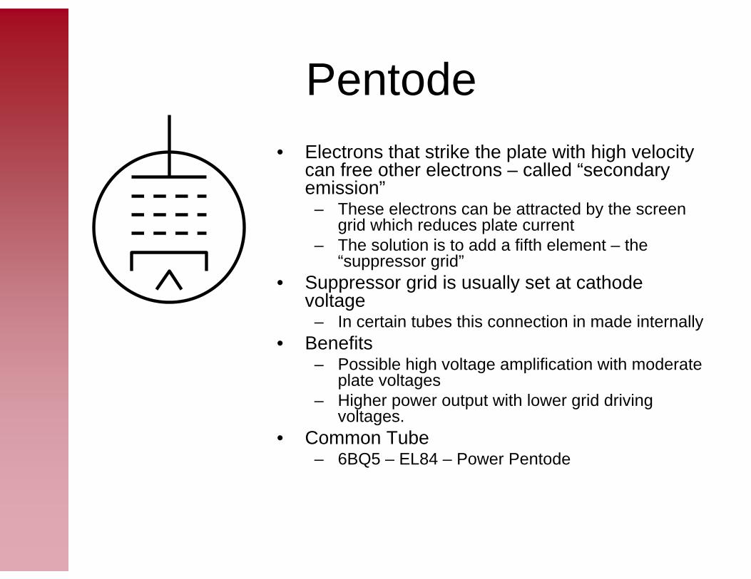
Pentode • Electrons that strike the plate with high velocity
can free other electrons – called “secondary emission”
– These electrons can be attracted by the screen grid which reduces plate current
– The solution is to add a fifth element – the “suppressor grid”
• Suppressor grid is usually set at cathode voltage
– In certain tubes this connection in made internally• Benefits
– Possible high voltage amplification with moderate plate voltages
– Higher power output with lower grid driving voltages.
• Common Tube– 6BQ5 – EL84 – Power Pentode
Beam Power Tubes• Beam confine electrons to a area less than
360 degrees. • Usually the CG and SG wires are lined up to
minimize current in SG.• Beam confining electrodes are used to define
the beam and reduce secondary emissions• Common tubes
– 6L6GT – Beam Pentode– 50L6GT – Beam Pentode– 6AQ5A – Beam Pentode

Bases
• The current landscape has simplified to two predominant bases– Octal – 8 large pins with a phenolic base including a locating tab to
align the tube in the socket (shown on right above)– 9 pin miniature – 9 small wire pins. Bottom of tube has room for 10
pins, but the missing pin serves as an alignment device. (shown on left above)
• In the long history of tubes many other bases have come and gone before and after the octal and 9 pins. They just didn’t have the longevity– The earliest vacuum tubes use a four thick pin base
• Some have an additional wire that runs to the top of the tube– Later experiments in multi circuit tubes led to other layouts
• The 11 pin compactron 6U10 features 3 triodes in one envelopes (used by Ampeg in the 70s)
• The Nuvistor was miniture “high-technology” before the solid state devices dominated the market

Tube Characteristics
• Tubes have both Static and Dynamic Characteristics– Static Characteristics are shown on plate
characteristics and mutual characteristics curves. See curves in “Electron Tube Characteristics”chapter of RCA tube manual
– Dynamic Characteristics include• Amplification Factor• Plate resistance• Plate transconductance
Dynamic Characteristics• Amplification factor – mu – μ
– The ratio of the change in plate voltage to a change in control voltage (in the opposite direction) given that the plate currentremains unchanged
• Ex. A 0.1 control voltage changed produces a 1 volt plate voltage change given a mu of 10
• Plate Resistance rp– Resistance of the path between the cathode and plate to alternating
current.– rp = Change in voltage @ plate / change in plate current measured.– Expressed in ohms
• Transconductance - gm– Transconductance = mu / rp– Specifies the ratio of plate current output change relative to a
change in voltage on the control grid.– Measured in mhos
• Plate Efficiency– The ratio of the AC power output to the produce of the DC plate
voltage and DC plate current. i.e. a ratio of the AC power to the DC power
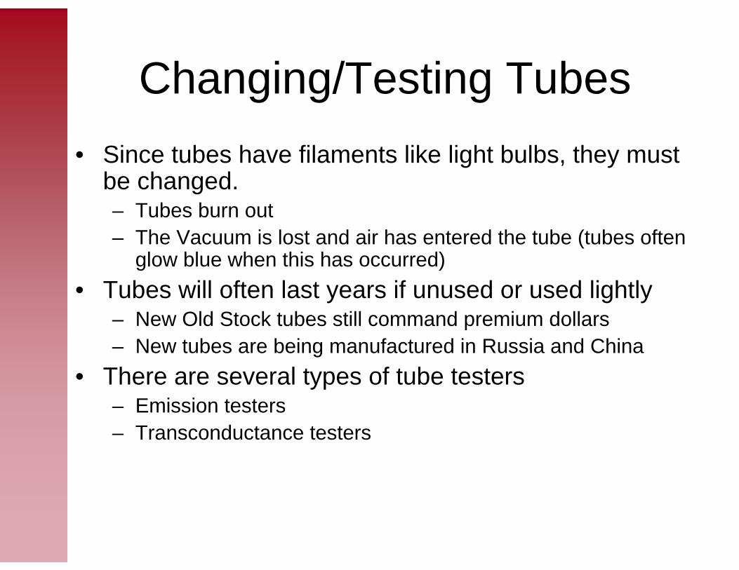
Changing/Testing Tubes• Since tubes have filaments like light bulbs, they must
be changed.– Tubes burn out– The Vacuum is lost and air has entered the tube (tubes often
glow blue when this has occurred) • Tubes will often last years if unused or used lightly
– New Old Stock tubes still command premium dollars– New tubes are being manufactured in Russia and China
• There are several types of tube testers– Emission testers– Transconductance testers

Emission Testers
• The above two testers determine the emission output of the tube.
• They can determine the quality and approximate life left, but can’t measure the operating characteristics of the tube
• The switches connect the pins of the tubes to their respective circuit elements (heater, cathode, plate voltage supply, etc)

Transconductance Testers
• Hickok testers are considered some of the best tube testers • They can measure the transconductance of the tube.
– This is critical for matching output tubes into pairs and quartets• The rotary switches connect the pins of the tubes to their
respective circuit elements (heater, cathode, plate voltage supply, etc)– The guide for the switches is contained in the roll chart on the
bottom of the tester– The gauge is calibrated in micro-mhos.
Vacuum Tube AmplifierVacuum Tube Amplifier

Power Suplies• The power supplies in most tube amplifier can
be considered in two parts– The heater power supply
• Usually AC, but can be DC for reduced noise• 6.3 VAC is the most common
– Many tubes such as the 6V6 or 6L6 use 6 volt heaters– Other tubes such as the 12AX7 use a 12 volt heater supply
if the dual filaments are run in series, but can use a 6.3 volt heater when the elements are run in parallel.
– The high voltage power supply generally comes from a step up transformer
• Power supplies can reach into the 500 Volt range• DC can be rectified via solid state or tube diodes
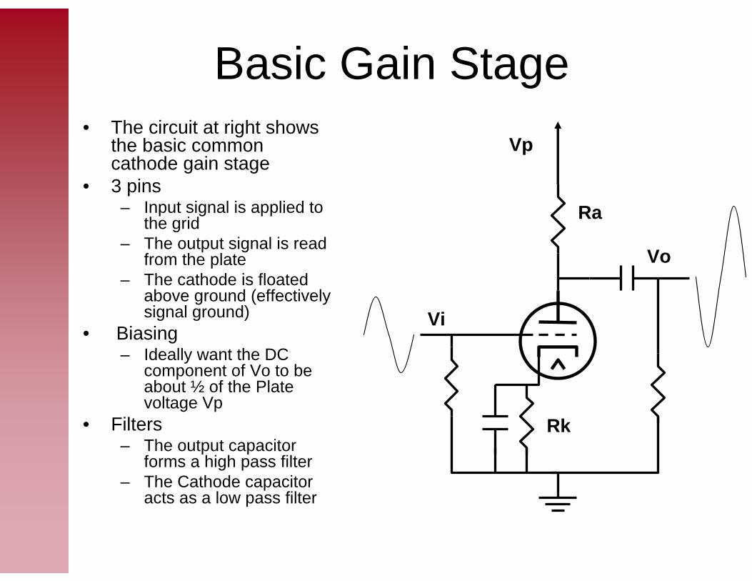
Basic Gain Stage • The circuit at right shows
the basic common cathode gain stage
• 3 pins– Input signal is applied to
the grid– The output signal is read
from the plate– The cathode is floated
above ground (effectively signal ground)
• Biasing– Ideally want the DC
component of Vo to be about ½ of the Plate voltage Vp
• Filters– The output capacitor
forms a high pass filter– The Cathode capacitor
acts as a low pass filter
Vp
Vo
Vi
Ra
Rk
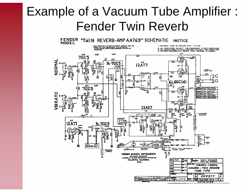
Example of a Vacuum Tube Amplifier : Fender Twin Reverb
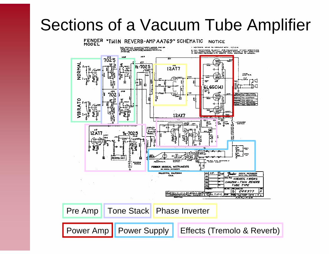
Sections of a Vacuum Tube Amplifier
Pre Amp Tone Stack Phase Inverter
Power Amp Power Supply Effects (Tremolo & Reverb)
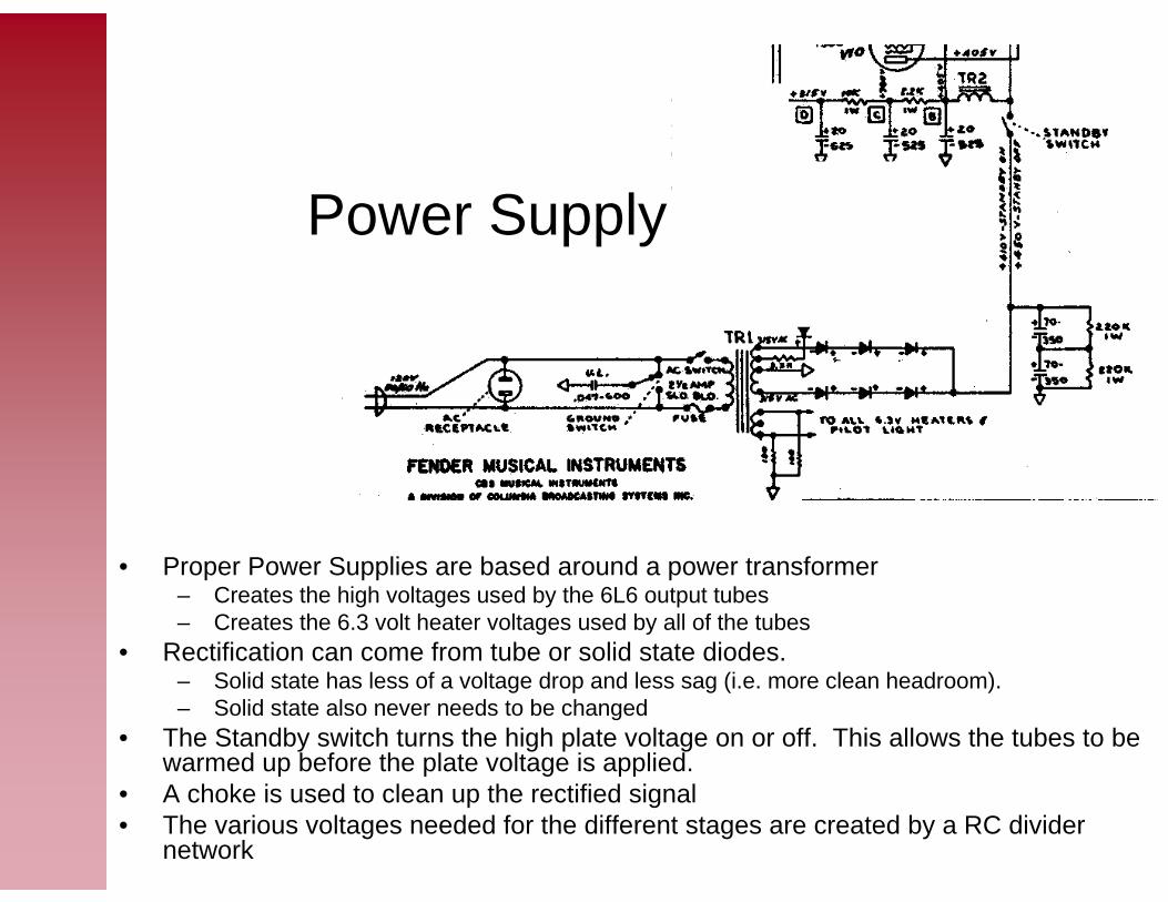
• Proper Power Supplies are based around a power transformer– Creates the high voltages used by the 6L6 output tubes– Creates the 6.3 volt heater voltages used by all of the tubes
• Rectification can come from tube or solid state diodes.– Solid state has less of a voltage drop and less sag (i.e. more clean headroom).– Solid state also never needs to be changed
• The Standby switch turns the high plate voltage on or off. This allows the tubes to be warmed up before the plate voltage is applied.
• A choke is used to clean up the rectified signal• The various voltages needed for the different stages are created by a RC divider
network
Power Supply

Pre Amplifier• Traditional Fender amplifiers
have two independent channels with two independent inputs. Other amplifiers have one input and “channel switching” to get different sounds
• A 7025 dual triode is used for the first two gain stages
• The first gain stage boosts the incoming signal and feeds it through the passive tone stack
• The second stage boosts the signal that was attenuated by the tone stack
• “High-gain” amplifiers use additional gain stages to get a more heavily distorted sound
– Each stage provides a small amount of non-linearity to the signal.
– Multiple non-linear stages have a different sound than a single clipping stage
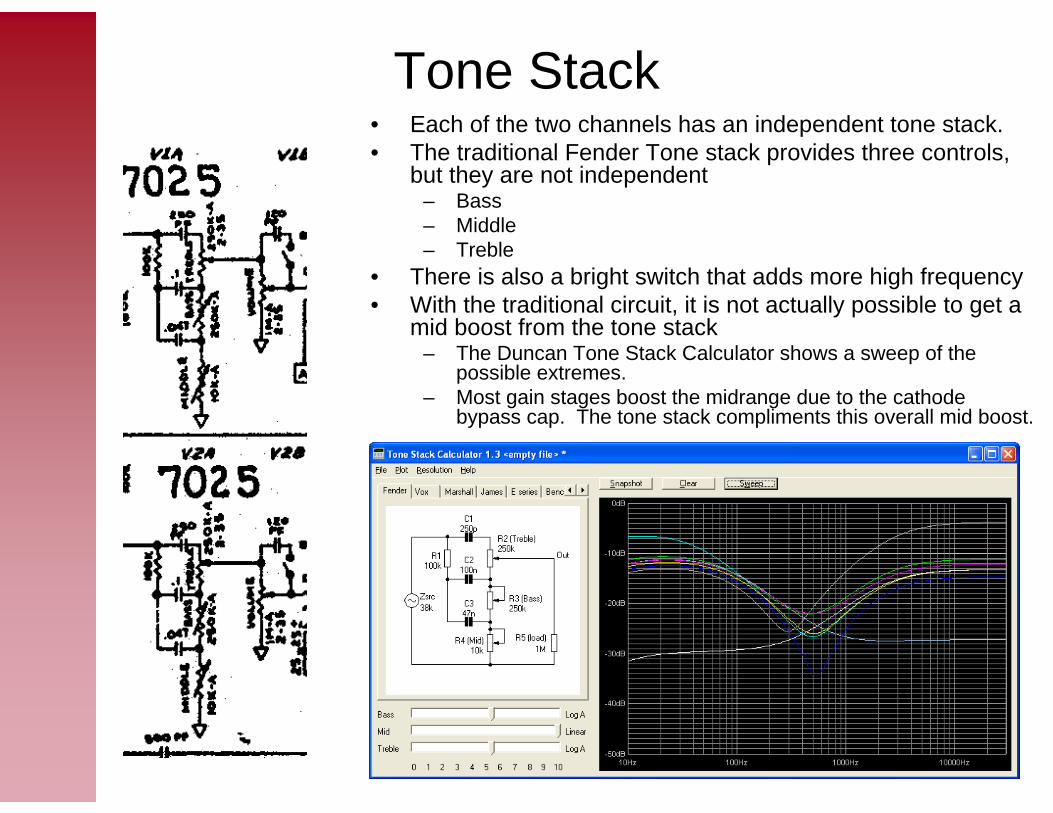
Tone Stack• Each of the two channels has an independent tone stack.• The traditional Fender Tone stack provides three controls,
but they are not independent– Bass– Middle– Treble
• There is also a bright switch that adds more high frequency• With the traditional circuit, it is not actually possible to get a
mid boost from the tone stack– The Duncan Tone Stack Calculator shows a sweep of the
possible extremes.– Most gain stages boost the midrange due to the cathode
bypass cap. The tone stack compliments this overall mid boost.

Phase Inverter
• In order to drive a push-pull output stage a phase inverter (or phase splitter) must be used to create two signals 180 degrees out of phase.
• This amplifier uses a long tailed pair phase inverter with negative feedback from the power amplifier to linearize the overall transfer function
• The long tailed pair operates as a differential amplifier to provide gain in additional to creating complimentary phase signal.

Power Amplifier• This power amplifier uses a quartet
of 6L6GC tubes operating as a Class AB amplifier
• The top two operate in parallel on the positive side of the signal.
• The bottom tow operate on the negative side of the signal
• Almost all tube amplifiers require a output transformer to couple the low impedance speakers to the tube circuit that requires a high impedance load
• This power amplifier uses a “fixed-bias” reference
– A bias voltage is applied to the grid to place the tube in the correct operating range
– Biasing the tube “too hot” causes more overlap between the sections and a greater quiescent current
– Biasing the tube “too cold” causes more cross over distortion

Effects: Tremolo & Reverb
• Older amplifiers often have one or two effects:– Reverb
• Meant to sound like the natural reverberation in a hall or cavern• Created by coupling signal into a spring inside a pan. The reflections of the signal in
the pan create the reverb sound• Extra gain stages are required to drive the reverb pan and amplify the signal again after
passing through the tank.– Tremolo
• Provides rhythmic oscillation of the amplitude of the input signal• Often mislabeled as vibrato on Fender amplifiers (there is some debate as to whether
this was a mistake on Leo Fender’s part or an attempt to grab potential buyers from Magnatone amplifiers which did have a true pitch vibrato)
• The Low Frequency Oscilator generates a sign wave that is below 20Hz (often in the 0.5 to 10Hz range).
• The modulates the amplitude of the input signal via – Bias voltage (as in this amp)– An Opto Isolator acting as a variable resistance element (used in this schematic)

Example 2: Fender Vibro Champ
Pre Amp Tone Stack Phase Inverter
Power Amp Power Supply Effects (Tremolo)
Why is there no phase inverter?

• Notice the Power Supply section on the primary side of the powertransformer
• The two prong power is connected to the primary.• The “death cap” can be tied to either of the two prongs to attempt to give the
chassis a ground reference – ideally it would be tied to the neutral, but
• the 2 prong could be plugged in wrong • The outlet could be wired wrong• hence the switch
– The “death cap” earned it’s name because with age, it often shorts our and tie one of the power legs directly to chassis ground
• The correct way to replace a 2 prong cord is to use a 3 prong grounded cord
– Remove the death cap and ground switch– The Hot pin is connected to one end of the primary side of the power transformer– The Neutral pin is connected to the other end of the primary side of the power
transformer– The Ground pin is wired to the chassis ground.
Three Prong Conversion

Widow Maker Amps• In addition to 2 prong cords, many of the cheaper old tube amps
are of the “Widowmaker” variety• A widowmaker amplifier is indentified by it’s lack of a power
transformer– All the tubes use low plate voltages, obtainable without stepping up
the high voltage– Non 6 or 12 volt heaters
• All the tubes require more voltage for their heaters (typically 25,35 or 50 volts)
• All the heaters are run in series• Typically the sum of all the heater voltages is approximately 110Volts.
– Because there is now power transformer, it is not possible to do a three prong conversion without installing a power transformer.
– Some widowmaker-like amps have the normal heater characteristics of a widowmaker, but have a 1:1 power transformer
• These may be safely converted to three prong.

Example Widowmaker
25 volt heater voltages
All heaters in seriesSum of heaters is 25+25+25+25+6+6 = 112
No Power Transformer!
Demos
• Cut open tubes• Tube amp (Vibro-Champ)• Books (Tube Amp Book, TUT)
References[RCA70] RCA Receiving Tube Manual – 1970 edition RC-27[Pit93] Pittman, Aspen The Tube Amp Book, 4th Edition Groove Tubes

Online Resources• http://en.wikipedia.org/wiki/Thermionic_emission
– Wikipedia article on Thermionic emission.• http://en.wikipedia.org/wiki/Vacuum_tube
– Wikipedia article on the Vacuum Tube• http://en.wikipedia.org/wiki/Electronic_amplifier
– Wikipedia article on electronic amplifiers
To be continued …To be continued …
Everything after this are just notes or drafts
Everything after this are just notes or drafts

Small Signal Circuit model

Biasing an Amplifier
Tone Stacks

Comparison to Transistors