MURELLE EQUIPE 220-550 BOX - simehellas.gr¤ΕΧΝΙΚΟ...NOTE: The installation must incorporate a...
56
MURELLE EQUIPE 220-550 BOX Installation and servicing instructions 199838 UK ENSURE THAT THESE INSTRUCTIONS ARE LEFT FOR THE USER Please read the Important Notice within this guide regarding your boiler warranty
-
Upload
nguyenkhuong -
Category
Documents
-
view
215 -
download
1
Transcript of MURELLE EQUIPE 220-550 BOX - simehellas.gr¤ΕΧΝΙΚΟ...NOTE: The installation must incorporate a...

MURELLE EQUIPE 220-550 BOX
Installation and servicing instructions
199838
UKENSURE THAT THESE INSTRUCTIONS ARE LEFT
FOR THE USER
Please read the Important Notice within this guide regarding your boiler warranty

All descriptions and illustrations provided in this manual have been carefully prepared but we reserve the right to make changes and improvements in our products that may affect the accuracy of the information contained in this manual.
This boiler may require 2 or more operatives to move it into its installation site, remove it from its packaging and during movement into its installation location. Manoeuvring the boiler may include the use of a sack truck and involve lifting pushing and pulling.Caution should be exercised during these operations.
Operatives should be knowledgeable in handling techniques when performing these tasks and the following precautions should be considered:– Grip the boiler at the base– Be physically capable– Use personal protective equipment as appropriate e.g. gloves, safety footwear.
During all manoeuvres and handling actions, every attempt should be made to ensure the following unless unavoidable and/or the weight is light.– Keep back straight– Avoid twisting at the waist– Always grip with the palm of the hand– Keep load as close to the body as possible– Always use assistance
WARNINGCaution should be exercised when performing any work on this appliance.Protective gloves and safety glasses are recommended.– Avoid direct contact with sharp edges.– Avoid contact with any hot surfaces.
NOTICEPlease be aware that due to the wet testing of the appliance, there may some residual water in the hydraulic circuit.– Protect any surfaces, carpets or floorings.– Use a suitable container to catch any water that escape when removing the protective caps from the connections.
SAFE HANDLING

Important InformationIT IS A STATUTORY REQUIREMENT THAT ALL GAS APPLIANCES ARE INSTALLED BY COMPETENT PERSONS, IN ACCORDANCE WITH THE GAS SAFETY (INSTALLATION AND USE) REGULATIONS (CURRENT EDITION). The manufacturer’s instructions must not be taken as overriding any statutory requirements, and failure to comply with these regulations may lead to prosecution.
No modifications to the appliance should be made unless they are fully approved by the manufacturer.
GAS LEAKS: DO NOT OPERATE ANY ELECTRICAL SWITCH, OR USE A NAKED FLAME. TURN OFF THE GAS SUPPLY AND VENTILATE THE AREA BY OPENING DOORS AND WINDOWS contact the gas emergency service on 0800111999.
CONTENTS
1 DEVICE DESCRIPTION . . . . . . . . . . . . . . . . . . . . . . . . . . . . . . . . . . . . . . . . . . . . . . . . . . . . . . . . . . . . . . . . . . . . . . . . . . . . . . . . pag. 42 INSTALLATION . . . . . . . . . . . . . . . . . . . . . . . . . . . . . . . . . . . . . . . . . . . . . . . . . . . . . . . . . . . . . . . . . . . . . . . . . . . . . . . . . . . . . . . pag. 103 CHARACTERISTICS . . . . . . . . . . . . . . . . . . . . . . . . . . . . . . . . . . . . . . . . . . . . . . . . . . . . . . . . . . . . . . . . . . . . . . . . . . . . . . . . . . pag. 234 COMMISSIONIMG, USE AND MAINTENANCE . . . . . . . . . . . . . . . . . . . . . . . . . . . . . . . . . . . . . . . . . . . . . . . . . . . . . . . . . pag. 305 FAULT FINDING . . . . . . . . . . . . . . . . . . . . . . . . . . . . . . . . . . . . . . . . . . . . . . . . . . . . . . . . . . . . . . . . . . . . . . . . . . . . . . . . . . . . . . pag. 40 APPENDIX 1 . . . . . . . . . . . . . . . . . . . . . . . . . . . . . . . . . . . . . . . . . . . . . . . . . . . . . . . . . . . . . . . . . . . . . . . . . . . . . . . . . . . . . . . . . pag. 41
IPX4D
Please refer to commissioning instructions for filling in the checklist at the back of this installation guide.Note: All Gas Safe registered installers carry a ID Card.
You can check your installer is Gas Safe Registered by calling 0800 408 5577
IMPORTANT
Prior to switching on the boiler for the first time, check the following:– Make sure that there are no liquids or inflammable materials in the immediate vicinity of the boiler.– Make sure that the electrical connections have been made correctly and that the earth wire is connected to a
good earthing system.– Ensure that tightness and let by test have been conducted, including the internal gas pipe work.– Make sure that the boiler is set for operation for the type of gas supplied.– Check that the flue pipe for the outlet of the products of the combustion is unobstructed and has been properly
installed.– Make sure that any isolation valves are open.– Make sure that the system is filled with water and is thoroughly vented.– Check that the circulating pump is not jammed.– Purge the gas supply pipe work.– Ensure that the checklist is filled in when the commissioning has been completed.

4
1.1 INTRODUCTION
“MURELLE EQUIPE 220-330-440-550 BOX” are pre-mixed condensation heating
modules intended only for heating, designed to work in sequence/cascade. They are designed and constructed to meet European directives 2009/142/
CEE, 2004/108/CEE, 2006/95/CEE and 92/42/CEE.
1 DEVICE DESCRIPTION
1.2 DIMENSIONS MODULES
1.2.1 “MURELLEEQUIPE 220 BOX”
Fig. 1
FIXTURESM System supply (Flange PN6-DN100)R System return (Flange PN6-DN100)G Gas (Flange PN6-DN50) S3 Condensation drain ø 40
90
180
156396
790
567
272
S3
G
M
307
777
R
260380 1100
648
1600
2010
470 390
NOTE: The installation must incorporate a hydraulic separator or plate heat exchanger. The hydraulic separator available from Sime Ltd is supplied with modules in a kit code 8101552 and the tubes connecting the hydraulic separator in the kit code 8101532. It can be assembled on the left-hand side by moving the system supply/return manifold blind flanges.

5
1.2.2 “MURELLE EQUIPE 330 BOX”
90
180
156396
790
567
272
S3
G648
1600
2010
390630470
1730380 260
307
777
M
R
1100 630
Fig. 1/a
FIXTURESM System supply (Flange PN6-DN100)R System return (Flange PN6-DN100)G Gas (Flange PN6-DN50) S3 Condensation drain ø 40
NOTE: The installation must incorporate a hydraulic separator or plate heat exchanger. The hydraulic separator available from Sime Ltd is supplied with modules in a kit code 8101552 and the tubes connecting the hydraulic separator in the kit code 8101532. It can be assembled on the left-hand side by moving the system supply/return manifold blind flanges.

6
1.2.3 “MURELLE EQUIPE 440-550 BOX”
180
790396
156
567
90
272 56
2
1197
S3
M
R
G
1600
2010
2830590500
390630470630470
635
562
MURELLE EQUIPE 440 BOX
180
790396
156
567
90
272 56
2
1197
S3
M
R
G
1600
2010
2200590500
390470630470
635
562
MURELLE EQUIPE 550 BOX
Fig. 1/a
FIXTURESM System supply (Flange PN6-DN100)R System return (Flange PN6-DN100)G Gas (Flange PN6-DN50) S3 Condensation drain ø 40
NOTE: The installation must incorporate a hydraulic separator or plate heat exchanger. The hydraulic separator available from Sime Ltd is supplied with modules in a kit code 8101553 and the tubes connecting the hydraulic separator in the kit code 8101533. It can be assembled on the left-hand side by moving the system supply/return manifold blind flanges.

7
1.3 TECHNICAL SPECIFICATIONS
MURELLE EQUIPE 220 BOX 330 BOX 440 BOX 550 BOX
Nominal heat output (80-60°C) kW 210.8 316.2 421.6 527.0
Nominal heat output (50-30°C) kW 225.2 337.8 454.0 563.0
Minimum heat output (80-60°C) kW 20.8 20.8 20.8 20.8
Minimum heat output (50-30°C) kW 23.6 23.6 23.6 23.6
Nominal heat input kW 216 324 432 540
Minimum heat input kW 21.6 21.6 21.6 21.6
Min-max operating yield (80-60°C) % 96.4-97.6 96.4-97.6 96.4-97.6 96.4-97.6
Min-max operating yield (50-30°C) % 107.4-104.2 107.4-104.2 107.4-104.2 107.4-104.2
Operating yield at 30% (40-30°C) % 102.0 102.0 102.0 102.0
Energy yield markings (CEE 92/42) ´´´´ ´´´´ ´´´´ ---
Generators with a heat output kW 105.4 n° 2 3 4 5
Exhaust temperature at max flow rate (80-60°C) °C 64 64 64 64
Exhaust temperature at min flow rate (80-60°C) °C 51 51 51 51
Exhaust temperature at max flow rate (50-30°C) °C 45 45 45 45
Exhaust temperature at min flow rate (50-30°C) °C 40 40 40 40
Smokes flow min/max g/s 37/372 37/558 37/744 37/930
CO2 at max/min flow rate G20 % 9.0/9.0 9.0/9.0 9.0/9.0 9.0/9.0
CO2 at max/min flow rate G31 % 10.2/10.2 10.2/10.2 10.2/10.2 10.2/10.2
Feeding tension V-Hz 230-50 230-50 230-50 230-50
Absorbed power consumption W 618 927 1236 1545
Electrical protection grade IPX4D IPX4D IPX4D IPX4D
Max. output pressure fumes manifold Pa 375 375 375 375
Max. pressure independent fumes Pa 428 428 428 428
CE certification n° 1312CM5621 1312CM5621 1312CM5621 1312CM5621
Category II2H3P II2H3P II2H3P II2H3P
Category in France I2Er3P I2Er3P I2Er3P I2Er3P
Type B23-53/B23P-53P B23-53/B23P-53P B23-53/B23P-53P B23-53/B23P-53P
NOx class 5 5 5 5
HEATING
Max operating pressure bar 5 5 5 5
Max operating temperature °C 85 85 85 85
Water content modules l 36.3 55.9 72.6 92.2
Single module temperature regulation °C 20/80 20/80 20/80 20/80
GAS AND NOZZLE PRESSURE
Supply pressure G20/G25 mbar 20/25 20/25 20/25 20/25
Supply pressure G31 mbar 37 37 37 37
Number of nozzles n° 2 3 4 5
Nozzle diameter G20/G25 ø 12.4 12.4 12.4 12.4
Nozzle diameter G31 ø 8.2 8.2 8.2 8.2
Consumption at nominal output G20 m3/h 22.84 34.26 45.68 57.10
Consumption at minimum output G20 m3/h 2.28 2.28 2.28 2.28
Consumption at nominal output G31 kg/h 16.76 25.14 33.52 41.90
Consumption at minimum output G31 kg/h 1.68 1.68 1.68 1.68
WEIGHT kg 380 615 760 995

8
1.4 OPERATING DIAGRAM (fig. 2)
M
R
1
2 25
23
22G
26
12
1614
15
18
2427
6
8
109
11
17S3
530
Fig. 2
KEY
1 Cascade delivery supply probe (SMC) 2 Hydraulic compensator 3 Antifreeze siphon sensor (SB/SA) 4 Safety valve 5 bar 5 Condensation drain siphon 6 Gas valve 7 8 litre expansion tank 8 Fan 9 Heating supply probe (SM) 10 Safety thermostat 95°C 11 Exhaust temperature probe (SF) 12 Heat exchanger13 Gas isolation valve 14 Heating return probe (SR) 15 Water pressure transducer
16 Air release vent 17 Non return valve 18 Shunt pump 19 3-way isolation/drain valve 20 Isolation valve 21 Single module drain
FIXTURESM System supplyR System returnG GasS3 Condensation drain

9
1
2
3
4
5
6
7
8
9
10
111213
14
15
1617
1.5 MAIN COMPONENTS (fig. 3)
Fig. 3
Code 8111161Model MURELLE EQUIPE 220 BOXSerial n. 9999999999
PAR 1 = 8 (G20) / 16 (G31)PAR 2 = 9
KEY 1 System return manifold 2 Gas isolation valve 3 System supply manifold 4 Gas valve 5 Fan 6 Ignition electrode 7 Primary exchanger 8 Ignition transformer 9 Control panel 10 Heating return probe (SR) 11 Heating supply probe (SM)12 Safety thermostat 95°C13 Ionisation electrode14 Shunt pump15 Isolation valve16 3-way isolation/drain valve17 Gas manifold
10
The unit is suitable for external installation in a fixed location.It must be installed by qualified engineers in compliance with all instructions con-tained in this manual. Furthermore, the installation must be in accordance with current standards and regulations.
2.1 SUPPLY (fig. 4)
“MURELLE EQUIPE 110 BOX” heat mod-ules are available in single or double gen-erators and can be coupled together to a maximum of 5 generators. The cabinet is pre painted, zinc coated. They are supplied complete with flow and return, gas and condensate manifolds, external tempera-ture probe kit, cascade supply and RS-485 code 8092250 board connection cable. Available separately:– Connection kit for the hydraulic separa-
tor code 8101532 for modules “220-330 BOX” and code 8101533 for modules “440-550 BOX”
– Double box (size: 1100 x 790 x 1600) for hydraulic separator code 8101527
– Hydraulic separator kit code 8101552 for modules “220-330 BOX” and code 8101553 for modules “440-550 BOX”
– Polypropylene exhaust manifold kit for indoor installation (purposely treated to resist weathering when installed out-doors):
code 8102530 for “220 BOX” module code 8102531 for “330 BOX” module code 8102532 for “440BOX” module code 8102533 for “550 BOX” module– Exhaust terminal code 8089530 (1 per
generator) for outdoor installations.
To electrically connect the modules and to assemble the exhaust for indoor or outdoor installations, see points 2.6, 2.7 and 2.10
in this manual.
2.2 INSTALLATION
2.2.1 Indoors
“MURELLE EQUIPE 220-330-440-550 BOX” heat modules can be installed in boil-er rooms whose size and requirements meet current regulations.
VENTILATIONThe following is provide for your guidance only, and assumes the ventilation air is taken directly from outside. The sizes of the vents may need to be increased in respect of other appliances installed in the same area, and seasonal use. Take care that the position of low level vents would not subject to adverse weather conditions, ie flooding.Ventilation requirements for Murelle HE
2 INSTALLATION
160
0
47
03
08
1100790
396
396
63
55
62
BOX CONTENITORE DOPPIO PER COMPENSATOREIDRAULICO cod. 8101527PER MURELLE EQUIPE 220 - 330 BOX
1100
160
0
790
BOX CONTENITORE DOPPIO PER COMPENSATOREIDRAULICO cod. 8101527PER MURELLE EQUIPE 440 - 550 BOX
Fig. 4
NOTE: position the blanking covers according to the hydraulic separator used.
DOUBLE BOX FOR HYDRAULIC SEPARATOR
AND CONNECTIONS code 8101527 FOR MURELLE EQUIPE 220-330 BOX
DOUBLE BOX FOR HYDRAULIC SEPARATORAND CONNECTIONS code 8101527 FOR MURELLE EQUIPE 440-550 BOX

11
110 R boilers and cascade systems.
BS6644 has a requirement that the tem-peratures in a room or compartment do not exceed certain levels:25°C at floor level(0-100mm)32°C at mid level (1.5M above the floor level)40°C at ceiling level (0-100mm from ceiling)
Installed as a class B appliance (open flued).
Installed in a roomHigh level (within 15% of the room height from ceiling) - 2cm²/KW of net heat inputLow level (low as possible within 1 metre from floor natural gas, 250mm LPG)– 4cm²/KW of net heat input
A single generator (120KW net input) would require 240cm² at high level and 480cm² at low level.
Installed in a compartment or enclosureHigh level (within 15% of the room height from ceiling) - 5cm²/KW of net heat inputLow level (low as possible within 1 metre from floor natural gas, 250mm LPG) – 10cm²/KW of net heat input.
A single generator (120KW net input) would require 600cm² at high level and
1200cm² at low level.
2.2.2 Outdoors
“MURELLE EQUIPE 220-330-440-550 BOX” heat modules can also be installed outdoors with the specific exhaust for sin-gle module code 8089530.
2.3 SYSTEM REQUIREMENTS
The heating system should be flushed prior to the connection of the heating modules. The system should be treated in accord-ance with BS 7593. Sime Ltd recommend only the use of Fernox products for the flushing and final treatment of the system water. This is particularly important in hard water areas.It is recommended that the inhibitor con-centration is checked at installation, system modification and at every service in accord-ance with the manufacturers instructions. Test kits are available from inhibitor stock-ist.WARNING: Failure to clean the heat sys-tem or add an adequate inhibitor invali-dates the device’s warranty.Gas connections must be made in accord-ance with current standards and regula-
tions. When dimensioning gas pipes from the meter to the module, both capacity vol-ume (consumption) in m3/h and gas den-sity must be taken into account. System pipe sections must be able to guar-antee sufficient supply to cover maximum demand, limiting pressure loss between the meter and any utility device no greater than 1.0 mbar for second family gas (natural gas). A sticker inside the module includes iden-tification and gas type data specific to the module.
2.3.1 Condensation drain connection
The condensate drain must be connected to the civil drain by a pipe with minimum 5 mm per meter gradient for condensation collection.
Only stainless steel or plastic pipes are suitable to convey condensate.
2.3.2 Filter on the gas pipe
The gas valve on each generator is supplied ex factory with an inlet filter, which, however, is not adequate to entrap all the impurities in the gas or in gas main pipes. To prevent malfunctioning of the valve, or
Fig. 5
12
in certain cases even to cut out the safety device with which the valve is equipped, install an adequate filter on the gas pipe.
2.5 FILLING THE SYSTEM
Cold system filling pressure must be 1 bar. The system must be filled slowly so that air bubbles are released through the specific escapes.
2.6 EXHAUST FOR OUTDOOR INSTALLATION (fig. 5)
The exhaust terminal for single module code 8089530 is required for this type of installation.
For separately supplied accessory assem-bly see fig. 5.
2.7 INDOOR INSTALLATION EXHAUST KIT (fig. 6 - 6/a - 6/b)
Refer to fig. 6 and 6/a-b for this type of installation. The indicated solutions have the exhaust manifold (available separately) positioned on the module’s to right. It is however possible to move the exhaust of the left by simply rotating the manifold 180°. NOTE: The kits are purposely treated also
460
ø 200
498
ø 200
MURELLE EQUIPE 220 BOXcon kit collettore fumicod. 8102530
MURELLE EQUIPE 330 BOXcon kit collettore fumicod. 8102531
Fig. 6
MURELLE EQUIPE 220 BOXexhaust manifold kitcode 8102530
MURELLE EQUIPE 330 BOXexhaust manifold kitcode 8102531
13
527
ø 200
MURELLE EQUIPE 440 BOXcon kit collettore fumicod. 8102532
MURELLE EQUIPE 440 BOX(con box contenitore per separatore idraulicoe kit sicurezze ISPSEL cod. 8101527)
1100
1600
180
Fig. 6/a
MURELLE EQUIPE 440 BOXexhaust manifold kitcode 8102532
MURELLE EQUIPE 440 BOX(with box container for hydraulic separatorcode 8101527)

14
180ø 200
565
1100
1600
MURELLE EQUIPE 550 BOX(con box contenitore per separatore idraulicoe kit sicurezze ISPSEL cod. 8101527)
MURELLE EQUIPE 550 BOXcon kit collettore fumicod. 8102533
Fig. 6/b
MURELLE EQUIPE 550 BOXexhaust manifold kitcode 8102533
MURELLE EQUIPE 550 BOX(with box container for hydraulic separatorcode 8101527)

15
to resist weathering when installed out-doors. In these cases the compensator and safe-ty device must be inserted in the double container box code 8101527.
2.8 TUBES CONNECTING THE HYDRAULIC SEPARATOR KIT (fig. 7 - fig. 7/a)
Tubes connecting the hydraulic separator kit code 8101532 supplied as option for “MURELLE EQUIPE 220-330 BOX” mod-els it is formed (fig. 7):– System supply flanged section code
6291968– System return flanged section code
6291968– Gaskets, nuts and fastening screws M16– Expansion vessel 8 liters code 6245108
(Preload pressure 1.5 bar – Maximum pressure 10 bar) and connection pipe code 6227661
WARNING: In models “220-330 BOX” the tubes connecting hydraulic separator kit can be inserted in a specific protective box code 8101527 supplied separately (see fig 4).
Tubes connecting the hydraulic separator kit code 8101533 supplied as option for “MURELLE EQUIPE 440-550 BOX” mod-els it is formed (fig. 7/a):– System supply flanged section code
6291969– System return flanged section code
6291971– Gaskets, nuts and fastening screws M16– Expansion vessel 8 liters code 6245108
(Preload pressure 1.5 bar – Maximum Fig. 7
Fig. 7/a

16
pressure 10 bar) and connection pipe code 6227661
WARNING: In models “440-550 BOX” the tubes connecting hydraulic separator kit can be inserted in a specific protective box code 8101527 supplied separately (see fig 4).
2.9 RS-485 BOARD (fig. 8)
Each generator is supplied with the RS- 485 board which allows you to manage the boilers in sequence/cascade (see fig 8). The board is placed on the back of the con-trol panel.
2.9.1 MODBUS mode (fig. 8/a)
This mode allows for MODBUS communica-tion of at least two boilers in cascade and is performed by requesting another RS-485 board provided in the kit code 8092244.
ATTENTION: Communication will occur only with the MASTER generator, (gen-erator with PAR 15 = 0), interpreting the cascade as a single heat capacity generator: P CASCADE = P GENERATOR x No. GENERATORS.
To install the second board, proceed as follows:
- Remove the cover and electrically con-nect the second RS-485 board equipped with lid to the RS-485 board already installed in the MASTER boiler (boiler with PAR 15 = 0) with the wired connector provided in the kit.
CAUTION: Insert the wired connector with caution.
- Set the DIP SWITCH of the new board in MODBUS mode.
- Close the lid of the second board.
- Choose the communication configuration suited to the MODBUS network (PAR 17 INST) according to Table PAR 17 INST.
x 2
Fig. 8

17
Fig. 8/a
1 1200 8 No 1 2 1200 8 No 2 3 1200 8 Even 1 4 1200 8 2 5 1200 8 Odd 1 6 1200 8 2 7 2400 8 No 1 8 2400 8 No 2 9 2400 8 1
10 2400 8 2 11 2400 8 1 12 2400 8 2 13 4800 8 No 1 14 4800 8 No 2 15 4800 8 1 16 4800 8 2 17 4800 8 1 18 4800 8 2 19 9600 8 No 1 20 9600 8 No 2 21 9600 8 1 22 9600 8 2 23 9600 8 1 24 9600 8 2 25 19200 8 No 1 26 19200 8 No 2 27 19200 8 1 28 19200 8 2 29 19200 8 1 30 19200 8 2
PAR 17 INST Baud Rate No. Data Bit Eventy Stop Bit
Even
EvenEven
EvenEven
EvenEven
EvenEven
Odd
OddOdd
OddOdd
OddOdd
OddOdd
TAB. PAR 17 INST
CN10
COMUNICAZIONEMODBUSMODBUS
COMMUNICATION
CONNETTORE CABLATO (cod. 6319173)
WIRED CONNECTOR (cod 6319173)
123456
12
3 DIP SWITCH
GESTIONE IN MODBUS
MODBUS MANAGEMENT1 2 3
ON
INSTALLER PARAMETER SETTING:
PAR 16 MODBUS ADDRESS
-- = Not enabled
1...31 = Slave from 1 to 31
(ATTENTION: Avoid calling the generator with the same number assigned to either generators)
PAR 17 MODBUS CONFIGURATION -- = Not enabled 1...30 = Default value: 25 (See Table PAR 17 INST)
ATTENTION: Upon setting the parameters, we recommend turning the generator off and then back on again.

18
Mod
bus
addr
ess
Variable description
Type
Read
/W
rite
U.M
.
Min
valu
e
Max
va
lue
Digital variables
1 Boiler CH Enable/Request D R/W - 0 1
2 Boiler DHW Enable D R/W - 0 1
3 Boiler Water Filling Function D R/W - 0 1
32 Boiler CH Mode D R - 0 1
33 Boiler DHW Mode D R - 0 1
34 Boiler Flame Status D R - 0 1
35 Boiler Alarm Status D R - 0 1
Analog variables
1 Boiler CH Primary Setpoint A R/W 0,1°C 20,0 80,0
2 Boiler DHW Primary Setpoint A R/W 0,1°C 20,0 80,0
3 Boiler DHW Setpoint A R/W 0,1°C 10,0 80,0
4 Outside Temperature MB A R/W 0,1°C -55,0 95,0
5 Boiler CH Curve Slope A R/W 0,1 3,0 40,0
6 Boiler CH Curve Displacement A R/W 0,1 -5,0 5,0
64 Boiler DHW Water Temperature A R 0,1°C 0,0 100,0
65 Boiler Primary Water Temperature A R 0,1°C 0,0 100,0
66 Boiler Return Water Temperature A R 0,1°C 0,0 100,0
67 Boiler Flue Gas Temperature A R 0,1°C 0,0 200,0
68 Boiler Relative Modulation Level A R 0,1% 0,0 100,0
69 Boiler Primary Water Pressure A R 0,1 bar 0,0 6,0
70 Boiler Outside Temperature A R 0,1°C -100,0 100,0
Integer variables
129 Boiler Current Minute I R/W - 0 59
130 Boiler Current Hour I R/W - 0 23
131 Boiler Current Day of the Week I R/W - 1 = Lun 7 = Dom
132 Boiler Current Day of the Month I R/W - 1 31
133 Boiler Current Month I R/W - 1 12
134 Boiler Current Year I R/W - 2000 2200
192 Boiler Alarm Code I R - 0 100
193 Boiler Slave 1 Alarm Code I R - 0 100
194 Boiler Slave 2 Alarm Code I R - 0 100
195 Boiler Slave 3 Alarm Code I R - 0 100
196 Boiler Slave 4 Alarm Code I R - 0 100
197 Boiler Slave 5 Alarm Code I R - 0 100
198 Boiler Slave 6 Alarm Code I R - 0 100
199 Boiler Slave 7 Alarm Code I R - 0 100
200 Boiler Combustion Parameter (Par1) I R - 0 199
201 Boiler Hydraulic Parameter (Par2) I R - 0 199
Request CH zone 1
Enable DHW preparation
Not used
State CH zone 1
Function
State preparation DHW
State presence flame
State presence alarm
DHW temperature sensorCH temperature sensor (Delivery)
CH temperature sensor (Return)
Smoke temperature sensor
Modulation level: (0%= minimum boiler power
100%= maximum boiler power)
Pressure value water CH
Outside temperature read from the boiler
through the probe connected to it
Not used
Not used
Not used
Not used
Not used
Not used
Numeric code shown during boiler error
(If Master is in cascade)
Numeric code shown during slave 01 error
Numeric code shown during slave 02 error
Numeric code shown during slave 03 error
Numeric code shown during slave 04 error
Numeric code shown during slave 05 error
Numeric code shown during slave 06 error
Numeric code shown during slave 07 error
PAR 1 value
PAR 2 value
MODBUS BOILER VARIABLES LIST
Setpoint CH zone 1.
If you receive a value out of range so the
value isn’t received and the boiler tempe-
rature control is maintained of fixed point
or a temperature curve.
Setpoint CH during ACS preparation
(for PAR 66 installer parameters)
If you receive a value out of range the
value isn’t received and it is used the
boiler value regulation.
Setpoint ACS.
If you receive a value out of range the
value isn’t received and it is used the
boiler value regulation.
External value of temperature by MobBus.
If you receive a value out of range the value isn’t
received. In case of conflict the boiler will give
priority to the value of the probe connected to it.
Slope of heating curve of zone 1
(it is used instead of the curve set in the boiler).
If you receive a value out of range the value isn’t
received and it is used the boiler heating curve.
Shift value of room zone 1 set
(it is used instead of the shift set in the boiler).
If you receive a value out of range the value isn’t
received and it is used the boiler heating curve.

19
2.10 SYSTEM AVAILABLE HEAD (fig. 9)
The head available of the generator supply/return manifolds vs. the flow rate is shown on the chart of figure 9.
2.10.1 Load loss hydraulic separator
Hydraulic separator load losses are indi-cated in the diagram in fig. 9.WARNING: The hydraulic separator can be inserted in a specific protective box code 8101527 supplied separately.
2.10.2 Hydraulic separator “220-330 BOX” (fig. 10)
The hydraulic separator is supplied separately in a kit code 8101552 complete with gaskets, nuts and fastening screws (figure 10).
2.10.3 Hydraulic separator “440-550 BOX” (fig. 10/a)
The hydraulic separator is supplied sep-arately in a kit code 8101553 complete with gaskets, nuts and fastening screws (figure 10/a). The plant is supplied with three supporting “C” brackets that should be used only to rest the compensator onto the ground.
Fig. 10
400
500
600
700
PORTATA (m3/h)
5 10 150
100
200
300
�p
(mba
r)
Dew
y Eq
uipe
P10
0-6
00
/P
160
-56
0 B
OX800
20
P10
0 B
OX
P2
00
- 20
0 B
OX
/P
160
BO
XP300 - 300 BOX/P260 BOX
P400 - 400 BOX/P360 BOX
P600 - 600 BOX/P560 BOX
P500 - 500 BOX/P460 BOX
Fig. 9
CAPACITY (m3/h)
SYSTEM AVAILABLE HEAD
LOAD LOSS HYDRAULIC SEPARATOR
100
150
5
PORTATA (m3/h)
10 15 20 25 300
50
�p
(mba
r)
35 40 45
200
CAPACITY (m3/h)
C Fig. 10/a

20
TA2 (24 VRAC)
TA1 (24 VRAC)
SB/SA(5 VDC)
SE (5 VDC)
TS (24 VDC)
SM (5 VDC)
SF (5 VDC)
SR (5 VDC)
RS-485 (24 VAC)
OP (24 VAC)
TPA
V
EV 1-2TFU
CR
0...10 VDC
TRA
EA
ER
PI
2.11 ELECTRICAL CONNECTIONS
Each module is supplied with a power cord which, if replacement is required, it must be replaced with one of similar type and
dimensions.230V – 50 Hz single phase voltage is required using a fuse protected main switch with at least 3 mm. between contacts. Observe the L – N polarity and ground-ing connection. Each generator should be
fused at 3 A.
NOTE: Sime declines all responsibility for injury or damage to persons, animals or property resulting from the failure to pro-vide for proper earthing of the appliance.
2.11.1 Wiring diagram single generator (fig. 11)
KEYF1-2 Fuse (4 AT)TRA Ignition transformerPI System pumpV FanEA Ignition electrodeER Ionisation electrodeEV1-2 Gas valve coilTS Safety thermostatSF Exhaust temperature sensorTFU Thermal fuseSM Flow temperature sensorSR Return temperature sensorTPA Pressure transducer
JP1 Selection TA2 or 0-10 VDCTA1 Zone 1 environment thermostatTA2 Zone 2 environment thermostatSB/SA Antifreeze siphon sensorCR Remote control CR73 (optional)SE External sensor (optional)OP Programming clock (optional)AR Remote alarmVZ Zone valveAUX Auxiliary connectionRS-485 CASCADE/MODBUS board
NOTE: Connect TA1 to the clamps 7-8 after having removed the bridge.
CONNECTOR SPARE PART CODES:
CN1 code 6319162CN2 code 6319168CN3 code 6319164CN4 code 6316203CN6 code 6316202CN7 code 6316204CN10 code 6319165CN12 code 6319166CN13 code 6319167CN14 code 6319169
Fig. 11
For BMS (0-10v dc) operation:- Remove the jumper JP1 and ensure that TA1 link is fitted- Connect the positive signal at terminal 10 of CN6- Connect the negative signal at terminal 4 of the CN4.

21
Pm
ax
ezze
L
RS
-485
RS
-485
RS
-485
RS
-485
RS
-485
SE
SM
C
(MA
STER
)(S
LAVE
2)
(SLA
VE 3
)(S
LAVE
4)
(SLA
VE 1
)
RS
-485(S
LAVE
5)
Fig. 11/a
2.11.2 Electrical connection of generators in sequence/cascade (fig. 11/a)
KEYL LineN NeutralTS Safety thermostat 100°CPmin Water pressure switch min. 0.9 barPmax Water pressure switch max. 5 barSE External sensorSMC Cascade supply probeRS-485 Cascade management board
NOTICE: The external temperature probe (SE) must be connected to the MASTER generator and the cascade supply probe (SMC) to the SLAVE 1 generator.
The SE, SMC probes and the RS-485 board connection cable are supplied togeth-er with the modules in the probe kit code 8092250.
The RS-485 board for management in sequence/cascade is placed at the rear of the control panel of each individual gen-erator as shown in the figure.
CONFIGURATION OF CASCADE PARAMETERSSequence/cascade installations must have the following INST parameter set on all connected generators:PAR 15 = 0 for the first generator (MASTER) 1 .... 7 for the other generators (SLAVE) (Avoid assigning the same number to SLAVE
generators)
Set the following INST parameter if polypropylene smoke collectors with a clapet valve are used in sequence/cascade installations:PAR 1 = 8 (for NATURAL GAS generators) 16 (for PROPANE generators)
To access the INST parameters, see point 3.3.
In addition, when the number of connected generators in cas-cade is more than two, parameter OEM A1 of the MASTER generator must be configured as well.To access the OEM parameters press simultaneously the but-tons ( and ) for 2 seconds. Having entered the INST level, press ( and ) simultane-ously for another 2 seconds. At this point insert the access code formed by this sequence of INSTALLATOR BUTTONS: “ + / - / < / > / < “. Set the parameter:PAR A1 = Number of cascade generators (3 ... 8)
x 2

22
2.11.3 Room Thermostat and/or Timer (clean contact)
The heating demand can be controlled by a thermostat and/or timer (TA) connected to CN6 terminals 7-8 (see fig 11), after having removed the existing bridge. The control being used must be of a class conforming to the standard EN 607301 (clean electri-cal contact).
2.11.4 Climatic regulator CR53 connec-tion (optional)
The heating demand can be control-led by use of a climatic regulator (code 8092227), for the management of the heating circuit. The generators will still dis-play information. For installation and use of the regulator, follow the instructions includ-ed in the packaging.
NOTE, reset parameter 10 to 2 (PAR 10 =2)
2.11.5 Remote control CR 73 connec-tion (optional)
The heating demand can be controlled by use of remote control unit CR 73 (code 8092226)The remote control unit allows for complete control, except lockout reset.The generator will display CR.For installation and use of the control follow the instructions in the package.
NOTE, Ensure PAR 10 set to 1 (PAR 10 = 1)
2.11.6 External Sensor (8094101)
An external sensor (code 8091401) can be connected, which can automatically regulate the flow temperature value of the cascade delivery according to the external temperature.For installation follow the instructions in the package. It is possible to make corrections to the values by adjustment of PAR 11.
2.11.7 Heat Demand by 230v
The heat demand can be controlled by 230v applied to terminal 14 of CN7, and removal of the bridge on CN6 terminals 7 & 8.
2.11.8 BMS (Building Management Sys-tems)
The cascade of generators can be control-led by a BMS signal, and should be con-nected as shown in fig 11.Set PAR 14 according to the maximum (10v) flow temperature required.
23
3 CHARACTERISTICS
3.1 CONTROL PANEL (fig. 12)
5
3
1
2
4
2 - DESCRIPTION OF CONTROLS
ON/OFF KEYSON = Electricity supply to boiler is onOFF = Electricity supply to boiler is on but nor ready for
functioning. However, the protection functions are active.
SUMMER MODE KEYWhen this key is pressed, the boiler functions only when D.H.W. is requested (function not available)
WINTER MODE KEYWhen this key is pressed, the boiler provides heating and D.H.W.
D.H.W. TEMP KEYWhen this key is pressed, the temperature of the D.H.W. is shown on the display (function not available)
HEATING TEMP KEYThe first time the key is pressed, the temperature of heating circuit 1 is shown.The second time the key is pressed, the temperature of heating circuit 2 is shown.The third time the key is pressed, the temperature of heating circuit 3 is shown (Three zones).
RE-SET KEYThis allows for restoring functioning after a functioning error.
INCREASE AND DECREASE KEYBy pressing this key the set value increases or decreas-es.
4 - LUMINOUS BAR Blue = Functioning Red = Functioning error
5 - PROGRAMMING CLOCK (optional) Mechanical clock (code 8092228) or digital clock (code
8092229) to program heating (single zone only). Fig. 12
3 - KEYS RESERVED FOR THE INSTALLER (access to INST and OEM parameters)
PC CONNECTIONTo be used only with the SIME programming kit and only by authorised personnel. Do not connect other elec-tronic devices (cameras, telephones, mp3 players, etc.) Use a tool to remove the cap and reinsert after use.ATTENTION: Communication port sensitive to electrostatic charges.Before use, it is advisable to touch an earthed metallic surface to discharge static electricity.
INFORMATION KEYThis key can be pressed several times to view the parameters.
CHIMNEY SWEEP KEYThis key can be pressed several times to view the parameters.
DECREASE KEYThis key changes the default settings.
INCREASE KEYThis key changes the default settings.
1 - DESCRIPTION OF DISPLAY ICONS
SUMMER MODE ICON
WINTER MODE ICON
D.H.W. MODE ICON
HEATING DEMAND ICON
GRADED POWER SCALEThe segments of the bar light up in proportion to boiler power output .
BURNER FUNCTIONING AND LOCKOUT ICON
RESET REQUIRED ICON
CHIMNEY SWEEP ICON
SECONDARY DIGITSThe boiler visualises the value of the pressure of the system (correct value is between 1 and 1.5 bar)
MAIN DIGITSThe boiler visualises the values set, the state of anomaly and the external temperature
INTEGRATIVE SOURCES ICON

24
3.2 ACCESS TO INSTALLER’S INFORMATION
For access to information for the installer, press the key (3 fig. 12). Every time the key is pressed, the display moves to the next item of
information. If the key is not pressed, the system automatically quits the function. If there is no expansion board (MIXED ZONE or INSOL) the
relative info will not be displayed. List of information:
1. Visualizzazione temperatura esterna solo con sonda esterna collegata
2. Visualizzazione temperatura sonda mandata riscaldamento (SM)
3. Visualizzazione temperatura sonda sanitario (SS) solo per caldaie istantanee
4. Visualizzazione temperatura sonda ausiliaria o sonda bollitore (SB)
6. Visualizzazione temperatura riscaldamento riferita al primo circuito
7. Visualizzazione temperatura riscaldamento riferita al secondo circuito
9. Visualizzazione numero giri ventilatore in rpm x 100 (es. 4.800 e 1.850 rpm)
10. Visualizzazione ore di funzionamento del bruciatore in h x 100 (es. 14.000 e 10)
11. Visualizzazione numero di accensioni del bruciatore x 1.000 (es. 97.000 e 500)
5. Visualizzazione temperatura sonda fumi (SF)
8. Visualizzazione corrente di ionizzazione in �A
17. Visualizzazione portata sanitaria flussimetro (es. 18 l/min e 0,3 l/min) o stato flussostato (rispettivamente ON e OFF)
12. Visualizzazione numero totale delle anomalie
13. Contatore accessi parametri installatore (es. 140 accessi)
14. Contatore accessi parametri OEM (es. 48 accessi)
15. Contatore accessi parametri CASCATA OEM (es. 05 accessi)
2. Display of Heating flow sensor (SM)
3. Display of D.H.W. temperature sensor (SS) only for instantaneous boilers
4. Display of auxiliary temperature sensor or D.H.W. sensor (SB)
6. Display of heating temperature of first circuit
7. Display of heating temperature of second circuit
8. Display of ionisation current in µA
10. Display of hours of functioning of the burner in h x 100 (e.g. 14000 and 10)
11. Display of number of times the burner has ignited x 1000 (e.g. 97000 and 500)
12. Display of total number of errors
5. Display of exhaust temperature sensor (SF)13. Parameter access counter–
Installer (i.e. 140 accesses)
14. Parameter access counter–OEM (i.e. 48 accesses)
1. Display of external temperature, only with external sensor connected
9. Display of fan speed in rpm x 100 (e.g. 4.800 and 1850 rpm)
15. Parameter access counter–CAS-CADE OEM (i.e. 05 accesses)
17. Display of D.H.W. flowmeter load (i.e. 18 l/min and 0.3 l/min) or flow switch (respec-tively ON and OFF) (Not this boiler)

25
20. Visualizzazione valore sonda mandata impianto miscelato con schedino ZONA MIX 1 (ingresso S2)
21. Visualizzazione termostato sicurezza ZONA MIX (ingresso S1) rispettivamente ON e OFF
22. Visualizzazione pompa con schedino ZONA MIX 1 (rispettivamente ON e OFF)
23. Visualizzazione comando apertura valvola con schedino ZONA MIX 1 (rispettivamente ON e OFF)
24. Visualizzazione comando chiusura valvola con schedino ZONA MIX 1 (rispettivamente ON e OFF)
25. Visualizzazione valore della sonda mandata impianto miscelato con schedino ZONA MIX 2
26. Visualizzazione termostato sicurezza con schedino ZONA MIX 2 (ingresso S1) rispettivamente ON e OFF
27. Visualizzazione pompa con schedino ZONA MIX 2 (rispettivamente ON e OFF)
28. Visualizzazione comando apertura valvola con schedino ZONA MIX 2 (rispettivamente ON e OFF)
29. Visualizzazione comando chiusura valvola con schedino ZONA MIX 2 (rispettivamente ON e OFF)
30. Visualizzazione valore temperatura sonda solare S1 con schedino solare INSOL
31. Visualizzazione valore temperatura sonda solare S2 con schedino solare INSOL
32. Visualizzazione valore temperatura sonda solare S3 con schedino solare INSOL
33. Visualizzazione relè solare R1 con schedino solare INSOL (rispettivamente ON e OFF)
34. Visualizzazione relè solare R2 con schedino solare INSOL (rispettivamente ON e OFF)
35. Visualizzazione relè solare R3 con schedino solare INSOL (rispettivamente ON e OFF)
18. Visualizzazione valore sonda ritorno riscaldamento (SR)
19. Visualizzazione valore sonda collettore cascata
40. Visualizzazione valore % comando pompa PWM
36. Visualizzazione stato flussostato solare (rispettivamente ON e OFF)
60. Visualizzazione codice errore ultima anomalia
61. Visualizzazione codice errore penultima anomalia
70. Codice di warning
90. Versione software presente su RS-485 (es. versione 01)
91. Versione software presente su schedino EXP (config. ZONA MIX)
92. Versione software presente su 2ϒ schedino EXP (config. ZONA MIX)
45. Visualizzazione temperatura riscaldamento riferita al terzo circuito
20. Display of delivery probe value mixed with board MIXED ZONE 1 (input S2)
21. Display of safety thermostat MIXED ZONE (input S1) respectively ON and OFF
22. Display of pump with board MIXED ZONE 1 (respectively ON and OFF)
23. Display of valve opening control with board MIXED ZONE 1 (respectively ON and OFF)
24. Display of valve closing control with board MIXED ZONE 1 (respectively ON and OFF)
25. Display of of the plant delivery probe mixed with board MIXED ZONE 2
26. Display of safety thermostat with board MIXED ZONE 2 (input S1) respectively ON and OFF
27. Display of pump with board MIXED ZONE 2 (respectively ON and OFF)
28. Display of valve opening control with board MIXED ZONE 2 (respectively ON and OFF)
29. Display of valve closing opening control with board MIXED ZONE 2 (respectively ON and OFF)
30. Display of solar probe temperature value S1 with solar board INSOL
31. Display of solar probe temperature value S2 with solar board INSOL
32. Display of solar probe temperature value S3 with solar board INSOL
33. Display of solar relay R1 with solar board INSOL (respec-tively ON and OFF)
34. Display of solar relay R2 with solar board INSOL (respec-tively ON and OFF)
35. Display of solar relay R3 with solar card INSOL (respectively ON and OFF)
18. Display of Heating return sensor value (SR)
19. Display of cascade delivery sensor (SMC) value
36. Display of solar flow meter state (respectively ON and OFF)
40. Display of % value pump control PWM
60. Display of code of last error
61. Display of code of penulti-mate error
70. Code warning
90. Software version on RS-485 (e.g. version 01)
91. Software version on EXP 92. Software version on second EXP (configuration MIXED ZONE)
45. Visualization temperature heating refers to the third circuit
26
3.3 ACCESS TO INSTALLER’S PARAMETERS
For access to the installer’s parameters, press simultaneously the keys and or 2 seconds (3 fig. 12). For example, the parameter PAR 23 is dis-played on the display of the control panel in the following way:
The parameters scroll forwards and back-wards with the key and and the default parameters can be changed with the keys and . The standard visualisation returns auto-matically after 60 seconds, or by pressing one of the control keys (2 fig. 12).
3.3.1 Replacing the board or RESETTING parameters
If the PCB is replaced or reset, it is nec-essary to configure PAR 1 and PAR 2 by associating the following values to each type of boiler to be able to restart the boiler:
PARAMETERS INSTALLER
FAST CONFIGURATIONPAR DESCRIPTION RANGE UNIT OF INC/DEC DEFAULT MEASUREMENT UNIT SETTING 1 Combustion configuration -- = ND = = “- -” 1 ... 31 2 Hydraulic configuration -- = ND = = “- -” 1 ... 14 3 Timetable 2 programmer 1 = DHW + Recirc. pump = = 1 2 = DHW 3 = Recirculation pump 4 Pressure transducer disabler 0 = Disabled = = 1 1 = Enabled 0-4 BAR 2 = Enabled 0-6 BAR 3 = Enabled 0-4 BAR (NO ALL 09) 4 = Enabled 0-6 BAR (NO ALL 09) 5 Assignment of auxiliary relay AUX 1 = Remote alarm NO = = 1 2 = Recirculation pump 3 = Automatic load. 4 = Remote alarm NC 5 = Heat pump 6 = Zone 2 valve 6 Luminous bar indicating presence 0 = Disabled = = 1 of voltage 1 = Enabled 7 Allocation of CR73 channels 0 = Not assigned = = 1 1 = Circuit 1 2 = Three-zone circuit 8 Fan rpm Step ignition 0,0 ... 81 rpmx100 0,1 from 0,1 to 19,9 0,0 1 from 20 to 81 9 Long chimneys 0 ... 20 % 1 0 10 Remote control option setting 1 = CR 73 = = 1 2 = CR 53 3 = RVS 43.143 4 = RVS 46.530 5 = RVS 61.843 11 Correction values external sensor -5 ... +5 °C 1 0 12 Backlighting duration -- = Always sec. x 10 1 3 0 = Never 1 ... 199 13 Modulating pump speed -- = None % 10 -- AU = Automatic mod. 30...100 = % Settable modulation 14 Setting second input TA -- = Contact TA -- -- -- 5...160 = Input 0...10VDC 15 Cascade address -- = Not enabled -- 1 -- 0 = Master 1...7 = Slaves 16 ModBus address -- = Not enabled -- 1 -- 1...31 = Slaves 17 ModBus communication configuration 1 ... 30 -- 1 25 19 Type circuit 0 = Two zones -- -- 0 1 = Three zones
D.H.W. - HEATINGPAR DESCRIPTION RANGE UNIT OF INC/DEC DEFAULT MEASUREMENT UNIT SETTING20 Minimum heating temperature Zone 1 PAR 64 OEM ... PAR 21 °C 1 2021 Maximum heating temperature Zone 1 PAR 20 ... PAR 65 OEM °C 1 8022 Heating curve slope Zone 1 3 ... 40 -- 1 2023 Minimum heating temperature Zone 2 PAR 64 OEM ... PAR 24 °C 1 2024 Maximum heating temperature Zone 2 PAR 23 ... PAR 65 OEM °C 1 8025 Heating curve slope Zone 2 3 ... 40 -- 1 2026 Minimum heating temperature Zone 3 PAR 64 OEM ... PAR 27 °C 1 2027 Maximum heating temperature Zone 3 PAR 26 ... PAR 65 OEM °C 1 8028 Heating curve slope Zone 3 3 ... 40 -- 1 2029 Δt heating circuit 10 ... 40 °C 1 2030 Post-circulation heating time 0 ... 199 Sec. 10 3031 Maximum heating capacity 30 ... 100 % 1 10032 Zone 1 pump activation delay 0 ... 199 10 sec. 1 133 Start-up delay 0 ... 10 Min. 1 334 Additional source activation threshold -- , -10 ... 40 °C 1 “- -”35 Boiler antifreeze 0 ... +20 °C 1 336 External sensor antifreeze -5 ... +5 °C 1 -237 Band saturation -- = Disabled % 1 100 flowmeter modulation 0 ... 100 38 D.H.W. post-circulation time 0 ... 199 Sec. 1 039 Anti-legionella 0 = Disabled -- -- 0 (only D.H.W tank)) 1 = Enabled
GAS MODEL PAR 1
220 BOX METHANE 330 BOX 8 (G 20) 440 BOX 550 BOX
220 BOX PROPANE 330 BOX 16 (G 31) 440 BOX 550 BOX

27
NOTE: the inside of the upper door of the generator panel has a label with the values that have to be set for PAR 1 and PAR 2 (fig. 19).
3.3.2 Warning
Should the generator operation not be opti-mal but no alarm sets off, press the button
until info 70 and the warning code associated to the ongoing event are dis-played. Once optimal operation is restored, info 70 will display: “- -”.Below is the table of warning codes:
PARAMETERS INSTALLER
EXPANSION CARD
PAR DESCRIPTION RANGE UNIT OF INC/DEC DEFAULT MEASUREMENT UNIT SETTING
40 Number of expansion boards 0 ... 3 = 1 0
41 Mix valve stroke time 0 ... 199 10 sec. 1 12
42 Priority of D.H.W. over mixed zone 0 = Paralle = = 1
1 = Absolute
43 Floor drying 0 = No activated = = 0
1 = Curve A
2 = Curve B
3 = Curve A+B
44 Type of solar system 1 ... 8 = 1 1
45 Δt solar collector pump 1 PAR 74 OEM - 1... 50 °C 1 8
46 Solar integration delay “--”, 0 ... 199 Min. 1 0
47 Tmin solar collector “--”, -30 ... 0 °C 1 - 10
48 Tmax solar collector “--”, 80 ... 199 °C 1 120
PARAMETERS RESTORATION
PAR DESCRIPTION RANGE UNIT OF INC/DEC DEFAULT MEASUREMENT UNIT SETTING
49 * Reset default parameters -- , 1 = = = (par 01 - par 02 = “-“)
* In case of difficulty in understanding the current setting or in case of an anomalous or
incomprehensible conduct of the generator, we suggest to restore the initial values of the parameters
setting PAR 49 = 1 and the PAR 1 and PAR 2 as specified at point 3.3.1.
CASCADE CONNECTION PARAMETERS
When the appliance is installed in sequence/cascade (modular system with several generators) it is necessary to set on all the generators the following INST PAR parameters:PAR 15 = 0 for the first generator (MASTER) 1 .... 7 for the other generators (SLAVE) (Avoid assigning the same number to SLAVE genera-
tors)
Set the following INST parameter if polypropylene smoke collec-tors with a clapet valve are used in sequence/cascade installa-tions:PAR 1 = 8 (for NATURAL GAS generators) 16 (for PROPANE generators)
In addition, when the number of generators in cascade is more than two, configure the parameters OEM A1 of the MASTER generator.To access the OEM parameters press simultaneously the buttons ( and ) for 2 seconds. Entered in the INST level again press simultaneously he buttons ( and ) for another 2 seconds. At this point insert the access code formed by this sequence of INSTALLATOR BUTTONS: “ + / - / < / > / < “.
Set the parameter:PAR A1 = Number of cascade generators (3 ... 8)
CODE DESCRIPTION
E0 Reduced capacity operation
(Δt between delivery and return
over 40°C)
E1 Shorted external sensor (SE)
E2 Preheating function active
E3 TBD
E4 TBD
E5 TBD
E6 TBD
E7 TBD
E8 TBD
E9 TBD
BOILER PAR 2
Instantaneous with diverter valve and flowmeter
1
Instantaneous with diverter valve flowmeter and solar combination
2
Remote control DHW cylinder with diverter valve and cylinder sensor
vers. T (LOW INERTIA)
3
On board D.H.W. cylinder with diverter valve and D.H.W. sensor
(LOW INERTIA)
4
Remote D.H.W. cylinder with diverter valve and D.H.W. thermostat or
heating only vers. T/R boiler (LOW INERTIA)
5
On board D.H.W. cylinder with double pump and D.H.W. sensor
vers. T/R boiler (LOW INERTIA)
6
On board D.H.W. cylinder with double pump and D.H.W. thermostat vers. T/R boiler
(LOW INERTIA)
8
Heating only with antifreeze sensor
(LOW INERTIA)
9

28
3.4 EXTERNAL SENSOR (fig. 13)
If there is an external sensor, the heating settings SET can be taken from the climatic curves according to the external tempera-ture and, in any case, limited to with the range values described in point 3.3 (param-eters PAR 22 for zone 1, PAR 25 for zone 2 and PAR 28 for zone 3). The climatic curve to be set can be selected from a value of 3 and 40 (at step 1). Increasing the steepness of the curves of fig. 13 will increase the output temperature as the external temperature decreases.
3.5 CARD FUNCTIONING
The electronic card has the following functions:– Antifreeze protection of the heating
and sanitary water circuits (ICE).– Ignition and flame detection system.– Control panel setting for the power and
the gas for boiler functioning.– Anti-jamming for the pump which is fed
for a few seconds after 24 hours of inactivity.
– Antifreeze protection for boilers with an accumulation boiling unit.
– Chimney sweep function which can be activated from the control panel.
– Temperature which can be shifted with the external sensor connected.
It can be set from the control panel and is active on the heating systems of both circuit 1 and circuit 2 and 3.
– Management of 3 independent heating circuit systems.
– Automatic regulation of the ignition power and maximum heating.
Adjustments are managed automati-cally by the electronic card to guar-antee maximum flexibility in use of the system.
– Interface with the following electronic systems: climatic regulator CR 53, remote control CR 73, thermal regula-tor RVS, connected to a management card of a MIXED ZONE code 8092234, card solar INSOL code 8092235 and to board RS-485 for managing up to 8 boilers in cascade or implement a communication type Modbus (slave RTU-RS485, Reference Guide PI-MBUS-300 Rev. J) code 8092243.
NOTE: If using CR 53 set parameter 10 to 2 (PAR 10 = 2).
3.6 TEMPERATURE DETECTION SENSOR
Table 4 shows the resistance values of the heating, DHW and exhaust fumes thermis-tors.
If the heating flow sensor (SM), heating return sensor (SR) or the exhaust fumes sensor (SF) is faulty or open circuit, the generator will not function.
TABLE 4 (SM - SR - SF sensors)
Temperature (°C) Resistance (Ω)
20 12.090
30 8.313
40 5.828
50 4.161
60 3.021
70 2.229
80 1.669
3.7 ELECTRONIC IGNITION
Ignition and flame detection is control-led by electrodes on the burner which guarantees reaction in the case of acci-dental extinction or lack of gas within one second.
3.7.1 Functioning cycle
Burner ignition should occur within max.
10 seconds after the opening of the gas valve. Ignition failure with consequent acti-vation of block can be due to:
– Lack of gas The ignition electrode persists in dis-
charging for max. 10 seconds. If after 3 attempts to light the ignition is not detected the generator will lockout.
This can happen the first time the boiler is switched on after a long period of inactivity due to the presence of air in the gas pipes
– No Ionisation The boiler will make three attempts
to light. If after the third attempt the flame has no been recognised, the generator will lockout, ALL 06.
This may be due to a disconnected, worn or distorted ionisation electrode.
In the case of a sudden loss of voltage, the burner will immediately switch off. When
Fig. 13
ATTENTION: curves are calculated at an ambient temperature of 20°C. The user can act on the boiler controls to change the envi-ronment set for which the bend has been calculated by ±5°C.

29
voltage returns, the generator will auto-matically start up again.
3.8 HEAD AVAILABLE TO SYSTEM (fig. 14)
Residual head for the heating system is
shown as a function of rate of flow in the graph in fig. 14.
Portata
(l/ h) (mbar)
0
PREVALENZA
400800
1200
778748730701
1600200024002800320036004000
662611555498432353272
4082 258
PORTATA (l/h)
0
600
500 30002500200015001000
PR
EVA
LEN
ZA
RES
IDU
A (m
bar)
500
400
100
200
300
700
800
3500 4000
Fig. 14
RES
IDU
AL
HEA
D (
mba
r)
FLOW RATE (l/h)
Residual head(mbar)
Flow rate(l/h)

30
4 COMMISSIONING, USE and MAINTENANCE
COMMISSIONING INSTRUCTIONS
A Commissioning checklist is included in this manual and must be completed by the engineer at the time of commissioning.
General
Please note: the combustion for this appli-ance has been checked, adjusted and pre-set at the factory for operation on the gas type defined on the appliance data plate. However, it is advisable to check for cor-rect combustion having first checked the following.
– That the boiler has been installed in accordance with these instructions
– The integrity of the flue system and the flue seals
– That PAR 9 has been set according to the calculated flue head losses(single boilers)
– That PAR 1 is set correctly for boilers connected to cascade flues
– The integrity of the boiler combustion circuit
Proceed to put the boiler into operation as follows:
1. Check the operational (working) gas inlet pressure.
Set up the boiler(s) to operate at maximum rate as described in 4.5.1 (chimney sweep) With the boiler operating in the maximum rate condition check that the operational (working) gas pres-sure at the inlet gas pressure test point (see fig 16 item 1) complies with the requirements of table 1.3.
Ensure that this inlet pressure can be obtained with all other gas appli-ances in the property working.
2. Competence to carry out the check of combustion perform-ance
- The person carrying out a com-bustion measurement should have been assessed as competent in the use of a flue gas analyser and the interpretation of the results.
- The flue gas analyser used should be one meeting the require-ments of BS7927 or BS-EN50379-3 and be calibrated i accordance with the analyser manufacturers requirements, and
- Competence can be demonstrat-ed by satisfactory completion of the CPA1 ACS assessment, which covers the use of electronic port-able gas analysers in accordance with BS 7967, parts 1 to 4.
3. Combustion check Connect the flue gas analyser to the flue gas sampling point as shown in the diagram (fig. 15/a). Procedure for checking the com-bustion. Operate the boilers in “Chimney Sweep “mode as described in sec-tion 4.5.1 and record the measure-ments from the flue gas analyser on both minimum and maximum output. Compare the results to the following: CO less than 200ppm
CO2 between 8.9% and 9.7% natural gas, and 9.9% and 10.5% LPG. Ratio less than 0.004. If the combustion reading is great-er than the acceptable value AND the integrity of the complete flue system, combustion circuit seals have been verified, AND the gas inlet pressure has been verified, AND the boiler parameter settings are correct, proceed as shown in 4.2.2.
Any adjustments should be done in small steps and adjustments of no more than 1/8th of a turn should be made, waiting at least 1 minute between adjustments to allow the settings to stabilise. Using the CO2 reading, adjustments should be made to the “OFF-SET” screw (6 fig 16) if it is incorrect at the mini-mum output, or to the “SHUTTER” (5 fig16) if it incorrect at the maxi-mum output.
If an acceptable setting level can-not be achieved, re-confirm that the integrity of the flue system, combustion circuit and working gas supply pressure. If required contact Sime Ltd for further assist-ance.
Fig. 15/a

31
4.1 GAS VALVE (fig. 16)
The generator is supplied as standard with a gas valve, model SIT 822 NOVAMIX (fig. 16).
4.2 GAS CONVERSION (fig. 17)
This operation must be performed by authorised personnel using original Sime components.
To convert from natural gas to LPG or vice versa, perform the following operations– Close the gas cock.– Replace the nozzle with OR (1) and gasket
(2) with the one supplied in the kit.–On completion of the conversion, test all
gas connections using a suitable leak detection fluid. Do not use naked flames.
– Apply the nameplate with the new gas flow layout.
– Re configure PAR 1 as shown in 4.2.1. and check the combustion performance as described in 4.2.2.
4.2.1 New fuel configuration
For access to the installer’s parameters, press simultaneously keys and for 5 seconds (3 fig. 12). The parameters will scroll up and down with the keys and . The display pane will show the values of the parameter PAR 1. If the generator is a methane (G20) model, SET 8 will be dis-played:
To change the fuel to propane (G31), it is necessary to set SET 16, by pressing the key .The standard display will automatically
return after 10 seconds. The table below shows the SET settings to enter when the type of gas fuel is changed.
4.2.2 Calibrating the gas valve pressures
This can only be done using a flue gas ana-lyser. If the combustion reading is greater than the acceptable value AND the integrity of the complete flue system and combus-tion seals have been verified AND the inlet working gas pressure has been verified, adjustments to the gas valve can be made as described below. Make only small adjust-ments (1/8 turn max), and allow time for
the combustion analysis to be made before making further adjustments.
Sequence of operations:
1) Press and hold the button down for a few seconds .
2) Press the button for a few seconds .
3) Identify the CO2 values at max. power by adjusting the shutter (5 fig. 16):
MAX power
CO2 (Methane) CO2 (Propane)
9,0 ±0,3 10,2 ±0,3
4) Press the button for a few seconds .
5) Identify the CO2 values at min. power by adjusting the OFF-SET regulation screw (6 fig. 16):
MIN power
CO2 (Methane) CO2 (Propane)
9,0 ±0,3 10,2 ±0,3
6) Press the buttons several times to check the pressures and change them if required.
7) Press the button once more to quit the function.
4.3 CO / CO2 RATIO
CO ppm
100 400
CO
2 % NG 9% 0,0011 0,0044
LPG 10% 0,0010 0,0040
EV1
EV2
1
2
5
6
Fig. 16
KEY1 Upstream pressure intake2 Downstream pressure intake5 Shutter6 OFF-SET
21
Fig. 17
GAS MODEL PAR 1
220 BOX METHANE 330 BOX 8 (G 20) 440 BOX 550 BOX
220 BOX PROPANE 330 BOX 16 (G 31) 440 BOX 550 BOX
32
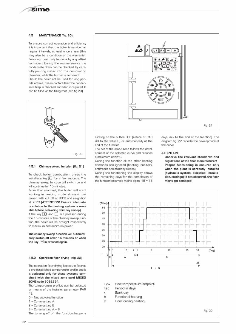
4.5 MAINTENANCE (fig. 20)
To ensure correct operation and efficiency it is important that the boiler is serviced at regular intervals, at least once a year (this may also be a condition of the warranty). Servicing must only be done by a qualified technician. During the routine service the condensate drain can be checked, by care-fully pouring water into the combustion chamber, while the burner is removed. Should the boiler not be used for long peri-ods of time, it is important that the conden-sate trap is checked and filled if required. It can be filled via the filling vent (see fig 20).
4.5.1 Chimney sweep function (fig. 21)
To check boiler combustion, press the installer’s key for a few seconds. The chimney sweep function will switch on and will continue for 15 minutes.From that moment, the boiler will start working in heating mode at maximum power, with cut off at 80°C and re-ignition at 70°C (ATTENTION! Ensure adequate circulation to the heating system is avail-able before activating chimney sweep).If the key and are pressed during the 15 minutes of the chimney sweep func-tion, the boiler will be brought respectively to maximum and minimum power.
The chimney sweep function will automati-cally switch off after 15 minutes or when the key is pressed again.
4.5.2 Operation floor drying (fig. 22)
The operation floor drying keeps the floor at a pre-established temperature profile and it is activated only for those systems com-bined with the mixed zone card MIXED ZONE code 8092234. The temperature profiles can be selected by means of the installer parameter PAR 43: 0 = Not activated function1 = Curve setting A2 = Curve setting B3 = Curve setting A + BThe turning off of the function happens
clicking on the button OFF (return of PAR 43 to the value 0) or automatically at the end of the function. The set of the mixed zone follows the devel-opment of the selected curve and reaches a maximum of 55°C. During the function all the other heating demands are ignored (heating, sanitary, antifreeze and chimney sweep). During the functioning the display shows the remaining days for the completion of the function (example mains digits -15 = 15
days lack to the end of the function). The diagram fig. 22 reports the development of the curve.
ATTENTION:- Observe the relevant standards and
regulations of the floor manufacturer!- Proper functioning is ensured only
when the plant is correctly installed (hydraulic system, electrical installa-tion, settings)! If not observed, the floor might get damaged!
Fig. 20
Fig. 21
50
45
40
35
30
205 10 15 18 [Tag]0
25
55
A B
1 15 7
X
A + B
1 25
[TVw]
Fig. 22
TVw Flow temperature setpointTag Period in daysx Start dayA Functional heatingB Floor curing heating

33
4.6 FUNCTIONING ERRORS
When there is a functioning error, an alarm appears on the display and the blue lumi-nous bar becomes red.Descriptions of the errors with relative alarms and solutions are given below:
– LOW WATER PRESSURE ERROR ALARM 02 (fig. 23/1)
If the pressure detected by the trans-ducer is lower than 0.5 bar, the gen-erator stops and the display shows the alarm ALL 02. Using the external filling device, fill the system until the pressure indicated by the transducer is between 1 and 1.5 bars.
If the refilling procedure has to be repeated several times, it is advisable to check that the soundness of the heating circuit is intact (check that there are no leaks).
– HIGH WATER PRESSURE ERROR ALARM 03 (fig. 23/2)
If the pressure detected by the trans-ducer is more than 4.8 bar, the gen-erator stops and the display shows error ALL 03.
– HEATING FLOW SENSOR ERROR ALARM 05 (fig. 23/4)
If the heating flow sensor (SM) is open or short circuited, the generator will not function and the display will show the alarm ALL 05.
– LOCKOUT ALARM 06 (fig. 23/5) If a flame has not been detected after
a complete ignition sequence, or for any other reason the card cannot “see” the flame, the generator will stop and the display will show the alarm ALL 06.
Press the key of the controls (2) to start up the generator again.
Fig. 23/5
2
Fig. 23/1
Fig. 23/2
Fig. 23/4

34
– SAFETY/LIMIT THERMOSTAT ERROR ALARM 07 (fig. 23/6)
If either the 95 degree stat or the heat exchanger safety stat opens, the burner will turn off and ALL 07 will be displayed.
Press the key of the controls (2) to start up the boiler again.
– PARASITE FLAME ERROR ALARM 08 (fig. 23/7)
If the flame control section recognises the presence of a flame in phases when one should not be present, it means there is a breakdown in the flame detec-tion circuit; the generator will stop and the display will show error ALL 08.
– WATER CIRCULATION ERROR ALARM 09 (fig. 23/8)
1. Water circulation has not been detect-ed in the primary (generator) circuit. If this error is detected the generator will make two further attempts. If the circu-lation is not detected the it will stop and indicate ALL 09.
Note: circulation is detected by a small rise in the system pressure when the pump is energised. In large systems this may not be detected, and can be disa-bled by alteration of PAR 4.
2. The flow temperature sensor has detected a rise in excess of 5 degrees per second.
– AUXILIARY SENSOR ALARM 10
(fig. 23/9) When the antifreeze siphon sensor (SA)
is open or short circuited, the display will show anomaly ALL 10.
– ACTIVATION OF THE “ALL 13” EXHAUST TEMPERATURE SENSOR (fig. 23/10)
The activation of this probe causes the boiler to stop and error message ALL 13 to display.
Press the key of the controls (2) to start up the boiler again.
– “ALL 14” EXHAUST TEMPERATURE SENSOR ERROR (fig. 23/11)
If the exhaust temperature sensor is open or short-circuited, the boiler stops and error message ALL 14 displays.
Fig. 23/7
Fig. 23/6
2
Fig. 23/9
2
Fig. 23/10
Fig. 23/11
2
Fig. 23/8

35
– “ALL 15” FAN ERROR (fig. 23/12) The fan speed does not fall within the
rated speed range. If the error conditions persists for two
minutes, the generator activates a forced stop for thirty minutes.
A new start attempt is repeated after the expiry of this interval of time.
– EXTERNAL PROBE ERROR “ FLASHING” (fig. 23/13)
When the external probe (SE) is short-circuited, the display the symbol flashes
. During such error the boiler continues
normal functioning.
– SAFETY THERMOSTAT INTERVEN-TION FIRST MIXED ZONE “ALL 20” (fig. 23/14)
When it results that the MIXED ZONE board is connected to the boiler the safe-ty thermostat intervention switches the mixed zone plant pump, the mix zone valve closes and on the display the anom-aly ALL 20.
During this anomaly the generator con-tinues to function normally.
– DELIVERY PROBE BREAKDOWN ANOMALY FIRST MIXED ZONE “ALL 21” (fig. 23/15)
When it results that the MIXED ZONE board is connected to the boiler and the delivery probe is open or short circuited on the display the anomaly ALL 21 appears.
During this anomaly, the boiler continues to function normally.
– SAFETY THERMOSTAT INTERVENTION SECOND MIXED ZONE “ALL 22” (fig. 23/16)
When it results that the MIXED ZONE board is connected to the boiler
The intervention of the safety thermostat switches the mixed zone plant pump, the mix zone valve closes and on the display the anomaly ALL 22. During this anomaly the boiler continues to function normally.
– DELIVERY PROBE BREAKDOWN ANOMALY SECOND MIXED ZONE “ALL 23” (fig. 23/17)
When it results that the MIXED ZONE board is connected to the boiler and the delivery probe is open or short circuited on the display the anomaly ALL 23 appears. During this anomaly the boiler continues to function normally.
– SOLAR COLLECTOR SENSOR ANOMA-LY (S1) “ALL 24” (fig. 23/18)
When the solar probe is open or short circuited, on the display the anomaly ALL 24 appears. During this anomaly the boiler continues to function normally but loses the solar function that is no longer available.
– SOLAR PROBE ANOMALY STORAGE TANK (S2) “ALL 25” (fig. 23/19)
When the solar probe is open or short circuited, on the display the anomaly ALL 25 appears. During this anomaly the boiler continues to function normally but loses the solar function that is no longer available.
– AUXILIARY SENSOR ANOMALY (S3) “ALL 26” (fig. 23/20)
When the solar probe is open or short circuited, on the display the anomaly ALL 26 appears. During this anomaly the boiler continues to function normally but loses the solar function that is no longer available.
– ANOMALY SOLAR APPLICATION COM-PATIBILITY “ALL 27” (fig. 23/21)
When the hydraulic configuration is not consistent with the selection solar appli-cation, on the display the anomaly ALL 27 appears. During this anomaly the boil-er continues to function normally but for the board is active in the solar anomaly, the function is only available antifreeze collector.
– COMPATIBILITY INPUT (S3) ANOMALY ONLY FOR SYSTEM 7 “ALL 28” (fig. 23/22)
When a probe is connected instead of a clean contact on entry S3 the board on display shows the anomaly ALL 28. During this anomaly the boiler continues to function normally but for the board is active in the solar anomaly, the function is only available antifreeze collector.
– ANOMALY NUMBERS REL ATED BOARD “ALL 29” (fig. 23/23)
When one of the board MIXED ZONE/INSOL failure or does not communicate, the display shows anomaly ALL 29. The boiler functional excluding the function MIXED ZONE/INSOL.
Fig. 23/12
Fig. 23/13
Fig. 23/14
Fig. 23/15
Fig. 23/16
Fig. 23/17
Fig. 23/18
Fig. 23/19
Fig. 23/20
Fig. 23/21
Fig. 23/22
Fig. 23/23

36
– HEATING RETURN SENSOR ERROR “ALL 30” (fig. 23/24)
When the heating return sensor (SR) is open or short-circuited, the display shows anomaly ALL 30. During such anomaly the generator continues normal functioning.
– CASCADE DELIVERY SENSOR ERROR “ALL 31” (fig. 23/25)
When the cascade delivery sensor (SMC) is open or shorted, ALL 31 will be dis-played.
– THREE-ZONE SYSTEM CONFIGURA-TION ANOMALY “ALL 32” (fig. 23/26)
When the boards connected to the RS-485 are not enough and/or at least one of them it is not mixing zone board, the boiler stops and anomaly ALL 32 is displayed. The boiler restarts when the boiler three-zone system configuration is activated
– RS-485 BOARD COMMUNICATION ANOMALY IN MODBUS MODE “ALL 33” (fig. 23/27)
When PAR 16 is different from “- -”and there is no communication between the boiler board and the RS-485 board in MODBUS mode for at least four minutes, the boiler stops and anomaly ALL 33 is displayed.
The boiler restarts when communication is restored or when PAR 16 = “- -” is set.
– RS-485 BOARD COMMUNICATION
ANOMALY IN CASCADE MODE “ALL 34” (fig. 23/28)
When PAR 15 is different from “- -” and there is no communication between the boiler board and the RS-485 board in CASCADE mode, the boiler stops and anomaly ALL 34 is displayed.
The boiler restarts when communication is restored or when PAR 15 = “- -” is set.
– RS-485 AND RS-485 COMMUNICA-TION ANOMALY “ALL 35” (fig. 23/29)
When PAR 15 is different from “- -” and there is no communication between the two RS-485 boards, the boiler stops and anomaly ALL 35 is displayed. The boiler restarts when communication is restored or when PAR 15 = “- -” is set.
CAUTION: In the event of sequence/cas-cade connection, error codes 70 and 71 will appear on the CR 73 remote control display:- ALARM 70 When an anomaly affects cascade
operation (cascade delivery sensor ALL 31), CR 73 remote control display will show alarm 70. Verify the anomaly in the cascade.
- ALARM 71 When an anomaly occurs in one of the
modules and the others keep operat-ing to the extent permitted, the CR 73 remote control display will show alarm 71. Verify the anomaly in the cascade.
Fig. 23/29
Fig. 23/24
Fig. 23/25
Fig. 23/27
Fig. 23/28
Fig. 23/26

37
Service RecordIt is recommended that your heating system is serviced regularly and that the appropriate Service Interval Record is completed. This is also a condition of any extended warranty offered.
Service ProviderBefore completing the appropriate Service Record below, please ensure you have carried out the service as described in the manufacturer’s instructions.
Always use the manufacturer’s specified spare part when replacing controls.
Date:
Engineer Name:
Company Name:
Telephone No.
Gas Safe Register No.
Comments CO: CO2: RATIO:
Signature:
Date:
Engineer Name:
Company Name:
Telephone No.
Gas Safe Register No.
Comments CO: CO2: RATIO:
Signature:
Date:
Engineer Name:
Company Name:
Telephone No.
Gas Safe Register No.
Comments CO: CO2: RATIO:
Signature:
Date:
Engineer Name:
Company Name:
Telephone No.
Gas Safe Register No.
Comments CO: CO2: RATIO:
Signature:
Date:
Engineer Name:
Company Name:
Telephone No.
Gas Safe Register No.
Comments CO: CO2: RATIO:
Signature:
Date:
Engineer Name:
Company Name:
Telephone No.
Operative ID No.
Comments CO: CO2: RATIO:
Signature:
Date:
Engineer Name:
Company Name:
Telephone No.
Gas Safe Register No.
Comments CO: CO2: RATIO:
Signature:
Date:
Engineer Name:
Company Name:
Telephone No.
Gas Safe Register No.
Comments CO: CO2: RATIO:
Signature:
Date:
Engineer Name:
Company Name:
Telephone No.
Gas Safe Register No.
Comments CO: CO2: RATIO:
Signature:
Date:
Engineer Name:
Company Name:
Telephone No.
Gas Safe Register No.
Comments CO: CO2: RATIO:
Signature:
Service 1 Service 2
Service 3 Service 4
Service 5 Service 6
Service 7 Service 8
Service 9 Service 10
38
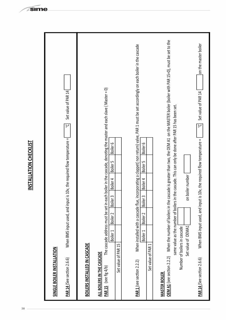
INST
ALLA
TION
CHE
CKLIS
T
SING
LE B
OILE
R IN
STAL
LATI
ON
PAR
14 (S
ee se
c�on
2.6.
6)W
hen
BMS i
nput
use
d, an
d in
put i
s 10v
, the
requ
ired
flow
tem
pera
ture
=°C
Set v
alue o
f PAR
14
BOILE
RS IN
STAL
LED
IN C
ASCA
DE
ALL B
OILE
RS IN
THE C
ASCA
DEPA
R 15
(se
e fig 4
/b)
The c
asca
de ad
dres
s mus
t be s
et in
each
boi
ler in
the c
asca
de, d
eno�
ng th
e mas
ter a
nd ea
ch sl
ave (
Mas
ter =
0)Bo
iler 1
Boile
r 2Bo
iler 3
Bo
iler 4
Boile
r 5
Boile
r 6Se
t valu
e of P
AR 15
PAR
1 (se
e sec
�on
2.2.
2) W
hen
insta
lled
with
a ca
scad
e flue
, inco
rpor
a�ng
a cla
ppet
( non
retu
rn) v
alve,
PAR
1 m
ust b
e set
acco
rdin
gly o
n ea
ch b
oiler
in th
e cas
cade
Boile
r 1Bo
iler 2
Boile
r 3
Boile
r 4Bo
iler 5
Bo
iler 6
Set v
alue o
f PAR
1
MAS
TER
BOILE
R OE
M A
1 (se
e sec
�on
2.2.
2) W
hen
the n
umbe
r of b
oiler
s in
the c
asca
de is
grea
ter t
han
two,
the O
EM A
1 on
the M
ASTE
R bo
iler (
boile
r with
PAR
15=0
), m
ust b
e set
to th
e sa
me v
alue a
s the
num
ber o
f boi
lers i
n th
e cas
cade
. Thi
s can
onl
y be d
one a
�er P
AR 15
has
bee
n se
t.Nu
mbe
r of b
oiler
s in
casc
ade
Set v
alue o
f OE
MA1
on
boile
r num
ber
PAR
14 (S
ee se
c�on
2.6.
6)W
hen
BMS i
nput
use
d, an
d in
put i
s 10v
, the
requ
ired
flow
tem
pera
ture
= °C
Set v
alue o
f PAR
14
on th
e mas
ter b
oiler
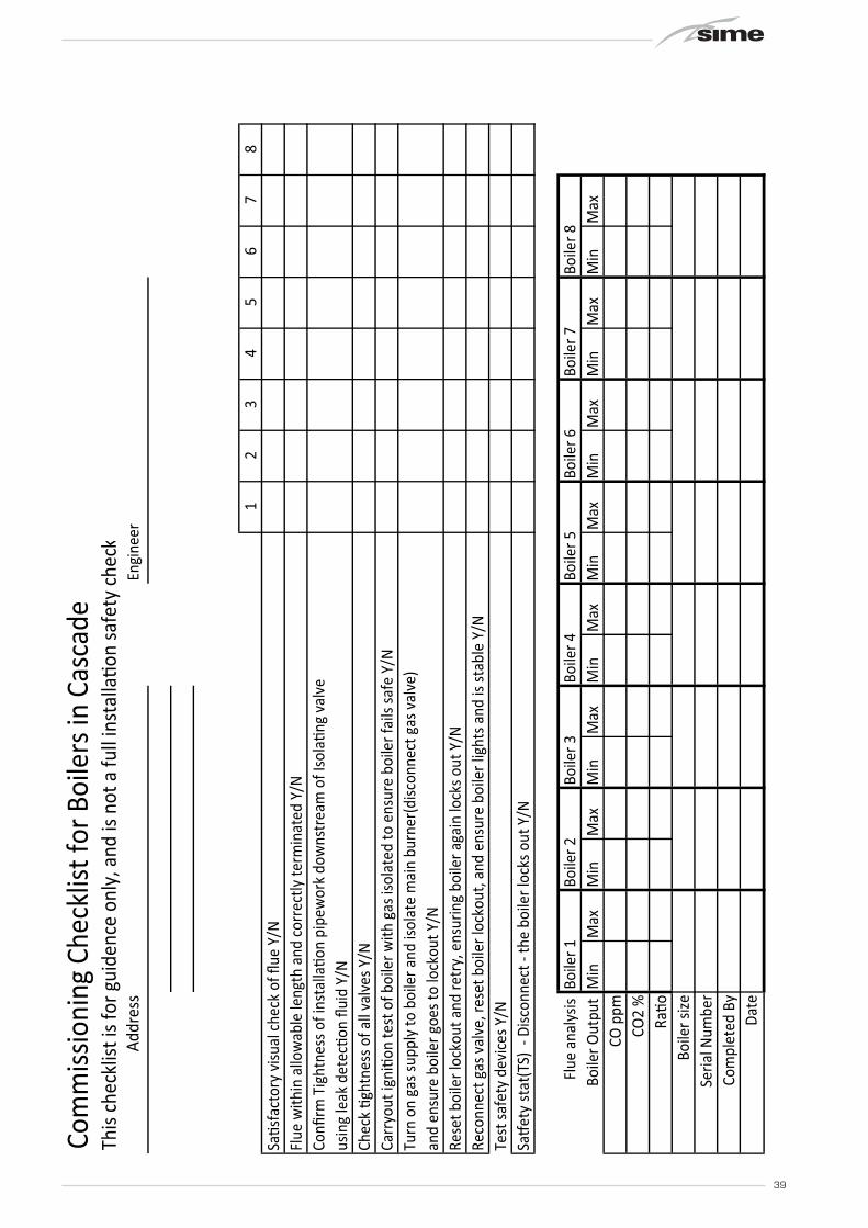
39
Com
miss
ioni
ng C
heck
list f
or B
oile
rs in
Cas
cade
This
chec
klist
is fo
r gui
denc
e on
ly, a
nd is
not
a fu
ll in
stal
la�o
n sa
fety
che
c kAd
dres
sEn
gine
er
12
34
56
78
Sa�s
fact
ory
visu
al c
heck
of fl
ue Y
/NFl
ue w
ithin
allo
wab
le le
ngth
and
cor
rect
ly te
rmin
ated
Y/N
Confi
rm T
ight
ness
of i
nsta
lla�o
n pi
pew
ork
dow
nstr
eam
of I
sola
�ng
valv
eus
ing
leak
det
ec�o
n flu
id Y
/NCh
eck
�ght
ness
of a
ll va
lves
Y/N
Carr
yout
igni
�on
test
of b
oile
r with
gas
isol
ated
to e
nsur
e bo
iler f
ails
safe
Y/N
Turn
on
gas s
uppl
y to
boi
ler a
nd is
olat
e m
ain
burn
er(d
iscon
nect
gas
val
ve)
and
ensu
re b
oile
r goe
s to
lock
out Y
/NRe
set b
oile
r loc
kout
and
retr
y, e
nsur
ing
boile
r aga
in lo
cks o
ut Y
/NRe
conn
ect g
as v
alve
, res
et b
oile
r loc
kout
, and
ens
ure
boile
r lig
hts a
nd is
stab
le Y
/NTe
st sa
fety
dev
ices
Y/N
Sa�e
ty st
at(T
S) -
Disc
onne
ct -
the
boile
r loc
ks o
ut Y
/N
Flue
ana
lysis
Boi
ler 1
Boile
r 2Bo
iler 3
Boile
r 4Bo
iler 5
Boile
r 6Bo
iler 7
Boile
r 8Bo
iler O
utpu
t M
inM
axM
inM
axM
inM
axM
inM
axM
inM
axM
inM
axM
inM
axM
inM
axCO
ppm
CO2
%Ra
�oBo
iler s
ize
Seria
l Num
ber
Com
plet
ed B
yDa
te

40
If an electrical fault occurs on the appliance the preliminary electrical system checks must be carried out first. When any service or replacement of elec-trical components which has required the breaking and re-making of electrical con-nections has taken place, the following tests must be repeated:– earth continuity;– short circuit;– polarity;– resistance to earth.
5.1 EARTH CONTINUITY CHECK
Appliances must be electrically disconnect-ed, meter set on ø (ohm) x 1 scale and adjust zero if necessary. Tests leads from any appliance earth point (e.g. inside control box) see wiring diagrams (section 7) to earth pin on plug. Resistance should be less than 1 ø (ohm). If the resistance is greater than 1 ø (ohm) check all earth wires for continuity and all contacts are clean and tight. If the resist-ance to earth is still greater than 1 ø (ohm) then this should be investigated futher.
5.2 SHORT CIRCUIT CHECK
Switches turned FULL ON - meter set on ø (ohms) x 1 scale. Test leads from L to N on appliance terminal block, if meter reads 0
then there is a short circuit.Meter set on ø (ohm) x 100 scale. Repeat it with leads from L to E. If meter reads less than infinity (?) there is a fault.
NOTE: Should it be found that the fuse has failed but no fault is indicated, a detailed continuity check (i.e. by disconnecting and checking each component) is required to trace the faulty component. It is pos-sible that a fault could occur as a result of local burning/arcing but no fault could be found under test. However, a detailed visual inspection should reveal evidence of burning around the fault.
5.3 POLARITY CHECK
Appliance reconnected to mains supply and meter set on 300 V ac scale. Test at appli-ance terminal block.– Test leads from L to N meter reads
approx.: 240 V ac.– Test leads from L to E “” meter reads
approx. 240 V ac.– Test leads from N to E “” meter reads
from 0 to 15 V ac.
5.4 RESISTANCE TO EARTH CHECK
Appliance must be disconnected from main supply and meter on ø (ohm) x 100 scale.
All switches including thermostat on test leads from L to E - if meter reads other than infinity (?) there is a fault which should be isolated. A detailed continuity check is required to trace the faulty component.
IMPORTANT: These series of checks are the first elec-trical checks to be carried out during a fault finding procedure. On completion of the service/fault finding task which has required the breaking and remaking of electrical connections then the checks 5.1 Earth continuity, 5.3 Polarity and 5.4 Resistance to earth must be repeated.
5 FAULT FINDING

41
INDUSTRY GUIDANCE FOR INSTALLERS ON CONDENSATE
DRAINAGE PIPE INSTALLATION
This guidance is endorsed by HHIC members.
1. BACKGROUND
During recent winters the UK has experienced prolonged spells of extremely cold weather - down to minus 20oC and below in many areas. This resulted in a significant increase in the number of calls to boiler manufacturers and heating engineers from householders with condensing (high efficiency) boilers where the condensate drainage pipe had frozen andbecome blocked with ice, causing the boiler to shut down. In the vast majority of cases such problems occur where the condensate drainage pipe is located externally to the building for some part of its length.
British Standards, Building Regulations etc. currently allow condensate drainage pipes to berun either internally or externally, or a combination of these. These documents give guidance on how to install the pipes in order to reduce the possibility of freezing. However this guidance may not be sufficient to prevent freezing in extreme conditions - with widespread and prolonged very low temperatures.
In view of the possibility that UK weather patterns will show more “extremes” in future due to the effects of global climate change, the following guidance updates previous recommendations on condensate drainage pipe installation. All other technical requirements for condensate drain installation given in British Standard BS 6798:2009, or in boiler manufacturers’ installation instructions should still be followed.
2. REVISED GUIDANCE ON CONDENSATE DRAINAGE PIPE INSTALLATION
Where a new or replacement boiler is being installed, access to an internal “gravity discharge” termination should be one of the main factors considered when determining potential boiler locations, so that the condensate drainage pipe can be terminated as recommended below. On an existing installation, the guidance below should also be followed if work is carried out to “upgrade” the condensate drain age system to reduce the risk of freezing in extreme conditions.
Internal condensate drainage pipework must be a minimum of 19mm ID (typically 22mm OD) plastic pipe and this should “fall” at least 45 mm per metre away from the boiler, taking the shortest practicable route to the termination point.
In order to minimise the risk of freezing during prolonged very cold spells, one of the following methods of terminating condensate drainage pipe should be adopted -
42
2.1 INTERNAL TERMINATION:
Wherever possible, the condensate drainage pipe should be terminated at a suitable internal foul water discharge point such as (a) an internal soil and vent stack or (b) an internal kitchen or bathroom waste pipe, washing machine waste pipe etc. A suitable permanent connection to the foul waste pipe should be used. Figures 1, 2(a), 2(b) show appropriate connection methods.
The possibility of waste pipes freezing downstream of the connection point should beconsidered when determining a suitable connection point - e.g. a slightly longer pipe run to an internal soil stack may be preferable to a shorter run connecting into a kitchen waste pipe discharging directly through the wall to an external drain.
Where “gravity discharge” to an internal termination is not physically possible (e.g. the discharge point is above the appliance location, or access is obstructed by a doorway), or where very long internal pipe runs would be required to reach a suitable discharge point, the following measures may be adopted -
2.2 USE OF A CONDENSATE PUMP (TO AN INTERNAL TERMINATION):
Condensate can be removed using a proprietary condensate pump, of a specification recommended by the boiler or pump manufacturer.
The pump outlet should discharge to a suitable internal foul water discharge point, such as (a) an internal soil and vent stack or (b) an internal kitchen or bathroom waste pipe, washing machine waste pipe etc. Figure 3 shows a typical connection method.
A suitable permanent connection to the foul waste pipe should be used and the manufacturer’s detailed installation instructions for the pump should be followed.
2.3 EXTERNAL TERMINATION:
The use of an externally-run condensate drainage pipe, terminating at a suitable foul water discharge point or purpose-designed soakaway, may be also be considered; however if this termination method is chosen then the following measures should be adopted -
The pipe should be run internally as far as possible before going externally and the pipe diameter should be increased to a minimum of 30mm ID (typically 32mm OD) before it passes through the wall.
The external run should be kept as short as possible, taking the most direct and “most vertical” route possible to the discharge point, with no horizontal sections in which condensate might collect.
The external pipe should be insulated using suitable waterproof and weatherproof insulation (“Class O” pipe insulation is suitable for this purpose) .
43
The use of fittings, elbows etc should be kept to a minimum and any internal “burrs” on cut pipework should be removed so that the internal pipe section is as smooth as possible.
The customer/householder should be advised that even with the above measures this type of installation could freeze, and that if this were to occur then boiler shutdown could result, requiring remedial action - possibly involving a chargeable engineer call-out.
Where there are likely to be extremes of temperature or wind-chill, the use of a proprietary trace-heating system for external condensate drainage pipework, incorporating an external frost thermostat, should therefore be considered. If such a system is used then the installation instructions of the trace heating manufacturer and any specific recommendations regarding pipe diameter, insulation, etc. should be followed. All other relevant guidance on condensate drainage pipe installation should also be followed.
Other cold weather protection methods approved or endorsed by boiler manufacturers and/or service organisations may be adopted if these are considered suitable by the parties involved.
If an external soil/vent stack is used as the external termination then the connection method shown in Figure 4 should be used, together with the measures on insulation etc. as described above and shown in the diagram.
When a rain water downpipe is used as the termination (NB only permissible if this downpipe passes to a combined foul and rainwater drainage system) an air break must be installed between the condensate drainage pipe and the downpipe to avoid reverse flow of rainwater into the boiler should the downpipe itself become flooded or frozen. Figure 5 shows a suitable connection method.
Where the condensate drainage pipe is terminated over an open foul drain or gully, the pipe should terminate below the grating level, but above water level, in order to minimise “wind chill” at the open end. Pipe drainage will be improved if the end is cut at 45o as opposed to a straight cut. The use of a drain cover (such as those used to prevent blockage by leaves) may offer further protection from wind chill. Figure 6 shows a suitable connection method.
Where the condensate drain pipe terminates in a purpose-designed soakaway (see BS 6798:2009 or boiler installation manual for soakaway design requirements) any above-ground section of condensate drainage pipe should be run and insulated as described above. Figure 7 shows a suitable connection method.
3. UNHEATED INTERNAL AREAS:
Internal condensate drainage pipes run in unheated areas such as lofts, basements and garages should be treated as external pipe.

44
NOTES
The Benchmark Commissioning Checklist (located at the back of the boiler installation manual) should be completed as required to record details of the condensate drainage pipe installation.
Where an external condensate drainage pipe is installed, the customer should be made aware of the risks and consequences of its freezing and offered the option to fit trace heating (or other measures approved by the boiler manufacturer or service organisation).
Separate guidance has been published for householders on remedial actions which can be taken if a condensate drainage pipe freezes. This may result in requests for alteration to condensate drainage pipework, in which case the guidance above should be followed.
In some instances (e.g. where an elderly person’s heating needs to be reinstated as an emergency measure) condensate drainage pipes may have been cut in order to bypass any blockage and allow re-ignition of the boiler, with condensate being collected in a suitable container as a temporary solution.
While not unsafe, this is not recommended practice and if such action has been taken then the condensate drainage pipe must be reinstated as soon as possible, using the above guidance to reduce risk of freezing in future.

45
Figure 1 – Connection of condensate drainage pipe to internal soil and vent stack
Key1 Boiler2 Visible air break3 75 mm trap4 Visible air break and trap not required if there is a trap with a minimum condensate
seal of 75 mm incorporated into the boiler5 Soil and vent stack6 Invert7 450 mm minimum up to three storeys8 Minimum internal diameter 19 mm

46
Figure 2(a) – Connection of a condensate drainage pipe downstream of a sink, basin, bath or shower waste trap
Key1 Boiler2 Visible air break3 75 mm trap4 Visible air break and trap not required if there is a trap with a minimum condensate
seal of 75 mm incorporated into the boiler. In this case the 100 mm is measured to the trap in the boiler.
5 Sink, basin, bath or shower6 Open end of condensate drainage pipe direct into gully 25 mm min below grating but
above water level; end cut at 45 °7 Sink lip8 Minimum internal diameter 19 mm9 Pipe size transition10 Minimum internal diameter 30 mm11 Water/weather proof insulation

47
Figure 2(b) – Connection of a condensate drainage pipe upstream of a sink, basin, bath or shower waste trap
Key1 Boiler2 Visible air break at plug-hole3 75 mm sink, basin, bath or shower waste trap4 Sink, basin, bath or shower with integral overflow5 Open end of condensate drainage pipe direct into gully 25 mm min below grating but
above water level; end cut at 45 °6 Minimum internal diameter 19 mm7 Pipe size transition8 Minimum internal diameter 30 mm9 Water/weather proof insulation

48
Figure 3 – Connection of a condensate pump - typical method (NB manufacturer’s detailed instructions should be followed).
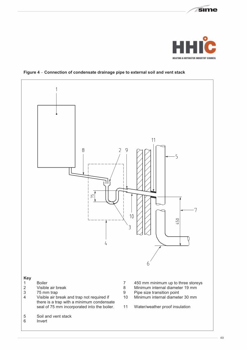
49
Figure 4 – Connection of condensate drainage pipe to external soil and vent stack
Key1 Boiler 7 450 mm minimum up to three storeys2 Visible air break 8 Minimum internal diameter 19 mm3 75 mm trap 9 Pipe size transition point4 Visible air break and trap not required if
there is a trap with a minimum condensate seal of 75 mm incorporated into the boiler.
10 Minimum internal diameter 30 mm
11 Water/weather proof insulation
5 Soil and vent stack6 Invert
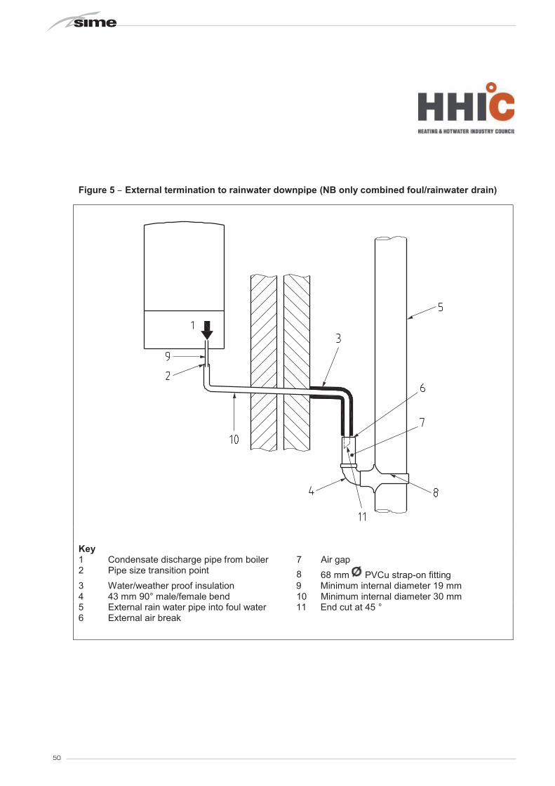
50
Figure 5 – External termination to rainwater downpipe (NB only combined foul/rainwater drain)
Key1 Condensate discharge pipe from boiler 7 Air gap2 Pipe size transition point 8 68 mm PVCu strap-on fitting3 Water/weather proof insulation 9 Minimum internal diameter 19 mm4 43 mm 90° male/female bend 10 Minimum internal diameter 30 mm5 External rain water pipe into foul water 11 End cut at 45 °6 External air break

51
Figure 6 – External drain, gully or rainwater hopper
Key
1 Boiler2 Visible air break3 38 mm minimum trap4 Visible air break and trap not required if there is a trap with a minimum condensate
seal of 38 mm incorporated into the boiler5 External length of pipe 3 m maximum6 Open end of condensate drainage pipe direct into gully 25 mm min below grating but
above water level; end cut at 45 °7 Minimum internal diameter 19 mm8 Pipe size transition point9 Minimum internal diameter 30 mm10 Water/weather proof insulation

52
Figure 7 – Example of a purpose-made soakaway
Key
1 Condensate discharge pipe from boiler2 Ground (this section of the condensate drainage pipe may be run either above or
below ground level); End cut at 45 °3 Diameter 100 mm minimum plastic tube4 Bottom of tube sealed5 Limestone chippings6 Two rows of three 12 mm holes at 25 mm centres, 50 mm from bottom of tube and
facing away from house7 Hole depth 400 mm minimum by 300 mm diameter8 Minimum internal diameter 19 mm9 Pipe size transition point10 Minimum internal diameter 30 mm11 Water/weather proof insulation

53

54


@