MUNICIPAL INFRASTRUCTURE STANDARDS · MUNICIPAL INFRASTRUCTURE STANDARDS PART 10 FENCES, GUARDRAILS...
17
MUNICIPAL INFRASTRUCTURE STANDARDS PART 10 FENCES, GUARDRAILS AND BARRIERS Publication Number: MIS 10 Edition 0 Revision 0 Date of Effect: Supersedes: Design Standard for Urban Infrastructure Works Section 11 Edition 1 Revision 0 September 2002 Endorsed By: Approved By:
Transcript of MUNICIPAL INFRASTRUCTURE STANDARDS · MUNICIPAL INFRASTRUCTURE STANDARDS PART 10 FENCES, GUARDRAILS...

MUNICIPAL INFRASTRUCTURE
STANDARDS PART 10 FENCES, GUARDRAILS AND
BARRIERS
Publication Number: MIS 10 Edition 0 Revision 0 Date of Effect:
Supersedes:Design Standard for Urban Infrastructure Works Section 11 Edition 1 Revision 0 September 2002
Endorsed By:
Approved By:

ACT Government
Page 2 of 17
Edition 0 Revision 0 MIS 10 Fences, guardrails and barriers Municipal Infrastructure Standard
Document Information
Document Key Information
Document title MIS 10 Fences, guardrails and barriers
Next review date
Key words
AUS-SPEC Base Document
N/A
Revision Register
Ed/Rev Number
Clause Number
Description of Revision Authorised By Date
Draft /1 Targeted Meeting issue 19 Jun 14
Draft /2 Working Group issue 6 Aug 14
Draft /3 Revised with comments 11 Aug 14
Draft /4 Added working width details and Working Group comments
10 Sep 14
Draft /5 Revised with additional comments
1 Oct 14
Draft /6 Revised with PACS comments 9 Oct 14
Draft /7 Revised with comments 10 Oct 14
Draft /8 Revised with Working Group comments
21 Nov 14
Draft /9 Revised with PACS comments 8 Dec 14
0/0 Issued for comment 23 Nov 15

ACT Government
Page 3 of 17
Edition 0 Revision 0 MIS 10 Fences, guardrails and barriers Municipal Infrastructure Standard
1 PREFACE
The Austroads series of Guides for provision and management of road and transport infrastructure provides a level of consistency across all jurisdictions in Australia and New Zealand. All road authorities have agreed to adopt the Austroads Guides as the primary technical reference, together with the relevant Australian and New Zealand Standards.
The Australian Capital Territory has adopted the Austroads Guides, and has issued a revised series of documents to reflect this development in standards and specifications for practice in the ACT. The ACT Government accepts the principles and general guidance in the Austroads Guide to Road Design. This Municipal Infrastructure Standard is issued to clarify any exceptions or additional requirements for implementation in the ACT, and to identify relevant complementary documents.
This present document is part of the ACT Municipal Infrastructure Standard (MIS) series spanning the broad scope of municipal infrastructure development and management in the ACT. Whilst based on the earlier Urban Services Design Standards for Urban Infrastructure Works, this document has been significantly expanded to incorporate new technologies and to bring it into line with Australian best practice. This revised series uses AUS-SPEC (October 2013) format wherever practical.
For the purposes of this series of standards, municipal infrastructure pertains to road works (except arterial and higher order roads), stormwater drainage and landscaping required to service residential, commercial and industrial estates for both greenfield and brownfield/urban in-fill developments. They are works to be owned and maintained by Territory and Municipal Services (TAMS) and to be constructed either by a developer and gifted to the ACT Government or constructed as part of the ACT Government Capital Works program. In all developments, if these Design Standards cannot be appropriately applied the proposed innovation should be discussed with and approved by TAMS.
Municipal Infrastructure Standards
MIS 01 Street planning and design
MIS 02 Earthworks and site grading
MIS 03 Pavement design
MIS 04 Subsurface drainage
MIS 05 Active Travel
MIS 06 Verges
MIS 07 Driveways
MIS 08 Stormwater
MIS 09 Bridges and related structures
MIS 10 Guardrails, fences and barriers
MIS 11 Off-street parking
MIS 12 Guide signs
MIS 13 Traffic Control Devices
MIS 14 Public lighting
MIS 15 Urban edge Management Zone
MIS 16 Urban open space
MIS 17 Shopping centres and other public urban spaces
MIS 19 Sportsground design
MIS 20 Street and park furniture and barbeques
MIS 21 Playgrounds and playground equipment

ACT Government
Page 4 of 17
Edition 0 Revision 0 MIS 10 Fences, guardrails and barriers Municipal Infrastructure Standard
MIS 23 Public toilets
MIS 24 Soft landscape design
MIS 25 Plant species for urban landscape projects
MIS 26 Irrigation
MIS 27 Signage for shopping centres and other urban spaces
Attachment A Drawings
Trunk Road Infrastructure Standards
TRIS 01 Road planning
TRIS 02 Road design
TRIS 03 Traffic management
TRIS 04 Road safety
TRIS 05 Asset management
TRIS 06 Pavement design
TRIS 07 Bridges and related structures
TRIS 08 Road tunnels
TRIS 09 Project delivery
TRIS 10 Project evaluation

ACT Government
Page 5 of 17
Edition 0 Revision 0 MIS 10 Fences, guardrails and barriers Municipal Infrastructure Standard
CONTENTS
1 Preface ............................................................................................................................................ 3
2 Fences, guardrails and barriers ................................................................................................... 6
2.1 General .................................................................................................................................... 6
2.1.1 Responsibilities ................................................................................................................... 6
2.1.2 Cross references ................................................................................................................. 6
2.1.3 Referenced documents ....................................................................................................... 7
2.1.4 Standards ............................................................................................................................ 8
2.1.5 Interpretation ....................................................................................................................... 8
2.2 Pre-design planning ................................................................................................................ 9
2.2.1 Consultation ........................................................................................................................ 9
2.3 Design ................................................................................................................................... 10
2.3.1 Clear zone ......................................................................................................................... 10
2.3.2 Road Safety Barriers ......................................................................................................... 10
2.3.3 Vehicle Exclusion Barriers ................................................................................................ 11
2.3.4 Public Exclusion Barriers .................................................................................................. 14
2.3.5 Fences ............................................................................................................................... 14
2.3.6 Gates ................................................................................................................................. 15
2.4 Documentation ...................................................................................................................... 16
3 Appendix A – Level changes ...................................................................................................... 17
3.1 General .................................................................................................................................. 17
3.1.1 Level changes ................................................................................................................... 17
LIST OF FIGURES
Figure 10-1 Stopped gate opening figure ......................................................................................... 15

ACT Government
Page 6 of 17
Edition 0 Revision 0 MIS 10 Fences, guardrails and barriers Municipal Infrastructure Standard
2 FENCES, GUARDRAILS AND BARRIERS
2.1 GENERAL
2.1.1 RESPONSIBILITIES
2.1.1.1 Objective
General: Provide design and documentation for all classes of permanent safety barriers and fences in the public realm, including the following:
- Road Safety barriers
- Vehicle exclusion barriers
- Path barriers
- Public exclusion barriers
- Gates
Bridges: For barriers associated with bridges, including safety screens, refer to MIS 09.
Roadwork: For temporary barriers associated with roadwork, refer to MITS 01.
Objectives: Where fences, guardrails or barriers are required, provide the following:
- Convenient and safe access for maintenance functions.
- Selection of standardised systems that allow rapid replacement with readily available components.
- A durable system that minimises whole of life costs and exhibits high resistance to vandalism.
- An appropriate response to climate, geology and topography, existing built fabric, heritage and cultural context of the area.
- Consideration for Safety in design, operation and demolition.
2.1.1.2 Precedence
Where any document except legislation or the Territory Plan issued in conjunction with this Design Standard includes technical requirements that conflict with this Design Standard, the requirements of this Design Standard take precedence.
2.1.2 CROSS REFERENCES
2.1.2.1 Commonwealth Legislation
Australian Capital Territory Planning and Land Management Act 1988
Environment Protection and Biodiversity Conservation Act 1999
2.1.2.2 ACT Legislation
Environment Protection Act 2001
Heritage Act 2004
Planning and Development Act 2007
Planning and Development Regulation 2008
Public Roads Act 1902
Public Unleased Land Act 2013

ACT Government
Page 7 of 17
Edition 0 Revision 0 MIS 10 Fences, guardrails and barriers Municipal Infrastructure Standard
Road Transport (General) Act 1999
Road Transport (Safety and Traffic Management) Act 1999
Road Transport (Safety and Traffic Management) Regulation 2000
Territory Plan 2008 and related Codes
Work Health and Safety Act 2011
2.1.2.3 ACT Government Strategic Documents
ACT Pest Animals Management Strategy 2012 – 2022
Nature Conservation Strategy 2013 – 2013
2.1.2.4 Design Standards
Requirement: Conform to the following Design Standards:
MIS 01 Street planning and design
MIS 05 Active Travel
MIS 09 Bridges and related structures
MIS 16 Urban open space
Attachment B Design acceptance submissions
2.1.2.5 Specifications
The following specification is related to this standard:
MITS 01 Roadwork
2.1.2.6 TAMS Reference Documents
Reference document 4 Protection of public landscape assets
Reference document 6 Design Acceptance submissions
Reference document 7 Operational acceptance submissions
Reference document 8 WAE quality records
Reference document 9 Final acceptance submissions
Reference document 10 Landscape consolidation
2.1.3 REFERENCED DOCUMENTS
2.1.3.1 Standards
General: The following documents are incorporated into this Design Standard by reference:
AS/NZS 3845:1999 Road safety barrier systems
2.1.3.2 Standard Drawings
ASD-1001 Protective fences and barriers Sheet 1
ASD-1002 Protective fences and barriers Sheet 2
ASD-1003 Standard ranger gate
ASD-1004 Vehicle access gate (Heavy duty)
ACT Government
Page 8 of 17
Edition 0 Revision 0 MIS 10 Fences, guardrails and barriers Municipal Infrastructure Standard
2.1.3.3 Other Publications
National Construction Code
Roadside dining protection – a guideline for local authorities in South Australia, Transport SA, 13 November 2000 (available online at http://www.dhs.sa.gov.au/crash-barriers/).
Nature strip development application Form, TAMS Version 1.1.
Austroads
AGRD06-2009 Guide to road design – Roadside design, safety and barriers
AGRD06A-2009 Guide to road design – Pedestrian and cyclist paths
AGRD06B-2009 Guide to road design – Roadside environment
AGRS09-2008 Guide to road safety – Roadside hazard management
2.1.4 STANDARDS
2.1.4.1 General
Road Safety Barrier design: To AS 3845.
2.1.5 INTERPRETATION
2.1.5.1 Abbreviations
General: For the purposes of this Design Standard the following abbreviations apply:
NCC: National Construction Code
TAMS: Territory and Municipal Services, ACT Government, ACT Government and its successors.
2.1.5.2 Definitions
General: For the purpose of this Design Standard, the definitions of terms used to define the components of the road reserve are in conformance with AS 1348, Glossary of Austroads Terms and AGRD03. Definitions that pertain to this Design Standard are outlined below,
- Clear zone: The area adjacent to the traffic lane that should be kept free from features that would be potentially hazardous to errant vehicles.
- Frangible: Roadside furniture designed to collapse on impact. The severity of potential injuries to the occupants of an impacting vehicle is reduced, compared to those that could occur if the furniture was unyielding.
- Public exclusion barriers: A physical barrier sufficient to provide separation between pedestrian areas and the road. This barrier is not rigid enough to become a hazard if struck by vehicles and is also not a road safety barrier.
- Run-off zone:
- Road safety barriers: A physical barrier provided to separate roadside hazards or opposing traffic. These barriers are designed to resist penetration by an errant or out of control vehicle and as far as practicable, to stop or redirect colliding vehicles. Road safety barriers in use within the ACT fall into 3 categories:
- Rigid barriers: Concrete barriers.
- Semi-rigid barriers: Metal guardrails such as W-Beam and Thrie Beam.
- Flexible barriers: Wire rope barriers.

ACT Government
Page 9 of 17
Edition 0 Revision 0 MIS 10 Fences, guardrails and barriers Municipal Infrastructure Standard
- Vehicle exclusion barriers: A physical barrier sufficient to deter vehicles from accessing verge areas. This barrier is not rigid enough to become a hazard if struck be vehicles and is also not a road safety barrier.
- Working width (road safety barrier): The minimum width that is required to prevent an impacting design vehicle from colliding with an object behind a road safety barrier system. This includes both the dynamic deflection of the road safety barrier (if any) and the extra width to allow for the roll (vertical rotation) of an impacting vehicle. This ensures that the system width can be accommodated between the deformed road safety barrier and the hazard during impact and that the top of a high heavy vehicle will not impact a high hazard during impact.
2.2 PRE-DESIGN PLANNING
2.2.1 CONSULTATION
2.2.1.1 TAMS and other Authorities
Requirements: Consult with TAMS and other relevant Authorities during the preparation of design. In addition to the requirements of this Design Standard, identify the specific design requirements of these authorities. Consult with TAMS to determine where fencing and access is required (including locks on gates) for public open space areas.
Verge works in brownfield areas: Refer to the Nature strip development application Form.
2.2.1.2 Utilities services plans
Existing site conditions: Obtain service plans from all relevant utilities and other organisations whose services, trees, important ecological habitats or other assets exist within the area of the proposed development. Plot this information on the relevant drawings including the plan and cross-sectional views. As a minimum, designs should refer to ‘Dial-before-you-dig’ information that is readily available in most areas.
Responsibility: Confirm service plans accuracy with onsite inspection and also potholing if deemed necessary. Ensure that the working width is maintained between any proposed road safety barriers and existing above ground services.
Service authorities: Consult with relevant service authorities where underground services are located within or in close proximity to the clear zone. Provide consideration for safe access for maintenance functions.
2.2.1.3 Safety in Design
Requirement: Implement safety in design processes in accordance with the Work Health and Safety Act.
Design to mitigate hazards: Adopt a risk management process in accordance with AGRD06 Figure 4.1.
2.2.1.4 Proposed new services
Requirement: Detail any new services proposed or relocated as part of the proposed works.
ACT Government
Page 10 of 17
Edition 0 Revision 0 MIS 10 Fences, guardrails and barriers Municipal Infrastructure Standard
2.2.1.5 Hazard removal
Barrier or guardrail selection: Assess the whole of life cost for providing and maintaining barriers or guardrails against other hazard treatment options, including hazard removal. Options for hazard removal include the following:
- Extend culverts beyond the clear zone.
- Replace culvert inlets with plantation sumps.
- Remove or relocate hazards such as trees, poles, signs and other roadside furniture.
2.3 DESIGN
2.3.1 CLEAR ZONE
General: Any non-frangible obstacle within the clear zone could pose a hazard to an errant vehicle. Common hazards include electrical poles, trees with elements greater than 150 mm in diameter. The clear zone is a compromise between the recovery area for every errant vehicle, the cost of providing that area and the probability of an errant vehicle encountering a hazard.
Clear zone distances: Refer to AGRD06 Clause 4.2.
Requirement: The clear zone should be kept free of non-frangible hazards where economically and environmentally possible. Alternatively, hazards within the clear zone should be treated to make them safe or be shielded by an appropriate road safety barrier. Undertake a risk assessment for each situation where non-frangible hazards exist within a clear zone.
2.3.2 ROAD SAFETY BARRIERS
2.3.2.1 General
General: Road safety barriers are not commonly required in municipal streets due to the lower speed environment and fewer embankments. However, there may be specific situations where road safety barriers are warranted.
Design: To AS 3845 and AGRD06.
Objective: Provide road safety barriers where the following conditions apply:
- The consequences of impact with the unshielded hazard are greater than the consequence of impacting the barrier.
- There is a high likelihood that vehicles will leave the carriageway.
- There is a high level of consequence to the vehicle occupants, other road users or roadside features associated with vehicles leaving the carriageway.
Vehicle type: Select barriers with consideration for the type of vehicle likely to be involved.
2.3.2.2 Approved products
General: Roads ACT require that all new safety barrier products must be accepted by Roads and Maritime Services (RMS) NSW for use on classified roads within NSW prior to use in the ACT.

ACT Government
Page 11 of 17
Edition 0 Revision 0 MIS 10 Fences, guardrails and barriers Municipal Infrastructure Standard
2.3.2.3 Working width
Requirement: Maintain an area clear of non-frangible obstacles or maintenance access points for the full working width behind any road safety barrier.
Working width: To the manufacturer’s instructions.
2.3.2.4 Motorcycles and cyclists
General: Identify potential hazard areas for motorcycles or cyclists such as on the outside of horizontal curves. Adopt a risk based approach to design for motorcycles and cyclists, for example, straight sections of road are less likely to present a hazard to these user groups.
Objective: Provide road safety barriers that do not increase the risk to motorcycle riders or cyclists. Include consideration for the following:
- Frangible, highly visible covers on all leading edge end terminals for rigid and semi-rigid road safety barriers.
- Underrun barriers where road safety barriers are required on the outside of horizontal curves.
- Stacked cushions for use with wire rope barriers to reduce the risk presented by rigid posts in these systems. Seek approval from TAMS for any deviation from standard barrier specifications.
Design: To AGRD06.
2.3.2.5 Vehicle – Pedestrian and cyclist separation
Objective: Provide priority to pedestrian and cyclist users in areas where there is a high potential for interaction. Consider geometric design and signalised intersection technology in conjunction with road safety barriers. Provide sufficient levels of storage capacity in high pedestrian areas.
Design for pedestrian and cyclists: Refer to MIS 05.
Flexible barriers: Flexible barriers shall not be used to separate vehicles from pedestrians or cyclists.
2.3.3 VEHICLE EXCLUSION BARRIERS
General: Select the most appropriate vehicle exclusion treatments depending on the location and adjoining kerb treatment.
Hazard management: Provide minimum offsets to the carriageway as they relate to the site, Consider factors including the following:
- Speed environment and traffic volumes.
- On-street parking and opening of passenger doors.
- Sight lines to driveways and crossing locations.
- Clear delineation of vehicle exclusion barriers.
- Management of clear zones.
ACT Government
Page 12 of 17
Edition 0 Revision 0 MIS 10 Fences, guardrails and barriers Municipal Infrastructure Standard
2.3.3.1 Landscape treatments
General: Design landscape treatments to achieve vehicle exclusion. Consider the following:
- Location of raised garden beds, low wall seating and other edge treatments.
- The provision of planting in conjunction with flush kerbs for Water Sensitive Urban Design features.
- The spacing and delineation of castellated kerbs to reduce trip hazards.
- Incorporate temporary fencing until landscape is established where appropriate.
Design: Refer to MIS 16.
2.3.3.2 Kerb as a vehicle barrier
Application: Provide barrier kerb on straight sections of road to restrict vehicle access to urban open space or sports grounds.
Design considerations:
- Barrier kerb is unlikely to act as a vehicle barrier to some vehicles, such as 4WD’s.
- Barrier kerb should not be used along curves on bus routes or where on street parking is permitted. Provide bollards or other forms of barrier for the same purpose in these situations.
- Limit use around high pedestrian activity areas, in particular where vulnerable user groups are likely to step off the kerb.
- Provide non-standard crossings of barrier kerb at appropriate locations for maintenance vehicle access, pedestrians and disabled access.
- Pedestrian kerb crossings: to ASD XXX.
- Vehicle crossings: to AS2890.
- Limit use where there is potential for water to shed off the road reserve into open space areas or provide castellated kerb in these areas.
2.3.3.3 Bollards
Application: An effective means to control or prevent vehicular access to open space areas or verges. Consider vulnerable user groups and visibility within car parks or school zones. Seek approval from TAMS for any deviation from the standard bollard specifications.
Materials: Construct in concrete, steel, timber or plastic that is compatible with adjoining street furniture. Timber treated with CCA must not be used. Provide steel bollards where there is a higher likelihood for damage, such as at the leading bollard adjacent to kerbs and paths.
Standard drawing: ASD XXX.
Location:
- Opening width: Desirable 1.4m, minimum 1.2m and maximum 1.5m to prevent vehicular access.
- Lateral clearance from kerb lines:
- To restrict access to verges: 1.2 m.
- To restrict access to open space: Minimum 1.8 m.
- Minimum lateral clearance from driveways: 1.2 m, refer to MIS 07.
- Lateral clearance to paths: 0.3 to 1.0 m; refer to AGRD 6A Clause 7.7.1. Consider the potential for vehicle access and type of path use.

ACT Government
Page 13 of 17
Edition 0 Revision 0 MIS 10 Fences, guardrails and barriers Municipal Infrastructure Standard
- Bollards must be conspicuous to motorists, pedestrians and cyclists.
- Space between each bollard and a gutter or kerb shall allow for pedestrian movement (including people with disabilities) and for vehicle overhang and door openings.
Bollard dimensions:
- Minimum 1.0m, maximum 1.5m high.
- Timber bollards: Maximum 150 mm in diameter where located within a clear zone.
Visibility:
- Include a reflective panel with Class 1 Reflectivity to the full bollard circumference at a height of 1.3m if sited in a location that would require visibility for a reversing vehicle such as a car park, indented parking bays or near a driveway.
- Provide a reflective panel on all faces within a pedestrian or cyclist’s path of travel for any bollards adjacent to paths.
- Provide an alternative material to tape for reflective marking on timber bollards.
Mowing strips:
- Provide a 150 mm wide mowing strip around bollards in grassed areas. Refer to ASD XXX.
2.3.3.4 Cycle rest rails and steel barriers
Application: An effective and durable means to control or prevent vehicular access adjacent to paths.
Materials: Steel.
Standard drawing: ASD XXX.
Location: Refer to 2.3.3.1 Bollards.
2.3.3.5 Barriers for paths
Standard: To AGRD6A and MIS 05.
General: Do not provide barriers that are pedestrian or cyclist hazards within paths. Provide bollards, landscape treatment or deflection rails (localised path narrowing) at entrances to paths where vehicles may attempt to access.
2.3.3.6 Log barriers
Application: May be appropriate in urban open space areas with high pedestrian traffic and where sufficient offset from the carriageway is available. Log barriers should not be located within the clear zone, provide a minimum offset of 4.5m to the kerb line, refer to Section 2.3.1 Clear Zone.
Materials: 150mm diameter Tanalith treated pine (eco-wood). Timber treated with CCA must not be used.
Standard drawing: ASD XXX.
Opening width: 1.2 to 1.5 m.
Requirements: Seek approval for use from TAMS prior to use. Address the following safety and maintenance issues:
- Safety hazard to pedestrians due to low height and resulting visibility.
- Spearing hazard to vehicles when subject to end on impact.

ACT Government
Page 14 of 17
Edition 0 Revision 0 MIS 10 Fences, guardrails and barriers Municipal Infrastructure Standard
- Obstruction to mowing operations.
2.3.4 PUBLIC EXCLUSION BARRIERS
2.3.4.1 General
Standard: NCC Vol 2.
Design: To AGRD6A and AGRD6B.
General: Select the most appropriate public exclusion barriers to delineate hazards to all users:
- Provide simple one or two rail fences, bollards, landscape planting, increased wall height or combinations of these.
- Do not restrict pedestrians from leaving the carriageway. If exclusion barriers are proposed along the verge, provide means of emergency egress.
- Do not place barriers in clear zones where they could become a spearing hazard to errant vehicles, e.g. pedestrian railings.
- Consider visibility of retaining walls, stormwater drainage structures and level changes.
- Consider additional hazards that may be introduced by the design, e.g. low walls or kerbs hidden in long grass.
- Where possible, do not provide frangible barriers in high pedestrian areas.
2.3.5 FENCES
2.3.5.1 General
Design: To AGRD6B
Application: Plain wire fences can be an appropriate way of restricting access to urban open space for access management purposes. Provide pedestrian and vehicle accesses that are appropriate for the anticipated user groups and for maintenance functions.
Materials: Fences made from highly flammable materials shall not be used e.g. Brush fencing.
2.3.5.2 Hinged joint (boundary) fence
General: A permanent fence with a hinged joint fixed to three plain wires. This fence typically has a single barbed wire on top. TAMS may require the installation of an additional plain or barbed wire between the hinge joint and the top barb.
Materials: Galvanised CHS strainer posts and stays with star picket posts and high tensile wire.
Location:
- Strainer posts: Maximum 200m centres or at each change of direction and at both sides of depressions where flood gates are erected.
- Star picket posts: Maximum 4m spacing evenly positioned between strainer posts.
Standard drawing: ASD XXX.
ACT Government
Page 15 of 17
Edition 0 Revision 0 MIS 10 Fences, guardrails and barriers Municipal Infrastructure Standard
2.3.5.3 Other fences
Netting fence: A permanent fence similar to 2.3.4.2 Hinged joint (boundary) fence with netting fixed to three plain wires. This fence typically has twin barbed wires on top.
Steel post and rail: A permanent fence made from heavy gauge steel welded to form a partial barrier fence. Refer to ASD XXX.
Residential boundary fences: Conform to Planning and Development Regulation.
Wildlife fencing: As approved by TAMS in consultation with the Conservator of Flora and Fauna.
Dog park fencing: XXX
2.3.6 GATES
2.3.6.1 General
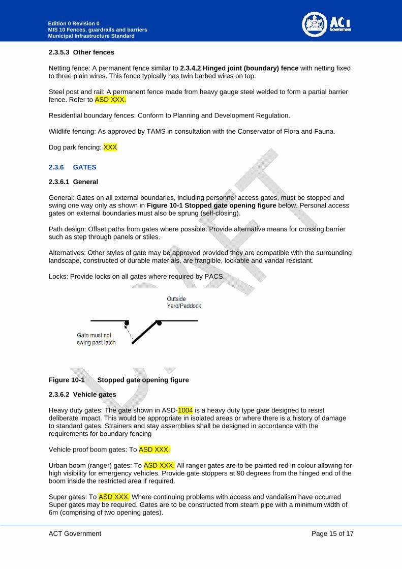
General: Gates on all external boundaries, including personnel access gates, must be stopped and swing one way only as shown in Figure 10-1 Stopped gate opening figure below. Personal access gates on external boundaries must also be sprung (self-closing).
Path design: Offset paths from gates where possible. Provide alternative means for crossing barrier such as step through panels or stiles.
Alternatives: Other styles of gate may be approved provided they are compatible with the surrounding landscape, constructed of durable materials, are frangible, lockable and vandal resistant.
Locks: Provide locks on all gates where required by PACS.
Figure 10-1 Stopped gate opening figure
2.3.6.2 Vehicle gates
Heavy duty gates: The gate shown in ASD-1004 is a heavy duty type gate designed to resist deliberate impact. This would be appropriate in isolated areas or where there is a history of damage to standard gates. Strainers and stay assemblies shall be designed in accordance with the requirements for boundary fencing
Vehicle proof boom gates: To ASD XXX.
Urban boom (ranger) gates: To ASD XXX. All ranger gates are to be painted red in colour allowing for high visibility for emergency vehicles. Provide gate stoppers at 90 degrees from the hinged end of the boom inside the restricted area if required.
Super gates: To ASD XXX. Where continuing problems with access and vandalism have occurred Super gates may be required. Gates are to be constructed from steam pipe with a minimum width of 6m (comprising of two opening gates).

ACT Government
Page 16 of 17
Edition 0 Revision 0 MIS 10 Fences, guardrails and barriers Municipal Infrastructure Standard
Flood gates: To be assessed with TAMS in each instance.
Signage: Provide signage for all ranger gates to ASD XXX.
2.3.6.3 Pedestrian access gates
General: Provide pedestrian access through fenced areas with personal access gates, bollard gates, step-through vehicle gates and step-through panels.
Step-through vehicle gates: Standard rural farm gate construction, 4.2m wide and 1.15m high. Refer to ASD XXX.
Personal access gates: Minimum 1.2m wide, 1.15m high galvanised CHS. This may be installed adjacent to a vehicle gate as an alternative to a step-through vehicle gate.
Cavalettis: To ASD XXX. Cavalettis will consist of a galvanised steel frame with treated pine logs.
2.4 DOCUMENTATION
Requirement: comply with Requirements for Design Acceptance Submissions (Attachment B).

ACT Government
Page 17 of 17
Edition 0 Revision 0 MIS 10 Fences, guardrails and barriers Municipal Infrastructure Standard
3 APPENDIX A – LEVEL CHANGES
3.1 GENERAL
General: This section provides commentary to the interpretation of the NCC in Municipal areas within lease boundaries administered by the ACT Government. This section does not take precedence over any requirements in the NCC.
Verge works: For level changes outside lease boundaries (i.e. within the verge) refer to the remainder of this Design Standard.
3.1.1 LEVEL CHANGES
Paved areas or areas within 5 m of a pedestrian path: Where changes in level are greater than 1 m (or 5 risers in the case of a stairway) in any direction, provide the following:
- Continuous protective balustrades; or
- Embankment slopes with grades less than 1 in 2.
Consideration for children: In school zones, shopping centres, playgrounds and other areas where there is likely large numbers of children and where the lower level has a hard surface such as concrete or gravel, the following shall apply:
- Barriers shall not have horizontal fence rails that can act as a ladder.
- Barriers shall not have gaps wide enough to enable children to climb through or narrow enough to get their heads stuck.
- The minimum acceptable level of protection uses vertical bars with maximum clear spacing of 110mm.
- The use of horizontal members alone shall not be permitted.
Other areas: In areas more than 5 metres from a pedestrian path but which meet the other criteria outlined above for needing a barrier, assess the most appropriate form of protection.
Safety screens: Assess the need to prevent objects being thrown from the top of steep embankments by undertaking a site specific risk assessment in accordance with the Bridge safety screen policy.