MUNICIPAL INFRASTRUCTURE · PDF fileMUNICIPAL INFRASTRUCTURE STANDARDS PART 3 PAVEMENT DESIGN...
22
MUNICIPAL INFRASTRUCTURE STANDARDS PART 3 PAVEMENT DESIGN Publication Number: MIS 03 Edition 0 Revision 0 Date of Effect: Supersedes: Design Standard for Urban Infrastructure Works Section 3 Edition 1 Revision 0 September 2002 Endorsed By: Approved By:
Transcript of MUNICIPAL INFRASTRUCTURE · PDF fileMUNICIPAL INFRASTRUCTURE STANDARDS PART 3 PAVEMENT DESIGN...
MUNICIPAL INFRASTRUCTURE
STANDARDS PART 3 PAVEMENT DESIGN
Publication Number: MIS 03 Edition 0 Revision 0 Date of Effect:
Supersedes:Design Standard for Urban Infrastructure Works Section 3 Edition 1 Revision 0 September 2002
Endorsed By:
Approved By:
Edition 0 Revision 0 MIS 03 Pavement design Municipal Infrastructure Standard
Document Information
Document Key Information
Document title MIS 03 Pavement design
Next review date
Key words
AUS-SPEC Base Document
0042 Pavement design
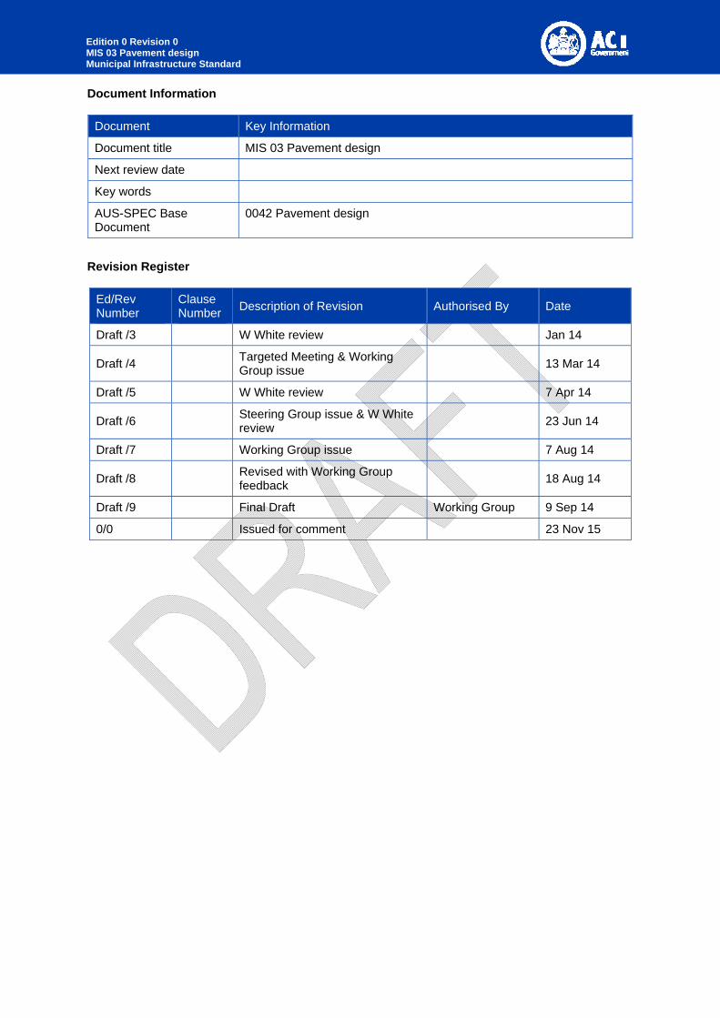
Revision Register
Ed/Rev Number
Clause Number
Description of Revision Authorised By Date
Draft /3 W White review Jan 14
Draft /4 Targeted Meeting & Working Group issue
13 Mar 14
Draft /5 W White review 7 Apr 14
Draft /6 Steering Group issue & W White review
23 Jun 14
Draft /7 Working Group issue 7 Aug 14
Draft /8 Revised with Working Group feedback
18 Aug 14
Draft /9 Final Draft Working Group 9 Sep 14
0/0 Issued for comment 23 Nov 15

Edition 0 Revision 0 MIS 03 Pavement design Municipal Infrastructure Standard
1 PREFACE
The Austroads series of Guides for provision and management of road and transport infrastructure provides a level of consistency across all jurisdictions in Australia and New Zealand. All road authorities have agreed to adopt the Austroads Guides as the primary technical reference, together with the relevant Australian and New Zealand Standards.
The Australian Capital Territory has adopted the Austroads Guides, and has issued a revised series of documents to reflect this development in standards and specifications for practice in the ACT. The ACT Government accepts the principles and general guidance in the Austroads Guide to Road Design. This Municipal Infrastructure Standard is issued to clarify any exceptions or additional requirements for implementation in the ACT, and to identify relevant complementary documents.
This present document is part of the ACT Municipal Infrastructure Standard (MIS) series spanning the broad scope of municipal infrastructure development and management in the ACT. Whilst based on the earlier Urban Services Design Standards for Urban Infrastructure Works, this document has been significantly expanded to incorporate new technologies and to bring it into line with Australian best practice. This revised series uses AUS-SPEC (October 2013) format wherever practical.
For the purposes of this series of standards, municipal infrastructure pertains to road works (except arterial and higher order roads), stormwater drainage and landscaping required to service residential, commercial and industrial estates for both greenfield and brownfield/urban in-fill developments. They are works to be owned and maintained by Territory and Municipal Services (TAMS) and to be constructed either by a developer and gifted to the ACT Government or constructed as part of the ACT Government Capital Works program. In all developments, if these Design Standards cannot be appropriately applied the proposed innovation should be discussed with and approved by TAMS.
Municipal Infrastructure Standards
MIS 01 Street planning and design
MIS 02 Earthworks and site grading
MIS 03 Pavement design
MIS 04 Subsurface drainage
MIS 05 Active Travel
MIS 06 Verges
MIS 07 Driveways
MIS 08 Stormwater
MIS 09 Bridges and related structures
MIS 10 Guardrails, fences and barriers
MIS 11 Off-street parking
MIS 12 Guide signs
MIS 13 Traffic Control Devices
MIS 14 Public lighting
MIS 15 Urban edge Management Zone
MIS 16 Urban open space
MIS 17 Shopping centres and other public urban spaces
MIS 19 Sports ground design
MIS 20 Street and park furniture and barbeques
MIS 21 Playgrounds and playground equipment
Edition 0 Revision 0 MIS 03 Pavement design Municipal Infrastructure Standard
MIS 23 Public toilets
MIS 24 Soft landscape design
MIS 25 Plant species for urban landscape projects
MIS 26 Irrigation
MIS 27 Signage for shopping centres and other urban spaces
Attachment A Drawings
Trunk Road Infrastructure Standards
TRIS 01 Road planning
TRIS 02 Road design
TRIS 03 Traffic management
TRIS 04 Road safety
TRIS 05 Asset management
TRIS 06 Pavement design
TRIS 07 Bridges and related structures
TRIS 08 Road tunnels
TRIS 09 Project delivery
TRIS 10 Project evaluation
Edition 0 Revision 0 MIS 03 Pavement design Municipal Infrastructure Standard
CONTENTS
1 Preface ............................................................................................................................................ 3
2 Pavement design ........................................................................................................................... 6
2.1 General .................................................................................................................................... 6
2.1.1 Responsibilities ................................................................................................................... 6
2.1.2 Cross references ................................................................................................................. 6
2.1.3 Referenced documents ....................................................................................................... 7
2.1.4 Standards ............................................................................................................................ 8
2.1.5 Interpretation ....................................................................................................................... 8
2.2 Pre-design planning .............................................................................................................. 10
2.2.1 Consultation ...................................................................................................................... 10
2.3 Design criteria ....................................................................................................................... 11
2.3.1 Pavement .......................................................................................................................... 11
2.3.2 Construction and maintenance ......................................................................................... 11
2.3.3 Environment ...................................................................................................................... 11
2.3.4 Subgrade Evaluation ......................................................................................................... 12
2.4 Materials ................................................................................................................................ 13
2.4.1 Unbound and modified granular materials ........................................................................ 13
2.4.2 Cementitiously bound materials ........................................................................................ 13
2.4.3 Asphalt materials ............................................................................................................... 13
2.4.4 Concrete materials ............................................................................................................ 14
2.4.5 Segmental Pavers ............................................................................................................. 14
2.4.6 Threshold treatments ........................................................................................................ 14
2.5 Design Traffic ........................................................................................................................ 14
2.5.1 Minor Road Traffic (flexible Pavements) ........................................................................... 14
2.5.2 Other Road Traffic ............................................................................................................. 15
2.6 Pavement design .................................................................................................................. 17
2.6.1 Pavement structure ........................................................................................................... 17
2.6.2 Surfacing ........................................................................................................................... 17
2.6.3 Surface Design .................................................................................................................. 18
2.6.4 Pavement Thickness design ............................................................................................. 19
2.7 Rehabilitation of existing pavements .................................................................................... 20
2.8 Documentation ...................................................................................................................... 20
3 Annexure A – Guide to Geotecnical investigations ................................................................. 22
3.1 General .................................................................................................................................. 22
LIST OF TABLES
Table 3-1 Minimum residential design traffic table ............................................................................ 15
Table 3-2 Asphalt surfacing table ...................................................................................................... 18
Table 3-3 Guide to Geotechnical investigations table ....................................................................... 22

Edition 0 Revision 0 MIS 03 Pavement design Municipal Infrastructure Standard
2 PAVEMENT DESIGN
2.1 GENERAL
2.1.1 RESPONSIBILITIES
2.1.1.1 Objectives
General: Design of road pavements to meet the required design life, based on the subgrade strength, traffic loading, climatic conditions, environmental factors, and the selection of appropriate materials for subgrade, subbase, base and wearing surface.
Scope: This Design Standard applies to Municipal roads in the ACT and does not apply to roads classified under the ACT Roads Hierarchy system as arterial or sub-arterial roads or to roads where the design traffic load is greater than 2 x 10⁶ ESA.
Pavement types: The pavement types covered by this Design Standard are:
- Flexible granular pavements: Flexible pavements consisting of granular pavement materials with thin bituminous surfacing.
- Stabilised pavements: Flexible pavements that include one or more cementitiously bound layers, created either in situ or in a plant.
- Deep lift DGA pavements: Flexible pavements consisting of predominantly asphaltic concrete layers.
- Segmental block pavements: Flexible pavements with segmental pavers surfacing.
- Concrete pavements: Rigid pavements in Municipal areas such as bus stops.
Trunk roads: Refer to TRIS 02 for the design of arterial or sub-arterial roads and roads where the design traffic load is greater than 2 x 10⁶ ESA.
2.1.1.2 Precedence
Requirement: Where any document except legislation or the Territory Plan issued in conjunction with this Design Standard includes technical requirements that conflict with this Design Standard the requirements of this Design Standard take precedence.
2.1.2 CROSS REFERENCES
2.1.2.1 Legislation
Heavy Vehicle National Law (ACT) Act 2013
Road Transport (General) Act 1999
Road Transport (Safety and Traffic Management) Act 1999
Road Transport (Safety and Traffic Management) Regulation 2000
Public Roads Act 1902
Public Unleased Land Act 2013
Territory Plan 2008 and General Codes
Work Health and Safety Act 2011
Edition 0 Revision 0 MIS 03 Pavement design Municipal Infrastructure Standard
2.1.2.2 Design Standards
General: The following Design Standards are related to this standard:
MIS 04 Subsurface drainage
MIS 05 Pedestrian and cyclist paths
TRIS 06 Pavement design
2.1.2.3 TAMS Reference Documents
Reference document 6 Design Acceptance submissions
Reference document 7 Operational acceptance submissions
Reference document 8 WAE quality records
Reference document 9 Final acceptance submissions
2.1.2.4 Design guides
General: The following ACT design guides are related to this standard:
MIS 04 Subsurface drainage
MIS 05 Active Travel
MIS 11 Off-street parking
Development Control Code for Best Practice Waste Management in the ACT (ACT No Waste)
2.1.2.5 Specifications
General: The following Specifications are related to this standard:
MITS 04 Flexible pavement construction
MITS 07 Segmental paving
TRITS 05 Rigid pavements
2.1.3 REFERENCED DOCUMENTS
2.1.3.1 Other publications
General: The following documents are incorporated into this design standard by reference:
Austroads
AGPT Austroads Guide to Pavement Technology
AGPT01:2009 Part 1 Introduction to pavement technology
AGPT02:2012 Part 2 Pavement structural design
AGPT03:2009 Part 3 Pavement surfacings.
AGPT04A:2008 Part 4A Granular base and subbase materials
AGPT04C:2009 Part 4C Materials for concrete road pavements
AGPT04K:2009 Part 4K Seals
AGPT05:2011 Part 5 Pavement evaluation and treatment design
AGPT06:2009 Part 6 Unsealed pavements
AGPT07:2009 Part 7 Pavement maintenance

Edition 0 Revision 0 MIS 03 Pavement design Municipal Infrastructure Standard
AGPT08:2009 Part 8 Pavement construction
AGRD Austroads Guide to Road Design
AGRD01: 2006 Part 1 Introduction to road design
AGRD02: 2006 Part 2 Design considerations
AGRD08:2009 Part 8 Process and documentation
AP-T85:2007 Optimum use of granular bases: material selection for detailed performance evaluation
AP-T68:2006 Update of the Austroads sprayed seal design method
Cement and Concrete Association of Australia
C&CAA-T51: 2004 Guide to Residential Streets and Paths
Concrete Masonry Association of Australia
CMAA-PA02: 2014 Concrete Segmental Pavements—Design guide for residential access ways and roads
Clay Brick and Paver Institute
CBPI Manual 1:2013 Clay paving design and construction
Techniques 15:1995 Design considerations for clay paved roadways
IPWEA (NSW)
Specification for supply of recycled materials for pavements, earthworks and drainage, 2010
2.1.4 STANDARDS
2.1.4.1 General
Standard: Road design To AGRD01, AGRD02 and Section 1 of this Design Standard.
Design considerations: To AGRD02 Table 3.1.
Pavement Structural Design: To AGPT02.
2.1.5 INTERPRETATION
2.1.5.1 Abbreviations
General: For the purposes of this Design Standard the following abbreviations apply:
AADT: Average Annual Daily Traffic.
ESA: Equivalent Standard Axles.
LATM: Local Area Traffic Management.
TAMS: Territory and Municipal Services, ACT Government and its successors.
Edition 0 Revision 0 MIS 03 Pavement design Municipal Infrastructure Standard
2.1.5.2 Definitions
General: For the purpose of this Design Standard, the definitions of terms used to define the components of the road reserve are in conformance with AS 1348, Glossary of Austroads Terms and AGRD03.
Other definitions that pertain to this Design Standard are outlined below,
- Concrete pavements: Rigid pavements in Municipal areas such as bus stops.
- Deep lift DGA pavements: Flexible pavements consisting of predominantly asphaltic concrete layers.
- Flexible granular pavements: Flexible pavements consisting of granular pavement materials with thin bituminous surfacing.
- Gravel pavements: Flexible pavements consisting of granular pavement materials without dust free surfacing.
- Municipal road: All roads which become part of the public road system and are supplementary to arterial and sub-arterial roads. Municipal roads include major collector roads, minor collector roads, access streets and rear access lanes. Municipal roads primary function is to provide access to leases/blocks. Refer to Estate Development Code for definition of each type of municipal road.
- Nominal kerb line: Also known as the nominal face of kerb, it is the location on the kerb, kerb and gutter or open concrete invert from which the road carriageway width is measured. Refer to Standard drawing DS3-01 for actual location for each kerb type.
- Path: A public access way for the movement of pedestrians, manually propelled vehicles and mobility scooters that is not located within a road.
- Pavement: The portion of a carriageway placed above the subgrade for the support of, and to form a running surface for, vehicular traffic.
- Restricted Access Vehicles: Vehicles that exceed a dimension or mass limit under ACT road transport laws.
- Restricted Access Vehicle routes: Approved routes for Restricted Access Vehicles which have been provided under ACT road transport laws.
- Road reserve: The strip of public land between abutting property boundaries, specifically gazetted for the provision of public right of way. It includes the road carriageway, as well as paths, verges and landscape.
- Segmental block pavements: Flexible pavements with segmental pavers surfacing.
- Stabilised pavements: Flexible pavements that include one or more cementitiously bound layers, created either in situ or in a plant.
- Upper Zone of Formation: The level immediately below the subgrade.

Edition 0 Revision 0 MIS 03 Pavement design Municipal Infrastructure Standard
2.2 PRE-DESIGN PLANNING
2.2.1 CONSULTATION
2.2.1.1 TAMS and other Authorities
Requirements: Consult with TAMS and other relevant Authorities during the preparation of design. In addition to the requirements of this Design Standard, identify the specific design requirements of these authorities.
2.2.1.2 Utilities services plans
Existing site conditions: Obtain plans from all relevant utilities and other organisations whose services, trees, important ecological habitats or other assets exist within the area of the proposed development. Plot this information on the relevant drawings including the plan and cross-sectional views. As a minimum, designs should refer to ‘Dial-before-you-dig’ information that is readily available in most areas.
Responsibility: Confirm service plans accuracy with onsite inspection and also potholing if deemed necessary.
2.2.1.3 Safety in Design
Requirement: Implement safety in design processes in accordance with the Work Health and Safety Act.
2.2.1.4 Proposed new services:
Requirement: Detail any new services proposed or relocated as part of the proposed works.
2.2.1.5 Protection of existing infrastructure
Requirement: Obtain drawings of existing infrastructure including landscaping within and at the interface to the site. Consult with the asset owners, where this is not covered by the Development Application process, to identify asset protection requirements.

Edition 0 Revision 0 MIS 03 Pavement design Municipal Infrastructure Standard
2.3 DESIGN CRITERIA
2.3.1 PAVEMENT
2.3.1.1 General
Gravel pavements: Flexible pavements consisting of granular pavement materials without dust free surfacing, should be considered only for remote rural roads, minor access roads or temporary roads, in each case where access is via an existing unsealed road.
2.3.1.2 Design variables
All proposed road pavements: Consider the following for Urban and rural roads (refer AGPT02):
- Construction and maintenance considerations.
- Noise requirements (e.g. as specified in approved Estate Development Plan).
- Environmental factors such as moisture conditions.
- Subgrade evaluation.
- Pavement and surfacing materials.
- Design traffic.
2.3.2 CONSTRUCTION AND MAINTENANCE
All proposed road pavements: Consider the following construction and maintenance factors for the type of pavement, choice of base and subbase materials, and the type of surfacing adopted:
- Documentation of joints incorporated in the design.
- Extent and type of drainage.
- Use of boxed or full width construction.
- Available equipment of the Contractor.
- Use of stabilisation.
- Dimensions of segmental paving units and layout of joints.
- Aesthetic, environmental and safety requirements.
- Social considerations including retention of noise performance.
- Construction under traffic.
- Use of staged construction.
- Ongoing and long-term maintenance costs.
2.3.3 ENVIRONMENT
The pavement design should consider relevant environmental factors in assessing the design subgrade strength and the choice of pavement and surfacing materials.

Edition 0 Revision 0 MIS 03 Pavement design Municipal Infrastructure Standard
2.3.4 SUBGRADE EVALUATION
2.3.4.1 Design considerations
General: Subgrade condition and design parameters should be assessed from subsurface investigations. Geotechnical investigations and designs must consider the following factors:
- Sequence of earthworks construction.
- The compaction moisture content and field density specified for construction.
- In situ moisture content at the time of subgrade assessment.
- Moisture changes during service life.
- Susceptibility to flooding.
- Subgrade variability.
- The presence or otherwise of weak layers below the design subgrade level particularly within the first 600mm below the subgrade level.
- Stabilisation requirements.
- Dispersive soils.
- Plasticity parameters.
- Swell characteristics.
- Salinity.
2.3.4.2 Geotechnical investigation
General: Subsurface investigations shall be carried out by a suitably experienced Geotechnical Engineer. Refer to Annexure A – Guide to Geotechnical investigations.
CBR Samples: Unless otherwise directed by the pavement designer, all samples for CBR testing shall be compacted to 100% Standard compaction and at Standard optimum moisture content, and tested after 4-day soaking under a 4.5 kg surcharge.
2.3.4.3 CBR considerations for Cut and Fill Design
General: Assessment of the Design CBR shall be based on laboratory soaked CBR values from relevant samples. For cut and fill in greenfield sites, adopt the 10th percentile low value, or if less than five results are available then the minimum of those results. Assessment of the design CBR below existing pavements should also take into account the results of the DCP testing.
Moisture content: The designer shall also consider the effect of potential moisture changes in the pavement and subgrade during the service life. If subsurface drainage is not proposed, if the pavement is likely to be subject to flooding or if the groundwater level is likely to be closer than 1.2 m to the subgrade, the Design CBR for cut and fill must allow for a greater variability in subgrade moisture content over the service life. In these instances the design moisture content shall be above the optimum moisture content.
2.3.4.4 Presentation of results
Submission: Include a summary of all laboratory and field test results and assumptions and/or calculations made in the assessment of the Design CBR for the cut and fill in the Pavement Design Report. Include the geotechnical investigation report in an Appendix.
Edition 0 Revision 0 MIS 03 Pavement design Municipal Infrastructure Standard
2.3.4.5 Upper Zone of Formation
Upper Zone of Formation: The subgrade is the level immediately below the pavement structure and the depth immediately below the subgrade level, as given in the Specification or drawings, is the Upper Zone of Formation, refer to MITS 02.
Minimum soaked CBR value: The Upper Zone of Formation materials for cut or fill zones for Municipal Roads shall have a soaked CBR value of at least 8%.
2.4 MATERIALS
General: Select appropriate pavement and surfacing materials, types, layer thicknesses and configurations to ensure that the pavement performs to its design functions and requires minimal maintenance under the anticipated traffic loading for the design life adopted.
2.4.1 UNBOUND AND MODIFIED GRANULAR MATERIALS
General: Unbound granular materials include modified granular materials as defined in AGPT02.
Material properties: To MITS 04.
Mechanistic design: If mechanistic design is required, refer to AGPT02 Table 6.1 for pavement material categories and design characteristics.
Recycled materials: Incorporate recycled materials to RMS 3051.
2.4.2 CEMENTITIOUSLY BOUND MATERIALS
General: Bound materials for Municipal roads are granular materials produced with addition of a binding agent to improve strength. The binding agent should be a slow setting cementitious material from a blend of cement, lime, flyash or slag.
Bituminous binders: To TRIS 06.
Material properties: Design parameters and performance criteria for cementitious stabilised materials are given in AGPT02.
2.4.3 ASPHALT MATERIALS
General: For Municipal road pavements, the binder is usually a standard bitumen product. The bitumen may be modified for special applications by the addition of specific polymers or foaming technologies.
Material designation: Asphalt types used in the ACT are identified as designated in RMS R116, R117, R119 and R121, comprising two or three letters to identify the mix type followed by a number identifying the nominal maximum aggregate size in mm, as follows:
- Dense graded asphalt (e.g. AC14);
- Open graded asphalt (e.g. OG14);
- Stone mastic asphalt (e.g. SMA10); and
- Fine gap graded asphalt (e.g. FGG07).
Dense graded asphalt: Note that both RMS R116 and R117 use the prefix ‘AC’ for dense graded asphalt mixes. However, the mixes are different. If both mixes are specified for a given project then the drawings must be clear about where each specification applies.
Material properties: Design parameters and performance criteria for asphalt materials are given in AGPT02.
Edition 0 Revision 0 MIS 03 Pavement design Municipal Infrastructure Standard
Material supply: At the present time (2014) only AR450 bitumen is readily available as the unmodified binder for asphalt. Designers should check on binder availability at regular intervals.
Cold weather conditions: The designer shall consult with TAMS on proposed asphalt materials if the design is intended to be placed in winter.
2.4.4 CONCRETE MATERIALS
General: Concrete in Municipal road applications is generally limited to specific applications such as bus stops or threshold pavements for access roads. These applications do not justify the use of non-standard concrete mixes. For larger concrete applications refer to TRIS 06.
Material designation: Use ‘N’ class concrete as defined by AS 1379. A minimum compressive strength of 32 MPa should be specified for road pavements that will be trafficked by heavy vehicles.
Material properties: The maximum flexural strength for pavement design with N32 concrete is 4.0 MPa, in accordance with AGPT02. For higher strength concrete the maximum flexural strength for design is 0.7 times the square root of the compressive strength.
2.4.5 SEGMENTAL PAVERS
Requirement: Segmental pavers to CMAA PA02, CBPI Manual 1 and MITS 07.
2.4.6 THRESHOLD TREATMENTS
General: The use of a paving material other than asphaltic concrete as a treatment to differentiate road function is permitted. A reinforced concrete base will be required in accordance with this Design Standard. Shallow pattern stencilled concrete is preferred over segmental pavers; however, both treatments will be accepted.
2.5 DESIGN TRAFFIC
2.5.1 GENERAL
Scope: This Design Standard applies only to flexible pavements for Municipal roads designed in accordance with the Estate Development Code, having a design traffic load less than or equal to 2 x 10⁶ ESA.
Design methodology: Design traffic values in accordance with Table 3-1 shall be applied for standard situations. However, these values do not cater for all situations, such as short term heavy loading or unique vehicle loadings. The designer shall evaluate expected traffic loadings over the design life of the pavement and adopt the relevant design methodology:
- Normal conditions: To Section 2.5.2 Minor road traffic (flexible pavements); or
- Any other conditions: To Section 2.5.3 Other road traffic.
2.5.2 MINOR ROAD TRAFFIC (FLEXIBLE PAVEMENTS)
Scope: This section applies only to flexible pavements for Municipal roads designed in accordance not subject to short term heavy loading similar to that described in AGPT02 Section 12.7.1.
Residential zones: Adopt Table 3-1 Minimum residential design traffic table for the design of flexible pavements for municipal roads for residential development and CZ5 zones:
Edition 0 Revision 0 MIS 03 Pavement design Municipal Infrastructure Standard
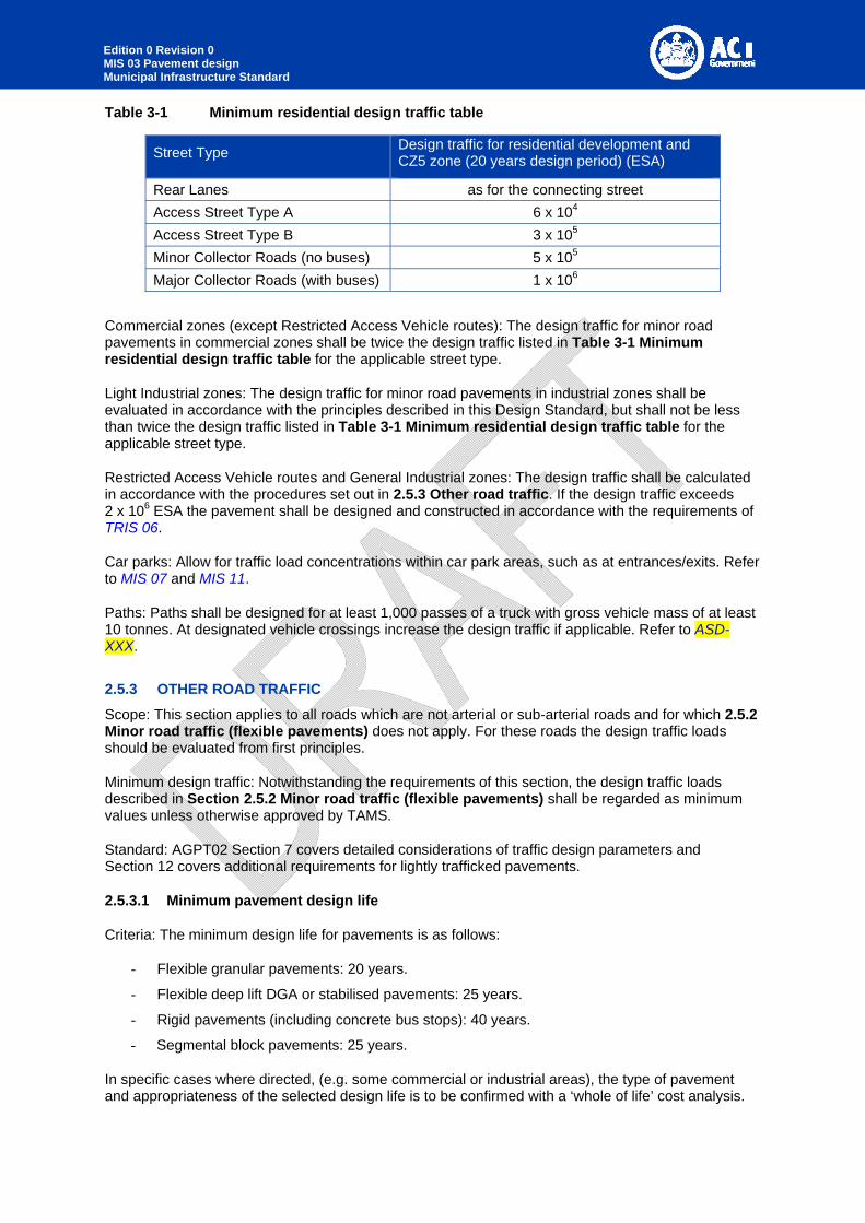
Table 3-1 Minimum residential design traffic table
Street Type Design traffic for residential development and CZ5 zone (20 years design period) (ESA)
Rear Lanes as for the connecting street
Access Street Type A 6 x 10⁴
Access Street Type B 3 x 10⁵
Minor Collector Roads (no buses) 5 x 10⁵
Major Collector Roads (with buses) 1 x 10⁶
Commercial zones (except Restricted Access Vehicle routes): The design traffic for minor road pavements in commercial zones shall be twice the design traffic listed in Table 3-1 Minimum residential design traffic table for the applicable street type.
Light Industrial zones: The design traffic for minor road pavements in industrial zones shall be evaluated in accordance with the principles described in this Design Standard, but shall not be less than twice the design traffic listed in Table 3-1 Minimum residential design traffic table for the applicable street type.
Restricted Access Vehicle routes and General Industrial zones: The design traffic shall be calculated in accordance with the procedures set out in 2.5.3 Other road traffic. If the design traffic exceeds 2 x 10⁶ ESA the pavement shall be designed and constructed in accordance with the requirements of TRIS 06.
Car parks: Allow for traffic load concentrations within car park areas, such as at entrances/exits. Refer to MIS 07 and MIS 11.
Paths: Paths shall be designed for at least 1,000 passes of a truck with gross vehicle mass of at least 10 tonnes. At designated vehicle crossings increase the design traffic if applicable. Refer to ASD-XXX.
2.5.3 OTHER ROAD TRAFFIC
Scope: This section applies to all roads which are not arterial or sub-arterial roads and for which 2.5.2 Minor road traffic (flexible pavements) does not apply. For these roads the design traffic loads should be evaluated from first principles.
Minimum design traffic: Notwithstanding the requirements of this section, the design traffic loads described in Section 2.5.2 Minor road traffic (flexible pavements) shall be regarded as minimum values unless otherwise approved by TAMS.
Standard: AGPT02 Section 7 covers detailed considerations of traffic design parameters and Section 12 covers additional requirements for lightly trafficked pavements.
2.5.3.1 Minimum pavement design life
Criteria: The minimum design life for pavements is as follows:
- Flexible granular pavements: 20 years.
- Flexible deep lift DGA or stabilised pavements: 25 years.
- Rigid pavements (including concrete bus stops): 40 years.
- Segmental block pavements: 25 years.
In specific cases where directed, (e.g. some commercial or industrial areas), the type of pavement and appropriateness of the selected design life is to be confirmed with a ‘whole of life’ cost analysis.
Edition 0 Revision 0 MIS 03 Pavement design Municipal Infrastructure Standard
2.5.3.2 Existing Traffic
Traffic Data: Existing traffic volumes and percentage heavy vehicles should be assessed from traffic counts if possible. Axle-pair counts from traffic signals can be obtained from Traffic Signals Branch, TAMS. For the purpose of calculation of AADT from peak hour traffic volumes, it should be assumed that average AM + PM peak hour traffic volumes represent between 10% and 12% of AADT.
2.5.3.3 Growth Rates
Criteria: The design growth rates should be selected based on results obtained from a traffic model calibrated for Canberra if applicable, on historical growth rates and on assessment of future demand.
2.5.3.4 Proportion Heavy Vehicles
Criteria: The proportion of heavy vehicles (Austroads vehicle Classes 3 to 12) used for pavement design should be selected based on traffic classification counts on similar roads and assessment of demand. A minimum value of 3% should be adopted unless data is available to indicate a lower value.
2.5.3.5 Design traffic volumes
Heavy vehicle traffic: The design total heavy vehicle traffic for the life of the road pavements should be calculated in accordance with AGPT02 Section 12.7 (Calculation of design traffic volumes for lightly trafficked roads) and AGPT02 Section 7 (Calculation of design traffic volumes approaching or exceeding 106 ESA). The total heavy vehicle traffic should allow for construction traffic loads for adjacent developments.
AGPT02 Table 7.4 provides the values of cumulative growth factor for a range of annual growth rates and design periods.
2.5.3.6 Design traffic loads - Equivalent Standard Axles (ESA)
Heavy vehicle traffic: The design traffic load shall be calculated by multiplying the design total heavy vehicle traffic by the average ESA per heavy vehicle. The average ESA per heavy vehicle for pavements carrying mixed heavy vehicle traffic shall be not less than the following default values (to be used in the absence of other information):
- for average number of heavy vehicles per lane per day (averaged over the design life) less than 16: 0.7 ESA per heavy vehicle
- for average number of heavy vehicles per lane per day (averaged over the design life) 16 or greater: 1.2 ESA per heavy vehicle
The average ESA per heavy vehicle for pavements carrying predominantly one or two types of commercial or industrial heavy vehicle shall be determined for those vehicle types assuming they are fully loaded.
Segmental pavements: For interlocking concrete segmental pavements, the simplification of replacing ESA’s with the number of heavy vehicles exceeding 3 tonne gross mass contained in CMAA PA02is acceptable up to a design traffic of 106 ESA. Beyond this, calculate the design ESA from first principles as stated above.
Rigid pavements: For rigid pavements, calculate the number of heavy vehicle axle groups (HVAG) based on the ESA/HVAG data in AGPT02 Table 12.2.
2.5.3.7 Presentation of results
Submission: Include a summary of all data sources, assumptions and results in the Pavement Design Report, and include the data and calculations in an Appendix.
Edition 0 Revision 0 MIS 03 Pavement design Municipal Infrastructure Standard
2.6 PAVEMENT DESIGN
2.6.1 PAVEMENT STRUCTURE
2.6.1.1 Pavement extent
Pavement extent: The pavement structure (typically the subbase layer) shall extend a minimum of 75 mm behind the rear face of any kerb and/or channel (gutter). If a kerb or gutter is not provided, the pavement shall extend at least 0.5 m outside the edge line.
2.6.1.2 Drainage
Precautions: Make provision for pavement layer drainage on the assumption that during the service life of the pavement ingress of water will occur.
Standard: MIS 04.
2.6.2 SURFACING
2.6.2.1 General
Requirement: Streets shall have a bituminous wearing surface as follows except where the pavement is designed for concrete or segmental block surfacing:
- Urban residential streets:
- Prime coat, plus asphalt.
- Commercial and industrial streets:
- Prime coat, plus asphalt.
- Maintenance access tracks:
- Prime coat, plus one or two coat sprayed seal, or
- Prime coat, plus asphalt.
- Temporary surfaces:
- Prime, plus one or two coat sprayed seal, or
- Primerseal.
Temporary protection: Where a primed surface is to be trafficked before the asphalt wearing course is applied, a primerseal shall be applied. Use prime plus seal where the surface is expected to be trafficked for more than 6 months.
2.6.2.2 Braking and turning zones
Surfacing requirements: For braking and turning zones the surfacing requirements are as follows:
- Roundabouts should have suitable pavements to resist shear loading, i.e., deep strength asphalt or concrete.
- For intersections and roundabouts where the design AADT> 3000, PMB should be used in the asphalt surfacing layer.
Edition 0 Revision 0 MIS 03 Pavement design Municipal Infrastructure Standard
2.6.3 SURFACE DESIGN
2.6.3.1 Sprayed bituminous seals
Standard: Sprayed bituminous seals, including primerseals, shall be designed in accordance with AP-T68-06, as updated.
Criteria: Primerseals should be specified with the following nominal aggregate sizes:
- 5-7 mm size aggregate for traffic less than or equal to 200 vehicles per lane per day.
- 7-10 mm size aggregate for traffic more than 200 vehicles per lane per day.
- 10 mm aggregate for very hot and/or wet conditions and traffic more than 600 vehicles per lane per day.
Double-double seals, comprising a minimum of two coats binder and two coats of aggregate shall use 10 mm size aggregate for the first coat and 7 or 5 mm size aggregate for the second coat unless otherwise agreed by TAMS.
Single coat sprayed seals shall use 10 mm size aggregate.
Other seal types in accordance with AP-T68-06, as updated, may be used subject to approval by TAMS.
2.6.3.2 Asphalt
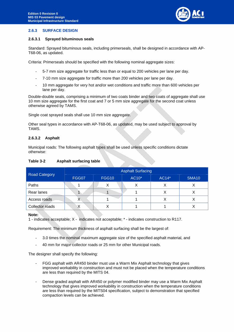
Municipal roads: The following asphalt types shall be used unless specific conditions dictate otherwise:
Table 3-2 Asphalt surfacing table
Road Category Asphalt Surfacing
FGG07 FGG10 AC10* AC14* SMA10
Paths 1 X X X X
Rear lanes 1 1 1 X X
Access roads X 1 1 X X
Collector roads X X 1 1 X
Note: 1 - indicates acceptable; X - indicates not acceptable; * - indicates construction to R117.
Requirement: The minimum thickness of asphalt surfacing shall be the largest of:
- 3.0 times the nominal maximum aggregate size of the specified asphalt material, and
- 40 mm for major collector roads or 25 mm for other Municipal roads.
The designer shall specify the following:
- FGG asphalt with AR450 binder must use a Warm Mix Asphalt technology that gives improved workability in construction and must not be placed when the temperature conditions are less than required by the MITS 04.
- Dense graded asphalt with AR450 or polymer modified binder may use a Warm Mix Asphalt technology that gives improved workability in construction when the temperature conditions are less than required by the MITS04 specification, subject to demonstration that specified compaction levels can be achieved.
Edition 0 Revision 0 MIS 03 Pavement design Municipal Infrastructure Standard
Prime or Primerseal coats shall be shown on the drawings below the asphalt surfacing.
2.6.3.3 Segmental pavers
Requirement: Segmental pavers for roads or trafficked areas to AS4455 and MITS 07.
Edge restraint: Design the edges of all paving to be constrained by either kerbing and/or guttering, or by concrete edge strips.
2.6.4 PAVEMENT THICKNESS DESIGN
2.6.4.1 Unbound granular flexible pavements – Bituminous surfaced
Low design traffic: Design unbound granular flexible pavements with thin bituminous surfacings, including those with cement or lime modified granular materials, with design traffic up to 105 ESA to AGPT02 Figure 12.2. For the purpose of the pavement design, FGG asphalt and seals shall not be considered as structural layers.
Moderate design traffic: For design traffic between 105 ESA and 106 ESA, design using AGPT02 Figure 8.4. For design traffic above 106 ESA, use AGPT02 Figure 8.4 (including adjustment for Standard Axle Repetitions and ESA) or mechanistic design in accordance with AGPT02 Chapter 8.
High design traffic: Pavements for roads with traffic exceeding 2 x 10⁶ ESA shall be designed in accordance with the requirements of TRIS 06.
Mechanistic design: For mechanistic design, granular materials layers above subgrade level shall be sub-layered in accordance with AGPT02 Section 8. Granular or stabilised materials used for Upper Zone of Formation materials shall not be sub-layered and shall have a maximum design vertical modulus of 150 MPa.
Select fill: Select fill materials, if required, must be specified as part of the Upper Zone of Formation in MITS 02.
2.6.4.2 Flexible pavements containing bound layers with asphalt surfacing
Mechanistic design: Design flexible pavements containing one or more bound layers, including cement stabilised layers or thick asphalt layers other than thin asphalt surfacings, using mechanistic design as set out in AGPT02 Section 8.
Design criteria: For mechanistic design of Municipal roads, a project reliability of 95% shall be used unless otherwise specified by TAMS. Design shall also take account of the variation in asphalt modulus with heavy vehicle speed as set out in AGPT02, using a design speed of 20 km/hr less than the posted speed limit.
Requirement: The pavement thickness shown on the drawings shall be at least 10 mm greater than the calculated thickness for thick asphalt pavements, or 20 mm greater for pavements containing cemented materials. The additional thickness shall be provided in the most critical layer for the design.
2.6.4.3 Rigid pavements
Criteria: Design rigid (concrete) pavements with design traffic up to 106 HVAG to either CCAA-T51 or AGPT02 Section 12.9. For design traffic above 106 HVAG design to AGPT02 Section 9.
The concrete base thickness shown on the drawings shall be at least 10 mm greater than the calculated thickness. The designer must detail all joint types and locations on the drawings – refer CCAA-T51 or NSW RMS Standard Drawings.

Edition 0 Revision 0 MIS 03 Pavement design Municipal Infrastructure Standard
Specification: RMS R83 Jointed Concrete Base is not considered appropriate for rigid pavements in municipal roads. Construction should be specified in accordance with MITS 04. The designer should include extensive notes on the drawings relating to requirements for joints, surface finishes, tolerances etc.
2.6.4.4 Concrete segmental pavements
Criteria: Design concrete segmental pavements with design traffic up to 106 estimated heavy vehicles exceeding 3 T gross to CMAA PA02.
2.6.4.5 Clay segmental pavements
Criteria: Design clay segmental pavements with design traffic up to 106 ESAs to CBPI Manual 1 and CBPI Techniques 15.
2.6.4.6 Minimum pavement thickness
Requirement: Irrespective of the pavement thickness calculated in Section 2.6.4.1 Unbound granular flexible pavements – Bituminous surfaced, the minimum pavement thickness, including the thickness of surfacings, is as follows:
- Roads with kerb and channel (gutter): 250 mm.
- Uncurbed roads: 200 mm.
- Car parks: 150 mm.
- Paths: 150 mm.
Subbase and base layers: refer to minimum layer thickness in MITS 04.
2.7 REHABILITATION OF EXISTING PAVEMENTS
Requirement: Comply with AGPT05 for investigation of existing sealed pavements and design of pavement treatments.
The surfacing type shall comply with noise requirements to the extent approved by TAMS. Ultra-thin asphalt or microsurfacing shall be acceptable as a resurfacing option subject to approval by TAMS.
2.8 DOCUMENTATION
Requirement: Comply with Requirements for Design Acceptance Submissions.
Construction specifications: Pavements designed under this Design Standard shall refer to MITS 04 or TRITS 05 for construction specifications. Pavements designed under TRIS 02 shall refer to TRITS 04 or TRITS 05 for construction specifications.
Where applicable, the following RMS Specifications include Annexures that must be completed by the pavement designer:
R44 Earthworks (for details regarding Upper Zone of Formation)
R71 Construction of Unbound and Modified Pavement Course
R73 Construction of Plant Mixed Heavily Bound Pavement Course
R75 Insitu Pavement Stabilisation using Slow Setting Binders
R106 Sprayed Bituminous Surfacing (with Cutback Bitumen)
R107 Sprayed Bituminous Surfacing (with Polymer Modified Binder)

Edition 0 Revision 0 MIS 03 Pavement design Municipal Infrastructure Standard
R110 Coloured Surface Coatings for Bus Lanes and Cycle ways
R116 Heavy Duty Dense Graded Asphalt
R117 Light Duty Dense Graded Asphalt
R119 Open Graded Asphalt
R121 Stone Mastic Asphalt
3051 Granular Base and Subbase Materials for Surfaced Road Pavements
3071 Selected Material for Formation
3151 Cover Aggregate for Sprayed Bituminous Surfacing
3152 Aggregates for Asphalt
Edition 0 Revision 0 MIS 03 Pavement design Municipal Infrastructure Standard
3 ANNEXURE A – GUIDE TO GEOTECNICAL INVESTIGATIONS
3.1 GENERAL
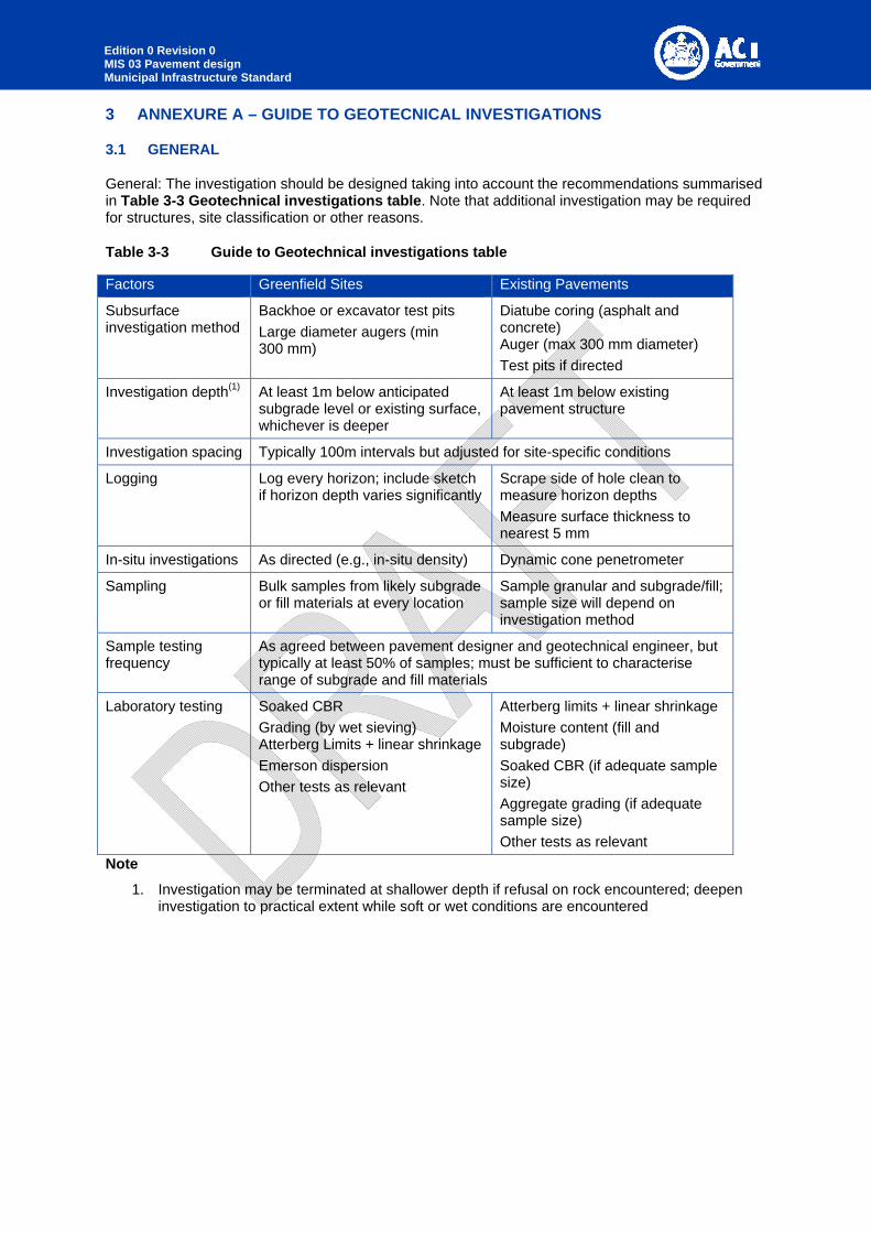
General: The investigation should be designed taking into account the recommendations summarised in Table 3-3 Geotechnical investigations table. Note that additional investigation may be required for structures, site classification or other reasons.
Table 3-3 Guide to Geotechnical investigations table
Factors Greenfield Sites Existing Pavements
Subsurface investigation method
Backhoe or excavator test pits
Large diameter augers (min 300 mm)
Diatube coring (asphalt and concrete) Auger (max 300 mm diameter)
Test pits if directed
Investigation depth(1) At least 1m below anticipated subgrade level or existing surface, whichever is deeper
At least 1m below existing pavement structure
Investigation spacing Typically 100m intervals but adjusted for site-specific conditions
Logging Log every horizon; include sketch if horizon depth varies significantly
Scrape side of hole clean to measure horizon depths
Measure surface thickness to nearest 5 mm
In-situ investigations As directed (e.g., in-situ density) Dynamic cone penetrometer
Sampling Bulk samples from likely subgrade or fill materials at every location
Sample granular and subgrade/fill; sample size will depend on investigation method
Sample testing frequency
As agreed between pavement designer and geotechnical engineer, but typically at least 50% of samples; must be sufficient to characterise range of subgrade and fill materials
Laboratory testing Soaked CBR
Grading (by wet sieving) Atterberg Limits + linear shrinkage
Emerson dispersion
Other tests as relevant
Atterberg limits + linear shrinkage
Moisture content (fill and subgrade)
Soaked CBR (if adequate sample size)
Aggregate grading (if adequate sample size)
Other tests as relevant
Note
1. Investigation may be terminated at shallower depth if refusal on rock encountered; deepen investigation to practical extent while soft or wet conditions are encountered