
Multiuser Project Collaboration with Autodesk® Civil 3D® environment. The lab is divided into two...
20
Walt Disney World Swan and Dolphin Resort Orlando, Florida 11/30/2005 - 10:00 am - 11:30 am Room:Mockingbird 1/2 [Lab] (Swan) Multiuser Project Collaboration with Autodesk® Civil 3D® Get up close and personal with the multiuser capabilities in Civil 3D. We'll have a network, data shortcuts, multiuser projects, and all kinds of cool stuff. We'll have you all doing all kinds of exercises and examples. CV32-1L About the Speaker: Mark Scacco - Engineered Efficiency, Inc. Dave Simeone; Robert Gadbaw (Assistant); Rad Lazic (Assistant) and Mark is the founder and president of Engineered Efficiency, Inc. and has been a consultant in the land development and construction industry for over a decade. He has experience in all phases of site development, and is still currently active as a civil engineer. Mark has been using Autodesk software since 1992 and has provided training and consulting to the civil, survey, and construction industries since 1998. He is certified at the Master level in AutoCAD, is a Tier 1 member of the AutoCAD Global Customer Council, is an Autodesk Certified Instructor, and has consulted as a Subject Matter Expert on Autodesk's Infrastructure Solutions products. Mark received his Civil Engineering degree from Purdue University, and is a registered Professional Engineer in Illinois. He is also a member of the American Society of Civil Engineers, the National Society of Professional Engineers, and the Geospatial Information & Technology Association, and teaches classes at Moraine Valley Community College. [email protected]
Transcript of Multiuser Project Collaboration with Autodesk® Civil 3D® environment. The lab is divided into two...

Walt Disney World Swan and Dolphin ResortOrlando, Florida
11/30/2005 - 10:00 am - 11:30 am Room:Mockingbird 1/2 [Lab] (Swan)
Multiuser Project Collaboration with Autodesk® Civil 3D®
Get up close and personal with the multiuser capabilities in Civil 3D. We'll have a network, data shortcuts, multiuser projects, and all kinds of cool stuff. We'll have you all doing all kinds of exercises and examples.
CV32-1L
About the Speaker:
Mark Scacco - Engineered Efficiency, Inc.Dave Simeone; Robert Gadbaw (Assistant); Rad Lazic (Assistant)and
Mark is the founder and president of Engineered Efficiency, Inc. and has been a consultant in the land development and construction industry for over a decade. He has experience in all phases of site development, and is still currently active as a civil engineer. Mark has been using Autodesk software since 1992 and has provided training and consulting to the civil, survey, and construction industries since 1998. He is certified at the Master level in AutoCAD, is a Tier 1 member of the AutoCAD Global Customer Council, is an Autodesk Certified Instructor, and has consulted as a Subject Matter Expert on Autodesk's Infrastructure Solutions products. Mark received his Civil Engineering degree from Purdue University, and is a registered Professional Engineer in Illinois. He is also a member of the American Society of Civil Engineers, the National Society of Professional Engineers, and the Geospatial Information & Technology Association, and teaches classes at Moraine Valley Community [email protected]


Lab CV32-IL
In this hands-on lab you will learn several features and methods for managing and sharing project data in a Civil 3D environment. The lab is divided into two segments: Civil 3D project management and Autodesk Sheet Set manager. The Civil 3D segment of this lab will walk you through the process of creating a Civil 3D project, adding source data into the project, and then referencing this data in for use in additional design tasks and then in the creation of production drafting. This segment is subdivided into two parts:
• The first part the Civil 3D segment will help you to understand how the broad project team can consume data that has been added into the project.
• The second part of this segment will take you through the process of adding additional design data to a project so that it can be referenced by the wider team.
The second segment of the class will take you through the process of using the Sheet Set Manager functionality that is included in Autodesk Civil 3D (and all other AutoCAD-based applications) as a data management and collaboration tool. You’ll learn to create sheet sets to manage drawings and data and how to publish your completed sheets.

Sharing Civil 3D project data in a project team environment
The first segment of this lab will focus on taking you through the steps of sharing core project data…
• COGO Points
• Surfaces
• Alignments
• Profiles
The benefits that you get from making use of the Civil 3D project capabilities include
• Additional data security
• Ability for multiple people to use one instance of project data simultaneously as part of the design and production drafting process
There are two methods of sharing project data in Civil 3D. They are as follows:
1. Shortcuts (Surfaces, Alignments, Profiles)
2. Check In/Out Central Project (Points)
The Project Data Sharing segment of this lab is broken into two sections. The first segment will help you to understand how the broad project team can consume data that has been added into the project. This is particularly important so that the team that is completing production drafting can make direct use of design data across many sheets. It also helps to reduce the risk of non-designers making unwanted modifications to the design elements in your Civil 3D model.
The second segment of this lab will take you through the process of adding additional design data to a project so that it can be referenced by the wider team.
1. Consumption of Civil 3D Project Data as part of the design and drafting process
a. Attach to a pre-existing Civil 3D Project (on server)
b. Reference the Existing Ground surface from this project. You will also display this surface using a different style than in the original drawing
c. Reference a road centerline and Existing and Proposed profiles from the project
d. Create a proposed corridor model
e. A series of design changes will be made to the source data so that you can learn how the changes affect your corridor design
f. You will create finished drafting elements in your drawing. After changes are once again made in the source design, you will see how this impacts your final drafting.
2. Process of adding design data into the project for consumption by others on the project team
a. You will create an alignment, and existing and design profile and than add these project elements to the project

b. You will create COGO Points along the alignment and add these into the Project Point database
c. Others will then reference these design elements in their drawings (used in the development of a corridor model)
d. You will then make a change to the corridor model (add superelevation parameters and make changes to the proposed vertical layout)
Section 1: Using Data that is stored in a Project
Connecting a Drawing to the Project In order to reference project data, you will need to add your drawing to a Civil 3D Project.
1. Create a new Drawing using the “_Autodesk Civil 3D Imperial By Layer.dwt”
2. Save the drawing into the project path and using the name of your PC as part of the file name.
a. The drawing must be saved prior to it being added to a project
b. File Name = Profile_001.dwg (use the number defined by the instructor)
c. Location: Drawings can be saved in any location. However, it is recommended that you save the drawings stored in a folder underneath the Civil 3D Project folder. In our lab, all drawings will be stored in the following way:
i. Drawings that include master data (data that will be referenced) are located in a read-only folder. This eliminates the risk of users making unwanted changes to the model. The location for these files will be: \Civil 3D Projects\AU Project lab\Drawings\Master Drawings
ii. Drawings that are referencing project data (plan/profile sheets, pipe systems, corridor models, etc) will be located in a folder that is open for read and write access. \Civil 3D Projects\AU Project lab\Drawings\Production Drawings
iii. Note – This is not a mandatory way of setting up your file structure in your daily work environment. Civil 3D does not require that you place files in any specific location.

3. Make sure that your Project Workspace is set to Master View. This will result in all open drawings and any projects in Civil 3D being visible in the workspace. This is controlled using the drop down list in the Workspace.
4. You will now Attach the drawing to the project. Right click on the desired drawing in the list of open drawings and select the Attach to Project… command

5. The final step is to select the project that you want to connect to. Select AU Project Lab as the project.
Note – As you create future projects, they will be listed in this selection dialog. Also, you can set project paths. These would also show up in this list. The image on the right shows two different project paths, each with multiple projects. We will demonstrate how you can create a New Project and New Project Path later in the session.

Referencing Data from the Project Now that the drawing is part of the project, we can begin referencing surfaces, alignments, and profiles.
6. Expand the AU Project Lab => Data Shortcuts item in the prospector view. You will see that we have shortcuts for the existing ground surface, proposed horizontal alignment, and the existing and proposed ground profiles along that alignment
7. Create a reference to the EG surface. Right click on the Data Shortcut and select the Create
Reference… command.

8. The Create Surface Reference dialog box allows you to name the surface and to set the render and object style. Note the following:
a. You should change the default name in the dialog to match the name of the original surface (EG)
b. You can use any display, render style, or layer that you want in this drawing. An important benefit of the Shortcut capability is that you can display the object differently in as many drawings as you’d like. This level of graphical control can not be achieved with AutoCAD X-references.
9. Explore some of the Display capabilities that you have with this reference surface.
a. Change the surface display from one style to another. Note that this change occurs only within this drawing.
b. Change the style (example, change contour range from 5’ to 1’ minor increment). This is set in the surface style => contour tab => contour intervals option of the dialog
10. You will not have any editing capabilities on this referenced surface. However, you do have access to all of the data in the surface (elevations, slopes, volumes, etc).
a. Expand the Surfaces => EG item in the Prospector (under the current drawing) and you will see the reference icon located next surface name. this indicates that it is a reference object. You will also notice that you have access the surface properties, but not to any of the editing commands.
b. Access the surface properties dialog and explore what information you have available for this surface and that all editing operations are disabled.

11. CHANGE MANAGEMENT – In this example, the surveyor has identified a location where the surface is
incorrect. The surveyor will fix this problem by editing the elevation of Point Number 380 from 169.873 to 219.873. This change will result in the surface being updated in the master drawing. When this file is saved, all users who have drawings open with this reference surface will be notified of this change and the object will be automatically updated.
12. The following steps will be performed by the instructor…
a. Open the COGO Points project drawing. Make certain that this is the active drawing. The current drawing will be displayed in a Bold font
b. Scroll to point number 380 under the Points item (in drawing view). Right click on point 380 and select the Checkout from Project command.
i. Note – if the point is protected in the project, you will need to change the setting to Unprotected (in the Project View).
ii. Points that have been checked out of a project will appear as a different icon. You will also notice the edit fields are accessible so that you can make changes to point values.
c. Edit the elevation of Point number 380. There are a number of ways you can make edits
including:
i. Panorama view or by graphical selection - Right Click on point number 380 and select the Edit Points command to edit the point elevation.

ii. Panorama view – select the edit field in the table view and edit data directly in the panorama view
d. Change the elevation to 219.873
e. Check the Point back into the Project and reset the protection value so that point 380 is protected. Note – you can set the protection control during the Check In process by selecting the “Check In and protect” option from the drop down list.
f. Save and Close the COGO Points drawing
g. Open Surface with Points drawing
h. Right Click at the Drawing name level of the prospector view, and run the Sync to Project command.
i. i. All Project Data that is out of sync will be listed and you can now choose whether you
want to update the drawing to match the Point data in the project.
j. In the Sync To Project dialog box, make certain that the toggle to Sync Data is toggled on for Point number 380 and select OK. This will update the point in the drawing. You should see that Point number 380 now has the correct elevation in the drawing.
k. Expand the surface tree in the drawing view and you will see that the surface is no longer up to date. Run the Rebuild surface command to update the surface to reflect the latest point data.

l. After rebuilding the surface, Save and Close the drawing
13. At this point, any sessions of Civil 3D that are actively viewing/editing drawings that referencing surface EG will receive a notification that the surface is out of date. If you select Synchronize, the drawing will update to reflect the updated object that you are referencing. If, for some reason, you do not wish to synchronize with the project, select the button in the upper right hand corner of the notification. You can choose to synchronize later if desired.
We will now reference the design alignment and profile (existing and proposed) so that we can design a simple corridor model
14. Expand the Data Shortcuts tree in your prospector view and right-click on the Elm - CL alignment to access the Create Reference command.
15. Just as with surfaces, the shortcut does not currently match the original alignment name.
a. Make sure that you type in the alignment name (Elm – CL). Note that this is not mandatory, but strongly recommended in practical use. The shortcut will still work properly if you use a different name.
b. You can set the style (object and annotation) to anything that you desire. This will only affect the way that the alignment and alignment labels appear in your drawing. The key concept to understand is that this technique allows many users with many drawings to represent design data differently per drawing.

16. The next step is to reference the Profiles (EG and FG) for the horizontal alignment. The process is essentially the same as when creating alignments. However, the profiles will not be displayed immediately in your drawing.
a. Make sure you input the proper the profile names when creating the profile reference (ie, the name of the original profile)
b. You will perform this same process for the existing and then the proposed ground profiles
17. Select the Create View command in the Profiles pulldown menu to insert the profiles in the drawing. Select any profile view style, band set, etc that you want. You can also choose to draft only a subset of the profile.
a. Tip – This is a method that you can use to create plan/profile sheets for a specific range of stations.
18. At this point you should have a drawing that contains references to a surface, alignment and existing and proposed profiles. Any changes to any of the original model elements will result in a your references being updated.
19. Try adding drafting elements and see how things adjust as changes are made to the base model. For
example…
a. Change the appearance of objects
b. Insert Station/Offset labels along the alignment

c. Add Profile Bands (superelevation, horizontal, vertical geometry bands)
d. Create an alignment segment table (dynamic)
i. Note – you must first label alignment segments in the drawing
e. Attempt to Edit the profile and Alignment. Notice that all data is accessible for review, but you cannot make any edits
f. The instructor will make some changes to the model and you should receive notification as these changes are saved. Please accept the prompt to synchronize data shortcuts.
20. Time Permitting: We will create an assembly and then build a corridor model. The instructor will once again make design changes resulting in updates to your drafting and the new corridor model that you have developed.
a. Use the LaneOutsideSuper subassembly with a shoulder and daylight slope
b. Build the corridor using the Centerline, Proposed profile, and this new subassembly
c. The instructor will add design speed and superelevation values to the alignment and save the drawing. This will result in your alignment being updated. Based on that, the corridor model should also update (because you are using a subassembly that is referencing superelevation settings).
Creating objects that others can reference We will now spend a few minutes reviewing how you create references that can be shared by others on the project team. Each lab station should design an Edge Of Pavement (EOP) horizontal alignment that will be used to control the corridor model.
• Students on the Right Side of the room should design the Right EOP
• Students on the Left side of the room should design the Left EOP
• You will use the following naming convention: ELM-EOP-R-001
• Each Lab station has a number – please use that as the number in the alignment name!
• Note; If there is enough time, students should experiment with other examples of data that can be added to the project. Some examples include…
o PROPOSED SURFACE based on the corridor model surface that you created
o A proposed EDGE OF PAVEMENT profile for the alignment that already exists in the project. Note – the profile needs to exist in the master drawing of the alignment. In other words, you cannot create a shortcut to an alignment and then create a profile if you want the profile to be added to the project as a data shortcut.
o A new Centerline alignment and profile
o Etc
21. Save your drawing.
22. Once your new EOP alignment has been created, highlight the EOP alignment and right click. Select the Create Data Shortcut command and a shortcut will be created.
a. Note, you can also access the command to create data shortcuts from within the Prospector data view

23. Save Your drawing
24. At this point, this alignment should now be accessible to anyone connected to this project. Reference an EOP alignment that you would like to add into your drawing. Once the alignment is in the drawing, use this EOP as a logical name assignment to control the alignment width. Once this is set, you should see the corridor update to match the EOP and CL definition. Note – if the original EOP alignment is modified and saved, you will receive a notification and the shortcut will update. This will result in the corridor also being updated!

And Now for Something Completely Different…
Now that we’ve deal with data shortcuts and reference files, let’s examine an underutilized portion of the Civil 3D package that can help in your project collaboration: Sheet Set Manager.
“Wait a minute!” you say, “We already have Sheet Sets in LDT!” Yes, but you’re not using them like this! The new Sheet Set Manager (SSM) that was included in Autocad 2005 is a new way to manage and produce large sets of plans with a few clicks.
In this exercise, we’re going to make a new sheet set from existing drawings, create a live, reactive Table of Contents, and look at plotting the whole set with fewer clicks than ever before.
1. In a blank drawing (or your current one,) open the Sheet Set Manager toolbar using the icon on the top row.
2. Click the dropdown menu in the SSM toolbar, and select New Sheet Set… to display the Create Sheet Set Wizard.
3. Because we’re using existing drawings, leave that radio button toggled, and click Next.
4. Change the Name to be AU2005 and enter a description if desired. It’s a good convention to use your firm’s Project Number as the Name and the Client or Agency as the Description.
5. Sheet set data files (.dst) can be stored anywhere you like. In this case, click and browse to the top level of the data set for this lab and click OK. You don’t have to pick a specific file, just stop at the folder you want to use. Sheet set files don’t have to be stored with the drawing!
6. Click the Sheet Set Properties button and modify your dialog to look like the one below and click OK, then Next. When browsing for the Sheet creation template, change the type to Drawing (dwg)
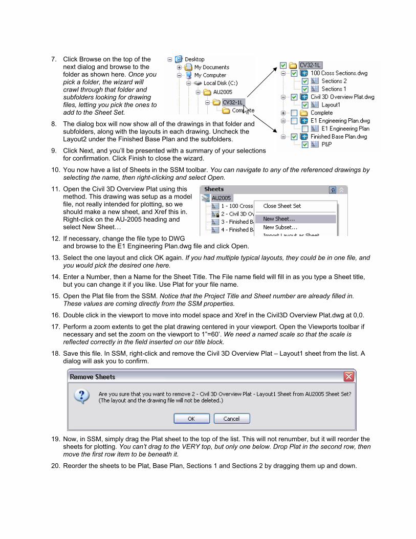
7. Click Browse on the top of the next dialog and browse to the folder as shown here. Once you pick a folder, the wizard will crawl through that folder and subfolders looking for drawing files, letting you pick the ones to add to the Sheet Set.
8. The dialog box will now show all of the drawings in that folder and subfolders, along with the layouts in each drawing. Uncheck the Layout2 under the Finished Base Plan and the subfolders.
9. Click Next, and you’ll be presented with a summary of your selections for confirmation. Click Finish to close the wizard.
10. You now have a list of Sheets in the SSM toolbar. You can navigate to any of the referenced drawings by selecting the name, then right-clicking and select Open.
11. Open the Civil 3D Overview Plat using this method. This drawing was setup as a model file, not really intended for plotting, so we should make a new sheet, and Xref this in. Right-click on the AU-2005 heading and select New Sheet…
12. If necessary, change the file type to DWG and browse to the E1 Engineering Plan.dwg file and click Open.
13. Select the one layout and click OK again. If you had multiple typical layouts, they could be in one file, and you would pick the desired one here.
14. Enter a Number, then a Name for the Sheet Title. The File name field will fill in as you type a Sheet title, but you can change it if you like. Use Plat for your file name.
15. Open the Plat file from the SSM. Notice that the Project Title and Sheet number are already filled in. These values are coming directly from the SSM properties.
16. Double click in the viewport to move into model space and Xref in the Civil3D Overview Plat.dwg at 0,0.
17. Perform a zoom extents to get the plat drawing centered in your viewport. Open the Viewports toolbar if necessary and set the zoom on the viewport to 1”=60’. We need a named scale so that the scale is reflected correctly in the field inserted on our title block.
18. Save this file. In SSM, right-click and remove the Civil 3D Overview Plat – Layout1 sheet from the list. A dialog will ask you to confirm.
19. Now, in SSM, simply drag the Plat sheet to the top of the list. This will not renumber, but it will reorder the
sheets for plotting. You can’t drag to the VERY top, but only one below. Drop Plat in the second row, then move the first row item to be beneath it.
20. Reorder the sheets to be Plat, Base Plan, Sections 1 and Sections 2 by dragging them up and down.
21. Our sheets need better names and are out of numeric order, so we’ll change the numbers an names by right-clicking on one and selecting Rename and Renumber
22. Clicking Next will cycle through the sheets, allowing you to update them all in one process. Edit the
number and Sheet title to match the list below.
Sheet Set Manager as a Data Source
Now you’ve got a sheet set that any member of your team can open, understand, and use to navigate. Let’s use it for a few more things. In this exercise, we’ll build a table of contents that responds to changes in the sheet set, and illustrate how a change in the sheet set can change a well built Title Block.
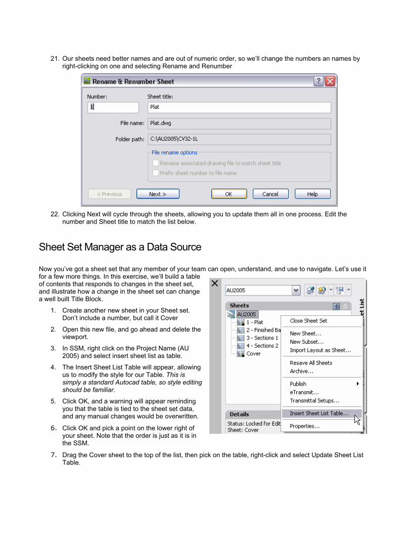
1. Create another new sheet in your Sheet set. Don’t include a number, but call it Cover
2. Open this new file, and go ahead and delete the viewport.
3. In SSM, right click on the Project Name (AU 2005) and select insert sheet list as table.
4. The Insert Sheet List Table will appear, allowing us to modify the style for our Table. This is simply a standard Autocad table, so style editing should be familiar.
5. Click OK, and a warning will appear reminding you that the table is tied to the sheet set data, and any manual changes would be overwritten.
6. Click OK and pick a point on the lower right of your sheet. Note that the order is just as it is in the SSM.
7. Drag the Cover sheet to the top of the list, then pick on the table, right-click and select Update Sheet List Table.

8. Finally, create a new MTEXT object in the middle of the page. Change the size to be 2” high, and then right-click in the mtext editor. Change the font to something a bit thicker since it’s a title.
9. Select Insert Field and the Field generator dialog appear. On the left drop down, select SheetSet as the Category, then CurrentSheetSetProjectName as the field name. Change the case if you like and click OK to dismiss the dialog.
10. Your title page now reflects the information from the sheet set, and each sheet also contains fields pointing to the sheet set for information about the project.
11. Right-click on the Sheet Set name, and select Properties. Since there was a new client brought in, we’ll change the Project Name to Scacco & Wedding. New ownership, that never happens, right?
12. Click OK to dismiss the dialog box.
13. Regen the drawing and notice that the fields have updated as shown at right. You can also regen each sheet to observe these changes.
Get it out!
In LDT, we’ve all experienced the frustration of jumping between drawings, plotting, waiting, jumping, plotting, waiting ad nauseam. Sheet Sets make plotting a breeze.
1. Open SSM if it’s not already, and open the AU2005 sheet set.
2. Click the Publish button at the top.
3. You can Publish to DWF, or more importantly, publish to a forced page setup using the Publish using Page Setup Override as shown below. This lets you publish all your sheets to a standard plot setting,
even if the user didn’t set up the page properly, or has modified the page setup for other uses.
The ability to use more of the project collaboration tools in the core autocad product is a marked change from LDT. A little time in setting up sheet sets will pay off quickly!