
Multitron Operating Manual - Marshall Scientific
161
Multitron Operating Manual 2020-08-20 We bring life to your laboratory.
Transcript of Multitron Operating Manual - Marshall Scientific
Multitron Operating Manual
2020-08-20
We bring life to your laboratory.

The best Multitron ever
Multitron – Rel. 4.0
Incubation Shaker
FW: 2.10
Doc-Nr. 77408 - EN
V.02.00 - Original
This operating manual can also be found online at:
www.infors-ht.com/en/multitron
Infors AG
Headoffice, Switzerland
Rittergasse 27
CH-4103 Bottmingen
T +41 (0)61 425 77 00
Multitron - Operating Manual
Table of Contents
20 August 2020 Page 1 of 158
1 General Information ............................................................... 7 1.1 About this Manual .......................................................... 7 1.2 Explanation of Special Notices ......................................... 8
1.2.1 Warning Notices .............................................. 8 1.2.2 Other Notices................................................... 8
1.3 Device Identification (Standard Identification Plate) ......... 9 1.4 Declaration of Conformity ............................................... 9 1.5 Customer Service and Services ........................................ 9
2 Safety and Responsibility .................................................... 10 2.1 Intended Use, Incorrect Use and Misuse ........................ 10 2.2 Cultivation Vessels to Be Used ....................................... 11 2.3 Qualified Personnel ....................................................... 13
2.3.1 Provider ......................................................... 13 2.3.2 User ............................................................... 13 2.3.3 Operator ........................................................ 14
2.4 Unauthorised Persons .................................................... 15 2.5 Responsibility of the Provider ......................................... 15 2.6 General Hazards ............................................................ 15
2.6.1 Electrical Current ........................................... 16 2.6.2 Unauthorised Spare Parts and Accessories ..... 16
2.7 Particular Hazards.......................................................... 16 2.7.1 Danger due to Hot Surfaces ........................... 17 2.7.2 Dangerous Gases ........................................... 17 2.7.3 Flammable or Explosive Substances ................ 17 2.7.4 Corrosive or Toxic Substances ........................ 17 2.7.5 Pathogenic Organisms ................................... 18
2.8 Safety Features .............................................................. 18 2.9 Warning Symbols on the Device .................................... 19 2.10 Declaration of Decontamination .................................... 20
3 Setup and Function .............................................................. 21 3.1 Setup of the Basic Unit .................................................. 21 3.2 Basic Functions .............................................................. 25
3.2.1 Standard Function Shaking ............................ 25 3.2.2 Standard Function Temperature Control
(Heating) ........................................................ 28 3.3 Connections and Interfaces ........................................... 29
3.3.1 Mains Connection ......................................... 29 3.3.2 Alarm Connection ......................................... 29 3.3.3 Ethernet Interface .......................................... 30
Multitron - Operating Manual
Table of Contents
Page 2 of 158 20 August 2020
3.4 Openings ...................................................................... 30 3.4.1 Discharge Outlet ............................................ 30 3.4.2 Ventilation Opening ....................................... 31 3.4.3 Air Vents ........................................................ 31
3.5 Interior Lighting............................................................. 32 3.6 Frames .......................................................................... 32 3.7 Operating and Indicating Elements ................................ 33
3.7.1 Power Switch ................................................. 33 3.7.2 Operating Panel ............................................. 33
3.8 Markings on the Device ................................................. 34 3.8.1 Identification Plate ......................................... 34 3.8.2 Identification of the Throw ............................ 34
4 Options .................................................................................. 35 4.1 Cooling ......................................................................... 35
4.1.1 Internal Cooling ............................................. 35 4.1.2 External Cooling ............................................ 37 4.1.3 Operating the Cooling Unit ............................ 38 4.1.4 Specifications and Technical Data .................. 38
4.2 Direct Steam Humidification .......................................... 39 4.2.1 Setup and Function ........................................ 39 4.2.2 Connection Conditions .................................. 40 4.2.3 Operating the Direct Steam Humidification .... 41 4.2.4 Specifications and Technical Data .................. 41
4.3 Pressure Elimination Unit for Direct Steam Humidification............................................................... 42 4.3.1 Setup and Function ........................................ 42 4.3.2 Cleaning the Pressure Elimination Unit ........... 43 4.3.3 Autoclaving the Pressure Elimination Unit ...... 45 4.3.4 Dimensions .................................................... 47 4.3.5 Specifications and Technical Data .................. 47
4.4 CO2 Control .................................................................. 48 4.4.1 Setup and Function ........................................ 48 4.4.2 Connection Conditions .................................. 49 4.4.3 Operating the CO2 Control ............................ 49 4.4.4 Specifications and Technical Data .................. 49
4.5 UV Decontamination ..................................................... 50 4.5.1 Setup and Function ........................................ 50 4.5.2 Operating the UV Decontamination ............... 50 4.5.3 Specifications and Technical Data .................. 50
4.6 Removable Shelf............................................................ 51
Multitron - Operating Manual
Table of Contents
20 August 2020 Page 3 of 158
4.7 LED Lighting .................................................................. 52 4.7.1 Setup and Function ........................................ 52 4.7.2 Operating the LED Lighting ............................ 52 4.7.3 Specifications and Technical Data .................. 52
4.8 Darkening ..................................................................... 53 4.9 Analog Output .............................................................. 53
4.9.1 Setup and Function ........................................ 53 4.9.2 Connection Assignment ................................. 53
4.10 Cable Pass-through ....................................................... 54 4.10.1 Setup and Function ........................................ 54 4.10.2 Using the Cable Pass-through ........................ 55
4.11 Antimicrobial Coating ................................................... 56
5 Accessories ............................................................................ 57 5.1 Trays ............................................................................. 57
5.1.1 Universal Table Tray ....................................... 57 5.1.2 Pre-Fitted Trays .............................................. 58 5.1.3 Tray with Sticky Stuff ..................................... 63
5.2 Clamps and Other Holders ............................................ 65 5.2.1 Clamps .......................................................... 66 5.2.2 Test Tube Holders .......................................... 67
5.3 Box for Microtitre Plates ................................................ 68 5.4 eve® .............................................................................. 71
6 Installation ............................................................................ 72 6.1 Operating Conditions at the Installation Location .......... 72 6.2 Requirements for the Mains Connection ....................... 73 6.3 Minimum Distances to the Device ................................. 74
7 Operation .............................................................................. 76 7.1 Switching on the Device ................................................ 76 7.2 Loading the Device ........................................................ 76
7.2.1 Opening the Door .......................................... 76 7.2.2 Inserting and Removing the Tray .................... 77 7.2.3 Fitting the Holders ......................................... 80 7.2.4 Tips & Tricks for Loading the Tray .................. 82
7.3 Overview about the Display und Controls ...................... 84 7.3.1 Display Area................................................... 85 7.3.2 Signs and Messages Regarding the Timer
Function ........................................................ 86 7.3.3 Error, Warning, and Alarm Signs .................... 87 7.3.4 Operating Panel ............................................. 88

Multitron - Operating Manual
Table of Contents
Page 4 of 158 20 August 2020
7.4 Adjusting, Activating and Deactivating Parameters ........ 90 7.4.1 Overview about the Parameters ..................... 90 7.4.2 Setting the Parameter Setpoints ..................... 92 7.4.3 Turning a Parameter On or Off ...................... 93
7.5 Timer Function .............................................................. 95 7.5.1 Overview ....................................................... 95 7.5.2 Programming the Timer - Single Change ....... 99 7.5.3 Programming the Timer - Cyclic Change ...... 104 7.5.4 Changing Timer Settings during Activated
Timer Function ............................................. 105 7.5.5 Changing Parameter Setpoint Values
during Activated Timer Function .................. 106 7.5.6 Stopping the Timer Function ........................ 107
7.6 Using eve® to Operate the Device ................................ 109 7.7 Settings Menu (Option Function) ................................. 111
7.7.1 Setting the Upper Limit for the Rotation Speed .......................................................... 111
7.7.2 Setting the Upper Limit for the Temperature ................................................ 112
7.7.3 Setting the Lower Limit for the Temperature ................................................ 112
7.7.4 Setting the Brake Force for Stopping the Table ........................................................... 112
7.7.5 Activating or Deactivating the Key Pad Lock (with a PIN) .......................................... 113
7.7.6 Activating or Deactivating the Key Tone ...... 113 7.7.7 Setting the Interior Lighting ......................... 114 7.7.8 Activating or Deactivating the Timer
Function ...................................................... 114 7.7.9 Setting up Data Exchange via Ethernet ........ 115 7.7.10 Setting the Height Above Sea Level
(Altimeter) ................................................... 115 7.7.11 Activating or Deactivating the Door Alarm ... 115 7.7.12 Humidity – Switch On/Off High Alarm ......... 116
7.8 Setting the Adjustable Throw ...................................... 116 7.9 Switching Off the Device ............................................. 117 7.10 Behaviour in Case of Interrupted Power Supply ........... 117

Multitron - Operating Manual
Table of Contents
20 August 2020 Page 5 of 158
8 Rectifying Faults ................................................................. 118 8.1 Alarm Messages .......................................................... 119
8.1.1 Parameter Alarms (High / Low) ..................... 119 8.1.2 Alarm Message RESTARTED ......................... 119
8.2 Faults and Error Messages ........................................... 120 8.2.1 Error Messages Explained ............................. 120 8.2.2 Fault Tables.................................................. 123
8.3 Replacing Fuses ........................................................... 127 8.4 Returning for Repair .................................................... 127
9 Maintenance and Cleaning ................................................ 128 9.1 Maintenance ............................................................... 128 9.2 Cleaning and Disinfection ........................................... 129
9.2.1 Cleaning ...................................................... 129 9.2.2 Disinfection.................................................. 132
10 Transport and Storage ....................................................... 133 10.1 Transport .................................................................... 133 10.2 Storage ....................................................................... 133
11 Disassembly and Disposal .................................................. 134 11.1 Disassembly ................................................................. 134 11.2 Disposal ...................................................................... 135
12 Technical Data and Specifications ..................................... 136 12.1 Dimension Drawings ................................................... 136 12.2 Connections ................................................................ 138 12.3 Specifications of the Basic Unit .................................... 140
12.3.1 Weight and Dimensions ............................... 140 12.3.2 Electrical Connection and Power Values ....... 141 12.3.3 Connections and Interfaces .......................... 141 12.3.4 Interior Lighting ........................................... 142 12.3.5 Material ....................................................... 142 12.3.6 Emissions ..................................................... 142 12.3.7 Operating Conditions .................................. 142 12.3.8 Protection Type ............................................ 143 12.3.9 Operating and Auxiliary Materials ................ 143
12.4 Specifications of Standard Parameters ......................... 144 12.4.1 Rotation Speed Parameter (Shaker Drive) ..... 144 12.4.2 Temperature Parameter (Heating and
Ventilation) .................................................. 145
Multitron - Operating Manual
Table of Contents
Page 6 of 158 20 August 2020
12.5 Specifications of the Options ....................................... 145 12.5.1 Internal Cooling ........................................... 145 12.5.2 External Cooling .......................................... 147 12.5.3 Direct Steam Humidification ........................ 148 12.5.4 Pressure Elimination Unit for Direct Steam
Humidification ............................................. 149 12.5.5 CO2 Control ................................................. 150 12.5.6 UV Decontamination ................................... 151 12.5.7 LED Lighting ................................................ 151
13 EC-Declaration of Conformity ........................................... 152
14 Index .................................................................................... 153

Multitron - Operating Manual
General Information
20 August 2020 Page 7 of 158
1 General Information
1.1 About this Manual
This manual enables the safe and efficient handling of the device.
All the information and instructions in this operating manual comply with the current standards, legal regulations, the latest technological and scientific developments and the knowledge gained from the manufacturer’s many years of experience in this field.
This operating manual is a component part of the device. It must be kept near to the device and must be accessible to the operators at all times. The users must read the operating manual thoroughly and fully un-derstand its contents before beginning any work. Adhering to all the safety and operating instructions in this manual is essential to ensure that work is carried out safely.
The scope of delivery may differ from the explanations, descriptions and figures in this operating manual due to special designs, addi-tional options specified on ordering and the latest technical/mechani-cal modifications.
This manual contains illustrations to aid general understanding. These may differ from the actual device as supplied.
Multitron - Operating Manual
General Information
Page 8 of 158 20 August 2020
1.2 Explanation of Special Notices
1.2.1 Warning Notices
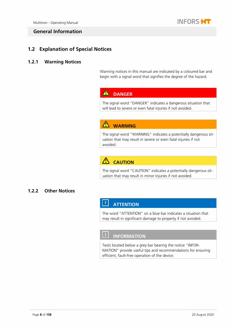
Warning notices in this manual are indicated by a coloured bar and begin with a signal word that signifies the degree of the hazard.
DANGER
The signal word “DANGER” indicates a dangerous situation that will lead to severe or even fatal injuries if not avoided.
WARNING
The signal word “WARNING” indicates a potentially dangerous sit-uation that may result in severe or even fatal injuries if not avoided.
CAUTION
The signal word “CAUTION” indicates a potentially dangerous sit-uation that may result in minor injuries if not avoided.
1.2.2 Other Notices
ATTENTION
The word “ATTENTION” on a blue bar indicates a situation that may result in significant damage to property if not avoided.
INFORMATION
Texts located below a grey bar bearing the notice “INFOR-MATION” provide useful tips and recommendations for ensuring efficient, fault-free operation of the device.
Multitron - Operating Manual
General Information
20 August 2020 Page 9 of 158
1.3 Device Identification (Standard Identification Plate)
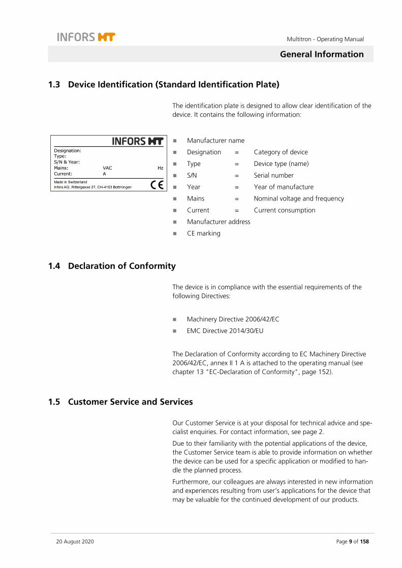
The identification plate is designed to allow clear identification of the device. It contains the following information:
Manufacturer name
Designation = Category of device
Type = Device type (name)
S/N = Serial number
Year = Year of manufacture
Mains = Nominal voltage and frequency
Current = Current consumption
Manufacturer address
CE marking
1.4 Declaration of Conformity
The device is in compliance with the essential requirements of the following Directives:
Machinery Directive 2006/42/EC
EMC Directive 2014/30/EU
The Declaration of Conformity according to EC Machinery Directive 2006/42/EC, annex II 1 A is attached to the operating manual (see chapter 13 "EC-Declaration of Conformity", page 152).
1.5 Customer Service and Services
Our Customer Service is at your disposal for technical advice and spe-cialist enquiries. For contact information, see page 2.
Due to their familiarity with the potential applications of the device, the Customer Service team is able to provide information on whether the device can be used for a specific application or modified to han-dle the planned process.
Furthermore, our colleagues are always interested in new information and experiences resulting from user’s applications for the device that may be valuable for the continued development of our products.

Multitron - Operating Manual
Safety and Responsibility
Page 10 of 158 20 August 2020
2 Safety and Responsibility
This section describes general considerations relating to user safety that must be taken into account when working with the device.
In the remaining sections, warning notices are used only to highlight particular hazards directly arising from the actions being described in the section in question.
It is essential to read the operating manual carefully – espe-cially this section and the warning notices in the text – and to follow the instructions therein.
This section also refers to areas that are the responsibility of the pro-vider due to certain risks arising from particular applications for which the device is used deliberately and with full awareness of the associ-ated risks.
2.1 Intended Use, Incorrect Use and Misuse
Depending on its features, the device is designed to be used as an incubation shaker for cultivating microorganisms or cell cultures under the following conditions:
Cultivation of non-pathogenic microorganisms or cell cultures of risk category 1 in a biotechnology labora-tory of biological protection level 1.
Cultivation of pathogenic microorganisms or cell cul-tures of risk category 2 in a biotechnology laboratory of biological protection level 2.
When using the device in protection level 2, users are respon-sible for taking appropriate protective measures to ensure that organisms cannot escape uncontrollably due to flask breakage, unintentional detaching of the sterile seal or simi-lar.
WARNING
The device is designed and constructed exclusively for the intended use described above.
Each instance of non-conventional use is considered as misuse and may lead to dangerous situations.

Multitron - Operating Manual
Safety and Responsibility
20 August 2020 Page 11 of 158
Intended use also includes following all the instructions in this man-ual, especially those relating to:
The installation site
Use of suitable cultivation vessels
User qualifications
Permissible parameter setpoints
Correct operation and maintenance
Any failure to observe the requirements specified in this manual shall be deemed incorrect use, in particular, use of inappropriate cultiva-tion vessels and/or unsuitable holders at speeds that are too high.
Any use of the device outside the scope of the intended use as de-scribed above shall be deemed misuse. This also applies to applica-tions for which the device is not designed, especially the following:
The device is not protected against explosions. Use and manu-facture of explosive gases as well as operating the device in the Ex area are therefore not permitted.
The device is not designed to sufficiently protect its users if path-ogenic organisms escape uncontrollably. Cultivation of patho-genic organisms of risk categories 3 and 4 is therefore not per-mitted.
To use the device for special applications not covered by conven-tional, intended use, the device must be modified and certified ac-cordingly by the manufacturer.
Any use of the device outside of a biotechnology laboratory, i.e. in any environment in which the conditions required for the safety of users cannot be met or cannot be met to their full extent, shall also be deemed misuse.
2.2 Cultivation Vessels to Be Used
Significant forces are applied to cultivation vessels, in particular in case of large vessels and high speeds. Hence, the cultivation vessels used are particularly significant in relation to user safety.
ATTENTION
Use of unsuitable or defective cultivation vessels can lead to glass breakage and therefore damage to property.
Multitron - Operating Manual
Safety and Responsibility
Page 12 of 158 20 August 2020
Approved cultivation vessels
The device has been designed for use with the following vessels using the holders designed specifically for them:
Erlenmeyer flasks up to 5,000 mL made of borosilicate glass (e.g. Schott Duran®) or high-grade plastic, such as polycarbonate (z. B. Corning®) etc.
Fernbach flasks up to 3,000 mL made of borosilicate glass (e.g. Schott Duran®) or high-grade plastic, such as polycarbonate (z. B. Corning®) etc.
Other vessels with the holders designed for them:
Test tubes
Centrifuge tubes
Microtitre plates
Deep well plates
To avoid the vessels coming out of the clamps at very high speeds, they might have to be secured using cable ties underneath the springs or some other suitable measure.
Cultivating organisms of risk category 2
When cultivating pathogenic organisms of risk category 2, special measures must be taken to stop the organisms from escaping. The user is responsible for this.
When using the device under protection category 2, stainless steel clamps of the correct size must be used to affix the flasks. Due to lim-ited resistance to disinfectants as well as the risk of unintentional de-taching of flasks, Sticky Stuff adhesive matting is not suitable for this purpose.
We further recommend using disposable plastic flasks with screw tops and filter membranes. We recommend using sticky tape to se-cure the lid against loosening unintentionally. Using glass flasks with cotton wool or paper plugs is not sufficiently safe.
Trays with Sticky Stuff
INFORMATION
For trays with Sticky Stuff, special provisions apply in relation to maximum permitted speeds. These must be observed to prevent cultivation vessels from detaching.
For detailed information see chapter 5.1.3 "Tray with Sticky Stuff", page 63.
Multitron - Operating Manual
Safety and Responsibility
20 August 2020 Page 13 of 158
2.3 Qualified Personnel
Due to the complexity of the device and the potential risks arising from its operation, the device may only be used by qualified, special-ist personnel.
2.3.1 Provider
The term “provider” applies to all persons who are responsible for making the device and the necessary infrastructure available. These persons may also be included in the group of people known as “us-ers”, though this is not always the case.
Irrespective of whether a provider is a member of the company’s board of management or a supervisor, they bear a special level of responsibility with regard to the processes and the qualification and safety of the users.
2.3.2 User
General
The term “user” applies to all persons who come into contact with the device in any way and perform work on or with it. This primarily applies to the following activities, which can be performed by the manufacturer’s own specialists or a variety of other persons (it is not always possible to distinguish clearly between the different types of person):
Assembly, installation and commissioning
Definition and preparation of the process
Operation
Troubleshooting and remedying of faults
Maintenance and cleaning (autoclaving, if necessary)
Service work and repairs
Disassembly, disposal and recycling
Qualified personnel
On account of their specific education, training and – in many cases – experience, the qualified personnel required for this work are able to recognise risks and respond accordingly to potential hazards.
The qualified personnel (either internal or external) who cannot be categorised under the separate “operators” group are made up of the following groups of persons:
Multitron - Operating Manual
Safety and Responsibility
Page 14 of 158 20 August 2020
Electricians (electrical engineers)
Decontamination specialists
Repair specialists
Specialists in disassembly and (environmentally friendly) disposal
Recycling specialists
2.3.3 Operator
The “operators” are a specific sub-group of users distinguished by the fact that they work with the device. They are the true target audi-ence for this operating manual.
Qualified technicians
Only technicians who have been trained for working in a biotechnol-ogy laboratory can be considered for the role of operator. These in-clude:
Process technicians in the fields of biotechnology and chemistry
Biotechnologists (biotechnicians)
Chemists with a specialisation in biochemistry; chemists in the field of organic chemistry or biochemistry
Life scientists (biologists) with special education in cytology, bac-teriology, molecular biology, genetics, etc.
Lab assistants (lab technicians) from various fields
In order to be classed as a “sufficiently qualified technician” for the operation of the device, the persons in question must have received thorough training and have read and understood the operating man-ual.
The operator must be informed in a training session provided by the provider of the tasks delegated to the operator and the potential risks of improper conduct. Tasks that go beyond the scope of operation under normal conditions may only be performed by the operator if this is specified in the manual and the provider has explicitly en-trusted said tasks to the operator.
Technicians in training
Persons in this group who are undergoing training or apprenticeships are only permitted to use the device under supervision and in accord-ance with the instructions of a trained and qualified technician.
Multitron - Operating Manual
Safety and Responsibility
20 August 2020 Page 15 of 158
2.4 Unauthorised Persons
The term “unauthorised persons” applies to all persons who can ac-cess the work area but are not qualified to use the device in accord-ance with the aforementioned requirements.
Unauthorised persons are not permitted to operate the device or use it in any other way.
2.5 Responsibility of the Provider
The device is used for industrial and scientific purposes. As such, the provider of the device is individually liable with regard to the legal requirements relating to occupational health and safety in a biotech-nology laboratory. In particular:
The provider is responsible for ensuring that the work and envi-ronmental regulations applicable in a biotechnology laboratory are observed.
The provider must ensure that the device remains in safe and proper working condition throughout its entire term of use.
The provider must ensure that all safety equipment is fully func-tional and is not disabled.
The provider must ensure that the device is only worked on by qualified users, and that said users receive sufficient training.
The provider must ensure that the protective equipment re-quired for working with the device is provided and worn.
The provider must ensure that this operating manual remains in the immediate vicinity of the device throughout its entire term of use.
2.6 General Hazards
This section covers general hazards and residual risks that are always present when using the device in accordance with normal, intended use.
The following notices are general in nature. As such, with a few ex-ceptions they are not repeated in the remaining sections.

Multitron - Operating Manual
Safety and Responsibility
Page 16 of 158 20 August 2020
2.6.1 Electrical Current
The device is operated electronically. There is an immediate risk of fa-tal injury if contact is made with live parts. The following points must be observed in order to avoid the risk of fatal injury:
In case of damage to insulation, disconnect the device from the mains immediately and arrange for it to be repaired.
Disconnect the device from the mains before commencing any work on the electrical system.
Always use qualified electricians for any work on the electrical system.
Disconnect the device from the mains before beginning any maintenance, cleaning or repair work.
Do not bypass any fuses or take them out of operation.
When replacing fuses, ensure they have the correct number of Amperes.
If the power cable is defective, replace it with a power cable of the same type.
Keep moisture away from live parts. It may lead to a short cir-cuit.
Never remove covers from the casing.
2.6.2 Unauthorised Spare Parts and Accessories
Incorrect or imitated spare parts and accessories as well as spare parts or accessories that have not been authorised by the manufacturer represent a significant safety risk. As such, we recommend procuring all spare parts and accessories from an authorised dealer or directly from the manufacturer. For the contact details of the manufacturer’s representatives, see page 2.
2.7 Particular Hazards
This section covers particular hazards and residual risks that may arise when using the device for special applications in accordance with normal, intended use.
Since the use of the device for such applications is deliberate, it is the responsibility of the operators and the provider to ensure that all per-sonnel are protected from potential damage to health. The provider is responsible for ensuring that the appropriate protective equipment for such applications is provided, and that the necessary infrastruc-ture is in place.
Multitron - Operating Manual
Safety and Responsibility
20 August 2020 Page 17 of 158
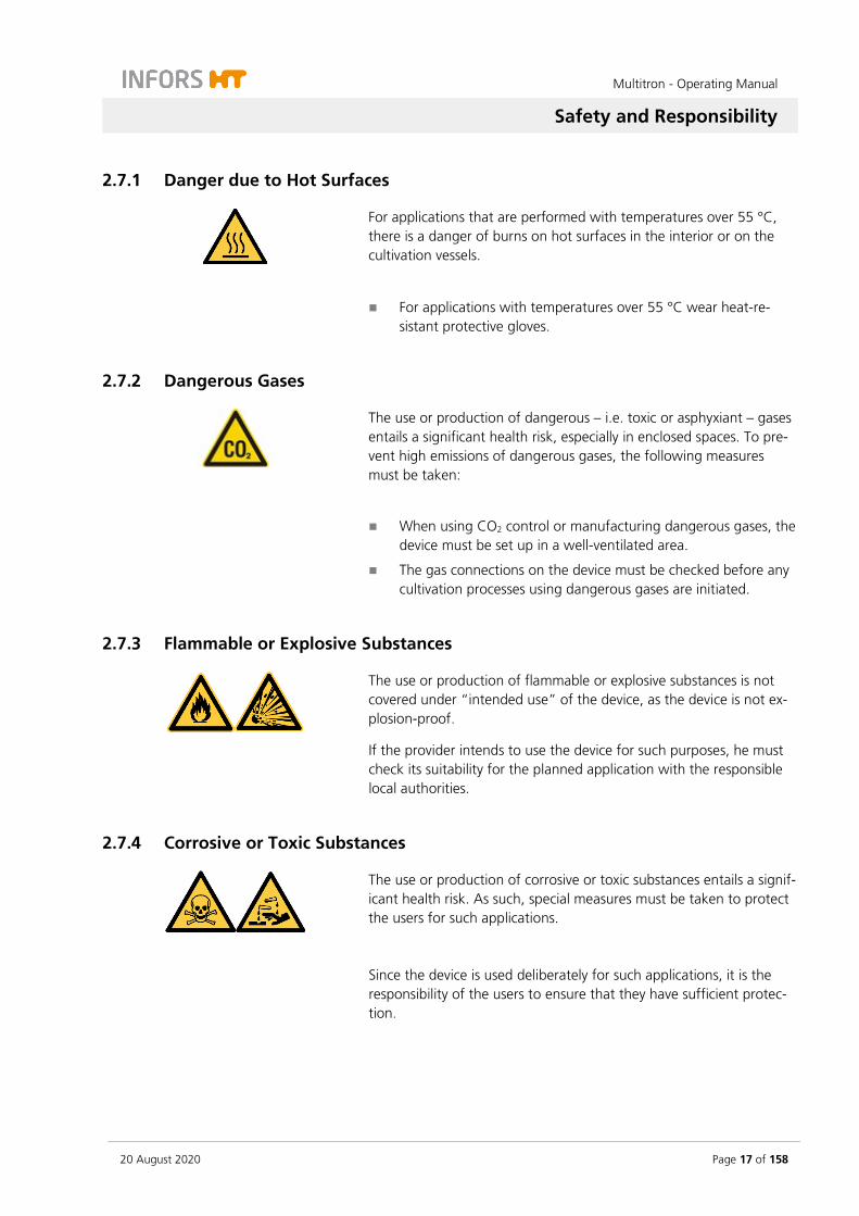
2.7.1 Danger due to Hot Surfaces
For applications that are performed with temperatures over 55 °C, there is a danger of burns on hot surfaces in the interior or on the cultivation vessels.
For applications with temperatures over 55 °C wear heat-re-sistant protective gloves.
2.7.2 Dangerous Gases
The use or production of dangerous – i.e. toxic or asphyxiant – gases entails a significant health risk, especially in enclosed spaces. To pre-vent high emissions of dangerous gases, the following measures must be taken:
When using CO2 control or manufacturing dangerous gases, the device must be set up in a well-ventilated area.
The gas connections on the device must be checked before any cultivation processes using dangerous gases are initiated.
2.7.3 Flammable or Explosive Substances
The use or production of flammable or explosive substances is not covered under “intended use” of the device, as the device is not ex-plosion-proof.
If the provider intends to use the device for such purposes, he must check its suitability for the planned application with the responsible local authorities.
2.7.4 Corrosive or Toxic Substances
The use or production of corrosive or toxic substances entails a signif-icant health risk. As such, special measures must be taken to protect the users for such applications.
Since the device is used deliberately for such applications, it is the responsibility of the users to ensure that they have sufficient protec-tion.
Multitron - Operating Manual
Safety and Responsibility
Page 18 of 158 20 August 2020
2.7.5 Pathogenic Organisms
The device is not approved for cultivation of pathogenic organisms of risk categories 3 and 4. In the context of intended use, it is nonethe-less possible for pathogenic organisms and viruses to be cultivated. Contact with pathogenic organisms bears a significant health risk. Hence, users are responsible for ensuring adequate protection.
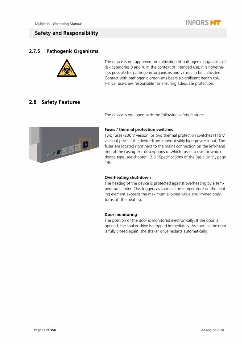
2.8 Safety Features
The device is equipped with the following safety features:
Fuses / thermal protection switches Two fuses (230 V version) or two thermal protection switches (115 V version) protect the device from impermissibly high power input. The fuses are located right next to the mains connection on the left-hand side of the casing. For descriptions of which fuses to use for which device type, see chapter 12.3 "Specifications of the Basic Unit", page 140.
Overheating shut-down The heating of the device is protected against overheating by a tem-perature limiter. This triggers as soon as the temperature on the heat-ing element exceeds the maximum allowed value and immediately turns off the heating.
Door monitoring The position of the door is monitored electronically. If the door is opened, the shaker drive is stopped immediately. As soon as the door is fully closed again, the shaker drive restarts automatically.
Multitron - Operating Manual
Safety and Responsibility
20 August 2020 Page 19 of 158
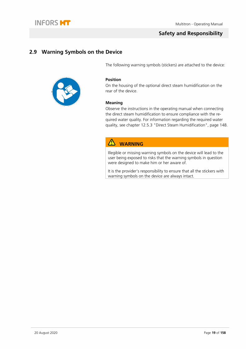
2.9 Warning Symbols on the Device
The following warning symbols (stickers) are attached to the device:
Position On the housing of the optional direct steam humidification on the rear of the device. Meaning Observe the instructions in the operating manual when connecting the direct steam humidification to ensure compliance with the re-quired water quality. For information regarding the required water quality, see chapter 12.5.3 "Direct Steam Humidification", page 148.
WARNING
Illegible or missing warning symbols on the device will lead to the user being exposed to risks that the warning symbols in question were designed to make him or her aware of.
It is the provider’s responsibility to ensure that all the stickers with warning symbols on the device are always intact.

Multitron - Operating Manual
Safety and Responsibility
Page 20 of 158 20 August 2020
2.10 Declaration of Decontamination
When returning the device for repair, disassembly or disposal, it is required for the safety of all parties involved and because of legal provisions that a lawful declaration of decontamination is present.
The following must be observed if this is the case:
The device, the component part or accessory must be entirely decontaminated before sending to the manufacturer
The provider is therefore required to completely and truthfully fill out a declaration of decontamination, and have it signed by the person responsible.
The declaration of decontamination must be affixed on the outer packaging in which the device is sent back.
These forms can be obtained from the licensed dealer or the manufacturer. See address on page 2.
Important notice
If the return shipment is not accompanied by a signed and complete declaration of decontamination or it is not affixed to the outer pack-aging, the shipment will be returned unopened to the sender at their expense (see also T&C).

Multitron - Operating Manual
Setup and Function
20 August 2020 Page 21 of 158
3 Setup and Function
3.1 Setup of the Basic Unit
Exterior
1 Cover (optional)
2 Display and operating elements
3 Door handle
4 Door with window (opens downwards)
5 Discharge outlet
6 Casing
1
2
3 4
6
5
Multitron - Operating Manual
Setup and Function
Page 22 of 158 20 August 2020
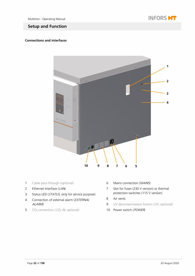
Connections and interfaces
1 Cable pass-through (optional)
2 Ethernet Interface (LAN)
3 Status LED (STATUS, only for service purpose)
4 Connection of external alarm (EXTERNAL ALARM)
5 CO2 connection (CO2 IN, optional)
6 Mains connection (MAINS)
7 Slot for fuses (230 V version) or thermal protection switches (115 V version)
8 Air vents
9 UV decontamination button (UV, optional)
10 Power switch (POWER)
1
3
5 6 9 10
4
8
2
7
Multitron - Operating Manual
Setup and Function
20 August 2020 Page 23 of 158
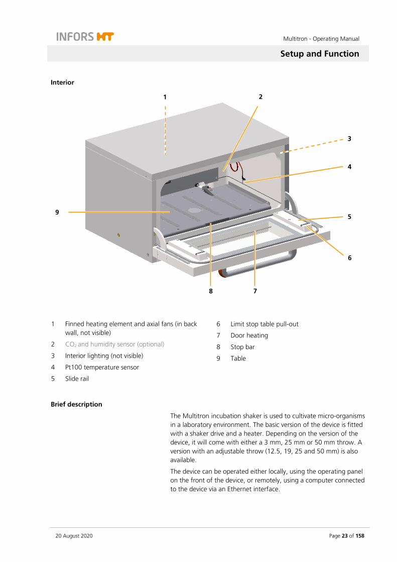
Interior
1 Finned heating element and axial fans (in back wall, not visible)
2 CO2 and humidity sensor (optional)
3 Interior lighting (not visible)
4 Pt100 temperature sensor
5 Slide rail
6 Limit stop table pull-out
7 Door heating
8 Stop bar
9 Table
Brief description
The Multitron incubation shaker is used to cultivate micro-organisms in a laboratory environment. The basic version of the device is fitted with a shaker drive and a heater. Depending on the version of the device, it will come with either a 3 mm, 25 mm or 50 mm throw. A version with an adjustable throw (12.5, 19, 25 and 50 mm) is also available.
The device can be operated either locally, using the operating panel on the front of the device, or remotely, using a computer connected to the device via an Ethernet interface.
1
3
5
6
7 8
9
4
2

Multitron - Operating Manual
Setup and Function
Page 24 of 158 20 August 2020
Stacking devices
If necessary, up to three units can be stacked to save space. The de-vices can also be stacked subsequently but stacking must be per-formed by the manufacturer’s qualified expert personnel or persons authorised by the manufacturer. If stacked devices are operated, you have to keep in mind that the maximum permissible rotation speed is limited for the top units in the stack. For a detailed description of the technical data and possible maxi-mum rotation speeds of stacked devices, see chapter 12.4.1 "Rota-tion Speed Parameter (Shaker Drive)", page 144.
Overview of options
To be able to adapt the device to different application situations, the following options are available:
Option Additional information
Internal or external cooling see chapter 4.1, page 35
Direct steam humidification see chapter 4.2, page 39
Pressure elimination unit for direct steam humidification
see chapter 4.3, page 42
CO2 control see chapter 4.4, page 48
UV decontamination see chapter 4.5, page 50
Removable shelf see chapter 4.6, page 51
LED lighting see chapter 4.7, page 52
Darkening see chapter 4.8, page 53
Analog output see chapter 4.9, page 53
Cable pass-through see chapter 4.10, page 54
Antimicrobial coating see chapter 4.11, page 56

Multitron - Operating Manual
Setup and Function
20 August 2020 Page 25 of 158
3.2 Basic Functions
The standard features of the device include the shaking function (pa-rameter RPM) and temperature control (parameter Temp).
3.2.1 Standard Function Shaking
1 Counterweight
2 Tray ejection
3 Drive hub
The shaking table moves in circles. It is driven by an electric motor, which is connected to the device’s flywheel by a drive belt. To pre-vent injuries and facilitate loading and unloading, the drive is switched off automatically as soon as the door is opened. The counterweight used to balance the mass is fitted under the table. Depending on the design, the deflection of the circular movement is either 3, 25 or 50 mm or 12,5, 19, 25 or 50 mm for devices with an adjustable throw. The table moves in clockwise circles.
1
2
2
3

Multitron - Operating Manual
Setup and Function
Page 26 of 158 20 August 2020
Table
The table is used to hold the 85 x 47 cm (type M) tray, various ver-sions of which are available. Bars on the sides, two stops and two tapered plugs ensure that the tray is positioned correctly.
The table is connected to the drive hub by means of three hexalobu-lar socket head cap (Torx) screws. To clean the base tray, the three screws can be unscrewed and the table can be lifted 30° to allow ac-cess.
Depending on the throw of the device, the table varies as follows:
Table with 25 and 50 mm throw:
1 Drive hub
2 Limit stop
3 Tray ejection
4 Tapered plug
Table with 3 mm throw:
1 Drive hub
2 Limit stop
3 Knurled screw
4 Tapered plug
1 3 2 4
1 3 4
2
Multitron - Operating Manual
Setup and Function
20 August 2020 Page 27 of 158
Adjustable throw
If the device features an adjustable throw, there are four possible po-sitions for the eccentric throw:
12.5 mm
19 mm
25 mm
50 mm
The counterweights are also adjustable to reduce vibrations during operation.
INFORMATION
The throw may only be adjusted by personnel that has received appropriate training and authorisations. If in doubt, contact IN-FORS HT (see contact details on page 2).
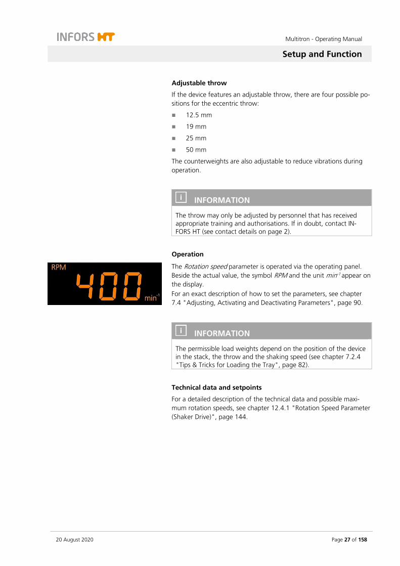
Operation
The Rotation speed parameter is operated via the operating panel. Beside the actual value, the symbol RPM and the unit min-1 appear on the display. For an exact description of how to set the parameters, see chapter 7.4 "Adjusting, Activating and Deactivating Parameters", page 90.
INFORMATION
The permissible load weights depend on the position of the device in the stack, the throw and the shaking speed (see chapter 7.2.4 "Tips & Tricks for Loading the Tray", page 82).
Technical data and setpoints
For a detailed description of the technical data and possible maxi-mum rotation speeds, see chapter 12.4.1 "Rotation Speed Parameter (Shaker Drive)", page 144.
Multitron - Operating Manual
Setup and Function
Page 28 of 158 20 August 2020
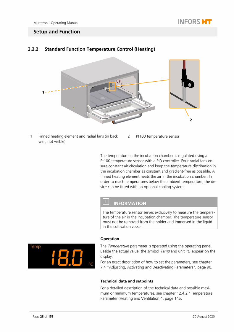
3.2.2 Standard Function Temperature Control (Heating)
1 Finned heating element and radial fans (in back wall, not visible)
2 Pt100 temperature sensor
The temperature in the incubation chamber is regulated using a Pt100 temperature sensor with a PID controller. Four radial fans en-sure constant air circulation and keep the temperature distribution in the incubation chamber as constant and gradient-free as possible. A finned heating element heats the air in the incubation chamber. In order to reach temperatures below the ambient temperature, the de-vice can be fitted with an optional cooling system.
INFORMATION
The temperature sensor serves exclusively to measure the tempera-ture of the air in the incubation chamber. The temperature sensor must not be removed from the holder and immersed in the liquid in the cultivation vessel.
Operation
The Temperature parameter is operated using the operating panel. Beside the actual value, the symbol Temp and unit °C appear on the display. For an exact description of how to set the parameters, see chapter 7.4 "Adjusting, Activating and Deactivating Parameters", page 90.
Technical data and setpoints
For a detailed description of the technical data and possible maxi-mum or minimum temperatures, see chapter 12.4.2 "Temperature Parameter (Heating and Ventilation)", page 145.
1
2
Multitron - Operating Manual
Setup and Function
20 August 2020 Page 29 of 158
3.3 Connections and Interfaces
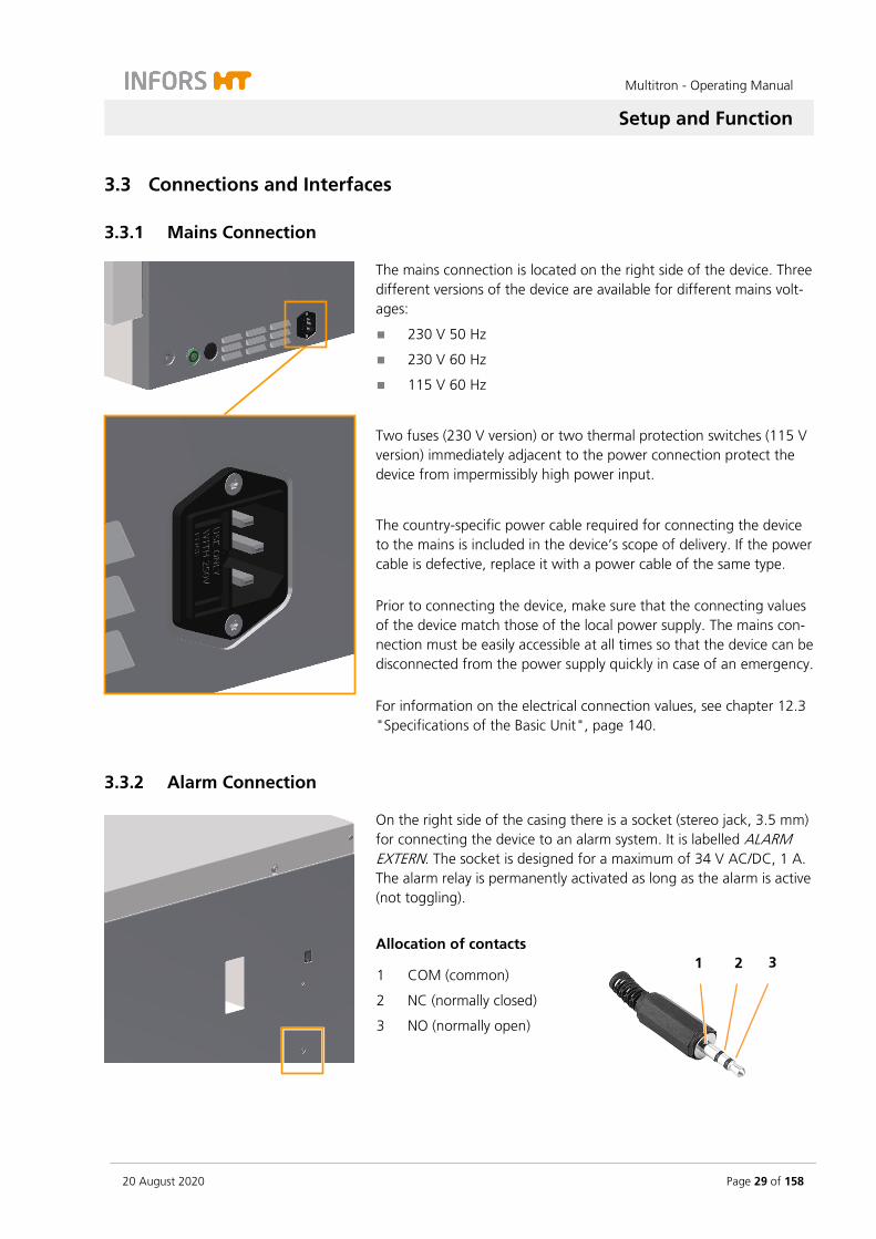
3.3.1 Mains Connection
The mains connection is located on the right side of the device. Three different versions of the device are available for different mains volt-ages:
230 V 50 Hz
230 V 60 Hz
115 V 60 Hz
Two fuses (230 V version) or two thermal protection switches (115 V version) immediately adjacent to the power connection protect the device from impermissibly high power input.
The country-specific power cable required for connecting the device to the mains is included in the device’s scope of delivery. If the power cable is defective, replace it with a power cable of the same type. Prior to connecting the device, make sure that the connecting values of the device match those of the local power supply. The mains con-nection must be easily accessible at all times so that the device can be disconnected from the power supply quickly in case of an emergency. For information on the electrical connection values, see chapter 12.3 "Specifications of the Basic Unit", page 140.
3.3.2 Alarm Connection
On the right side of the casing there is a socket (stereo jack, 3.5 mm) for connecting the device to an alarm system. It is labelled ALARM EXTERN. The socket is designed for a maximum of 34 V AC/DC, 1 A. The alarm relay is permanently activated as long as the alarm is active (not toggling).
Allocation of contacts
1 COM (common)
2 NC (normally closed)
3 NO (normally open)
1 3 2

Multitron - Operating Manual
Setup and Function
Page 30 of 158 20 August 2020
3.3.3 Ethernet Interface
The device is provided with an Ethernet interface (RJ45 socket). The socket is located on the right side of the device. The Ethernet interface can be used to integrate the device into a net-work and thus control it using a remote computer. To control the de-vice using a remote computer, eve® the bioprocess platform software is required. If the device is to be controlled using other software, a special communication protocol is required. For further information contact INFORS HT. The Ethernet interface makes it possible to send and receive data. For example, setpoints can be sent to the device or values measured by the sensors can be sent to eve®. If the device is connected to eve® via Ethernet or if the device is controlled using eve®, this is displayed on the operating panel. For more information on the use of the Ethernet interface, see chap-ter 7.6 "Using eve® to Operate the Device", page 109.
3.4 Openings
3.4.1 Discharge Outlet
The opening for discharging leaked liquids, detergents or condensa-tion that has been collected is located at the bottom, on the left hand side of the casing, close to the centre. The opening is sealed with a yellow plug. A hose nozzle (¼ inch) for connecting a hose (Ø 10 mm) is provided.
INFORMATION
In case of large fill volumes, we recommend installing the dis-charge hose to avoid the bearings coming into contact with liquid if a flask breaks.
If safety requirements must be met, e.g. when working with ge-netically modified organisms, the discharge hose must lead to a suitable, sealed receptacle. This can be, for example, an empty chemical container that is sealed with foil.
Multitron - Operating Manual
Setup and Function
20 August 2020 Page 31 of 158
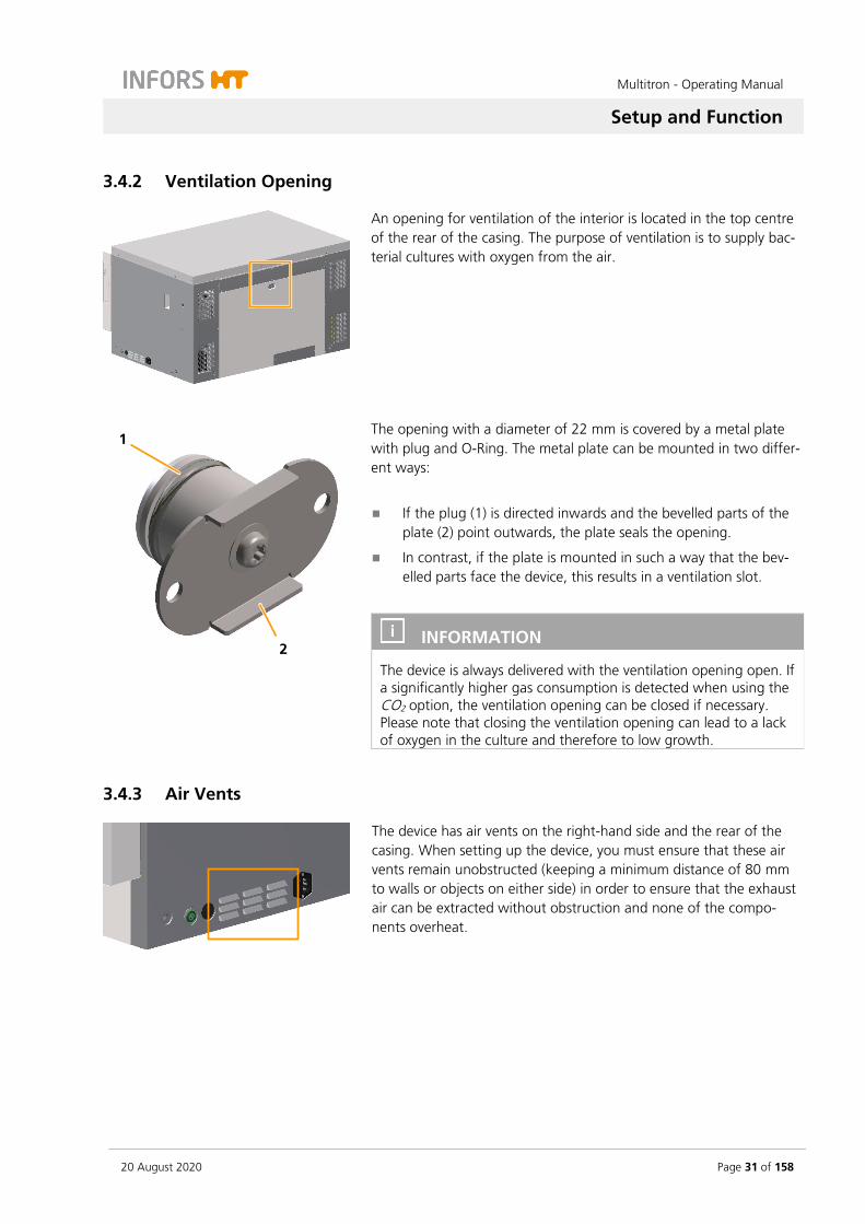
3.4.2 Ventilation Opening
An opening for ventilation of the interior is located in the top centre of the rear of the casing. The purpose of ventilation is to supply bac-terial cultures with oxygen from the air.
The opening with a diameter of 22 mm is covered by a metal plate with plug and O-Ring. The metal plate can be mounted in two differ-ent ways:
If the plug (1) is directed inwards and the bevelled parts of the plate (2) point outwards, the plate seals the opening.
In contrast, if the plate is mounted in such a way that the bev-elled parts face the device, this results in a ventilation slot.
INFORMATION
The device is always delivered with the ventilation opening open. If a significantly higher gas consumption is detected when using the CO2 option, the ventilation opening can be closed if necessary. Please note that closing the ventilation opening can lead to a lack of oxygen in the culture and therefore to low growth.
3.4.3 Air Vents
The device has air vents on the right-hand side and the rear of the casing. When setting up the device, you must ensure that these air vents remain unobstructed (keeping a minimum distance of 80 mm to walls or objects on either side) in order to ensure that the exhaust air can be extracted without obstruction and none of the compo-nents overheat.
1
2

Multitron - Operating Manual
Setup and Function
Page 32 of 158 20 August 2020
3.5 Interior Lighting
The device features two LED spots to illuminate the incubation cham-ber. These are located in the door area on the inside of the casing. The interior lighting is switched on automatically as soon as a button is pressed or the door is opened. After 20 seconds without input or 20 seconds after closing the door, the lighting switches off again au-tomatically. In the settings menu (OPTION key) the interior lighting can be com-pletely deactivated if necessary.
3.6 Frames
The incubation shaker is available with the following frames:
Low base, 13 cm
Individual units and stacked devices can be fitted with a 13 cm base. The base has an adjustable foot that can be used to level the device.
Multitron - Operating Manual
Setup and Function
20 August 2020 Page 33 of 158
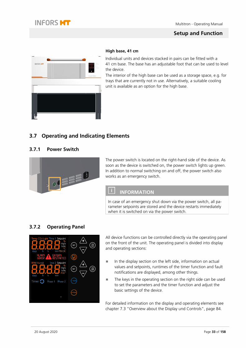
High base, 41 cm
Individual units and devices stacked in pairs can be fitted with a 41 cm base. The base has an adjustable foot that can be used to level the device. The interior of the high base can be used as a storage space, e.g. for trays that are currently not in use. Alternatively, a suitable cooling unit is available as an option for the high base.
3.7 Operating and Indicating Elements
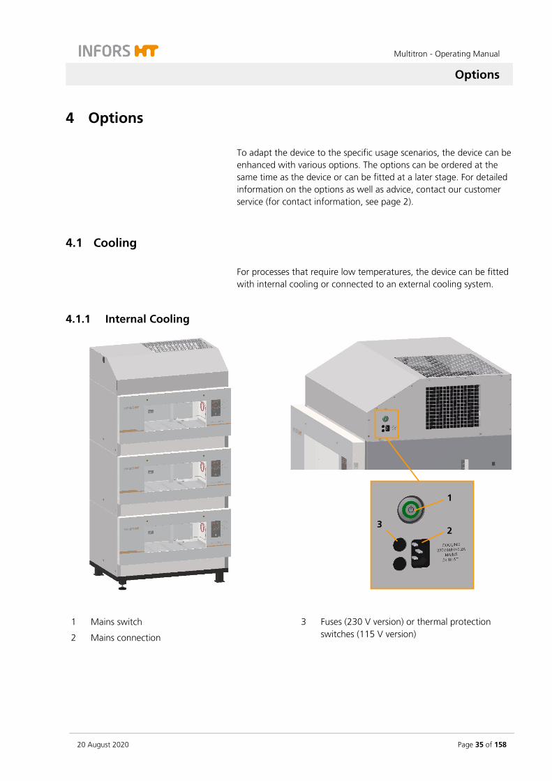
3.7.1 Power Switch
The power switch is located on the right-hand side of the device. As soon as the device is switched on, the power switch lights up green. In addition to normal switching on and off, the power switch also works as an emergency switch.
INFORMATION
In case of an emergency shut down via the power switch, all pa-rameter setpoints are stored and the device restarts immediately when it is switched on via the power switch.
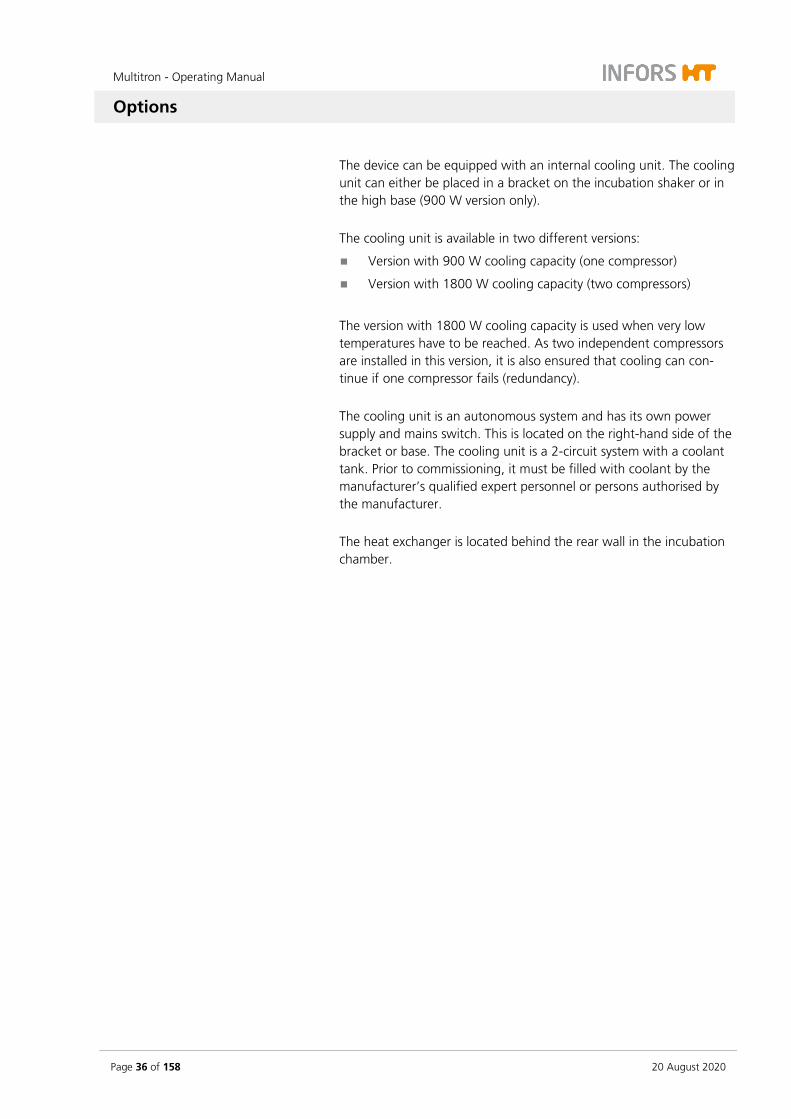
3.7.2 Operating Panel
All device functions can be controlled directly via the operating panel on the front of the unit. The operating panel is divided into display and operating sections:
In the display section on the left side, information on actual values and setpoints, runtimes of the timer function and fault notifications are displayed, among other things.
The keys in the operating section on the right side can be used to set the parameters and the timer function and adjust the basic settings of the device.
For detailed information on the display and operating elements see chapter 7.3 "Overview about the Display und Controls", page 84.

Multitron - Operating Manual
Setup and Function
Page 34 of 158 20 August 2020
3.8 Markings on the Device
3.8.1 Identification Plate
The identification plates for identifying the device are located on the right side of the casing, directly above the mains connection and on the front of the door. For information on the data provided on the identification plate see chapter 1.3 "Device Identification (Standard Identification Plate)", page 9.
3.8.2 Identification of the Throw
At the back wall inside the incubation chamber, there is a sticker that identifies the throw of the device.
Multitron - Operating Manual
Options
20 August 2020 Page 35 of 158
4 Options
To adapt the device to the specific usage scenarios, the device can be enhanced with various options. The options can be ordered at the same time as the device or can be fitted at a later stage. For detailed information on the options as well as advice, contact our customer service (for contact information, see page 2).
4.1 Cooling
For processes that require low temperatures, the device can be fitted with internal cooling or connected to an external cooling system.
4.1.1 Internal Cooling
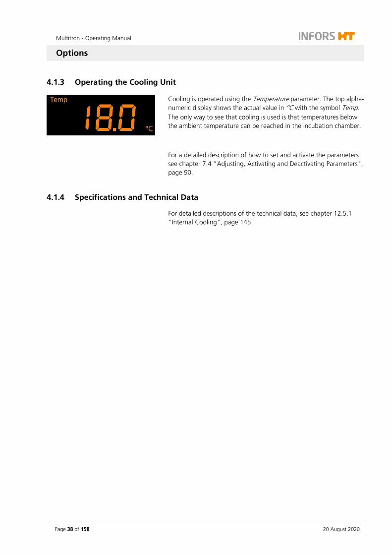
1 Mains switch
2 Mains connection
3 Fuses (230 V version) or thermal protection switches (115 V version)
3
1
2
Multitron - Operating Manual
Options
Page 36 of 158 20 August 2020
The device can be equipped with an internal cooling unit. The cooling unit can either be placed in a bracket on the incubation shaker or in the high base (900 W version only). The cooling unit is available in two different versions:
Version with 900 W cooling capacity (one compressor)
Version with 1800 W cooling capacity (two compressors)
The version with 1800 W cooling capacity is used when very low temperatures have to be reached. As two independent compressors are installed in this version, it is also ensured that cooling can con-tinue if one compressor fails (redundancy). The cooling unit is an autonomous system and has its own power supply and mains switch. This is located on the right-hand side of the bracket or base. The cooling unit is a 2-circuit system with a coolant tank. Prior to commissioning, it must be filled with coolant by the manufacturer’s qualified expert personnel or persons authorised by the manufacturer. The heat exchanger is located behind the rear wall in the incubation chamber.

Multitron - Operating Manual
Options
20 August 2020 Page 37 of 158
4.1.2 External Cooling
Setup and function
If you are planning to connect the device to an external cooling sys-tem, a cooling register and a control valve are installed. A control valve opens when necessary to allow cooling liquid to flow through the cooling register. Temperatures are measured using the Pt100 sen-sor which is installed by default.
Connection conditions
1 Cooling medium inlet 2 Cooling medium outlet
The connections for an external cooling system are on the top of the device. The connections are labelled COOLANT IN (inlet) and COOL-ANT OUT (outlet). If two or three units with external cooling are stacked, the lines are connected internally and only the top unit has connections on the top.
The connection pressure at the inlet of the cooling medium may be up to 4 bar, the outlet should be depressurised. The external diame-ter of the hose nozzles is 10 mm.
ATTENTION
The installed valve regulates the temperature by closing and open-ing the cycle. Hence it can be necessary to install a bypass from the inlet to the outlet to protect the circulation pump against dam-age.
1 2
Multitron - Operating Manual
Options
Page 38 of 158 20 August 2020
4.1.3 Operating the Cooling Unit
Cooling is operated using the Temperature parameter. The top alpha-numeric display shows the actual value in °C with the symbol Temp. The only way to see that cooling is used is that temperatures below the ambient temperature can be reached in the incubation chamber.
For a detailed description of how to set and activate the parameters see chapter 7.4 "Adjusting, Activating and Deactivating Parameters", page 90.
4.1.4 Specifications and Technical Data
For detailed descriptions of the technical data, see chapter 12.5.1 "Internal Cooling", page 145.
Multitron - Operating Manual
Options
20 August 2020 Page 39 of 158
4.2 Direct Steam Humidification
Part of the medium can evaporate, in particular in case of small vol-umes of work (e.g. when using microtitre and deep well plates) and long cultivation processes. To reduce evaporation, the device can be fitted with a direct steam humidification. This regulates the humidity in the incubation chamber to a defined setpoint and thus ensures a consistent culture volume.
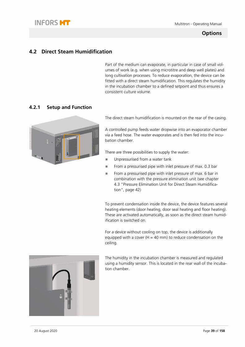
4.2.1 Setup and Function
The direct steam humidification is mounted on the rear of the casing. A controlled pump feeds water dropwise into an evaporator chamber via a feed hose. The water evaporates and is then fed into the incu-bation chamber. There are three possibilities to supply the water:
Unpressurised from a water tank
From a pressurised pipe with inlet pressure of max. 0.3 bar
From a pressurised pipe with inlet pressure of max. 6 bar in combination with the pressure elimination unit (see chapter 4.3 "Pressure Elimination Unit for Direct Steam Humidifica-tion", page 42)
To prevent condensation inside the device, the device features several heating elements (door heating, door seal heating and floor heating). These are activated automatically, as soon as the direct steam humid-ification is switched on. For a device without cooling on top, the device is additionally equipped with a cover (H = 40 mm) to reduce condensation on the ceiling.
The humidity in the incubation chamber is measured and regulated using a humidity sensor. This is located in the rear wall of the incuba-tion chamber.
Multitron - Operating Manual
Options
Page 40 of 158 20 August 2020
Observe the following points when using the direct steam humidifica-tion:
The direct steam humidification only works actively in one direc-tion. It only humidifies; it does not dehumidify.
The direct steam humidification is optimised for operation at temperatures up to 40 °C.
If the direct steam humidification is used in combination with the LED illumination, the heat radiating from the LEDs can result in the desired humidity not being reached. In addition, there can be significant condensation in the incubation chamber.
The Temperature parameter must be activated.
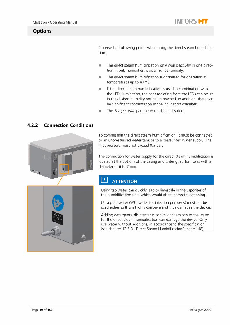
4.2.2 Connection Conditions
To commission the direct steam humidification, it must be connected to an unpressurised water tank or to a pressurised water supply. The inlet pressure must not exceed 0.3 bar. The connection for water supply for the direct steam humidification is located at the bottom of the casing and is designed for hoses with a diameter of 6 to 7 mm.
ATTENTION
Using tap water can quickly lead to limescale in the vaporiser of the humidification unit, which would affect correct functioning.
Ultra pure water (WFI, water for injection purposes) must not be used either as this is highly corrosive and thus damages the device.
Adding detergents, disinfectants or similar chemicals to the water for the direct steam humidification can damage the device. Only use water without additions, in accordance to the specification (see chapter 12.5.3 "Direct Steam Humidification", page 148).
Multitron - Operating Manual
Options
20 August 2020 Page 41 of 158
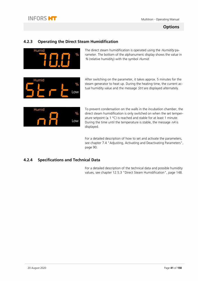
4.2.3 Operating the Direct Steam Humidification
The direct steam humidification is operated using the Humidity pa-rameter. The bottom of the alphanumeric display shows the value in % (relative humidity) with the symbol Humid.
After switching on the parameter, it takes approx. 5 minutes for the steam generator to heat up. During the heating time, the current ac-tual humidity value and the message Strt are displayed alternately.
To prevent condensation on the walls in the incubation chamber, the direct steam humidification is only switched on when the set temper-ature setpoint (± 1 °C) is reached and stable for at least 1 minute. During the time until the temperature is stable, the message nA is displayed.
For a detailed description of how to set and activate the parameters, see chapter 7.4 "Adjusting, Activating and Deactivating Parameters", page 90.
4.2.4 Specifications and Technical Data
For a detailed description of the technical data and possible humidity values, see chapter 12.5.3 "Direct Steam Humidification", page 148.

Multitron - Operating Manual
Options
Page 42 of 158 20 August 2020
4.3 Pressure Elimination Unit for Direct Steam Humidification
The pressure elimination unit is used to connect the optional direct steam humidification to a pressurized water line (e.g. VE water line) with a pressure of up to 6 bar.
4.3.1 Setup and Function
A Water inlet line steam generators
B Mains connection level sensor
C Solenoid valve
D Connection pressurized water line
E Stainless steel vessel
F Valve
G Float
H One-way filter for pressure compensation
I Level sensor
A
D
E
F
G
H
I
B
C

Multitron - Operating Manual
Options
20 August 2020 Page 43 of 158
The pressure elimination unit consists mainly of a stainless steel vessel (E), which is filled with water via the operator's pressurized water line (D). If the level in the vessel decreases, the float (G) is lowered and thus opens the valve (F). This allows water to flow into the vessel. The float is thereby lifted again and closes the valve as soon as the maxi-mum level is reached. The pressureless water in the vessel is then pumped by the pump of the direct steam humidification into the evaporator chamber of the steam generator.
A level sensor (I) is mounted as protection against overflow if the float valve does not close correctly. This detects an excessively high water level and closes a solenoid valve (C) in the pressurized water line.
The pressure elimination unit is suspended in a mounting bracket on the back of the shaker. The vessel can thus be easily removed for cleaning and sterilization in the autoclave. The hose lines to the steam generators are routed at the rear of the unit and are fastened with hose brackets. Up to three steam genera-tors can be connected to one pressure elimination unit via T-pieces.
4.3.2 Cleaning the Pressure Elimination Unit
To clean the interior of the vessel, the pressure elimination unit can be dismounted. Proceed as follows:
1. Remove the clamp to the operator‘s water supply line (B).
2. Disconnect the rapid coupling of the water supply line to the steam generators (A).
3. Lift the pressure elimination unit out of the mounting bracket and place it on a flat surface.
A
B

Multitron - Operating Manual
Options
Page 44 of 158 20 August 2020
4. Remove the level sensor:
a) Disconnect the mains cable of the level sensor.
b) Disconnect the connection cable on the solenoid valve.
c) Loosen the wing nut of the clamp.
d) Open and remove the clamp.
e) Remove the level sensor.
5. Remove the lid. To do so, loosen and unscrew the four cross-head screws.
6. Carefully lift the lid upwards.
7. Clean the vessel and other components as required. For infor-mation on correct cleaning, see the information below.
Detergents
For cleaning use a mild detergent, e.g. dishwashing liquid or neutral cleaning agent.

Multitron - Operating Manual
Options
20 August 2020 Page 45 of 158
ATTENTION
Aggressive cleaning agents, solvents and abrasive cleaning utensils (hard sponges, brushes) can scratch surfaces, damage the equip-ment and impair its function. In addition, do not use cleaning agents containing chlorine, as stainless steel is not resistant to substances containing chlorine.
Disinfectants
Only use quaternary ammonium compounds for wipe-down disinfec-tion. As a tried as tested disinfectant, we recommend Fermacidal D2. An alcohol-based disinfectant (e.g. 70 % ethanol) can be used to rinse the system.
Materials
If other cleaning or disinfecting agents should be used, it is the re-sponsibility of the operator to check whether the agent is compatible with the materials used. The following table gives an overview of the materials of the components of the pressure elimination unit.
Components Material
Vessel, lid, pipes, level sensor, float valve, mount-ing bracket
Stainless steal
Rapid couplings Polysulfone
Flat gaskets EPDM
Pressure hoses Silicone (VMQ)
4.3.3 Autoclaving the Pressure Elimination Unit
After cleaning, the pressure elimination unit can be sterilized in an autoclave if required. Proceed as follows:
CAUTION
If there is no pressure compensation, overpressure may occur in the vessel. Therefore always keep the hose piece with the filter open.
ATTENTION
If the vessel is autoclaved empty, no steam can build up. The steri-lization success is not guaranteed.
Ensure that there is approx. 40 ml water in the vessel.
Multitron - Operating Manual
Options
Page 46 of 158 20 August 2020
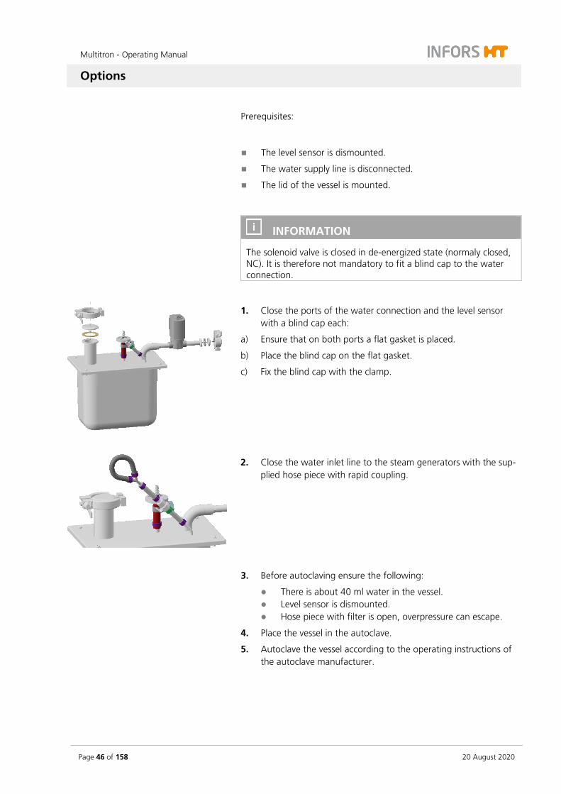
Prerequisites:
The level sensor is dismounted.
The water supply line is disconnected.
The lid of the vessel is mounted.
INFORMATION
The solenoid valve is closed in de-energized state (normaly closed, NC). It is therefore not mandatory to fit a blind cap to the water connection.
1. Close the ports of the water connection and the level sensor with a blind cap each:
a) Ensure that on both ports a flat gasket is placed.
b) Place the blind cap on the flat gasket.
c) Fix the blind cap with the clamp.
2. Close the water inlet line to the steam generators with the sup-plied hose piece with rapid coupling.
3. Before autoclaving ensure the following:
There is about 40 ml water in the vessel. Level sensor is dismounted. Hose piece with filter is open, overpressure can escape.
4. Place the vessel in the autoclave.
5. Autoclave the vessel according to the operating instructions of the autoclave manufacturer.
Multitron - Operating Manual
Options
20 August 2020 Page 47 of 158
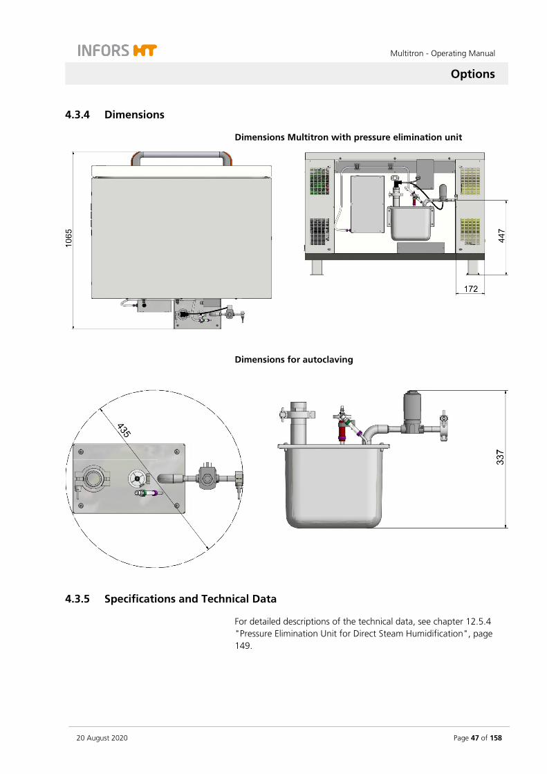
4.3.4 Dimensions
Dimensions Multitron with pressure elimination unit
Dimensions for autoclaving
4.3.5 Specifications and Technical Data
For detailed descriptions of the technical data, see chapter 12.5.4 "Pressure Elimination Unit for Direct Steam Humidification", page 149.

Multitron - Operating Manual
Options
Page 48 of 158 20 August 2020
4.4 CO2 Control
The optional CO2 control makes it possible to enrich the atmosphere in the incubation chamber by 0 to 20 % CO2. The CO2 control option is particularly suited to cultivation of mammalian cells and algae be-cause the CO2 ensures that the pH value in the culture solution is sta-ble.
CAUTION
During normal operation, small amounts of CO2 are constantly dis-sipated into the environment. Leaking CO2 can lead to discomfort, loss of consciousness or even death by suffocation, especially in small rooms.
– The operator is obliged to install a monitoring system which permanently monitors and analyses the CO2 concentration in the room.
– If you are using the CO2 control, only operate the device in well-ventilated areas.
– Comply with local health and safety regulations and regula-tions regarding the use of CO2 and its limits.
– Regularly check the gas pipelines for leaks.
INFORMATION
Opening the ventilation opening at the back of the device can lead to significantly higher gas consumption. We therefore recommend leaving the ventilation opening closed when using the CO2 control option.
4.4.1 Setup and Function
CO2 supply is controlled using a controlled valve. Inflow of CO2 must be ensured using external supply where the pressure can be regu-lated. On the right side of the casing, there is a hose nozzle for a hose with a diameter of 3 to 4 mm to connect the supply.

Multitron - Operating Manual
Options
20 August 2020 Page 49 of 158
The CO2 content in the incubation chamber is measured and regu-lated using a CO2 sensor. This is mounted on the right side of the back wall of the incubation chamber.
4.4.2 Connection Conditions
The in-house gas supply and connecting hose must meet the follow-ing requirements:
Gas supply
Constant input pressure not exceeding 0.5 bar (± 0.1)
Only use clean, dry, oil and dust free gas.
Hoses
Use only pressure-resistant and intact hoses.
The hose must have an appropriate diameter; an adapter may be used, if necessary.
Secure hoses using appropriate clamps.
4.4.3 Operating the CO2 Control
The CO2 control is operated using the CO2 parameter. The top alpha-numeric display shows the actual value in % with the symbol CO2. To prevent large amounts of CO2 from escaping, the CO2 control is de-activated automatically while the door is open.
For a detailed description of how to set and activate the parameters, see chapter 7.4 "Adjusting, Activating and Deactivating Parameters", page 90.
4.4.4 Specifications and Technical Data
For a detailed description of the technical data and possible CO2 val-ues, see chapter 12.5.5 "CO2 Control", page 150.

Multitron - Operating Manual
Options
Page 50 of 158 20 August 2020
4.5 UV Decontamination
4.5.1 Setup and Function
The optional UV decontamination is used to kill microorganisms in the air in the incubation chamber. The option consists of two UV de-contamination lamps on the rear wall of the housing. These emit high-energy UV radiation of 253.7 nm. The air, which is drawn in by the axial fans, flows past the UV decontamination lamps. The micro-organisms contained in the air flow are killed by the UV radiation.
4.5.2 Operating the UV Decontamination
The UV decontamination is controlled using a pushbutton on the right side of the device. The pushbutton lights up when the UV de-contamination is active. Observe the following points when using the UV decontamination:
The Temperature parameter must be activated.
For safety reasons, the UV decontamination lamps are switched off when the door is opened.
4.5.3 Specifications and Technical Data
For detailed descriptions of the technical data regarding the UV de-contamination, see chapter 12.5.6 "UV Decontamination", page 151.
Multitron - Operating Manual
Options
20 August 2020 Page 51 of 158
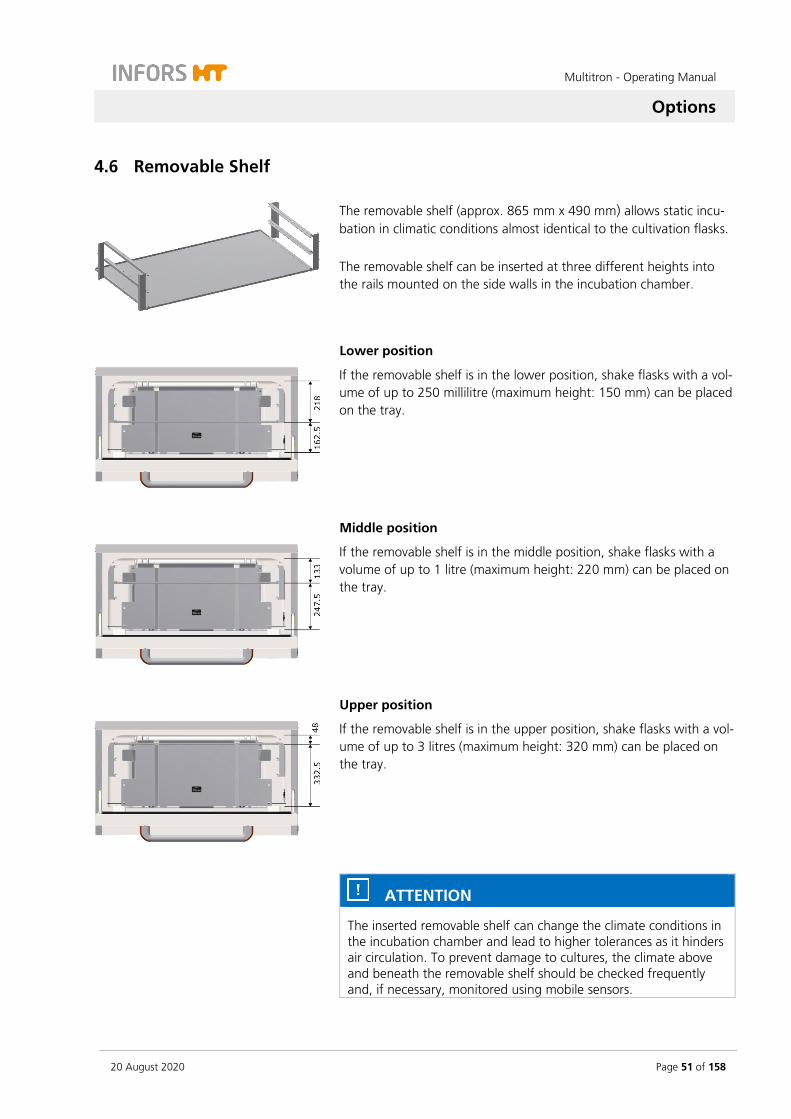
4.6 Removable Shelf
The removable shelf (approx. 865 mm x 490 mm) allows static incu-bation in climatic conditions almost identical to the cultivation flasks. The removable shelf can be inserted at three different heights into the rails mounted on the side walls in the incubation chamber.
Lower position
If the removable shelf is in the lower position, shake flasks with a vol-ume of up to 250 millilitre (maximum height: 150 mm) can be placed on the tray.
Middle position
If the removable shelf is in the middle position, shake flasks with a volume of up to 1 litre (maximum height: 220 mm) can be placed on the tray.
Upper position
If the removable shelf is in the upper position, shake flasks with a vol-ume of up to 3 litres (maximum height: 320 mm) can be placed on the tray.
ATTENTION
The inserted removable shelf can change the climate conditions in the incubation chamber and lead to higher tolerances as it hinders air circulation. To prevent damage to cultures, the climate above and beneath the removable shelf should be checked frequently and, if necessary, monitored using mobile sensors.
Multitron - Operating Manual
Options
Page 52 of 158 20 August 2020
4.7 LED Lighting
The device can be equipped with a LED lighting option. This illumi-nates the surface of the table at an adjustable light intensity. For ex-ample, the LED lighting option can be used to cultivate phototrophic cells.
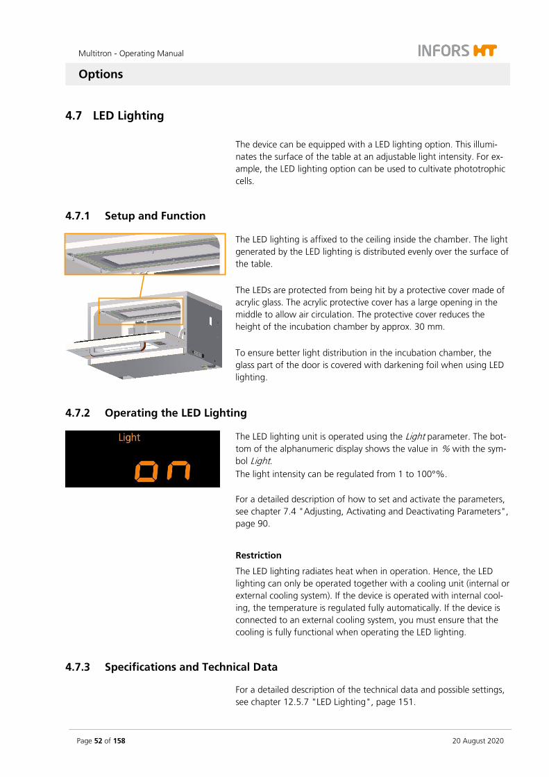
4.7.1 Setup and Function
The LED lighting is affixed to the ceiling inside the chamber. The light generated by the LED lighting is distributed evenly over the surface of the table. The LEDs are protected from being hit by a protective cover made of acrylic glass. The acrylic protective cover has a large opening in the middle to allow air circulation. The protective cover reduces the height of the incubation chamber by approx. 30 mm. To ensure better light distribution in the incubation chamber, the glass part of the door is covered with darkening foil when using LED lighting.
4.7.2 Operating the LED Lighting
The LED lighting unit is operated using the Light parameter. The bot-tom of the alphanumeric display shows the value in % with the sym-bol Light. The light intensity can be regulated from 1 to 100°%.
For a detailed description of how to set and activate the parameters, see chapter 7.4 "Adjusting, Activating and Deactivating Parameters", page 90.
Restriction
The LED lighting radiates heat when in operation. Hence, the LED lighting can only be operated together with a cooling unit (internal or external cooling system). If the device is operated with internal cool-ing, the temperature is regulated fully automatically. If the device is connected to an external cooling system, you must ensure that the cooling is fully functional when operating the LED lighting.
4.7.3 Specifications and Technical Data
For a detailed description of the technical data and possible settings, see chapter 12.5.7 "LED Lighting", page 151.

Multitron - Operating Manual
Options
20 August 2020 Page 53 of 158
4.8 Darkening
The glass panel of the door can be covered with white adhesive film on the inside. This is used for darkening as well as to ensure better light distribution in the incubation chamber when using LED lighting.
4.9 Analog Output
4.9.1 Setup and Function
The device can optionally be equipped with an analog output mod-ule. This provides 8 channels via which setpoints and actual values can be transferred to external devices. The output module is located at the back of the device in its own cas-ing. The signal range corresponds to 4 up to 20 mA with a precision of ± 0.05 mA.
The operator must pre-assemble and connect the cable. To connect the cable, the lid of the casing can be removed by loosening the four hexalobular screws (M4x6). The cable is guided out of the casing us-ing a cable gland. This protects the cable as well as the output mod-ule from mechanical influences and humidity.
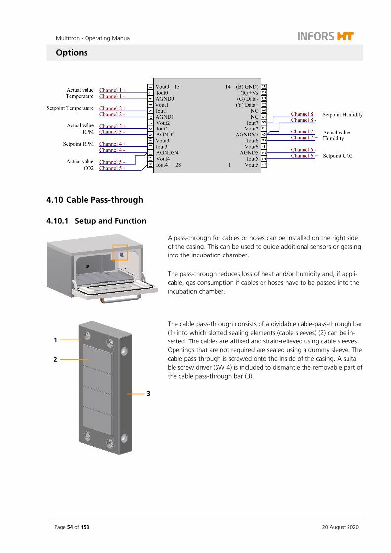
4.9.2 Connection Assignment
The connections of the output module are assigned as follows:
Chan-nel
Connection Function Signal range
1 Iout0 / AGND0 Actual temperature 0 °C to 100 °C = 4 mA to 20 mA
2 Iout1 / AGND1 Temperature setpoint
3 Iout2 / AGND2 Actual speed 25/50 mm and adjustable throw: 0 min-1 to 500 min-1 = 4 mA to 20 mA 3 mm throw: 0 min-1 to 1000 min-1 = 4 mA to 20 mA
4 Iout3 / AGND3/4 Speed setpoint
5 Iout4 / AGND3/4 Actual CO2 value 0 % to 20 % = 4 mA to 20 mA
6 Iout5 / AGND5 CO2 setpoint
7 Iout6 / AGND6/7 Actual humidity 0 % to 100 % = 4 mA to 20 mA
8 Iout7 / AGND6/7 Humidity setpoint
Multitron - Operating Manual
Options
Page 54 of 158 20 August 2020
4.10 Cable Pass-through
4.10.1 Setup and Function
A pass-through for cables or hoses can be installed on the right side of the casing. This can be used to guide additional sensors or gassing into the incubation chamber. The pass-through reduces loss of heat and/or humidity and, if appli-cable, gas consumption if cables or hoses have to be passed into the incubation chamber.
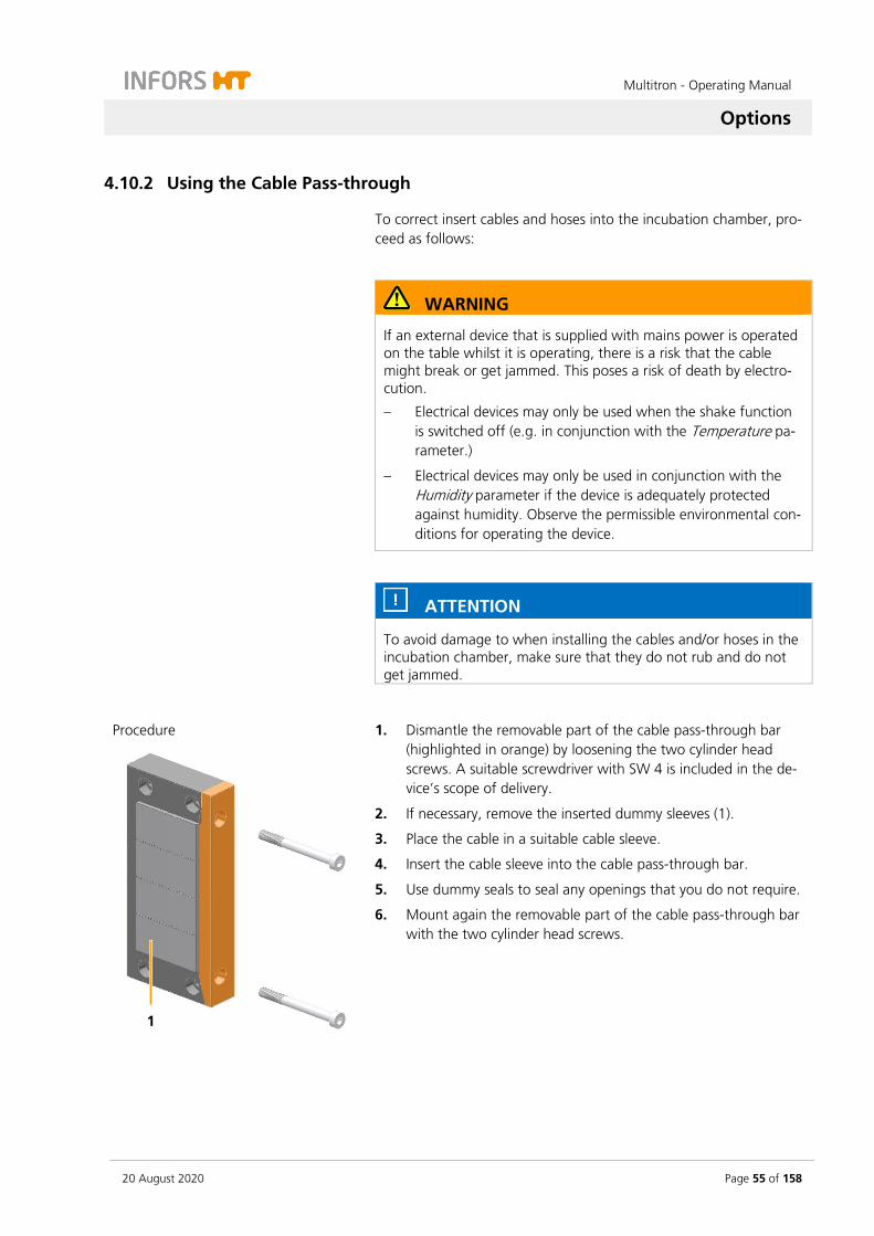
The cable pass-through consists of a dividable cable-pass-through bar (1) into which slotted sealing elements (cable sleeves) (2) can be in-serted. The cables are affixed and strain-relieved using cable sleeves. Openings that are not required are sealed using a dummy sleeve. The cable pass-through is screwed onto the inside of the casing. A suita-ble screw driver (SW 4) is included to dismantle the removable part of the cable pass-through bar (3).
1
2
3
Multitron - Operating Manual
Options
20 August 2020 Page 55 of 158
4.10.2 Using the Cable Pass-through
To correct insert cables and hoses into the incubation chamber, pro-ceed as follows:
WARNING
If an external device that is supplied with mains power is operated on the table whilst it is operating, there is a risk that the cable might break or get jammed. This poses a risk of death by electro-cution.
– Electrical devices may only be used when the shake function is switched off (e.g. in conjunction with the Temperature pa-rameter.)
– Electrical devices may only be used in conjunction with the Humidity parameter if the device is adequately protected against humidity. Observe the permissible environmental con-ditions for operating the device.
ATTENTION
To avoid damage to when installing the cables and/or hoses in the incubation chamber, make sure that they do not rub and do not get jammed.
Procedure
1. Dismantle the removable part of the cable pass-through bar (highlighted in orange) by loosening the two cylinder head screws. A suitable screwdriver with SW 4 is included in the de-vice’s scope of delivery.
2. If necessary, remove the inserted dummy sleeves (1).
3. Place the cable in a suitable cable sleeve.
4. Insert the cable sleeve into the cable pass-through bar.
5. Use dummy seals to seal any openings that you do not require.
6. Mount again the removable part of the cable pass-through bar with the two cylinder head screws.
1

Multitron - Operating Manual
Options
Page 56 of 158 20 August 2020
4.11 Antimicrobial Coating
The housing of the device can be provided with an antimicrobial coating if requested. This contains a lacquer additive made of pure metallic silver that reliably kills microorganisms that come into con-tact with the surface. This can prevent the growth of bacteria, fungi and other microorganisms on the surfaces in the incubation chamber. The door of the device is always provided with an antimicrobial coat-ing, even if the option was not ordered.
INFORMATION
The inner side of the incubation chamber as well as the door can become slightly discoloured due to the silver in the lacquer. This discoloration has no negative impact on the antimicrobial charac-teristics of the coating or the cultivated product.
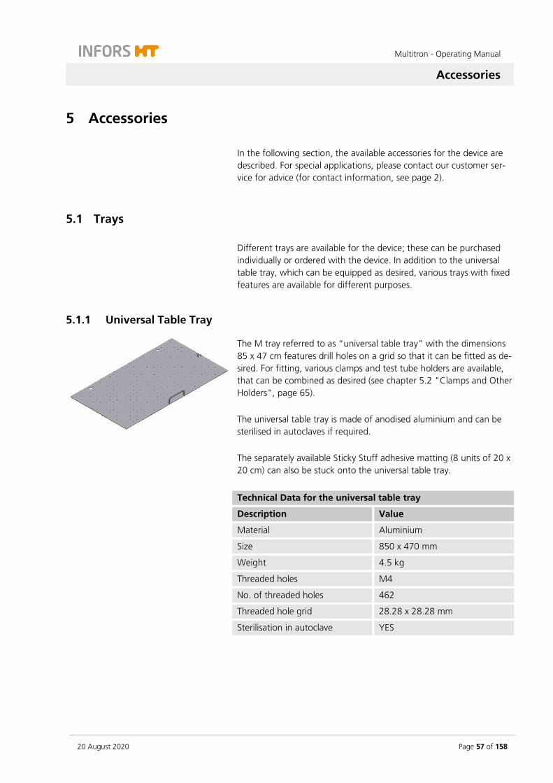
Multitron - Operating Manual
Accessories
20 August 2020 Page 57 of 158
5 Accessories
In the following section, the available accessories for the device are described. For special applications, please contact our customer ser-vice for advice (for contact information, see page 2).
5.1 Trays
Different trays are available for the device; these can be purchased individually or ordered with the device. In addition to the universal table tray, which can be equipped as desired, various trays with fixed features are available for different purposes.
5.1.1 Universal Table Tray
The M tray referred to as “universal table tray” with the dimensions 85 x 47 cm features drill holes on a grid so that it can be fitted as de-sired. For fitting, various clamps and test tube holders are available, that can be combined as desired (see chapter 5.2 "Clamps and Other Holders", page 65). The universal table tray is made of anodised aluminium and can be sterilised in autoclaves if required. The separately available Sticky Stuff adhesive matting (8 units of 20 x 20 cm) can also be stuck onto the universal table tray.
Technical Data for the universal table tray
Description Value
Material Aluminium
Size 850 x 470 mm
Weight 4.5 kg
Threaded holes M4
No. of threaded holes 462
Threaded hole grid 28.28 x 28.28 mm
Sterilisation in autoclave YES

Multitron - Operating Manual
Accessories
Page 58 of 158 20 August 2020
5.1.2 Pre-Fitted Trays
Pre-fitted trays are equipped with one clamp type each. They are used if only a single size of flask is to be used for certain tasks. Unlike the universal table tray, their holders cannot be changed.
Pre-fitted trays feature a capacity that is up to 20 % higher than an individually equipped universal table tray. Since no drill holes have to be taken into account in the grid, the clamps can be installed closer together.
The following versions are available:
Tray with steel clamps
Tray with pin holders for microtitre and deep-well plates
Tray with clamps for microtitre and deep-well plates
Tray with sliding bars
Tray with Sticky Stuff
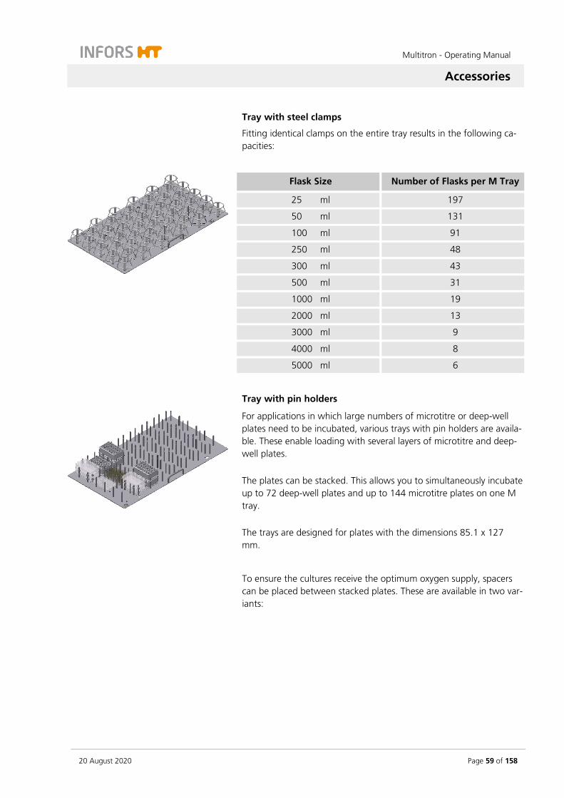
Multitron - Operating Manual
Accessories
20 August 2020 Page 59 of 158
Tray with steel clamps
Fitting identical clamps on the entire tray results in the following ca-pacities:
Flask Size Number of Flasks per M Tray
25 ml 197
50 ml 131
100 ml 91
250 ml 48
300 ml 43
500 ml 31
1000 ml 19
2000 ml 13
3000 ml 9
4000 ml 8
5000 ml 6
Tray with pin holders
For applications in which large numbers of microtitre or deep-well plates need to be incubated, various trays with pin holders are availa-ble. These enable loading with several layers of microtitre and deep-well plates. The plates can be stacked. This allows you to simultaneously incubate up to 72 deep-well plates and up to 144 microtitre plates on one M tray. The trays are designed for plates with the dimensions 85.1 x 127 mm.
To ensure the cultures receive the optimum oxygen supply, spacers can be placed between stacked plates. These are available in two var-iants:

Multitron - Operating Manual
Accessories
Page 60 of 158 20 August 2020
Ring spacers (10 mm high) are placed on the pins individually. Depending on the type of tray loading, this makes it possible to remove individual plates or stacks of plates.
Quickload spacers are long plastic strips (4 mm high) that span across several plates, thus allowing you to save time while loading.
ATTENTION
The spacers are made of plastic and therefore cannot be auto-claved.
Technical data for pin holders
Description Value
Material Aluminium
Fastening screws M5 x 12
Cleaning Mild neutral cleaning agent
Disinfection Commercially available disinfectant
Sterilisation in autoclaves YES
External dimensions of the microtitre plates
85.1 x 127 mm
Height of the deep well plates 42 mm
Tray with clamping assembly
There is a quick clamping assembly for affixing microtitre and deep-well plates. Two versions of this clamping assembly are available:
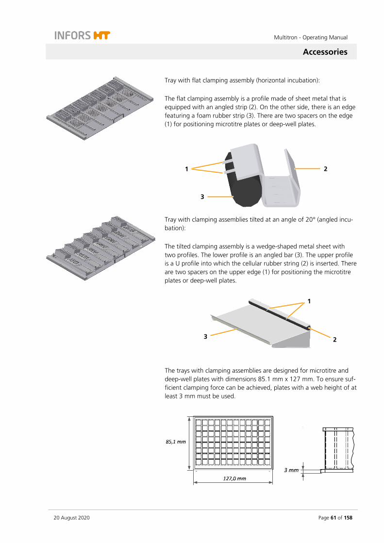
Multitron - Operating Manual
Accessories
20 August 2020 Page 61 of 158
Tray with flat clamping assembly (horizontal incubation): The flat clamping assembly is a profile made of sheet metal that is equipped with an angled strip (2). On the other side, there is an edge featuring a foam rubber strip (3). There are two spacers on the edge (1) for positioning microtitre plates or deep-well plates.
Tray with clamping assemblies tilted at an angle of 20° (angled incu-bation): The tilted clamping assembly is a wedge-shaped metal sheet with two profiles. The lower profile is an angled bar (3). The upper profile is a U profile into which the cellular rubber string (2) is inserted. There are two spacers on the upper edge (1) for positioning the microtitre plates or deep-well plates.
The trays with clamping assemblies are designed for microtitre and deep-well plates with dimensions 85.1 mm x 127 mm. To ensure suf-ficient clamping force can be achieved, plates with a web height of at least 3 mm must be used.
2 1
3
1
2 3

Multitron - Operating Manual
Accessories
Page 62 of 158 20 August 2020
Technical data for clamping assemblies
Description Value
Rail material Aluminium
Foam rubber material CR rubber
Temperature range ≤ 80°C
Cleaning Mild neutral cleaning agent
Disinfection Commercially available disinfectant
Sterilisation NO
Size of microtitre and deep-well plates
85.1 x 127 mm
Tray with sliding bars
Trays with sliding bars allow you to fix vessels of any shape. The slid-ing bars can be affixed to any point on the support bars. This also al-lows you to affix bottles with vertical walls and a curved base. The bars are sheathed in a soft material and arranged on two differ-ent levels in order to securely hold bottles of different sizes. The scope of delivery for the tray includes the fixed frame and 8 mov-able sliding bars.
Technical data for the sliding bars
Description Value
Material Aluminium, plastic
Cellular rubber mat EPDM cellular rubber
Cellular rubber cover Armaflex
Cleaning Mild neutral cleaning agent
Disinfection Commercially available disinfectant
Max. operating temperature 65 °C
Sterilisation in autoclaves NO

Multitron - Operating Manual
Accessories
20 August 2020 Page 63 of 158
5.1.3 Tray with Sticky Stuff
ATTENTION
If condensate forms on the tray or on the cultivation vessels, the adhesiveness of the Sticky Stuff is no longer guaranteed. As a re-sult, cultivation vessels can become detached from the Sticky Stuff and break.
Hence, consider the following when using Sticky Stuff:
– Ensure that no condensate forms on the tray or on the culti-vation vessels. This is especially necessary if cultivation is started at low temperatures and the temperature then is in-creased.
– Let cultivation vessels that were stored in the fridge warm up to ambient temperature first before placing them on the ad-hesive matting.
If you are looking for a very flexible option for equipping the tray, Sticky Stuff offers an ideal alternative.
However, you have to keep in mind that speeds are limited when using Sticky Stuff (for more information on this, refer to the table at the end of the chapter).
About using Sticky Stuff
Use only vessels with a broad flat base. Large Erlenmeyer flasks (e.g. 3000 mL) adhere more strongly than smaller ones (e.g. 500 mL).
Ensure that the entire bases of the flasks are on the adhesive matting. They must not extend beyond the edge of the tray.
Check vessels for damage prior to use and replace, if neces-sary.
Never use damaged vessels!
Prior to putting down any vessel, ensure that its base is dry, clean and grease-free.

Multitron - Operating Manual
Accessories
Page 64 of 158 20 August 2020
Prior to the shaking process, gently pull on every vessel to en-sure they are all stuck on firmly.
If the humidity is too high or the temperatures are too low or if there are extreme jumps in temperature (e.g. when using the timer function), keep an eye on condensate. Condensate can result in vessels detaching from the adhesive matting.
To remove vessels, gently and evenly pull or push on the neck and wait a few seconds.
Never use force!
In case of large vessels, it can take 20 to 30 seconds until they detach from the adhesive matting.
Vessels that are stuck can be removed from the adhesive mat-ting by using a syringe to inject water under the flask.
Due to their shape (wide base, short neck), Fernbach flasks in particular can be difficult to remove. If necessary, cover part of the adhesive matting with the protective foil provided.
The adhesive power can deteriorate over time due to dust and dirt. To clean and restore full adhesive power, thoroughly wipe down the surfaces with a brush or a dish sponge and clear wa-ter with mild detergent (dishwashing liquid). Then let dry over-night.
Quaternary ammonium compounds are suitable for disin-fection.
Consider application times and thoroughly rinse with water. If the adhesive matting is disinfected at regular intervals, it might need to be replaced sooner.
To replace the adhesive matting proceed as follows:
1. Thoroughly spray the tray with water
2. On one side, peel the adhesive matting off the tray and pull it up diagonally.
3. Use acetone to degrease the tray and apply new wet adhesive matting (according to separate installation instructions). Only peel off protective foil prior to use.
The removed adhesive matting can be reused and can be reapplied after regeneration in water. Adhesive matting that is severely worn due to aging must be replaced. This also applies if a reduction in the adhesive force is detected.

Multitron - Operating Manual
Accessories
20 August 2020 Page 65 of 158
INFORMATION
Due to limited resistance to disinfectants as well as the risk of un-intentional detaching of flasks, Sticky Stuff is not suitable for culti-vating pathogenic microorganisms.
Maximum rotation speed with Sticky Stuff
To ensure that the flasks do not detach from the adhesive matting, the maximum permissible speed is limited when using adhesive mat-ting.
INFORMATION
The following guidelines only apply to undamaged, completely dry adhesive matting and flasks free of grease. If old or dirty adhesive matting is used, there is a risk that flasks detach even at lower speeds.
Schott Duran® glass Erlenmeyer flask Filling Maximum permissible speed
25 mm throw 50 mm throw
25 to 750 mL 20 % 250 min-1 200 min-1
1000 mL 20 % 300 min-1 250 min-1
2000 mL 20 % 300 min-1 250 min-1
3000 mL 20 % 350 min-1 300 min-1
5000 mL 20 % 300 min-1 250 min-1
Corning plastic Erlenmeyer flask Filling Maximum permissible speed
25 mm throw 50 mm throw
125 to 3000 mL 20 % 300 min-1 200 min-1
Corning plastic Fernbach flask Filling Maximum permissible speed
25 mm throw 50 mm throw
3000 mL 20 % 300 min-1 250 min-1
5.2 Clamps and Other Holders
For individual fitting of the universal table tray, various clamps and holders are available.

Multitron - Operating Manual
Accessories
Page 66 of 158 20 August 2020
5.2.1 Clamps
Clamps in various sizes are available for equipping a universal table tray. These can be ordered individually and mounted on the universal table tray.
Stainless steel clamps
The following stainless steel clamps are available:
For flask type Volume
Erlenmeyer 25 mL 500 mL 4000 mL
50 mL 1000 mL 5000 mL
100 mL 2000 mL
250 mL 3000 mL
Fernbach 1800 mL 2800 mL
Technical data of the steel clamps
Description Value
Material Stainless steel
Fastening screws 25 up to 50 ml: M4 x 6 100 up to 5000 ml: M4 x 8
Temperature range 95 °C
Cleaning Mild neutral cleaning agent
Disinfection Commercially available disinfectant
Sterilisation in autoclave YES
Plastic clamps
The following plastic clamps are available:
For flask type Volume
Erlenmeyer 100 mL 250 mL 500 mL
Technical data of the plastic clamps
Description Value
Material POM Co polymer
Fastening screws M4 x 6
Temperature range 65 °C
Cleaning Mild neutral cleaning agent
Disinfection Commercially available disinfectant
Sterilisation in autoclave NO
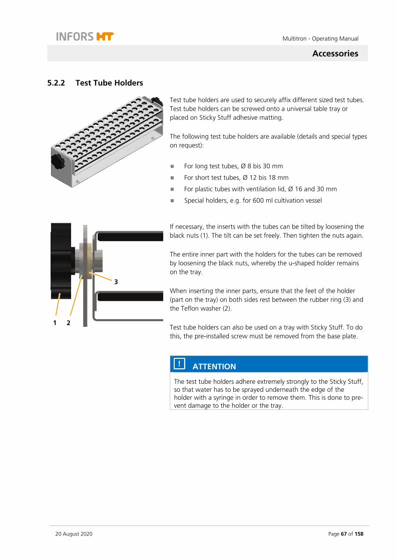
Multitron - Operating Manual
Accessories
20 August 2020 Page 67 of 158
5.2.2 Test Tube Holders
Test tube holders are used to securely affix different sized test tubes. Test tube holders can be screwed onto a universal table tray or placed on Sticky Stuff adhesive matting. The following test tube holders are available (details and special types on request):
For long test tubes, Ø 8 bis 30 mm
For short test tubes, Ø 12 bis 18 mm
For plastic tubes with ventilation lid, Ø 16 and 30 mm
Special holders, e.g. for 600 ml cultivation vessel
If necessary, the inserts with the tubes can be tilted by loosening the black nuts (1). The tilt can be set freely. Then tighten the nuts again. The entire inner part with the holders for the tubes can be removed by loosening the black nuts, whereby the u-shaped holder remains on the tray. When inserting the inner parts, ensure that the feet of the holder (part on the tray) on both sides rest between the rubber ring (3) and the Teflon washer (2). Test tube holders can also be used on a tray with Sticky Stuff. To do this, the pre-installed screw must be removed from the base plate.
ATTENTION
The test tube holders adhere extremely strongly to the Sticky Stuff, so that water has to be sprayed underneath the edge of the holder with a syringe in order to remove them. This is done to pre-vent damage to the holder or the tray.
1 2
3
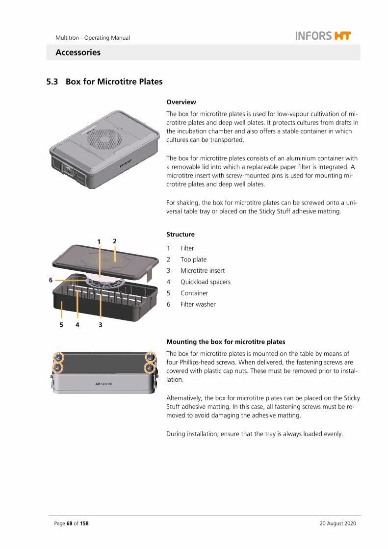
Multitron - Operating Manual
Accessories
Page 68 of 158 20 August 2020
5.3 Box for Microtitre Plates
Overview
The box for microtitre plates is used for low-vapour cultivation of mi-crotitre plates and deep well plates. It protects cultures from drafts in the incubation chamber and also offers a stable container in which cultures can be transported. The box for microtitre plates consists of an aluminium container with a removable lid into which a replaceable paper filter is integrated. A microtitre insert with screw-mounted pins is used for mounting mi-crotitre plates and deep well plates. For shaking, the box for microtitre plates can be screwed onto a uni-versal table tray or placed on the Sticky Stuff adhesive matting.
Structure
1 Filter
2 Top plate
3 Microtitre insert
4 Quickload spacers
5 Container
6 Filter washer
Mounting the box for microtitre plates
The box for microtitre plates is mounted on the table by means of four Phillips-head screws. When delivered, the fastening screws are covered with plastic cap nuts. These must be removed prior to instal-lation. Alternatively, the box for microtitre plates can be placed on the Sticky Stuff adhesive matting. In this case, all fastening screws must be re-moved to avoid damaging the adhesive matting. During installation, ensure that the tray is always loaded evenly.
1 2
3 4 5
6
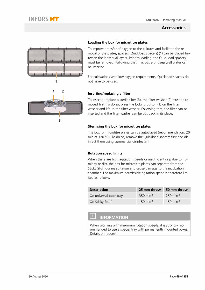
Multitron - Operating Manual
Accessories
20 August 2020 Page 69 of 158
Loading the box for microtitre plates
To improve transfer of oxygen to the cultures and facilitate the re-moval of the plates, spacers (Quickload spacers) (1) can be placed be-tween the individual layers. Prior to loading, the Quickload spacers must be removed. Following that, microtitre or deep well plates can be inserted. For cultivations with low oxygen requirements, Quickload spacers do not have to be used.
Inserting/replacing a filter
To insert or replace a sterile filter (3), the filter washer (2) must be re-moved first. To do so, press the locking button (1) on the filter washer and lift up the filter washer. Following that, the filter can be inserted and the filter washer can be put back in its place.
Sterilising the box for microtitre plates
The box for microtitre plates can be autoclaved (recommendation: 20 min at 120 °C). To do so, remove the Quickload spacers first and dis-infect them using commercial disinfectant.
Rotation speed limits
When there are high agitation speeds or insufficient grip due to hu-midity or dirt, the box for microtitre plates can separate from the Sticky Stuff during agitation and cause damage to the incubation chamber. The maximum permissible agitation speed is therefore lim-ited as follows:
Description 25 mm throw 50 mm throw
On universal table tray 350 min-1 250 min-1
On Sticky Stuff 150 min-1 150 min-1
INFORMATION
When working with maximum rotation speeds, it is strongly rec-ommended to use a special tray with permanently mounted boxes. Details on request.
1
1 2
3
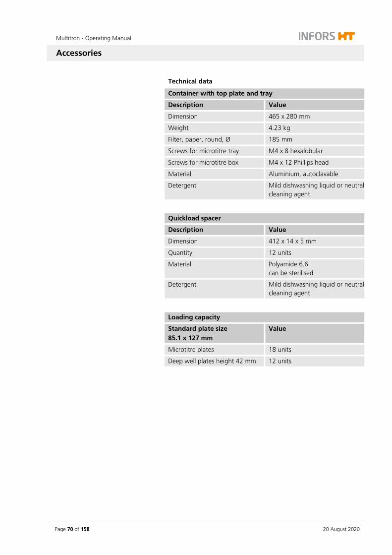
Multitron - Operating Manual
Accessories
Page 70 of 158 20 August 2020
Technical data
Container with top plate and tray
Description Value
Dimension 465 x 280 mm
Weight 4.23 kg
Filter, paper, round, Ø 185 mm
Screws for microtitre tray M4 x 8 hexalobular
Screws for microtitre box M4 x 12 Phillips head
Material Aluminium, autoclavable
Detergent Mild dishwashing liquid or neutral cleaning agent
Quickload spacer
Description Value
Dimension 412 x 14 x 5 mm
Quantity 12 units
Material Polyamide 6.6 can be sterilised
Detergent Mild dishwashing liquid or neutral cleaning agent
Loading capacity
Standard plate size 85.1 x 127 mm
Value
Microtitre plates 18 units
Deep well plates height 42 mm 12 units

Multitron - Operating Manual
Accessories
20 August 2020 Page 71 of 158
5.4 eve®
eve® is a platform software for planning, controlling and analysing bi-oprocesses. Among other features, eve® enables bioprocess data to be recorded and stored in a centrally managed database. The soft-ware offers workflows for simple bioprocesses up to the planning and execution of complex strategies with different process phases. eve® offers the possibility to generate and store bioprocess knowledge. For example, different libraries are available for storing information about organisms or culture media. Thanks to soft sen-sors, additional knowledge can be generated. In addition to INFORS HT products, biotech equipment and analysis devices from third-party manufacturers can also be integrated. In this way, bioprocesses can be controlled, monitored and evaluated en-tirely via one software. eve® is installed on a centralised server. Access takes place via a browser, no client-side installation is required. Bioprocess data is thus directly available via the browser and is independent of the operating system. The software is available in different packages. This allows the soft-ware to be perfectly adapted to the individual needs and require-ments of the users. eve® (in the Premium version) is also suitable for working in a validated environment in accordance with FDA CFR 21 Part 11. Our customer service is at your disposal for detailed information. For contact information, see page 2.

Multitron - Operating Manual
Installation
Page 72 of 158 20 August 2020
6 Installation
Only the manufacturer’s qualified expert personnel or persons au-thorised by the manufacturer may install and initially commission the device. Hence, the following section only lists the requirements for the installation location to be observed by the provider.
WARNING
Installation and initial commissioning require trained expert per-sonnel with sufficient experience. Errors during installation may lead to dangerous situations or significant damage to property.
– Only the manufacturer’s expert personnel or person’s author-ised by the manufacturer may install and initially commission the device.
– The manufacturer must also be consulted if the device is sub-sequently moved.
6.1 Operating Conditions at the Installation Location
To achieve optimal and reproducible results, the device should be set up in stable ambient conditions without strong temperature or hu-midity fluctuations. Changes in ambient temperature or humidity (even short-term) can have a negative effect on the climate in the incubation chamber.
Operating conditions
Temperature range 10 up to 30 °C
Humidity 10 up to 85 %
Restrictions Do not expose to direct sun-light
Do not expose to dust
Do not expose to vibrations
The device may only be set up indoors.

Multitron - Operating Manual
Installation
20 August 2020 Page 73 of 158
To achieve a stable climate in the incubation chamber and to be able to control the climate accurately, the following installation locations must be avoided:
Poorly ventilated recesses or in the exhaust heat air stream of air conditioners or other sources of heat
Directly underneath, next to or in the air stream of the air condi-tioners or other devices that generate strong air flows (e.g. cir-culation fans in clean rooms)
Next to devices with strong heat radiation, such as heaters or autoclaves, or in their exhaust heat air stream
Next to devices for refrigeration, such as ultra-low temperature freezers or refrigerated centrifuges, or in their exhaust heat air stream
INFORMATION
In order to achieve the desired temperature in the incubation chamber, the ambient temperature directly at the device is deci-sive. This can be considerably higher than the temperature at other positions in the room due to waste heat from the device or other devices with strong heat radiation in the immediate vicinity!
6.2 Requirements for the Mains Connection
To avoid dangers due to electrical current, the in-house mains con-nection must meet the following requirements:
Single-phase, constant power supply
In the building, the power supply must be protected using a fault current protection switch (RCD – Residual Current Device).
In addition to that, the following requirements must be met:
Make sure that the voltage values of the device match those of the local power supply. Note the description on the identifica-tion plate.
Only use the power cable provided. If the power cable becomes defective, replace it with a power cable of the same type.
Ensure that the mains connection is accessible at all times.
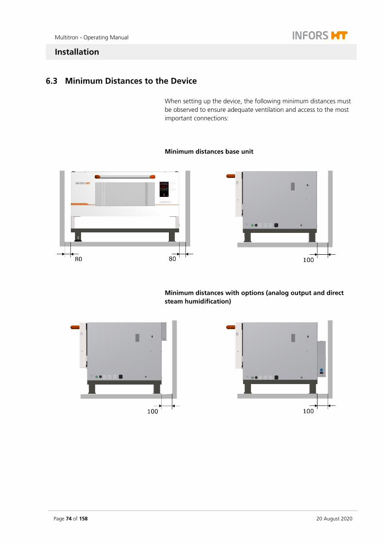
Multitron - Operating Manual
Installation
Page 74 of 158 20 August 2020
6.3 Minimum Distances to the Device
When setting up the device, the following minimum distances must be observed to ensure adequate ventilation and access to the most important connections:
Minimum distances base unit
Minimum distances with options (analog output and direct steam humidification)

Multitron - Operating Manual
Installation
20 August 2020 Page 75 of 158
Placing the device under a table
When placing the device under a table, observe the following:
You must leave a ventilation gap of at least 100 mm between the device and rear wall of the table to ensure heat produced by the device can escape.
The minimum distance between the device and the underside of the table top is 100 mm.
When operating the device with installed cooling, heat can ac-cumulate under a closed laboratory bench. This can result in the desired temperature in the incubation chamber not being reached. In addition, heat accumulation increases power con-sumption, as more cooling is required. Hence, we recommend only installing the device under a laboratory bench with air vents.
ATTENTION
Failure to comply with the required minimum distances can result in components of the device overheating and the device being damaged. Therefore, please note:
– Never cover the air vents on the right side or those on the rear of the device.
– Never position the device directly on a wall.

Multitron - Operating Manual
Operation
Page 76 of 158 20 August 2020
7 Operation
7.1 Switching on the Device
ATTENTION
The shaker drive can start automatically if the device has not been switched off correctly beforehand. Loose objects in the incubation room can damage the device and the cultivation vessels.
1. Press the power switch on the right side of the casing.
The power switch lights up in green after switching on. The de-vice undergoes an initialisation process where various messages appear on the alphanumeric display. As soon as the initialisation process is finished, the device is ready for operation.
7.2 Loading the Device
7.2.1 Opening the Door
Door lock
The door can be opened while the device is running. The shaker drive, temperature control and all other parameters are stopped au-tomatically. When the door is fully opened, the tray is released and can be pulled outwards if required.
At rotation speeds of up to 200 min-1, the door can be opened with-out restrictions. If the device is operated at a rotation speed of more than 200 min-1, the door is locked temporarily and cannot be opened fully until the table has come to a full stop.
To open the door during operation at rotation speeds higher than 200 min-1, proceed as follows:
Procedure 1. Open the door halfway and wait until the table has stopped. You can hear a click when the door opening is released.
2. Open the door completely. If the door does not unlock straight away, lift it up slightly to take the load off the locking mecha-nism.
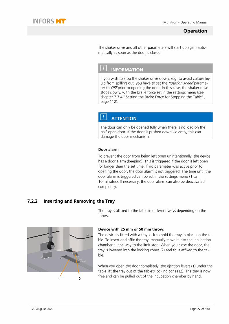
Multitron - Operating Manual
Operation
20 August 2020 Page 77 of 158
The shaker drive and all other parameters will start up again auto-matically as soon as the door is closed.
INFORMATION
If you wish to stop the shaker drive slowly, e.g. to avoid culture liq-uid from spilling out, you have to set the Rotation speed parame-ter to OFF prior to opening the door. In this case, the shaker drive stops slowly, with the brake force set in the settings menu (see chapter 7.7.4 "Setting the Brake Force for Stopping the Table", page 112).
ATTENTION
The door can only be opened fully when there is no load on the half-open door. If the door is pushed down violently, this can damage the door mechanism.
Door alarm
To prevent the door from being left open unintentionally, the device has a door alarm (beeping). This is triggered if the door is left open for longer than the set time. If no parameter was active prior to opening the door, the door alarm is not triggered. The time until the door alarm is triggered can be set in the settings menu (1 to 10 minutes). If necessary, the door alarm can also be deactivated completely.
7.2.2 Inserting and Removing the Tray
The tray is affixed to the table in different ways depending on the throw.
Device with 25 mm or 50 mm throw: The device is fitted with a tray lock to hold the tray in place on the ta-ble. To insert and affix the tray, manually move it into the incubation chamber all the way to the limit stop. When you close the door, the tray is lowered into the locking cones (2) and thus affixed to the ta-ble. When you open the door completely, the ejection levers (1) under the table lift the tray out of the table’s locking cones (2). The tray is now free and can be pulled out of the incubation chamber by hand.
2 1

Multitron - Operating Manual
Operation
Page 78 of 158 20 August 2020
Device with 3 mm throw: To insert the tray, manually move it into the incubation chamber all the way to the limit stop and lower it into the locking cones (1) in the front section of the table. The tray then has to be affixed to the table using a knurled screw (2). To remove the tray from the incubation chamber, the knurled screw has to be unscrewed again. Following that, the tray can be lifted out of the locking cones and be pulled out of the incubation chamber by hand.
Removing the Tray
The tray is always removed from the incubation chamber in the same way, irrespective of the throw. The tray is pulled onto the door by hand. Slide rails (2) and the cylindrical ball casters therein (1) on the door guide the tray. Two stop bars (3) in the slide rails limit how far the tray can be pulled out. When pulled out all the way, the tray lies partially on the door and partially on the table. Proceed as follows:
Procedure 1. Open the device door all the way.
Device with 25 mm or 50 mm throw: The safety mechanism lifts the tray out of the cones. The tray is thus free and can be pulled out of the incubation chamber.
2. Device with 3 mm throw: Loosen the knurled screw and re-move it
3. Lift the tray by the handle.
4. Pull the tray over the front stop bar and onto the open door. If you cannot pull the tray out, check whether the door is open all the way. Push the door down as far as it will go.
Inserting the Tray
To insert the tray, proceed as follows:
Procedure 1. Open the device door all the way.
2 1
3
1 2 1
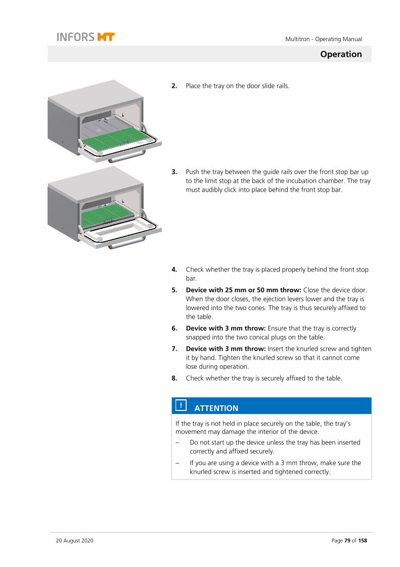
Multitron - Operating Manual
Operation
20 August 2020 Page 79 of 158
2. Place the tray on the door slide rails.
3. Push the tray between the guide rails over the front stop bar up to the limit stop at the back of the incubation chamber. The tray must audibly click into place behind the front stop bar.
4. Check whether the tray is placed properly behind the front stop bar.
5. Device with 25 mm or 50 mm throw: Close the device door. When the door closes, the ejection levers lower and the tray is lowered into the two cones. The tray is thus securely affixed to the table.
6. Device with 3 mm throw: Ensure that the tray is correctly snapped into the two conical plugs on the table.
7. Device with 3 mm throw: Insert the knurled screw and tighten it by hand. Tighten the knurled screw so that it cannot come lose during operation.
8. Check whether the tray is securely affixed to the table.
ATTENTION
If the tray is not held in place securely on the table, the tray’s movement may damage the interior of the device.
– Do not start up the device unless the tray has been inserted correctly and affixed securely.
– If you are using a device with a 3 mm throw, make sure the knurled screw is inserted and tightened correctly.

Multitron - Operating Manual
Operation
Page 80 of 158 20 August 2020
Tray cannot be inserted
If you are unable to insert the tray correctly, perform the following checks:
Remove the tray and check it is not twisted or bent.
Check the incubation chamber for foreign matter and other ob-jects.
If it is still not possible to insert the tray correctly, contact your local INFORS HT representative.
7.2.3 Fitting the Holders
ATTENTION
The threaded holes of the tray can be damaged if the fastening screws are not screwed straight into the thread:
– Place the screws vertically on the drill holes.
– Ensure they can be tightened easily.
ATTENTION
All holders are supplied with pre-fitted screws. If a test tube holder or a box for microtiter plates is placed on the Sticky Stuff adhesive matting, there is a risk that the adhesive matting is damaged by protruding screws.
Remove the screws before you place test tube holders or boxes for microtiter plates on the Sticky Stuff adhesive matting.
Fitting a holder
Clamps, test tubes and boxes for microtiter plates are fixed to the tray using screws. The device is delivered with pre-fitted screws (2). The screws are each secured with one flat gasket at the bottom (1) so that they cannot fall out. Only use the screws provided or screws of the same size for assembly.
To fit a holder, proceed as follows:
1
2
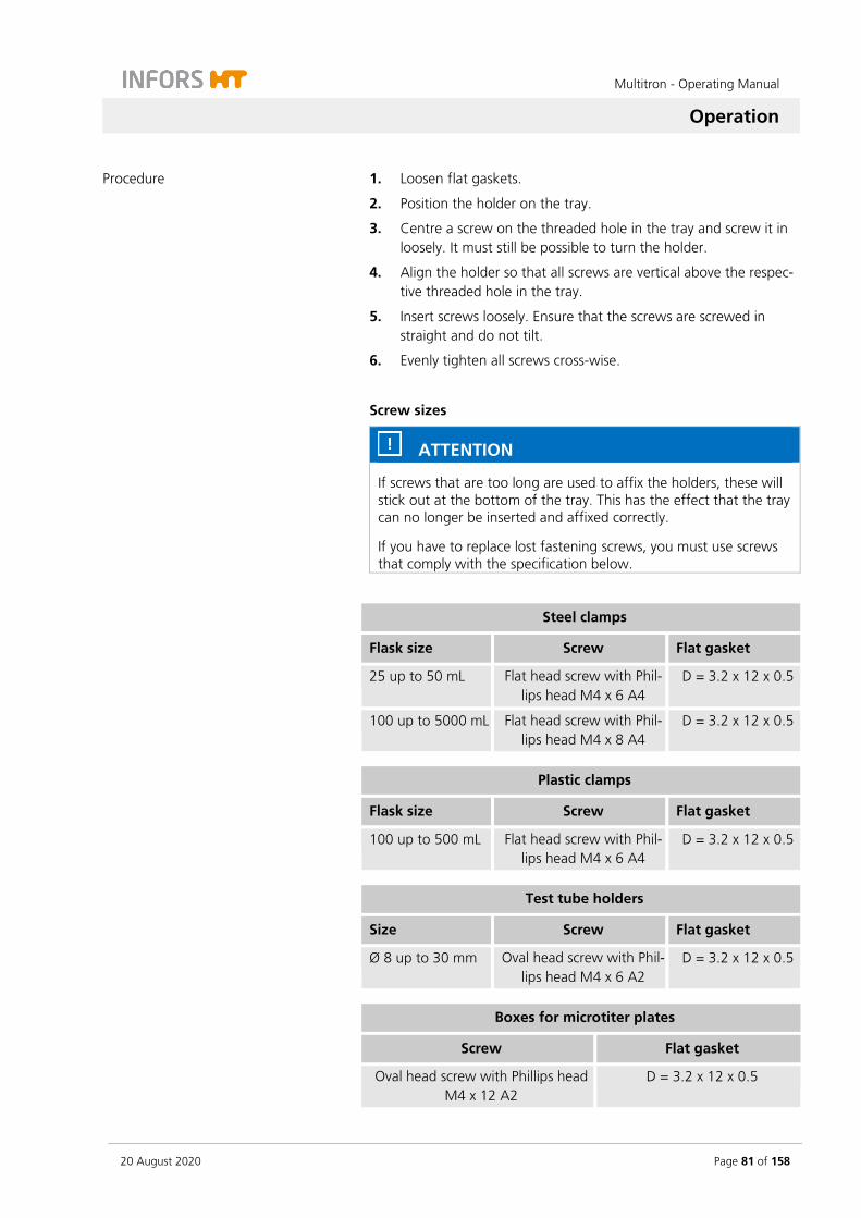
Multitron - Operating Manual
Operation
20 August 2020 Page 81 of 158
Procedure 1. Loosen flat gaskets.
2. Position the holder on the tray.
3. Centre a screw on the threaded hole in the tray and screw it in loosely. It must still be possible to turn the holder.
4. Align the holder so that all screws are vertical above the respec-tive threaded hole in the tray.
5. Insert screws loosely. Ensure that the screws are screwed in straight and do not tilt.
6. Evenly tighten all screws cross-wise.
Screw sizes
ATTENTION
If screws that are too long are used to affix the holders, these will stick out at the bottom of the tray. This has the effect that the tray can no longer be inserted and affixed correctly.
If you have to replace lost fastening screws, you must use screws that comply with the specification below.
Steel clamps
Flask size Screw Flat gasket
25 up to 50 mL Flat head screw with Phil-lips head M4 x 6 A4
D = 3.2 x 12 x 0.5
100 up to 5000 mL Flat head screw with Phil-lips head M4 x 8 A4
D = 3.2 x 12 x 0.5
Plastic clamps
Flask size Screw Flat gasket
100 up to 500 mL Flat head screw with Phil-lips head M4 x 6 A4
D = 3.2 x 12 x 0.5
Test tube holders
Size Screw Flat gasket
Ø 8 up to 30 mm Oval head screw with Phil-lips head M4 x 6 A2
D = 3.2 x 12 x 0.5
Boxes for microtiter plates
Screw Flat gasket
Oval head screw with Phillips head M4 x 12 A2
D = 3.2 x 12 x 0.5
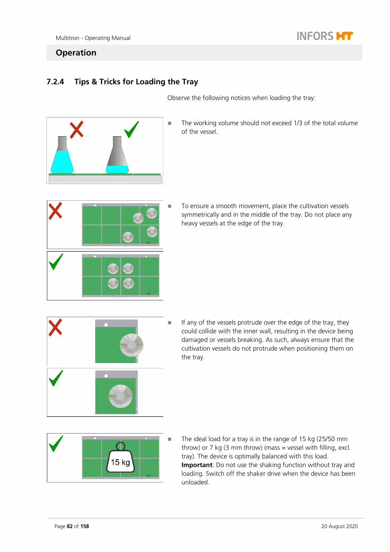
Multitron - Operating Manual
Operation
Page 82 of 158 20 August 2020
7.2.4 Tips & Tricks for Loading the Tray
Observe the following notices when loading the tray:
The working volume should not exceed 1/3 of the total volume of the vessel.
To ensure a smooth movement, place the cultivation vessels symmetrically and in the middle of the tray. Do not place any heavy vessels at the edge of the tray.
If any of the vessels protrude over the edge of the tray, they could collide with the inner wall, resulting in the device being damaged or vessels breaking. As such, always ensure that the cultivation vessels do not protrude when positioning them on the tray.
The ideal load for a tray is in the range of 15 kg (25/50 mm throw) or 7 kg (3 mm throw) (mass = vessel with filling, excl. tray). The device is optimally balanced with this load. Important: Do not use the shaking function without tray and loading. Switch off the shaker drive when the device has been unloaded.
Multitron - Operating Manual
Operation
20 August 2020 Page 83 of 158
Stacked devices
With devices stacked in three, very low loads (< 10 kg per unit) and high rotation speeds (> 300 min-1) at the same time can result in vi-brations occur. In this case it is recommended to place additional cul-tivation vessels filled with water on the tray. This ensures a smooth run. With a load of more than 10 kg per unit, no significant vibra-tions occur and the device can be operated over the entire rotation speed range without any limitations.
WARNING
If the loading mass of the table is too high or too low or the load is distributed unevenly, high rotation speeds can cause vibrations. This can result in the device moving uncontrollably.
– Do not operate the device without tray and loading.
– In case of strong vibrations, reduce the rotation speed and check the loading weights or the distribution of the load.

Multitron - Operating Manual
Operation
Page 84 of 158 20 August 2020
7.3 Overview about the Display und Controls
1 Complete display area
2 Upper display: Parameter setpoints and actual values (temperature, CO2, light); time (timer 1)
3 Error and warning messages, alarm
4 Lower display: Parameter setpoints and actual values (RPM, humidity); time (timer 2)
5 Display area for the timer function
6 Display for the ethernet function when the de-vice is operated via ethernet
7 Complete operating panel
8 Upper operating panel: For setting the parameters (temperature, CO2, light), time (timer 1)
9 Lower operating panel: For setting the parameters (RPM, humidity), time (timer 2)
10 Further operating keys (selection, TIMER and OPTION)
Parameters in gray are only available when the according option is installed.
7 1
8
3
4 9
5
6
2
10
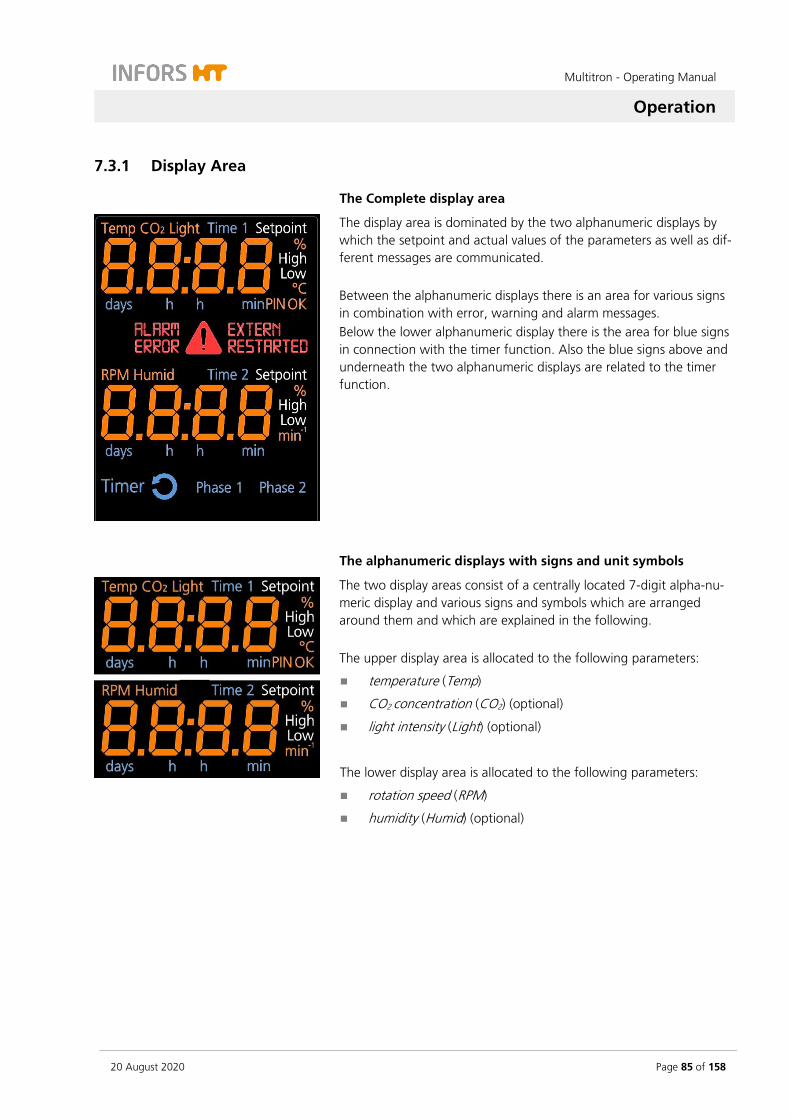
Multitron - Operating Manual
Operation
20 August 2020 Page 85 of 158
7.3.1 Display Area
The Complete display area
The display area is dominated by the two alphanumeric displays by which the setpoint and actual values of the parameters as well as dif-ferent messages are communicated. Between the alphanumeric displays there is an area for various signs in combination with error, warning and alarm messages. Below the lower alphanumeric display there is the area for blue signs in connection with the timer function. Also the blue signs above and underneath the two alphanumeric displays are related to the timer function.
The alphanumeric displays with signs and unit symbols
The two display areas consist of a centrally located 7-digit alpha-nu-meric display and various signs and symbols which are arranged around them and which are explained in the following. The upper display area is allocated to the following parameters:
temperature (Temp)
CO2 concentration (CO2) (optional)
light intensity (Light) (optional)
The lower display area is allocated to the following parameters:
rotation speed (RPM)
humidity (Humid) (optional)

Multitron - Operating Manual
Operation
Page 86 of 158 20 August 2020
7.3.2 Signs and Messages Regarding the Timer Function
In the upper and lower display area
All signs and symbols in connection with the timer information – ex-cept the duration which needs to be entered – light up in blue.
In the upper display area the sign Time 1 lights up, when within the timer function (see below) the setpoint value for the duration of the first phase (Phase 1) can be entered. First, the message OFF appears, if the timer is not activated. In a similar way but not at the same time, the according information for the second phase (Phase 2, Time 2) is shown in the lower display area.
On both alphanumeric displays the time for the timer function is shown. When entering a time between one minute (00:01) and 23 hours and 59 minutes (23:59) the units h and min light up. When entering a time between 24 hours or one day (01:00) and the maximum of 9 days and 23 hours (09:23) the units days and h light up.
In the separate timer display area
In the separate timer display area there are the four signs Timer, a symbol for cycle, Phase 1, und Phase 2.
The sign Timer indicates that either within the timer function the set-points for the duration (Time 1 and/or Time 2) can be entered or that at least one timer has been activated.
The symbol for the cycle mode lights up in addition to the sign Timer as soon as two durations (Time 1 and Time 2) have been entered and both timers are activated. Then the device alters between the param-eter setpoints of the first and the second phase in an endlessly re-peated cycle.
/
The signs Phase 1 and Phase 2 indicate in which phase the device is operating if both timers are active with different parameter settings. They also indicate for which phase (Time 1 or Time 2) the parameter setpoints can be entered or the actual values of the parameters are shown on the alphanumeric display.

Multitron - Operating Manual
Operation
20 August 2020 Page 87 of 158
7.3.3 Error, Warning, and Alarm Signs
Between the upper and the lower alphanumeric display area there is a separate field with various signs associated with error, warning, and alarm messages.
The big red general symbol for warnings lights up in connection with error messages and alarms to emphasise the importance of the mes-sage. It always flashes up when the setpoints are changed to avoid mis-takes. The warning symbol also lights up, if somebody tries to enter a setpoint value or tapping the ON/OFF key without tapping the SET key first. In addition, it also appears if someone tries to enter an inva-lid setpoint value.
The sign ALARM appears in connection with other signs like ERROR, High or Low and it indicates that there is a problem with the device. In addition, there will be an acoustic alarm.
The sign ERROR indicates that an error occurred in the operation of the device which provoked an error message. In connection with the sign ERROR there are often messages on the alphanumeric display which give some more detailed information on what happened. For the according abbreviations (see chapter 8 "Rec-tifying Faults", page 118).
The sign EXTERN lights up when the device is controlled externally (e.g. by means of a bioprocess software).
The sign RESTARTED indicates that the device had been disconnected from the power supply and did restart automatically on the basis of the saved parameter setpoints.

Multitron - Operating Manual
Operation
Page 88 of 158 20 August 2020
7.3.4 Operating Panel
The various keys on the operating panel serve to select and set the parameters, timers and other functions and modes. On the panel there are selection keys in orange (parameters, operator mode) and in blue (timer function) as well as white keys for the setting. The white keys for the setting exist twice because they are arranged in an upper and a lower group within the operating key area which corresponds with the according display area.
INFORMATION
The sensor controlled soft-touch keys are behind a glass cover and they only need to be touched very gently.
INFORMATION
Tapping an arbitrary key on the operating panel turns on the light inside the incubation chamber. 20 seconds after tapping the last key it is automatically turned off.
Keys for selecting
With the Select key the parameters and functions are selected within the timer function or the operator mode. The symbol of the selected parameter or timer (Time 1 or Time 2) is displayed in the upper or lower display area.
With the TIMER key the timer function is selected. Afterwards, the two timers can be programmed using the keys in the upper or lower operating area. On both display areas the symbols Time 1 (upper area) und Time 2 (lower area) are displayed For detailed information see chapter 7.5 "Timer Function", page 95.
By holding the OPTION key for at least 2 seconds the operator mode is selected. It allows to change the setup of the device. The OPTION key is also used to select the functions within the opera-tor mode. For detailed information see chapter 7.7 "Settings Menu (Option Function)", page 111.

Multitron - Operating Manual
Operation
20 August 2020 Page 89 of 158
Keys for setting
After tapping the SET key the parameter setpoints or the duration for the timer can be entered. In the according display area the sign Setpoint lights up.
With the Plus key the values for the parameters or the time are in-creased. By tapping the key once, the value is increased with the smallest in-crement for the particular parameter. By holding the key, the incre-ment increases in ever bigger steps.
With the Minus key the values for the parameters or the time are re-duced. By tapping the key once, the value is reduced with the smallest incre-ment for the particular parameter. By holding the key, the increment increases in ever bigger steps.
The ON/OFF key serves to turn the parameters and timers on or off.
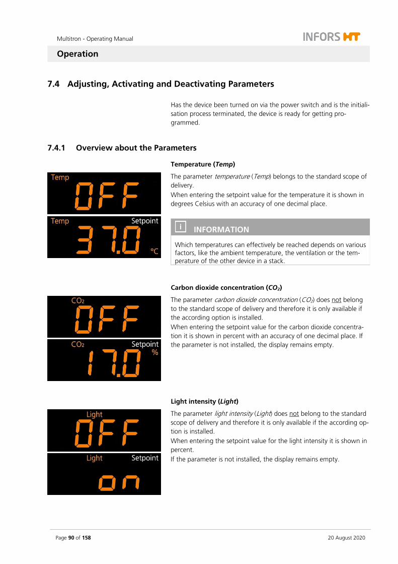
Multitron - Operating Manual
Operation
Page 90 of 158 20 August 2020
7.4 Adjusting, Activating and Deactivating Parameters
Has the device been turned on via the power switch and is the initiali-sation process terminated, the device is ready for getting pro-grammed.
7.4.1 Overview about the Parameters
Temperature (Temp)
The parameter temperature (Temp) belongs to the standard scope of delivery. When entering the setpoint value for the temperature it is shown in degrees Celsius with an accuracy of one decimal place.
INFORMATION
Which temperatures can effectively be reached depends on various factors, like the ambient temperature, the ventilation or the tem-perature of the other device in a stack.
Carbon dioxide concentration (CO2)
The parameter carbon dioxide concentration (CO2) does not belong to the standard scope of delivery and therefore it is only available if the according option is installed. When entering the setpoint value for the carbon dioxide concentra-tion it is shown in percent with an accuracy of one decimal place. If the parameter is not installed, the display remains empty.
Light intensity (Light)
The parameter light intensity (Light) does not belong to the standard scope of delivery and therefore it is only available if the according op-tion is installed. When entering the setpoint value for the light intensity it is shown in percent. If the parameter is not installed, the display remains empty.

Multitron - Operating Manual
Operation
20 August 2020 Page 91 of 158
Rotation speed (RPM)
The parameter rotation speed (RPM) belongs to the standard scope of delivery. When entering the setpoint value for the rotation speed it is shown in rpm (min-1) with an accuracy of one whole number.
INFORMATION
The highest rotation speed allowed depends on the throw, the po-sition of the device in a stack and the load on the tray (mass).
Humidity (Humid)
The parameter humidity (Humid) does not belong to the standard scope of delivery and therefore it is only available if the according op-tion is installed. When entering the setpoint value for the relative humidity it is shown in percent with an accuracy of one decimal place. If the parameter is not installed, the display remains empty.
Parameter-specific display elements
The sign Setpoint lights up, when by tapping the SET key on the up-per or lower operating panel the setpoint values for the parameters can be entered.
The sign High or Low lights up, if the current value of a parameter is above respectively below its setpoint value. After a certain time span or when a critical value is reached an alarm will be set off, because most probably an error or defect hinders the device to reach or maintain the setpoint value in question.
The possible setpoints for the parameters rotation speed and temper-ature can be limited in the settings menu. If an attempt is made to enter a higher value, the message bloc appears.
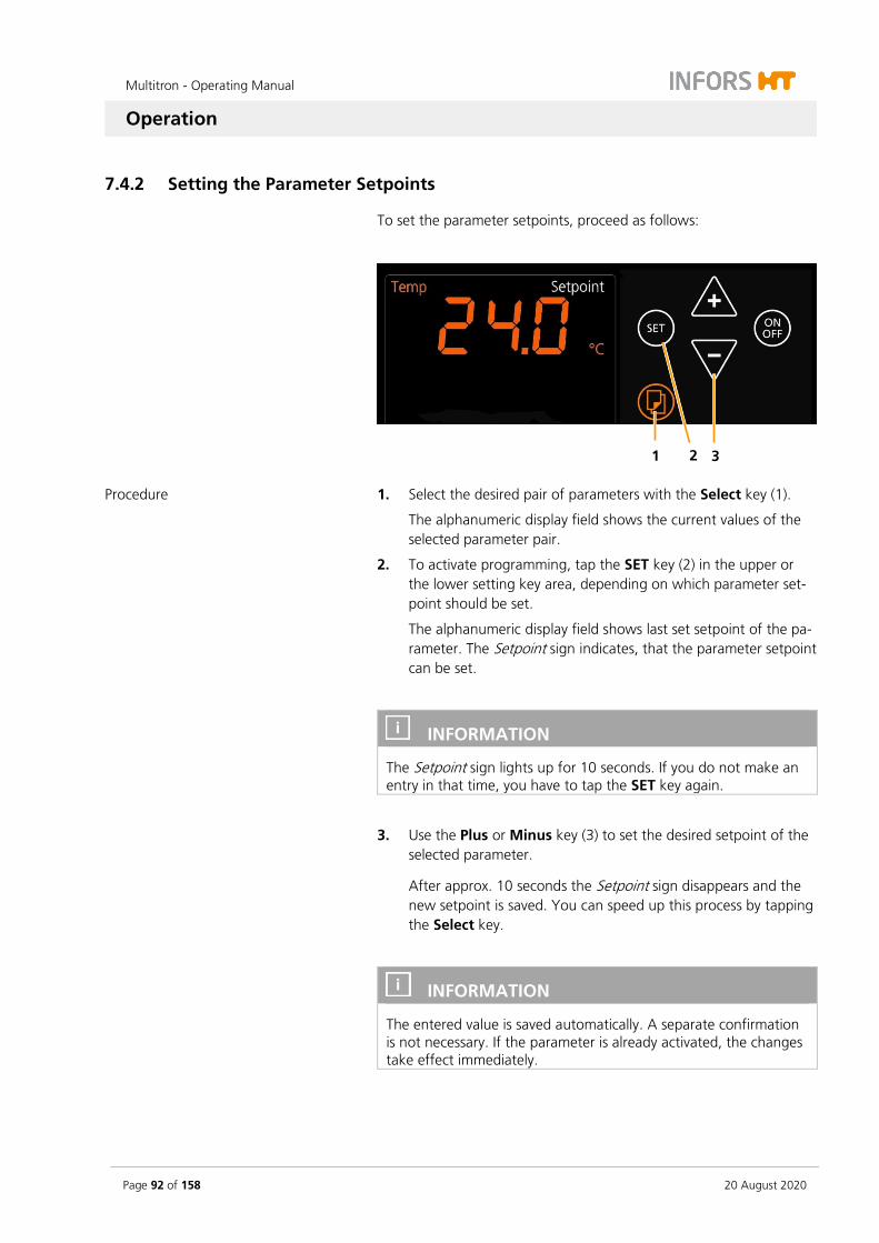
Multitron - Operating Manual
Operation
Page 92 of 158 20 August 2020
7.4.2 Setting the Parameter Setpoints
To set the parameter setpoints, proceed as follows:
Procedure 1. Select the desired pair of parameters with the Select key (1).
The alphanumeric display field shows the current values of the selected parameter pair.
2. To activate programming, tap the SET key (2) in the upper or the lower setting key area, depending on which parameter set-point should be set.
The alphanumeric display field shows last set setpoint of the pa-rameter. The Setpoint sign indicates, that the parameter setpoint can be set.
INFORMATION
The Setpoint sign lights up for 10 seconds. If you do not make an entry in that time, you have to tap the SET key again.
3. Use the Plus or Minus key (3) to set the desired setpoint of the selected parameter.
After approx. 10 seconds the Setpoint sign disappears and the new setpoint is saved. You can speed up this process by tapping the Select key.
INFORMATION
The entered value is saved automatically. A separate confirmation is not necessary. If the parameter is already activated, the changes take effect immediately.
1 2 3
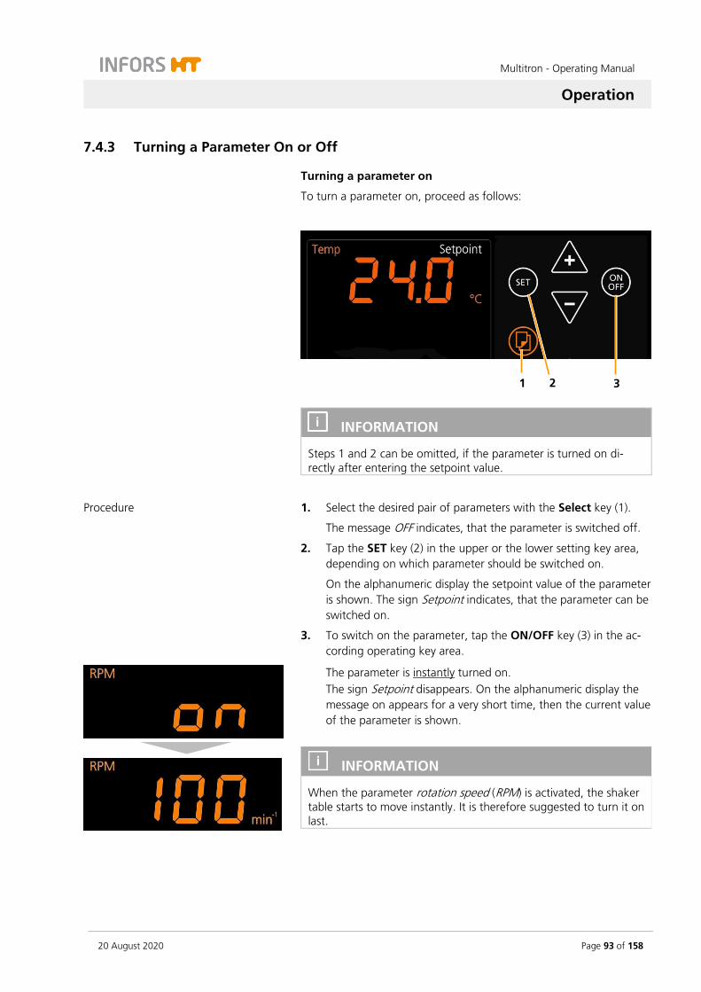
Multitron - Operating Manual
Operation
20 August 2020 Page 93 of 158
7.4.3 Turning a Parameter On or Off
Turning a parameter on
To turn a parameter on, proceed as follows:
INFORMATION
Steps 1 and 2 can be omitted, if the parameter is turned on di-rectly after entering the setpoint value.
Procedure 1. Select the desired pair of parameters with the Select key (1).
The message OFF indicates, that the parameter is switched off.
2. Tap the SET key (2) in the upper or the lower setting key area, depending on which parameter should be switched on.
On the alphanumeric display the setpoint value of the parameter is shown. The sign Setpoint indicates, that the parameter can be switched on.
3. To switch on the parameter, tap the ON/OFF key (3) in the ac-cording operating key area.
The parameter is instantly turned on. The sign Setpoint disappears. On the alphanumeric display the message on appears for a very short time, then the current value of the parameter is shown.
INFORMATION
When the parameter rotation speed (RPM) is activated, the shaker table starts to move instantly. It is therefore suggested to turn it on last.
1 2 3

Multitron - Operating Manual
Operation
Page 94 of 158 20 August 2020
INFORMATION
It takes a while for the parameters to reach the entered setpoint value. The sign High or Low lights up, if the current value of a pa-rameter is above respectively below its setpoint value.
Turning a parameter off
Turning off a parameter is carried out the same way as switching on a parameter. The desired parameter can be selected by tapping the Select key and afterwards switched off by tapping the ON/OFF key. Is the parameter switched off, the message OFF appears on the al-phanumeric display.

Multitron - Operating Manual
Operation
20 August 2020 Page 95 of 158
7.5 Timer Function
7.5.1 Overview
The timer function allows you to programme defined sequences (e.g. changing parameter setpoints after a defined time period or delaying the start of the cultivation process). The timer can be programmed in two different modes:
One-time change from phase 1 to phase 2
Cyclical change between phase 1 and phase 2
INFORMATION
More complex sequences and procedures (e.g. daylight curves) can be realised with the bioprocess platform software eve®.
Signs regarding the timer function
If the timer function is active, the following signs appear:
The sign Timer appears as soon as the timer function is active or if the timer can be programmed.
The signs Time 1 and Time 2 indicate, that the duration of phase 1 (Time 1) respectively phase 2 (Time 2) can be entered.
The signs Phase 1 and Phase 2 indicate which phase is active or for which phase the parameter setpoints can be entered:
The sign is blinking: The phase is active.
The sign is lit up: The parameter setpoints of the corresponding phase can be entered.
If the cyclic change between phase 1 and phase 2 is active, the sign cycle lights up.
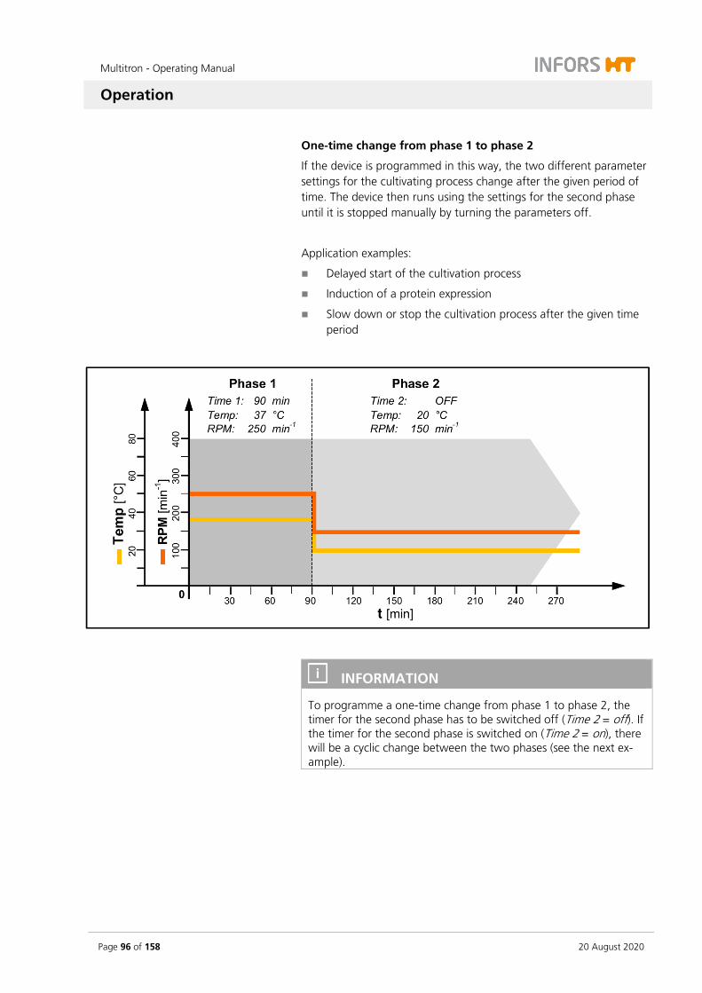
Multitron - Operating Manual
Operation
Page 96 of 158 20 August 2020
One-time change from phase 1 to phase 2
If the device is programmed in this way, the two different parameter settings for the cultivating process change after the given period of time. The device then runs using the settings for the second phase until it is stopped manually by turning the parameters off.
Application examples:
Delayed start of the cultivation process
Induction of a protein expression
Slow down or stop the cultivation process after the given time period
INFORMATION
To programme a one-time change from phase 1 to phase 2, the timer for the second phase has to be switched off (Time 2 = off). If the timer for the second phase is switched on (Time 2 = on), there will be a cyclic change between the two phases (see the next ex-ample).

Multitron - Operating Manual
Operation
20 August 2020 Page 97 of 158
Cyclical change between phase 1 and phase 2
If the device is programmed in this way, two different parameter set-tings are repeated in an endless, precisely timed cycle. The two time intervals (Phase 1 and Phase 2) alternate until the cultivating process is stopped manually by turning the parameters off.
Application example:
Simulation of day and night
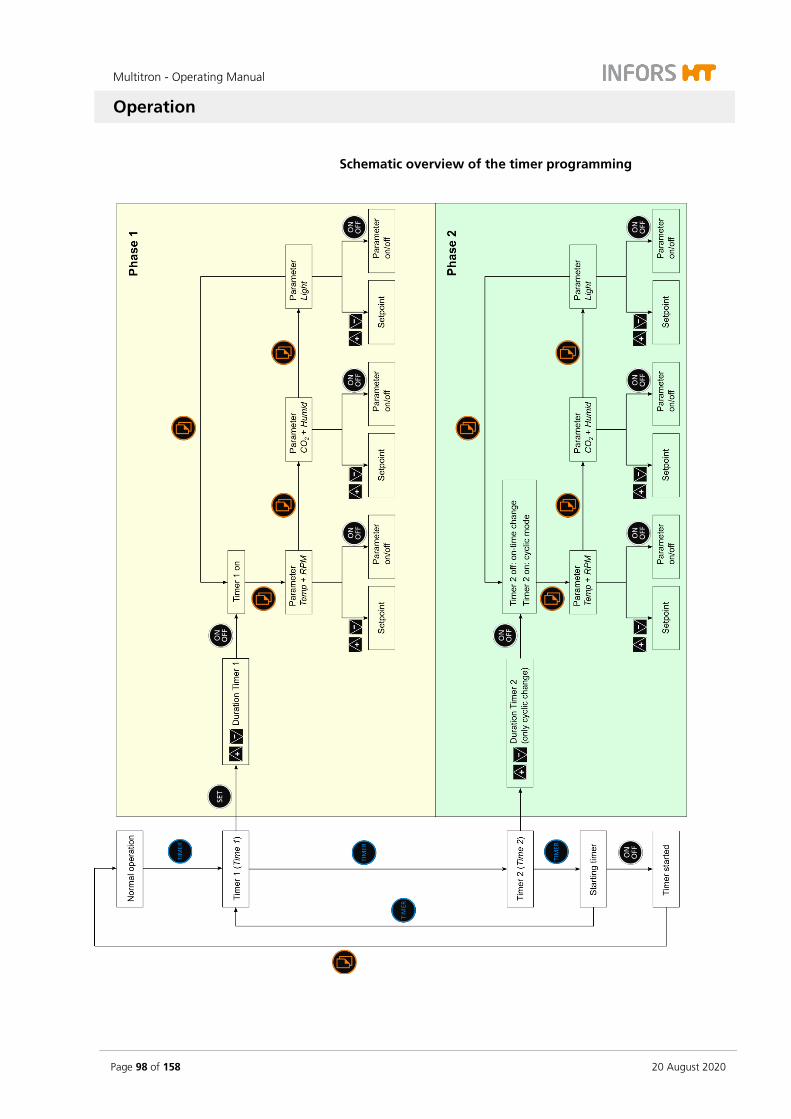
Multitron - Operating Manual
Operation
Page 98 of 158 20 August 2020
Schematic overview of the timer programming

Multitron - Operating Manual
Operation
20 August 2020 Page 99 of 158
7.5.2 Programming the Timer - Single Change
Programming the timer for a single change consists of the following steps:
a) Entering the time for the first phase.
b) Entering the setpoint values for the first phase and switching on the parameters.
c) Making sure that the timer for the second phase (Time 2) is switched off.
d) Entering the setpoint values for the second phase and switch-ing on the parameters.
e) Starting the timer.
Entering the time for the first phase
Procedure 1. Tap the TIMER key to start the timer function.
On the upper alphanumeric display the sign Time 1 and the message OFF appear. Additionally the sign Timer is lit up.
INFORMATION
Possibly the message OFF for the second timer (Time 2) appears on the lower alphanumeric display. Then the TIMER key needs to be tapped again to get to the first timer (Time 1).
2. To set the time, tap the SET key in the upper setting key area.
The sign Setpoint indicates, that the time can be entered.
3. Use the Plus or the Minus key in the upper setting key area to set the time for the first phase (Time 1).
The time set is shown either in hours (h) and minutes (min) or in days (days) and hours (h).

Multitron - Operating Manual
Operation
Page 100 of 158 20 August 2020
4. Tap the ON/OFF key in the upper setting key area to activate the timer (Time 1).
On the upper alphanumeric display the message on appears for a very short time and then the time entered is shown In the separate timer display area the sign Timer is lit up and the sign Phase 1 lights up for the first time.
INFORMATION
It is not possible to set the parameters for the first phase as long as the timer for the first phase has not been activated.
Entering the setpoints for the first phase and switching on the parameters
As soon as the timer for the first phase (Time 1) has been switched on, the different parameters for phase 1 can be selected using the Select key and afterwards be switched on.
5. Tap the Select key to select the desired parameters.
In both display areas the first integral pair of parameters (Temp and RPM) appears with the last setpoint values entered or the message OFF. The sign Setpoint indicates, that the setpoints can be entered.
INFORMATION
In this phase of the programming process the sign Setpoint re-mains lit up and does not disappear after 10 seconds.
6. Tap the Plus or Minus key in the corresponding setting key area to set the desired setpoint values and switch the parameters on using the ON/OFF key.
INFORMATION
With the Select key the parameters and the time entered for the first phase can be selected and changed over and over again.

Multitron - Operating Manual
Operation
20 August 2020 Page 101 of 158
Checking the timer for the second phase
7. Tap the TIMER key to get to the time settings for the second phase (Time 2).
On the lower alphanumeric display appears the time entered last or 00:00 if no time has been entered. In the separate timer display area the signs Timer and Phase 2 are lit up.
8. Make sure the second timer is turned off. If not, use the ON/OFF key in the lower setting key area to turn the timer (Time 2) off.
Entering the setpoints for the second phase and switching on the parameters
After making sure, that the second timer (Time 2) is switched off, the different parameters for phase 2 can be selected using the Select key and afterwards be switched on.
INFORMATION
If the timer should be used to stop the cultivation process after a defined time, all parameters for phase 2 can be switched off. This causes the parameters to switch off after the set time for phase 1 has elapsed and therefore to stop the cultivation process.
9. Tap the Select key to select the desired parameters.
In both display areas the first integral pair of parameters (Temp and RPM) appears with the last setpoint values entered or the message OFF. The sign Setpoint indicates, that the setpoints can be entered.
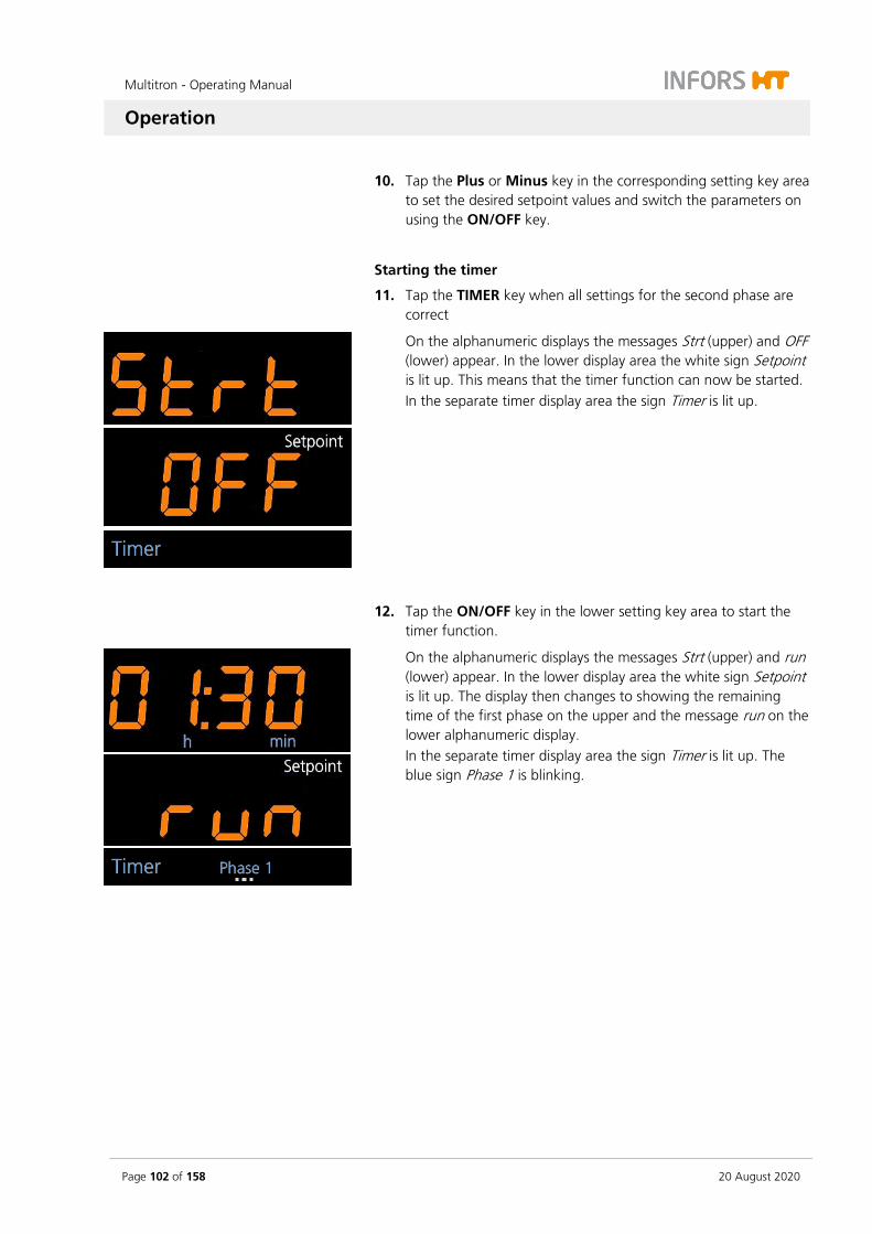
Multitron - Operating Manual
Operation
Page 102 of 158 20 August 2020
10. Tap the Plus or Minus key in the corresponding setting key area to set the desired setpoint values and switch the parameters on using the ON/OFF key.
Starting the timer
11. Tap the TIMER key when all settings for the second phase are correct
On the alphanumeric displays the messages Strt (upper) and OFF (lower) appear. In the lower display area the white sign Setpoint is lit up. This means that the timer function can now be started. In the separate timer display area the sign Timer is lit up.
12. Tap the ON/OFF key in the lower setting key area to start the timer function.
On the alphanumeric displays the messages Strt (upper) and run (lower) appear. In the lower display area the white sign Setpoint is lit up. The display then changes to showing the remaining time of the first phase on the upper and the message run on the lower alphanumeric display. In the separate timer display area the sign Timer is lit up. The blue sign Phase 1 is blinking.
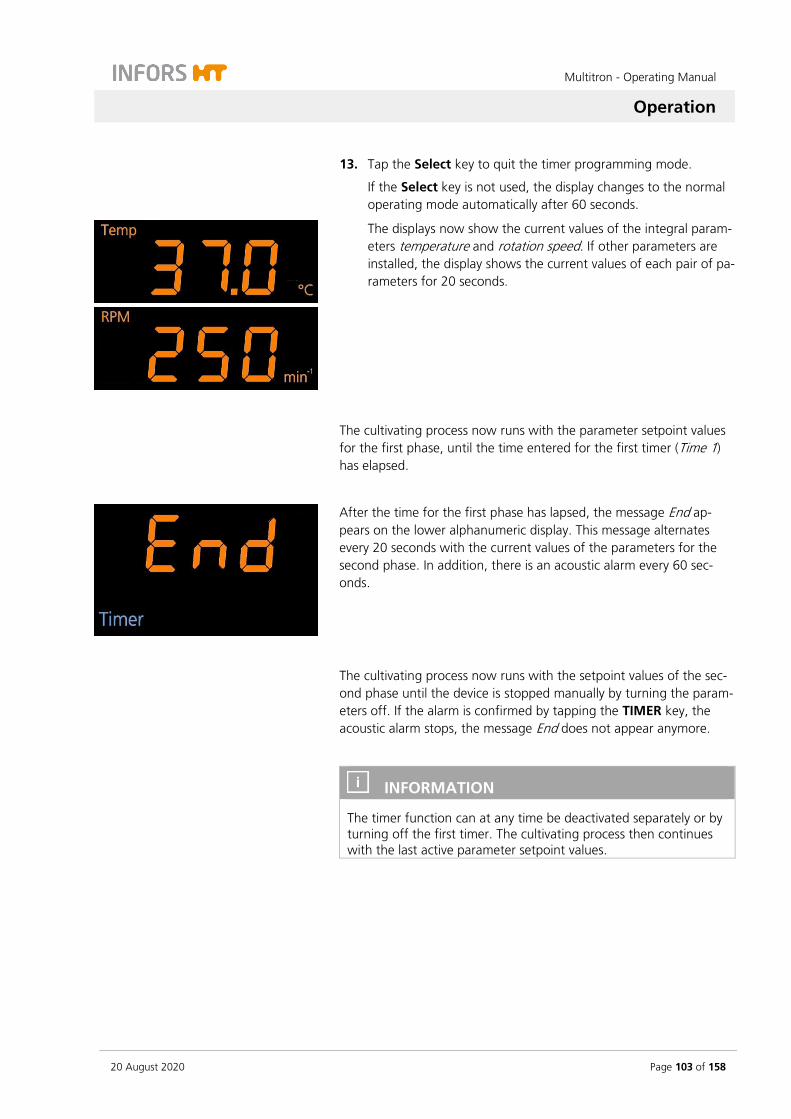
Multitron - Operating Manual
Operation
20 August 2020 Page 103 of 158
13. Tap the Select key to quit the timer programming mode.
If the Select key is not used, the display changes to the normal operating mode automatically after 60 seconds.
The displays now show the current values of the integral param-eters temperature and rotation speed. If other parameters are installed, the display shows the current values of each pair of pa-rameters for 20 seconds.
The cultivating process now runs with the parameter setpoint values for the first phase, until the time entered for the first timer (Time 1) has elapsed.
After the time for the first phase has lapsed, the message End ap-pears on the lower alphanumeric display. This message alternates every 20 seconds with the current values of the parameters for the second phase. In addition, there is an acoustic alarm every 60 sec-onds.
The cultivating process now runs with the setpoint values of the sec-ond phase until the device is stopped manually by turning the param-eters off. If the alarm is confirmed by tapping the TIMER key, the acoustic alarm stops, the message End does not appear anymore.
INFORMATION
The timer function can at any time be deactivated separately or by turning off the first timer. The cultivating process then continues with the last active parameter setpoint values.
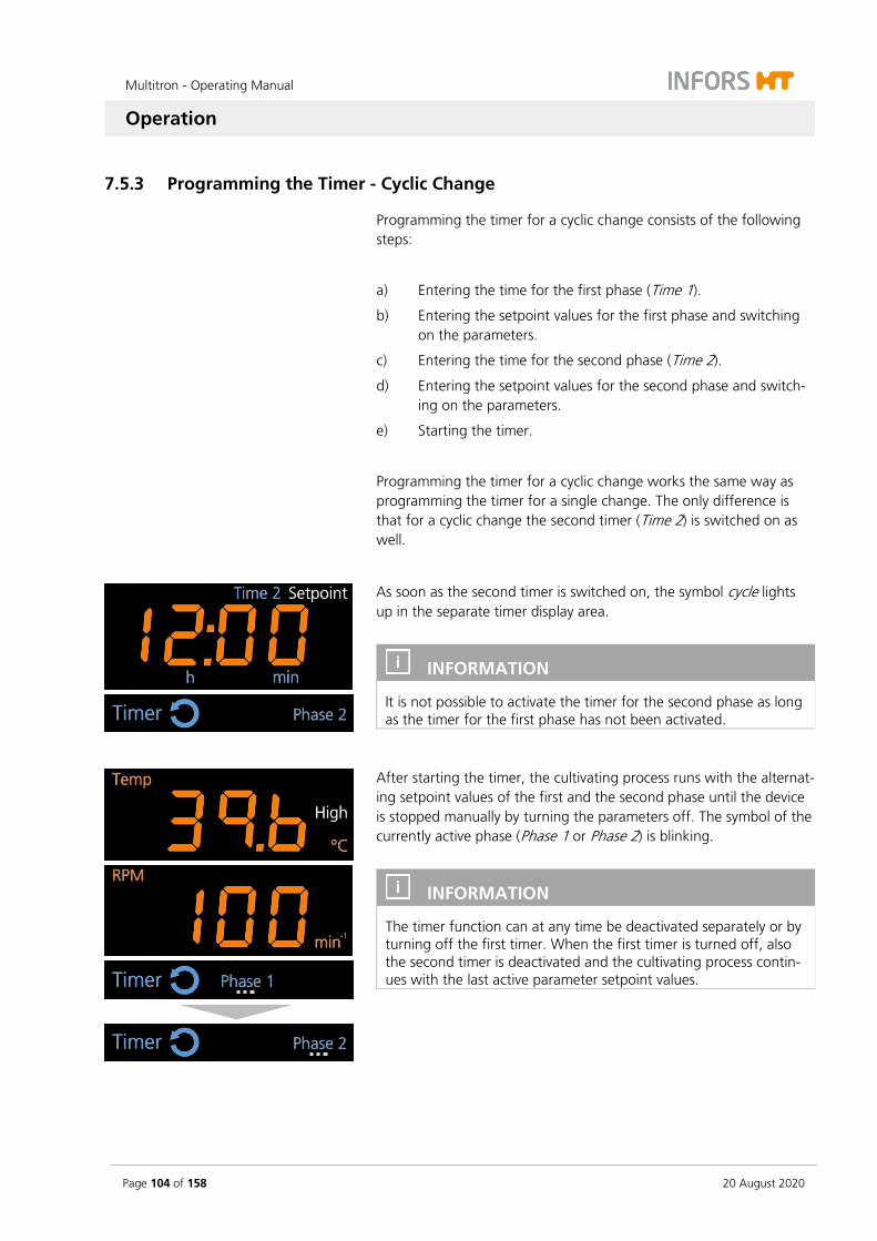
Multitron - Operating Manual
Operation
Page 104 of 158 20 August 2020
7.5.3 Programming the Timer - Cyclic Change
Programming the timer for a cyclic change consists of the following steps:
a) Entering the time for the first phase (Time 1).
b) Entering the setpoint values for the first phase and switching on the parameters.
c) Entering the time for the second phase (Time 2).
d) Entering the setpoint values for the second phase and switch-ing on the parameters.
e) Starting the timer.
Programming the timer for a cyclic change works the same way as programming the timer for a single change. The only difference is that for a cyclic change the second timer (Time 2) is switched on as well.
As soon as the second timer is switched on, the symbol cycle lights up in the separate timer display area.
INFORMATION
It is not possible to activate the timer for the second phase as long as the timer for the first phase has not been activated.
After starting the timer, the cultivating process runs with the alternat-ing setpoint values of the first and the second phase until the device is stopped manually by turning the parameters off. The symbol of the currently active phase (Phase 1 or Phase 2) is blinking.
INFORMATION
The timer function can at any time be deactivated separately or by turning off the first timer. When the first timer is turned off, also the second timer is deactivated and the cultivating process contin-ues with the last active parameter setpoint values.

Multitron - Operating Manual
Operation
20 August 2020 Page 105 of 158
7.5.4 Changing Timer Settings during Activated Timer Function
If it is required to change the duration of the time intervals, both tim-ers can be reprogrammed. To change the setting of the timers pro-ceed as follows:
Procedure 1. Tap the TIMER key to select the timer function.
2. Tap again the TIMER key to enter the timer programming mode.
On the upper alphanumeric display the setpoint value last en-tered for the time interval of the first phase (Time 1) is shown. The sign Setpoint indicates, that the time can be entered.
3. If required, tap the Plus or the Minus key in the upper setting key area to set the time for the first phase (Time 1).
INFORMATION
Do not tap the ON/OFF key after changing the timer setting, as this would turn off the timer immediately. If this happens in the cycle mode with the timer for the first phase, also the timer for the second phase is deactivated. And if acci-dentally the second timer is turned off, it cannot be activated again.
4. Tap the TIMER key to get to the time settings for the second phase (Time 2).
On the lower alphanumeric display the setpoint value last en-tered for the time interval of the second phase (Time 2) is shown. The sign Setpoint indicates, that the time can be en-tered.
5. If required, tap the Plus or the Minus key in the lower setting key area to set the time for the second phase (Time 2).
6. Tap the TIMER key again to quit the programming mode of the timer.
On the alphanumeric display the remaining time of the active phase and the message run appear.
7. Tap the Select key return to the normal operating mode of the display.
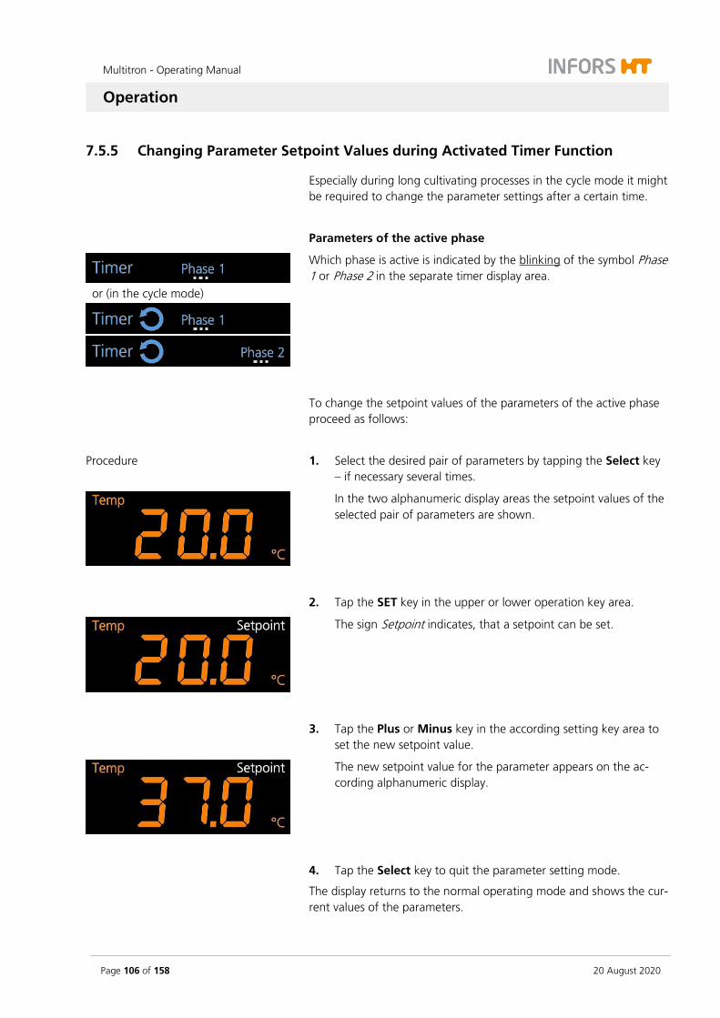
Multitron - Operating Manual
Operation
Page 106 of 158 20 August 2020
7.5.5 Changing Parameter Setpoint Values during Activated Timer Function
Especially during long cultivating processes in the cycle mode it might be required to change the parameter settings after a certain time.
Parameters of the active phase
or (in the cycle mode)
Which phase is active is indicated by the blinking of the symbol Phase 1 or Phase 2 in the separate timer display area.
To change the setpoint values of the parameters of the active phase proceed as follows:
Procedure 1. Select the desired pair of parameters by tapping the Select key – if necessary several times.
In the two alphanumeric display areas the setpoint values of the selected pair of parameters are shown.
2. Tap the SET key in the upper or lower operation key area.
The sign Setpoint indicates, that a setpoint can be set.
3. Tap the Plus or Minus key in the according setting key area to set the new setpoint value.
The new setpoint value for the parameter appears on the ac-cording alphanumeric display.
4. Tap the Select key to quit the parameter setting mode.
The display returns to the normal operating mode and shows the cur-rent values of the parameters.
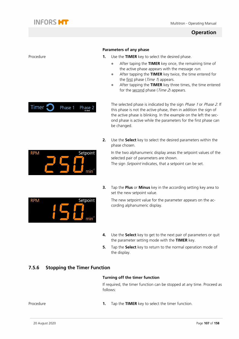
Multitron - Operating Manual
Operation
20 August 2020 Page 107 of 158
Parameters of any phase
Procedure 1. Use the TIMER key to select the desired phase.
After taping the TIMER key once, the remaining time of the active phase appears with the message run.
After tapping the TIMER key twice, the time entered for the first phase (Time 1) appears.
After tapping the TIMER key three times, the time entered for the second phase (Time 2) appears.
The selected phase is indicated by the sign Phase 1 or Phase 2. If this phase is not the active phase, then in addition the sign of the active phase is blinking. In the example on the left the sec-ond phase is active while the parameters for the first phase can be changed.
2. Use the Select key to select the desired parameters within the phase chosen.
In the two alphanumeric display areas the setpoint values of the selected pair of parameters are shown. The sign Setpoint indicates, that a setpoint can be set.
3. Tap the Plus or Minus key in the according setting key area to set the new setpoint value.
The new setpoint value for the parameter appears on the ac-cording alphanumeric display.
4. Use the Select key to get to the next pair of parameters or quit the parameter setting mode with the TIMER key.
5. Tap the Select key to return to the normal operation mode of the display.
7.5.6 Stopping the Timer Function
Turning off the timer function
If required, the timer function can be stopped at any time. Proceed as follows:
Procedure 1. Tap the TIMER key to select the timer function.
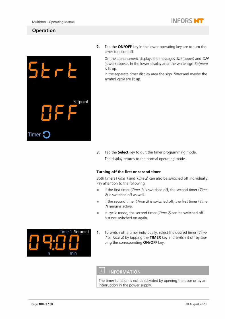
Multitron - Operating Manual
Operation
Page 108 of 158 20 August 2020
2. Tap the ON/OFF key in the lower operating key are to turn the timer function off.
On the alphanumeric displays the messages Strt (upper) and OFF (lower) appear. In the lower display area the white sign Setpoint is lit up. In the separate timer display area the sign Timer and maybe the symbol cycle are lit up.
3. Tap the Select key to quit the timer programming mode.
The display returns to the normal operating mode.
Turning off the first or second timer
Both timers (Time 1 and Time 2) can also be switched off individually. Pay attention to the following:
If the first timer (Time 1) is switched off, the second timer (Time 2) is switched off as well.
If the second timer (Time 2) is switched off, the first timer (Time 1) remains active.
In cyclic mode, the second timer (Time 2) can be switched off but not switched on again.
1. To switch off a timer individually, select the desired timer (Time 1 or Time 2) by tapping the TIMER key and switch it off by tap-ping the corresponding ON/OFF key.
INFORMATION
The timer function is not deactivated by opening the door or by an interruption in the power supply.
Multitron - Operating Manual
Operation
20 August 2020 Page 109 of 158
7.6 Using eve® to Operate the Device
INFORMATION
For detailed information on how to use eve® to operate the device, refer to the documentation supplied with eve®.
The device comes with the option of being operated from an external computer via the Ethernet interface. This requires use of the eve® platform software for bioprocesses. The Ethernet interface can be used to send or receive data. For example, setpoints can be sent to the device or parameters can be activated or deactivated. In addition, the actual values of the parameters and the values measured on the sensors as well as alarm and error messages can be transferred to eve® and thus logged.
INFORMATION
To use the Ethernet interface with other tools, a special communi-cation protocol is required. For more information, contact INFORS HT.
Points to be observed
The following points must be observed if you want to use eve® to control the device:
Via eve®, the parameters cannot be activated/deactivated manu-ally. If a permissible setpoint is sent to the device, the parameter is activated automatically. A parameter can be deactivated by sending the setpoint 0 to the device.
If the device is connected to eve®, all setpoints set in eve® are applied automatically. Any setpoints manually set on the device are overwritten.
The timer function cannot be activated via Ethernet. The timer function must be programmed and activated directly on the de-vice. Alternatively, more complex programs can be programmed comfortably using eve®.
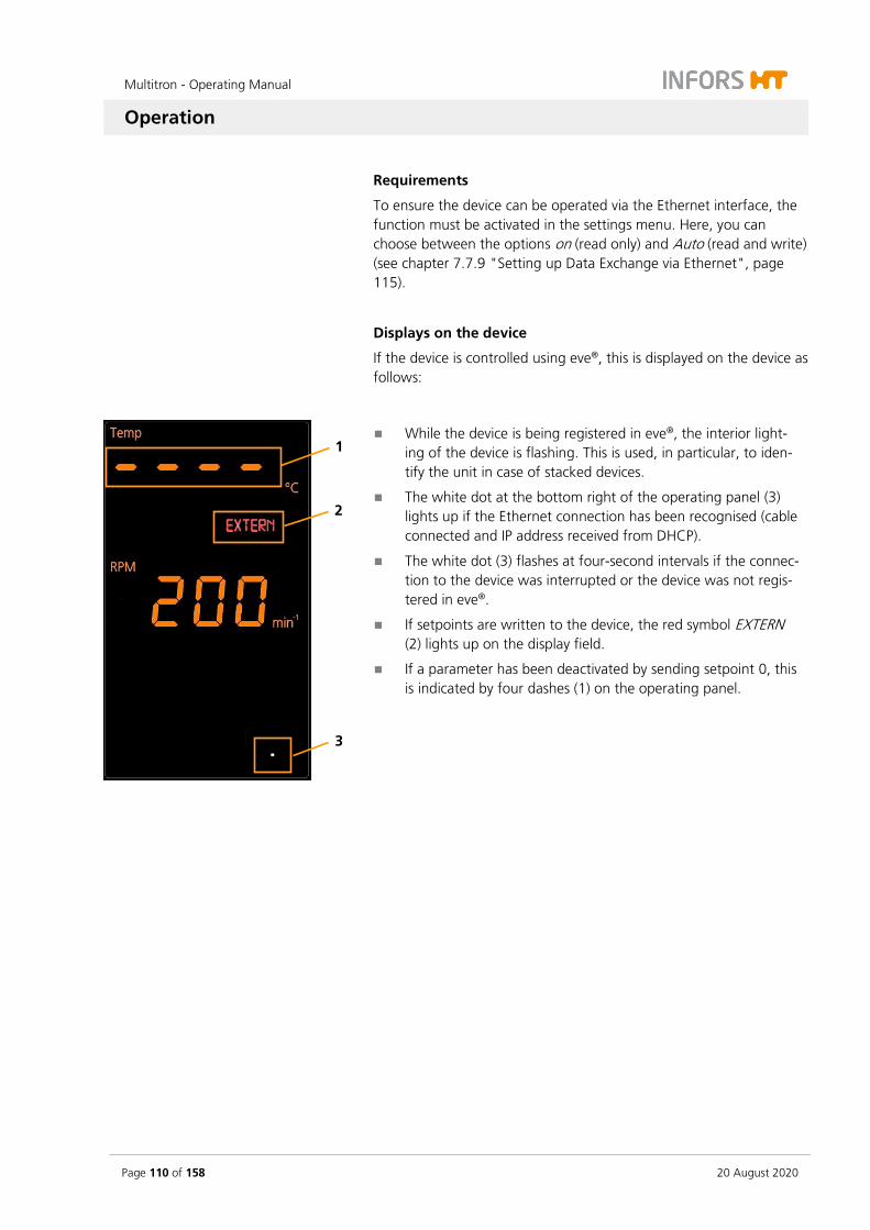
Multitron - Operating Manual
Operation
Page 110 of 158 20 August 2020
Requirements
To ensure the device can be operated via the Ethernet interface, the function must be activated in the settings menu. Here, you can choose between the options on (read only) and Auto (read and write) (see chapter 7.7.9 "Setting up Data Exchange via Ethernet", page 115).
Displays on the device
If the device is controlled using eve®, this is displayed on the device as follows:
While the device is being registered in eve®, the interior light-ing of the device is flashing. This is used, in particular, to iden-tify the unit in case of stacked devices.
The white dot at the bottom right of the operating panel (3) lights up if the Ethernet connection has been recognised (cable connected and IP address received from DHCP).
The white dot (3) flashes at four-second intervals if the connec-tion to the device was interrupted or the device was not regis-tered in eve®.
If setpoints are written to the device, the red symbol EXTERN (2) lights up on the display field.
If a parameter has been deactivated by sending setpoint 0, this is indicated by four dashes (1) on the operating panel.
1
3
2
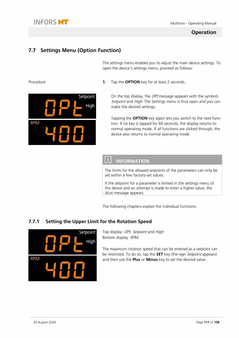
Multitron - Operating Manual
Operation
20 August 2020 Page 111 of 158
7.7 Settings Menu (Option Function)
The settings menu enables you to adjust the main device settings. To open the device’s settings menu, proceed as follows:
Procedure 1. Tap the OPTION key for at least 2 seconds.
On the top display, the OPt message appears with the symbols Setpoint and High. The Settings menu is thus open and you can make the desired settings. Tapping the OPTION key again lets you switch to the next func-tion. If no key is tapped for 60 seconds, the display returns to normal operating mode. If all functions are clicked through, the device also returns to normal operating mode.
INFORMATION
The limits for the allowed setpoints of the parameters can only be set within a few factory-set values.
If the setpoint for a parameter is limited in the settings menu of the device and an attempt is made to enter a higher value, the bLoc message appears.
The following chapters explain the individual functions.
7.7.1 Setting the Upper Limit for the Rotation Speed
Top display: OPt, Setpoint and High Bottom display: RPM The maximum rotation speed that can be entered as a setpoint can be restricted. To do so, tap the SET key (the sign Setpoint appears) and then use the Plus or Minus key to set the desired value.

Multitron - Operating Manual
Operation
Page 112 of 158 20 August 2020
7.7.2 Setting the Upper Limit for the Temperature
Top display: OPt, Temp, Setpoint and High The maximum temperature that can be entered as a setpoint can be restricted. To do so, tap the SET key (the sign Setpoint appears) and then use the Plus or Minus key to set the desired maximum temper-ature. Default value: 65 °C
7.7.3 Setting the Lower Limit for the Temperature
Top display: OPt, Temp, Setpoint and Low The minimum temperature that can be entered as a setpoint can be restricted. To do so, tap the SET key (the sign Setpoint appears) and then use the Plus or Minus key to set the desired minimum temper-ature. Default value: 4.0 °C
7.7.4 Setting the Brake Force for Stopping the Table
…
Top display: OPt Bottom display: br. 0-3 The brake force with which shaking operation is stopped when switching off the parameter rotation speed can be set in four levels. To do so, tap the SET key (the sign Setpoint appears) and then use the Plus or Minus key to set the desired brake force. The levels br. 0 to br. 3 have the following meaning:
At brake force level 0 the table is stopped by reducing the speed very slowly.
At brake force level 1 the table is also controlled but stopped a little less slowly.
At brake force level 2 a passive brake is activated by switching off the motor (factory setting).
At brake force level 3 the motor is short-circuited to stop the table as quickly as possible.
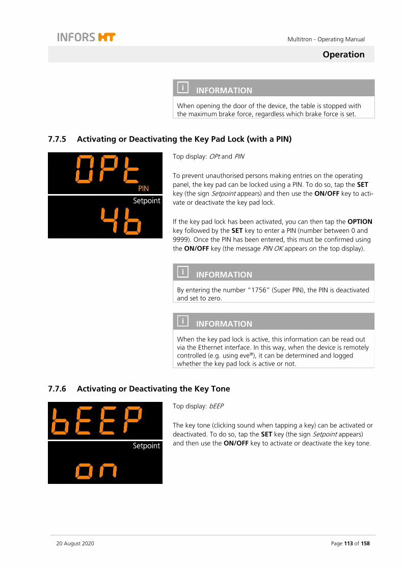
Multitron - Operating Manual
Operation
20 August 2020 Page 113 of 158
INFORMATION
When opening the door of the device, the table is stopped with the maximum brake force, regardless which brake force is set.
7.7.5 Activating or Deactivating the Key Pad Lock (with a PIN)
Top display: OPt and PIN To prevent unauthorised persons making entries on the operating panel, the key pad can be locked using a PIN. To do so, tap the SET key (the sign Setpoint appears) and then use the ON/OFF key to acti-vate or deactivate the key pad lock. If the key pad lock has been activated, you can then tap the OPTION key followed by the SET key to enter a PIN (number between 0 and 9999). Once the PIN has been entered, this must be confirmed using the ON/OFF key (the message PIN OK appears on the top display).
INFORMATION
By entering the number “1756” (Super PIN), the PIN is deactivated and set to zero.
INFORMATION
When the key pad lock is active, this information can be read out via the Ethernet interface. In this way, when the device is remotely controlled (e.g. using eve®), it can be determined and logged whether the key pad lock is active or not.
7.7.6 Activating or Deactivating the Key Tone
Top display: bEEP The key tone (clicking sound when tapping a key) can be activated or deactivated. To do so, tap the SET key (the sign Setpoint appears) and then use the ON/OFF key to activate or deactivate the key tone.
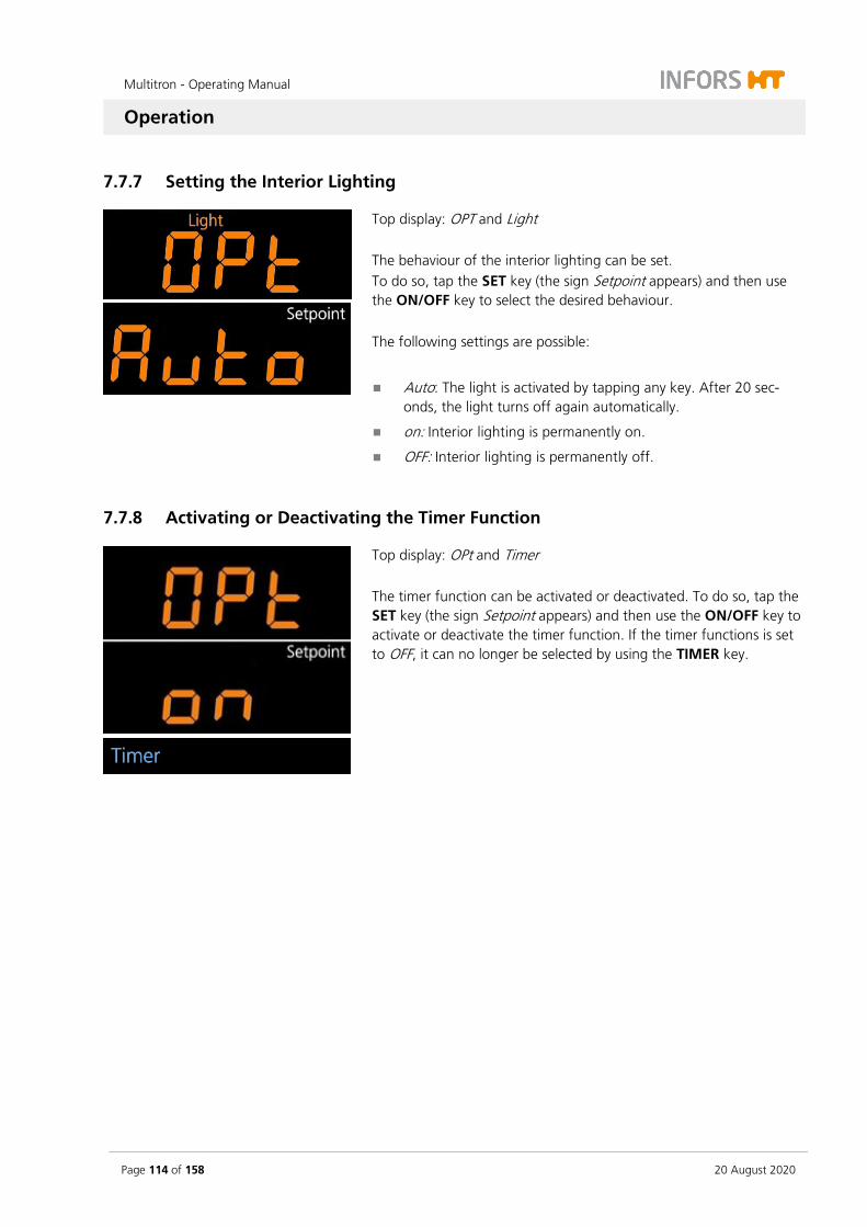
Multitron - Operating Manual
Operation
Page 114 of 158 20 August 2020
7.7.7 Setting the Interior Lighting
Top display: OPT and Light The behaviour of the interior lighting can be set. To do so, tap the SET key (the sign Setpoint appears) and then use the ON/OFF key to select the desired behaviour. The following settings are possible:
Auto: The light is activated by tapping any key. After 20 sec-onds, the light turns off again automatically.
on: Interior lighting is permanently on.
OFF: Interior lighting is permanently off.
7.7.8 Activating or Deactivating the Timer Function
Top display: OPt and Timer The timer function can be activated or deactivated. To do so, tap the SET key (the sign Setpoint appears) and then use the ON/OFF key to activate or deactivate the timer function. If the timer functions is set to OFF, it can no longer be selected by using the TIMER key.

Multitron - Operating Manual
Operation
20 August 2020 Page 115 of 158
7.7.9 Setting up Data Exchange via Ethernet
Top display: OPt, EXTERN and Wireless You can set whether and in which direction data can be sent via the Ethernet interface. To do so, tap the SET key (the writing Setpoint appears) and then use the ON/OFF key to select the desired setting. The following settings are possible:
Auto: Send and receive data, i.e. information from the device can be recorded but commands can also be sent to the device (e.g. changes to the parameters).
on: Only receive data, i.e. only data sent from the device can be recorded.
OFF: The Ethernet interface is deactivated; no communication can take place.
7.7.10 Setting the Height Above Sea Level (Altimeter)
Top display: ALti and CO2
The digital CO2 sensor GMP251 is pressure-dependent. To achieve precise measuring results, the altitude of the device’s location can be entered. To do so, tap the SET key (the sign Setpoint appears) and then use the Plus or Minus key to set the altitude in meters. Default value: 0
7.7.11 Activating or Deactivating the Door Alarm
Top display: doAL The device has a door alarm. This is triggered if the door is left open for too long. To activate or deactivate the door alarm, tap the SET key (the sign Setpoint appears) and then use the ON/OFF key. The time after which the alarm is triggered can be set. To do so, tap the SET key again (the sign Setpoint appears) and then use the Plus or Minus key to set the desired time period (1-10 minutes).

Multitron - Operating Manual
Operation
Page 116 of 158 20 August 2020
7.7.12 Humidity – Switch On/Off High Alarm
Top display: OPt and ALARM Bottom display: Humid and High The High alarm of the Humidity parameter can be switched on or off. If the alarm is switched off, no alarm is triggered if the humidity ex-ceeds the upper limit value. Since the humidity in the incubation chamber is normally not a critical parameter that has a direct impact on the success of the cultivation, the High alarm of the Humidity pa-rameter is switched off ex factory. To switch on or off the High alarm of the Humidity parameter, tap the SET key (the sign Setpoint appears) and then use the ON/OFF key to activate or deactivate the alarm.
7.8 Setting the Adjustable Throw
INFORMATION
Improper modification of the throw of a device with an adjustable throw represents a safety risk. The throw may therefore only be changed by personnel that has received appropriate training and authorisations. If you have any questions, contact your local IN-FORS HT representative (see contact details on page 2).

Multitron - Operating Manual
Operation
20 August 2020 Page 117 of 158
7.9 Switching Off the Device
ATTENTION
Parameters, that have not been switched off prior to switching off the device, are automatically activated when the device is switched on. This can lead to damages to the device and cultivation vessels.
Always switch off all parameters before switching off the device.
INFORMATION
The parameter setpoints remain stored for approximately one month.
To switch off the device, proceed as follows:
Procedure 1. Switch off all parameters. Make sure that, in addition to the ro-tation speed, parameters that are not visible, such as tempera-ture, humidity or CO2, are also switched off.
2. Switch off the device by pressing the power switch.
3. If you do not intend to use the device for a long time, discon-nect the device from the power supply.
7.10 Behaviour in Case of Interrupted Power Supply
If the power supply to the device is interrupted during a running cul-tivation process (e.g. by flicking the power switch or in case of a power failure), all parameters and timer setpoints as well as the resid-ual time of the last active timer phase are stored.
If power supply is restored, the device restarts automatically with the last stored setpoints. If a timer was active prior to the interruption to power supply, the device restarts with the residual time of the last active phase and the setpoints stored for this phase.
As a warning, the word RESTARTED and the warning icon flash on the display field with the warning and alarm messages. The RESTARTED message can be confirmed by tapping any key and then disappears.

Multitron - Operating Manual
Rectifying Faults
Page 118 of 158 20 August 2020
8 Rectifying Faults
The following section describes possible reasons for faults and how to rectify them.
Fault messages
A distinction is made between alarms (ALARM) and error messages (ERROR):
Alarms refer to errors in the process, for example, when the actual parameter values deviate from the setpoints. Alarms are indicated with the warning symbol and an acoustic signal. The alarm message can be confirmed by tapping any key. If an alarm is not confirmed manually, it disappears as soon as the condition, that has triggered the alarm, is not fulfilled any-more.
Error messages relate to technical faults in the device. The af-fected functions are stopped automatically. Error messages are indicated with the warning symbol and an acoustic signal. The error can be confirmed by tapping the Select key.
Contact the manufacturer in case of faults that cannot be resolved by following the instructions below. For service contact details, see page 2.

Multitron - Operating Manual
Rectifying Faults
20 August 2020 Page 119 of 158
8.1 Alarm Messages
8.1.1 Parameter Alarms (High / Low)
A parameter alarm is triggered if the actual value of a parameter de-viates too much from the setpoint after a specified waiting time. In the example on the left the temperature is too high. The maximum allowed deviation from the setpoint and the waiting time are factory-set and cannot be changed.
INFORMATION
An alarm is only triggered if the actual value of the parameter does not change for a certain period. If there is a fluctuation, the counter for triggering the alarm is reset.
Alarm Meaning Deviation from setpoint
Waiting time
Temp High / Low Temperature too high/low > ± 1 °C 20 min (18 °C to 40 °C)
75 min (< 18 °C / > 40 °C)
RPM High / Low Rotation speed too high/low > ± 10 min-1 2 min
CO2 High / Low CO2 concentration too high/low > ± 0.5 % 15 min
Humid High / Low Humidity too high/low > ± 5 % 15 min
Note: The Humid High alarm is deactivated by default. If required, the alarm can be switched on in the settings menu (see chapter 7.7.12, page 116).
INFORMATION
If the setpoint for a parameter is limited in the settings menu of the device and an attempt is made to enter higher value, the bLoc message appears.
8.1.2 Alarm Message RESTARTED
The alarm message RESTARTED appears if the device has switched it-self back on based on the stored parameters after a power failure. After power is restored, the device automatically restarts with the same parameters to avoid damage to the cultures due to an uninten-tional termination of the process. The alarm message indicates that the process has been interrupted. However, it is not possible to deter-mine how long the interruption lasted.
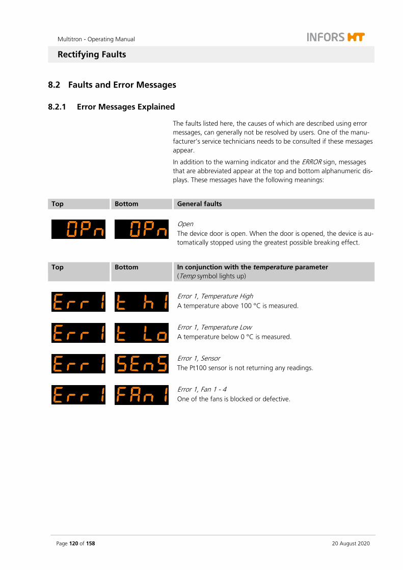
Multitron - Operating Manual
Rectifying Faults
Page 120 of 158 20 August 2020
8.2 Faults and Error Messages
8.2.1 Error Messages Explained
The faults listed here, the causes of which are described using error messages, can generally not be resolved by users. One of the manu-facturer’s service technicians needs to be consulted if these messages appear.
In addition to the warning indicator and the ERROR sign, messages that are abbreviated appear at the top and bottom alphanumeric dis-plays. These messages have the following meanings:
Top Bottom General faults
Open The device door is open. When the door is opened, the device is au-tomatically stopped using the greatest possible breaking effect.
Top Bottom In conjunction with the temperature parameter (Temp symbol lights up)
Error 1, Temperature High A temperature above 100 °C is measured.
Error 1, Temperature Low A temperature below 0 °C is measured.
Error 1, Sensor The Pt100 sensor is not returning any readings.
Error 1, Fan 1 - 4 One of the fans is blocked or defective.
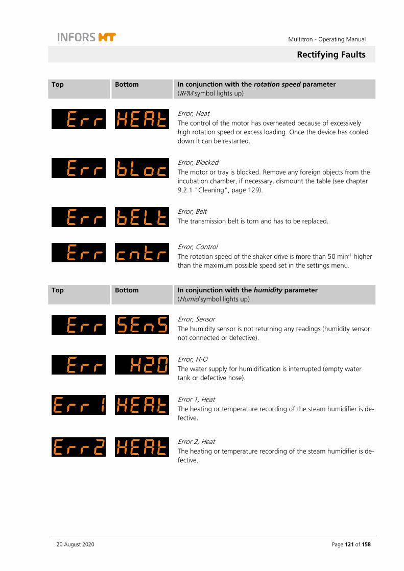
Multitron - Operating Manual
Rectifying Faults
20 August 2020 Page 121 of 158
Top Bottom In conjunction with the rotation speed parameter (RPM symbol lights up)
Error, Heat The control of the motor has overheated because of excessively high rotation speed or excess loading. Once the device has cooled down it can be restarted.
Error, Blocked The motor or tray is blocked. Remove any foreign objects from the incubation chamber, if necessary, dismount the table (see chapter 9.2.1 "Cleaning", page 129).
Error, Belt The transmission belt is torn and has to be replaced.
Error, Control The rotation speed of the shaker drive is more than 50 min-1 higher than the maximum possible speed set in the settings menu.
Top Bottom In conjunction with the humidity parameter (Humid symbol lights up)
Error, Sensor The humidity sensor is not returning any readings (humidity sensor not connected or defective).
Error, H2O The water supply for humidification is interrupted (empty water tank or defective hose).
Error 1, Heat The heating or temperature recording of the steam humidifier is de-fective.
Error 2, Heat The heating or temperature recording of the steam humidifier is de-fective.
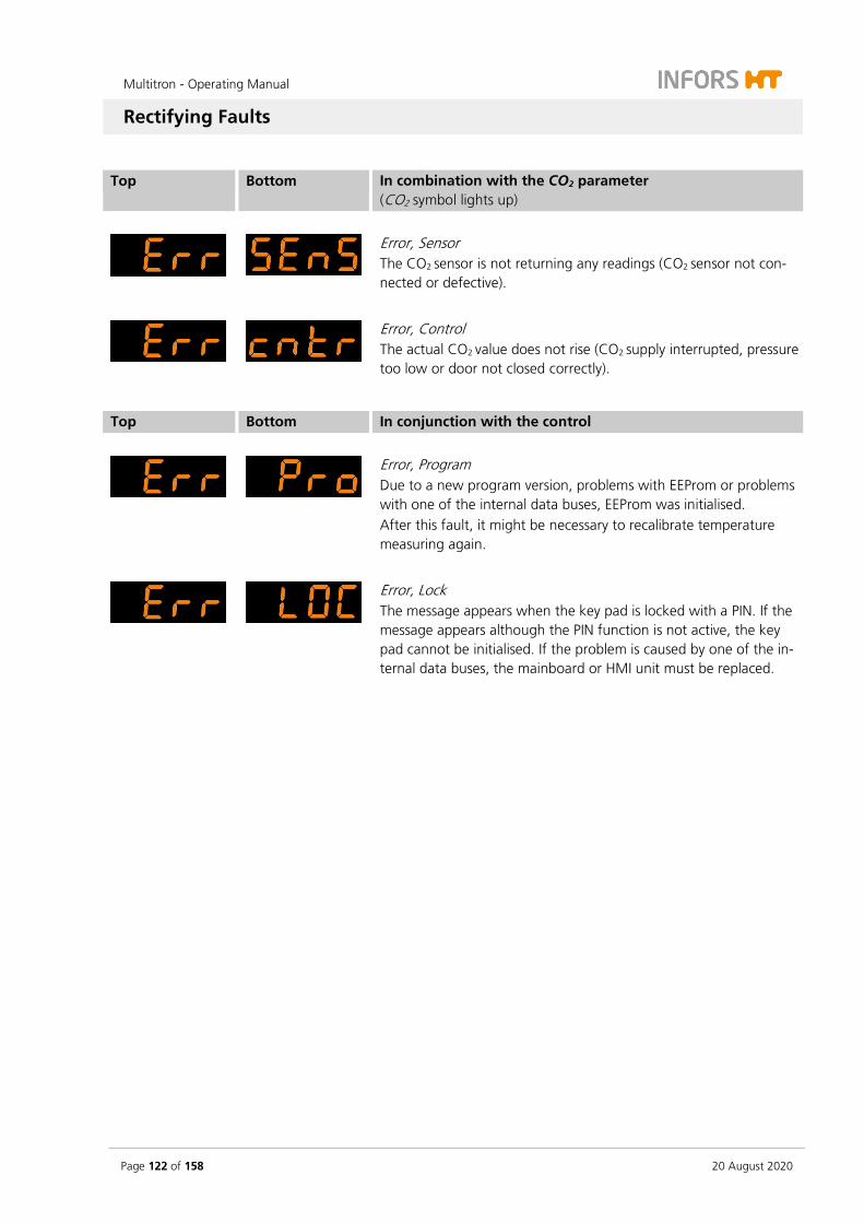
Multitron - Operating Manual
Rectifying Faults
Page 122 of 158 20 August 2020
Top Bottom In combination with the CO2 parameter (CO2 symbol lights up)
Error, Sensor The CO2 sensor is not returning any readings (CO2 sensor not con-nected or defective).
Error, Control The actual CO2 value does not rise (CO2 supply interrupted, pressure too low or door not closed correctly).
Top Bottom In conjunction with the control
Error, Program Due to a new program version, problems with EEProm or problems with one of the internal data buses, EEProm was initialised. After this fault, it might be necessary to recalibrate temperature measuring again.
Error, Lock The message appears when the key pad is locked with a PIN. If the message appears although the PIN function is not active, the key pad cannot be initialised. If the problem is caused by one of the in-ternal data buses, the mainboard or HMI unit must be replaced.

Multitron - Operating Manual
Rectifying Faults
20 August 2020 Page 123 of 158
8.2.2 Fault Tables
The following tables describe possible faults for which usually no er-ror message appears on the display and for which no alarm is sounded, a few exceptions aside. In many cases operators can resolve these themselves.
General faults
Fault
After activating the power switch, the display and the power switch do not light up.
Possible cause Measures Personnel
Power supply of the device is interrupted.
Check if the plugs are plugged in correctly.
Check the mains connection.
Operator
The fuse of the device (230 V version) is defective or the ther-mal protection switch (115 V version) was triggered.
Change the fuse respectively reset the thermal pro-tection switch (see chapter 8.3, page 127). If the fault occurs more than once, contact your local IN-FORS HT representative.
Operator
Fault
The tray cannot be locked.
Possible cause Measures Personnel
The tray is blocked by foreign objects.
Remove foreign objects from the table. Operator
The tray is bent. Replace the tray. Operator
Fault
The interior lighting does not work.
Possible cause Measures Personnel
Interior lighting is deactivated. Activate interior lighting (see chapter 7.7.7, page 114).
Operator
The LED unit of the interior lighting is defective.
Contact your local INFORS HT representative. INFORS HT service tech-nician or licenced dealer
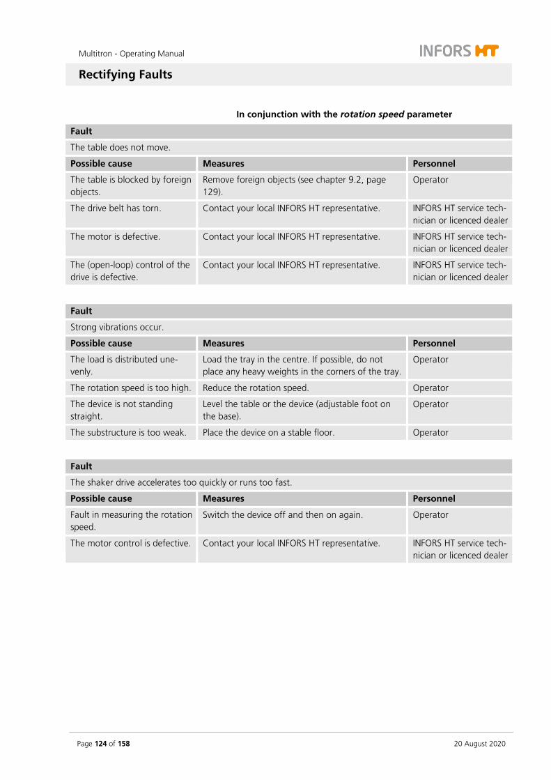
Multitron - Operating Manual
Rectifying Faults
Page 124 of 158 20 August 2020
In conjunction with the rotation speed parameter
Fault
The table does not move.
Possible cause Measures Personnel
The table is blocked by foreign objects.
Remove foreign objects (see chapter 9.2, page 129).
Operator
The drive belt has torn. Contact your local INFORS HT representative. INFORS HT service tech-nician or licenced dealer
The motor is defective. Contact your local INFORS HT representative. INFORS HT service tech-nician or licenced dealer
The (open-loop) control of the drive is defective.
Contact your local INFORS HT representative. INFORS HT service tech-nician or licenced dealer
Fault
Strong vibrations occur.
Possible cause Measures Personnel
The load is distributed une-venly.
Load the tray in the centre. If possible, do not place any heavy weights in the corners of the tray.
Operator
The rotation speed is too high. Reduce the rotation speed. Operator
The device is not standing straight.
Level the table or the device (adjustable foot on the base).
Operator
The substructure is too weak. Place the device on a stable floor. Operator
Fault
The shaker drive accelerates too quickly or runs too fast.
Possible cause Measures Personnel
Fault in measuring the rotation speed.
Switch the device off and then on again. Operator
The motor control is defective. Contact your local INFORS HT representative. INFORS HT service tech-nician or licenced dealer

Multitron - Operating Manual
Rectifying Faults
20 August 2020 Page 125 of 158
Faults in conjunction with the temperature parameter
Fault
Temperature too high compared to setpoint.
Possible cause Measures Personnel
Fault in temperature measur-ing.
Check if the Pt100 sensor works. In case of a de-fect, contact your local INFORS HT representative.
Operator
Internal or external cooling unit is not switched on.
Switch on cooling. Operator
No cooling available and differ-ence between setpoint value and ambient temperature too small.
Increase the setpoint value or equip the device with a cooling.
Operator
Fault
The temperature does not reach the desired setpoint.
Possible cause Measures Personnel
The heating is not switched on. Activate the temperature parameter. Operator
The setpoint is set too low. Raise setpoint. Operator
The ambient temperature does not meet the requirements.
Check the ambient temperature and correct it if necessary (see chapter 6.1, page 72
Operator
Door not closed completely. Close door completely. Operator
The heating fans do not work. Contact your local INFORS HT representative. INFORS HT service tech-nician or licenced dealer
INFORMATION
The re-measuring of the temperature only provides reliable infor-mation when calibrated measuring tools are used and only if they are used at points specified by INFORS HT. A measurement at un-defined positions in the casing will not produce any usable data.
For information about temperature measuring, contact your local INFORS HT representative or request a quote for calibrating the pa-rameters.

Multitron - Operating Manual
Rectifying Faults
Page 126 of 158 20 August 2020
Faults in conjunction with the CO2 parameter
Fault
CO2 concentration too low (deviation > 1%).
Possible cause Measures Personnel
CO2 bottle empty. Install new CO2 bottle. Operator
Inlet pressure or flow too low. Increase inlet pressure or flow. Operator
CO2 valve closed or blocked. Contact your local INFORS HT branch. INFORS HT service tech-nician or licenced dealer
Fault
CO2 concentration too high (deviation < 1%).
Possible cause Measures Personnel
CO2 input pressure too high. Reduce input pressure. Operator
Fault
CO2 value fluctuates, actual value is not constant.
Possible cause Measures Personnel
Inlet pressure or flow too high. Decrease inlet pressure or flow. Operator
Faults in conjunction with the humidity parameter
Fault
The water supply for humidification is interrupted.
Possible cause Measures Personnel
The water container is empty. Top up the water container. Operator
Air trapped between wet filter and reservoir.
Replace the wet filter with a dry one. Operator
Valve defective. Contact your local INFORS HT branch. INFORS HT service tech-nician or licenced dealer
Fault
The humidity parameter was deactivated automatically.
Possible cause Measures Personnel
Transfer error of the humidity sensor or temperature sensor.
Restart software (switch the device off and then on again).
Operator
Inlet pressure is too high. Reduce inlet pressure (max. 0.3 bar). Operator
Steam generator is defective. Contact your local INFORS HT representative. INFORS HT service tech-nician or licenced dealer

Multitron - Operating Manual
Rectifying Faults
20 August 2020 Page 127 of 158
8.3 Replacing Fuses
INFORMATION
The fuses may only be replaced by fuses of the same rating. For in-formation concerning the requirements for the fuses see chapter 12.3 "Specifications of the Basic Unit", page 140.
To replace a defective fuse, proceed as follows:
Procedure 1. Turn off the device and pull out the mains plug.
2. Unlock the plug for the fuses by pressing together the two flaps and pull out the plug at the same time.
3. Remove the defective fuse.
4. Insert a new fuse with the correct number of Amperes.
5. Push the plug as far back in the opening as possible until it snaps in.
6. Re-establish the power supply to the device.
8.4 Returning for Repair
The provider must return the device or the faulty component part(s) to the manufacturer if, after consulting the service department of the local dealer or the manufacturer, on-site diagnosis and/or repair is not possible.
INFORMATION
When returning the device, the component part or accessory for repair, it is required for the safety of all parties involved and be-cause of legal provisions that a lawful declaration of decontamina-tion is present. Refer to main chapter “Safety and Responsibility”, chapter “Declaration of Contamination” for details.
Multitron - Operating Manual
Maintenance and Cleaning
Page 128 of 158 20 August 2020
9 Maintenance and Cleaning
WARNING
To prevent life-threatening electric shocks, always switch off the device and disconnect it from the power supply before carrying out any maintenance or cleaning.
9.1 Maintenance
The device requires hardly any maintenance. This reduces the running costs to certain regular checks and cleaning. The following table de-scribes the maintenance work that is required to ensure optimum, fault-free operation.
If increased wear is detected during the regular checks, the required maintenance intervals must be reduced to suit with the actual signs of wear. Keep in mind that various media or gases will have more or less corrosive effects on the metal parts. When using particularly ag-gressive substances, more frequent checks are required in order to maintain smooth device operation.
Contact the manufacturer if you have any questions regarding maintenance work or intervals; see Service contact details on page 2.
Interval Maintenance work To be carried out by
Prior to each use Check hoses and power cable for damage; replace if necessary. Operator
Check that hoses (water, CO2) are connected tightly. Operator
Check all seals on the device, especially on the door, and replace if necessary.
Qualified techni-cians
Check whether the interior lighting works, have lamps replaced if nec-essary.
Qualified techni-cians
After each use Clean the device, if necessary, disinfect thoroughly. Operator
Annually If you are using humidity and CO2 sensors, have these calibrated at least once a year to ensure measuring results remain accurate.
Qualified techni-cians
Multitron - Operating Manual
Maintenance and Cleaning
20 August 2020 Page 129 of 158
9.2 Cleaning and Disinfection
If substances, in particular hazardous substances, are spilled in or on the device, the device has to be cleaned and disinfected thoroughly. Furthermore, the device should be cleaned and disinfected on a regu-lar basis to ensure proper operation.
If there are doubts concerning the compatibility of cleaning and disin-fection agents, contact your local INFORS HT representative (see ser-vice contact details on page 2).
ATTENTION
Insufficient cleaning and disinfection can lead to damage to cul-tures due to contamination.
9.2.1 Cleaning
Detergent
Mild detergents, e.g. dishwashing liquid or neutral cleaning agents, are suitable for all surfaces:
Exterior surfaces of the casing
Front window
Interior surfaces of the casing (incl. base tray)
Steel plate covers
Table
Trays (incl. clamps and other holders)
ATTENTION
Aggressive cleaning agents, solvents and abrasive cleaning utensils (hard sponges, brushes) can scratch surfaces, damage the device and impair its function.
Notices on cleaning
To clean the surfaces, use a soft cloth, ideally lint-free. This applies in particular to the front window. Disinfect using commercially available disinfectant if necessary.

Multitron - Operating Manual
Maintenance and Cleaning
Page 130 of 158 20 August 2020
Splashing water
Always use a wet cloth when cleaning the base tray; never pour wa-ter into the tray. Make sure that no water splashes into the bearings.
After cleaning the device, especially the interior and the base tray, dry it with a cloth.
Dust
Over time, dust can collect in the vents and on other exposed parts. It can be removed carefully using a vacuum cleaner.
Installing/dismantling the table
In order to allow cleaning of the base tray in case of glass breakages or soiling caused by culture liquids, the table can be detached from the counterweight and folded up. To do so, proceed as follows:
CAUTION
After being folded up, the table must be held in position by hand. If the table is not secured properly, there is a risk of it folding back down again. This can cause injuries.
– If possible, have a second person hold the table in place once it has been folded up. Alternatively, you can place an object under the table to stop it from folding back down.
– Proceed with caution when folding the table back down.
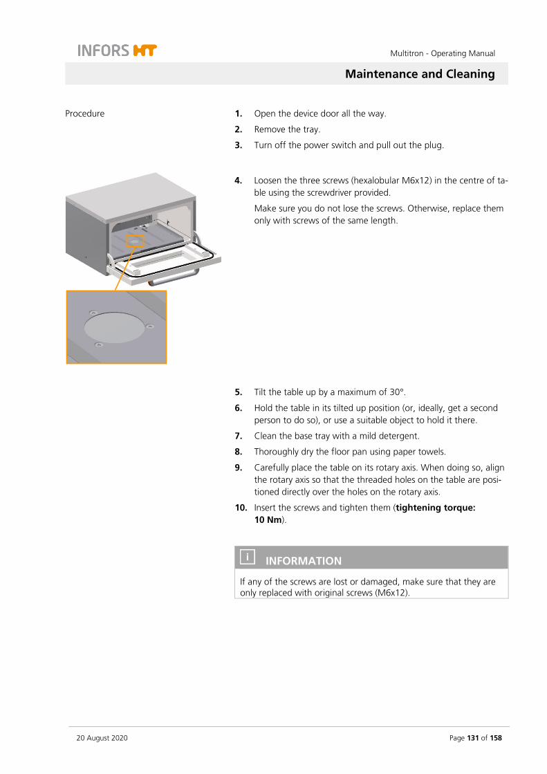
Multitron - Operating Manual
Maintenance and Cleaning
20 August 2020 Page 131 of 158
Procedure 1. Open the device door all the way.
2. Remove the tray.
3. Turn off the power switch and pull out the plug.
4. Loosen the three screws (hexalobular M6x12) in the centre of ta-ble using the screwdriver provided.
Make sure you do not lose the screws. Otherwise, replace them only with screws of the same length.
5. Tilt the table up by a maximum of 30°.
6. Hold the table in its tilted up position (or, ideally, get a second person to do so), or use a suitable object to hold it there.
7. Clean the base tray with a mild detergent.
8. Thoroughly dry the floor pan using paper towels.
9. Carefully place the table on its rotary axis. When doing so, align the rotary axis so that the threaded holes on the table are posi-tioned directly over the holes on the rotary axis.
10. Insert the screws and tighten them (tightening torque: 10 Nm).
INFORMATION
If any of the screws are lost or damaged, make sure that they are only replaced with original screws (M6x12).
Multitron - Operating Manual
Maintenance and Cleaning
Page 132 of 158 20 August 2020
9.2.2 Disinfection
Only use quaternary ammonium compounds for wipe-down disinfec-tion. As a tried as tested disinfectant, we recommend Fermacidal D2.
ATTENTION
Heat (temperatures above 80 °C), aggressive disinfectants such as chlorine bleach and UVC radiation can damage the device and sig-nificantly limit the function and useful life of the machine.
We recommend against using UV lamps for disinfection of the de-vice because the UV rays can massively damage the plastic casing in case of multiple applications.
For information about the procedure for disinfection underneath the table, in particular removing and mounting the table, see chapter 9.2.1 "Cleaning", page 129.
Multitron - Operating Manual
Transport and Storage
20 August 2020 Page 133 of 158
10 Transport and Storage
The inbound delivery and transport to the assembly location are per-formed only by INFORS HT employees or by persons authorised by INFORS HT.
Nonetheless it is possible that the provider’s personnel is entrusted with transport tasks in the context of on-site transport. In this case, observe the following notes.
10.1 Transport
WARNING
Improper transport, the use of incorrect auxiliary equipment and careless handling of the device may lead to injuries and severe property damage.
When transporting the device, observe the following:
Prior to moving the device, transport fasteners (rubber wedges) must be inserted to prevent uncontrolled movements of the ta-ble.
Always work in pairs and use suitable auxiliary equipment when transporting the unit.
Especially when using auxiliary tools, it is important to keep in mind that the device’s centre of gravity is not in the middle.
10.2 Storage
Decontaminate, thoroughly clean and dry the device every time before placing it in storage. Maintain and store sensors pro-duced by other manufacturers in accordance with their instruc-tions.
Store the device and its components clean, dry and protected against dust, dirt and liquids.
Store the device and its components in a cool place with low humidity but protected against frost.
Storage temperature: 10 °C to 35 °C. Relative humidity, non-condensing: 10 % to 85 %.
Protect the device from aggressive media, direct sunlight and vibrations.
Multitron - Operating Manual
Disassembly and Disposal
Page 134 of 158 20 August 2020
11 Disassembly and Disposal
The device must be disassembled and disposed of in an environmen-tally friendly manner if it is no longer in use.
INFORMATION
When returning the device for disassembly or disposal, it is re-quired for the safety of all parties involved and because of legal provisions that a lawful declaration of decontamination is present. Refer to main chapter “Safety and Responsibility”, chapter “Decla-ration of Contamination” for details.
11.1 Disassembly
Prior to disassembly:
Switch off the device and lock any isolation switch in the ‘off’ position.
Physically disconnect the main energy supply from the device and wait for components to fully discharge.
Remove and dispose of all additional consumable items, auxiliary components and/or spent processing material in an environmen-tally acceptable manner.
Clean and disassemble component parts professionally with regard to any local regulations concerning employment and environmental pro-tection. If possible, separate materials.
Multitron - Operating Manual
Disassembly and Disposal
20 August 2020 Page 135 of 158
11.2 Disposal
Recycle disassembled components if no agreement is made concern-ing reclaim or disposal.
Send metals for scrap.
Send plastic components for recycling.
Sort and dispose of the remaining components according their material composition.
WARNING
Electronic waste, electronic components, lubricants or other auxil-iary materials/supplies are subject to hazardous waste regulations and may only be disposed of by registered specialist disposal firms.
For disposal, the system units are to be disassembled and dismantled into individual material groups. These materials are to be disposed of according to the applicable national and local legislation.
Local authorities or specialist disposal firms can provide information regarding environmentally acceptable disposal.
If no special arrangements have been made for return, INFORS HT units with the required declaration of decontamination can be sent back to the manufacturer for disposal.

Multitron - Operating Manual
Technical Data and Specifications
Page 136 of 158 20 August 2020
12 Technical Data and Specifications
12.1 Dimension Drawings
Two units stacked with high base frame and the following options:
Low cover (1)
CO2 control (2)
Analog output (3)
Direct steam humidification (4)
4
3
2
1

Multitron - Operating Manual
Technical Data and Specifications
20 August 2020 Page 137 of 158
Three units stacked with low base frame and the following options:
Top cooling (1)
CO2 control (2)
Analog output (3)
Direct steam humidification (4)
All dimensions in mm
2
1
3
4
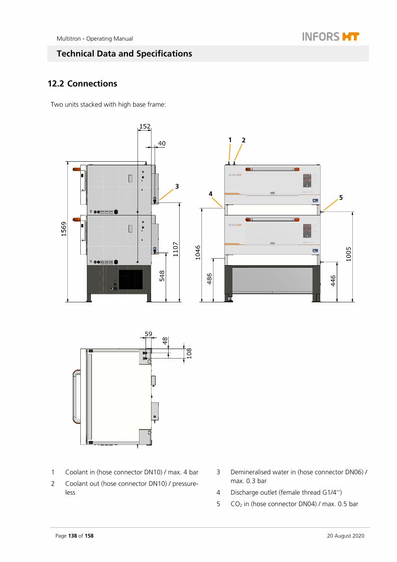
Multitron - Operating Manual
Technical Data and Specifications
Page 138 of 158 20 August 2020
12.2 Connections
Two units stacked with high base frame:
1 Coolant in (hose connector DN10) / max. 4 bar
2 Coolant out (hose connector DN10) / pressure-less
3 Demineralised water in (hose connector DN06) / max. 0.3 bar
4 Discharge outlet (female thread G1/4‘‘)
5 CO2 in (hose connector DN04) / max. 0.5 bar
2 1
3
5 4

Multitron - Operating Manual
Technical Data and Specifications
20 August 2020 Page 139 of 158
Three units stacked with low base frame:
All dimensions in mm

Multitron - Operating Manual
Technical Data and Specifications
Page 140 of 158 20 August 2020
12.3 Specifications of the Basic Unit
12.3.1 Weight and Dimensions
Weight
Description Value Unit
Single unit (3 mm throw) 129 kg
Single unit (25 mm throw) 137 kg
Single unit (50 mm throw) 144 kg
Single unit (adjustable throw) 143 kg
Base frame 13 cm 26 kg
Base frame 41 cm 45 kg
Exterior dimensions single unit
Description Value Unit
Width 1070 mm
Depth (Door closed) 880 mm
Depth (Door open) 1165 mm
Height (with base frame 13 cm) 695 mm
Height (with base frame 41 cm) 975 mm
Exterior dimensions two units stacked
Description Value Unit
Width 1070 mm
Depth (Door closed) 880 mm
Height (with base frame 13 cm) 1255 mm
Height (with base frame 41 cm) 1535 mm
Exterior dimensions three units stacked
Description Value Unit
Width 1070 mm
Depth (Door closed) 880 mm
Height (with base frame 13 cm) 1850 mm
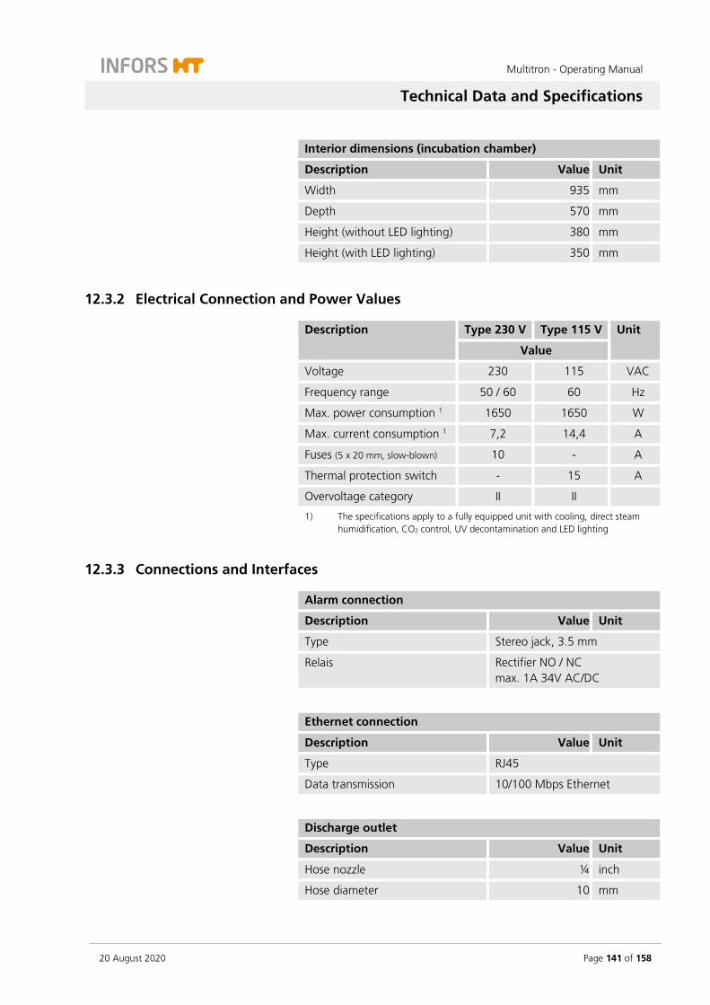
Multitron - Operating Manual
Technical Data and Specifications
20 August 2020 Page 141 of 158
Interior dimensions (incubation chamber)
Description Value Unit
Width 935 mm
Depth 570 mm
Height (without LED lighting) 380 mm
Height (with LED lighting) 350 mm
12.3.2 Electrical Connection and Power Values
Description Type 230 V Type 115 V Unit
Value
Voltage 230 115 VAC
Frequency range 50 / 60 60 Hz
Max. power consumption 1 1650 1650 W
Max. current consumption 1 7,2 14,4 A
Fuses (5 x 20 mm, slow-blown) 10 - A
Thermal protection switch - 15 A
Overvoltage category II II
1) The specifications apply to a fully equipped unit with cooling, direct steam humidification, CO2 control, UV decontamination and LED lighting
12.3.3 Connections and Interfaces
Alarm connection
Description Value Unit
Type Stereo jack, 3.5 mm
Relais Rectifier NO / NC max. 1A 34V AC/DC
Ethernet connection
Description Value Unit
Type RJ45
Data transmission 10/100 Mbps Ethernet
Discharge outlet
Description Value Unit
Hose nozzle ¼ inch
Hose diameter 10 mm

Multitron - Operating Manual
Technical Data and Specifications
Page 142 of 158 20 August 2020
12.3.4 Interior Lighting
Description Value Unit
Type LED spot
Current consumption 350 mA
Power 1 W
12.3.5 Material
Component Material
Casing Polyurethane (PUR-IHS) with foam protection
Door PUR-IHS, safety glass
Cover plate temperature control Stainless steel (1.4301-2B)
Table Aluminium, anodised
12.3.6 Emissions
Description Value Unit
Sound pressure < 70 dB (A)
12.3.7 Operating Conditions
Description Value Unit
Temperature range 10 to 30 °C
Relative humidity, non-condensing 10 to 85 %
Altitude operating location max. 2000 m.a.s.l
Pollution degree, according to EN 61010-1
2
Maximum load 55 kg
Min. distance from walls, ceilings and other devices
80 (on the side) 100 (at the back)
mm
INFORMATION
The specified temperature range refers to the temperature directly on the device. In case of heat build-up due to insufficient ventila-tion, the temperatures on the device can be significantly higher than the room temperature.
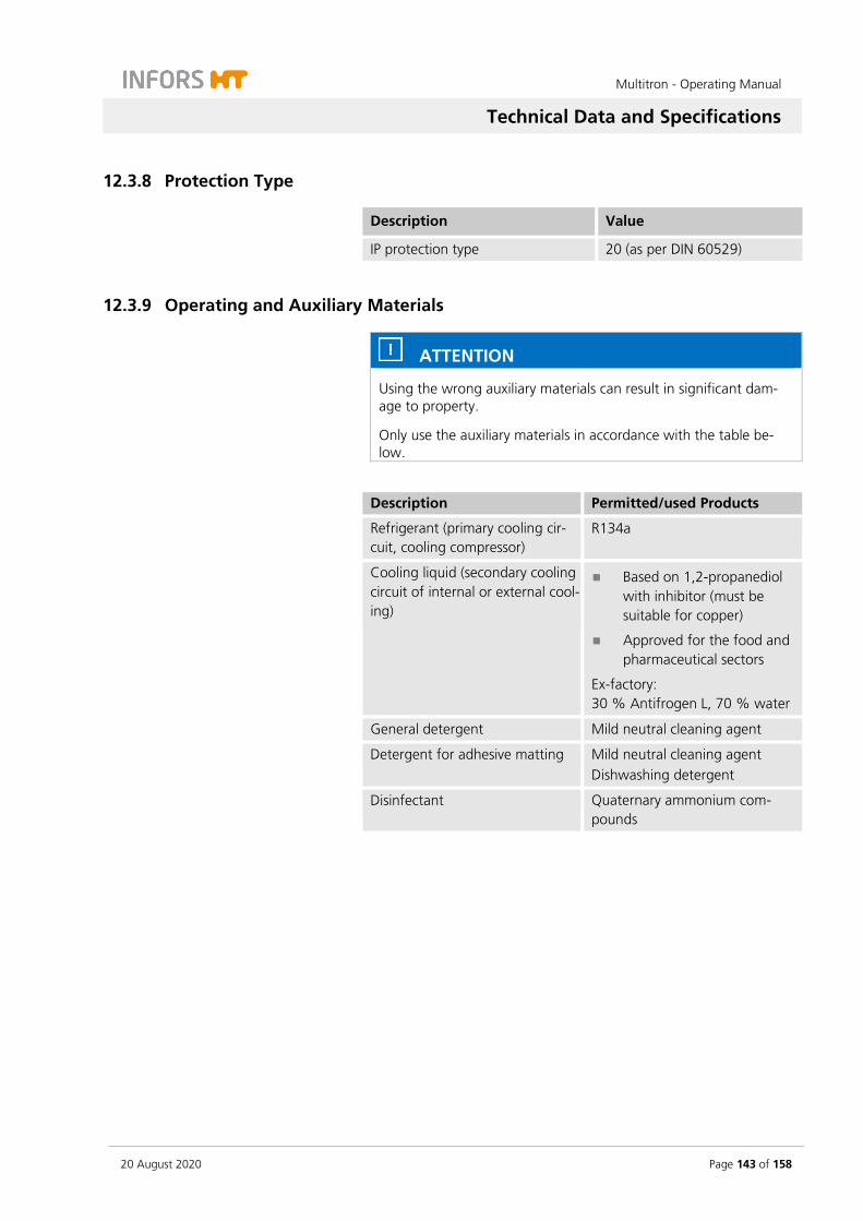
Multitron - Operating Manual
Technical Data and Specifications
20 August 2020 Page 143 of 158
12.3.8 Protection Type
Description Value
IP protection type 20 (as per DIN 60529)
12.3.9 Operating and Auxiliary Materials
ATTENTION
Using the wrong auxiliary materials can result in significant dam-age to property.
Only use the auxiliary materials in accordance with the table be-low.
Description Permitted/used Products
Refrigerant (primary cooling cir-cuit, cooling compressor)
R134a
Cooling liquid (secondary cooling circuit of internal or external cool-ing)
Based on 1,2-propanediol with inhibitor (must be suitable for copper)
Approved for the food and pharmaceutical sectors
Ex-factory: 30 % Antifrogen L, 70 % water
General detergent Mild neutral cleaning agent
Detergent for adhesive matting Mild neutral cleaning agent Dishwashing detergent
Disinfectant Quaternary ammonium com-pounds

Multitron - Operating Manual
Technical Data and Specifications
Page 144 of 158 20 August 2020
12.4 Specifications of Standard Parameters
12.4.1 Rotation Speed Parameter (Shaker Drive)
Description Value Unit
Drive BLDC motor 48 VDC
Sensor Hall sensor
Controller PID controller
Throw (fix throw) 3, 25 or 50 mm
Throw (adjustable throw) 12.5, 19, 25, 50 mm
Increment 1 min-1
Control precision ± 4 min-1
Rotation speeds
INFORMATION
The actual rotation speed that can be achieved depends on differ-ent factors, such as loading, vessel type (e.g. flasks with baffles) or holder (e.g. clamps or Sticky Stuff).
The minimum rotation speed for all device variants is 20 min-1. The maximum rotation speed of a unit depends on the throw and the position of the unit in the stack:
Individual unit 3 mm 25 mm 50 mm
1000 min-1 400 min-1 350 min-1
Two units stacked 3 mm 25 mm 50 mm
Upper unit 1000 min-1 400 min-1 350 min-1
Lower unit 1000 min-1 400 min-1 350 min-1
Three units stacked 3 mm 25 mm 50 mm
Upper unit 1000 min-1 400 min-1 300 min-1
Middle unit 1000 min-1 400 min-1 350 min-1
Lower unit 1000 min-1 400 min-1 350 min-1

Multitron - Operating Manual
Technical Data and Specifications
20 August 2020 Page 145 of 158
Maximum rotation speeds with Sticky Stuff adhesive matting
For a detailed description of the maximum permissible rotation speeds when using the Sticky Stuff adhesive matting, see chapter 5.1.3 "Tray with Sticky Stuff", page 63.
12.4.2 Temperature Parameter (Heating and Ventilation)
Description Value Unit
Power heating 800 W
Setting range 4.0 to 65.0 °C
Increment 0.1 °C
Lowest temperature (above ambient temperature, without op-tional cooling)
10.0
°C
Highest temperature 65.0 °C
Control precision 4 – 50 °C ± 0.3 °C
Control precision > 50 °C ± 0.5 °C
Sensor type Pt100 class 1/3 DIN B
Measurement range of the sensor 0 to 80.0 °C
Ventilation 4 axial fans, 24 VDC
Air circulation 450 m3/h
12.5 Specifications of the Options
The following section summarises all important technical data and specification relating to the options.
12.5.1 Internal Cooling
Cooling unit 900 W
Electrical data
Description Type 230 V Type 115 V Unit
Value
Max. power consumption 1 540 540 W
Max. current consumption 4.2 8.4 A
Fuses (5 x 20 mm, slow-blown) 10 - A
Thermal protection switch - 15 A 1) Power consumption of the compressor

Multitron - Operating Manual
Technical Data and Specifications
Page 146 of 158 20 August 2020
Various
Description Value Unit
Cooling power 2 900 W
Additional mass 3 45 kg
Additional height 290 mm 2) Cooling power at coolant temperature of 20 °C (room temperature of 20 °C) 3) Mass including cooling register and cover
Lowest reachable temperature
Description Value Unit
Single unit 18 °C b. AT 4
Two units stacked 17 °C b. AT
Three units stacked 15 °C b. AT 4) Below ambient temperature
Cooling unit 2 x 900 W
Electrical data
Description Type 230 V Type 115 V Unit
Value
Max. power consumption 1 1080 1080 W
Max. current consumption 8.4 16.8 A
Fuses (5 x 20 mm, slow-blown) 10 - A
Thermal protection switch - 15 A 1) Power consumption of the compressor
Various
Description Value Unit
Cooling power 2 1800 W
Additional mass 3 80 kg
Additional height 290 mm 2) Cooling power at coolant temperature of 20 °C (room temperature of 20 °C) 3) Mass including cooling register and cover

Multitron - Operating Manual
Technical Data and Specifications
20 August 2020 Page 147 of 158
Lowest reachable temperature
Description Value Unit
Single unit 25 °C b. AT 4
Two units stacked 24 °C b. AT
Three units stacked 22 °C b. AT 4) Below ambient temperature
12.5.2 External Cooling
Specifications for the connection
Description Value Unit
Connection (hose Ø) 10 mm
Input pressure max. 4.0 bar
ATTENTION
The installed valve regulates the temperature by closing and open-ing the cycle. Hence it can be necessary to install a bypass from the inlet to the outlet to protect the circulation pump against dam-age.
Requirements for water quality
Water hardness soft or very soft (CaCO3 concentration 0 to 1,5 mmol/l)
For medium hard to very hard water quality alternatively use de-mineralised water.
Requirements for cooling liquid
Based on 1,2-propanediol with inhibitor (must be suitable for copper)
Approved for the food and pharmaceutical sectors
Example: Antifrogen L

Multitron - Operating Manual
Technical Data and Specifications
Page 148 of 158 20 August 2020
12.5.3 Direct Steam Humidification
Casing dimensions
Description Value Unit
Height 340 mm
Depth 80 mm
Width 200 mm
Various
Description Value Unit
Additional mass 3 kg
Water consumption 1 8.3 g/h
Temperature range for use 2 Up to 40 °C
Heating time of the unit 5 min 1) At an ambient temperature of up to 20 °C and at a temperature of 37 °C and
relative humidity of 85 % in the incubation chamber. 2) Temperature in the interior at which functioning can be guaranteed
Target and actual humidity values
Description Value Unit
Setting range 20.0 to 85.0 % rH
Increment 1.0 % rH
Control precision ± 3.0 %r H
Values that can be reached (at 37 °C in the interior and 20 °C room temperature)
85.0 % rH
Electrical data
Description Value Unit
Voltage 230 V
Max. power consumption 125 W
Max. current consumption 0,4 A
Bar heater (in door) 24 V
15 W
Door seal heating 24 V
17 W
Floor heating 24 V
17 W

Multitron - Operating Manual
Technical Data and Specifications
20 August 2020 Page 149 of 158
Specifications for the connection / water quality
Description Value Unit
Connection (hose Ø) 6 to 7 mm
Input pressure 0 to 0.3 bar
Water hardness < 0.01, CaCO3
equivalent mmol/L
Water conductivity min. 5 / max. 20 μS/cm
Dissolved solids < 10 mg/L
ATTENTION
Using tap water can quickly lead to limescale in the vaporiser of the humidification unit, which would affect correct functioning.
Ultra pure water (WFI, water for injection purposes) must not be used either as this is highly corrosive and thus damages the device.
Adding detergents, disinfectants or similar chemicals to the water for the direct steam humidification can damage the device. Only use water without additions, in accordance to the specification.
Specifications for the humidity sensor
Description Value Unit
Sensor type EE071 HCT01-00D
Measurement range 20 to 90 %
Response time < 300 ms
Temperature range for use - 40 to 80 °C
12.5.4 Pressure Elimination Unit for Direct Steam Humidification
Dimensions
Description Value Unit
Depth 185 mm
Height 337 mm
INFORMATION
For detailed information on the external dimensions, refer to the dimension drawings (see chapter 4.3.4 "Dimensions", page 47).

Multitron - Operating Manual
Technical Data and Specifications
Page 150 of 158 20 August 2020
Power supply level sensor
Description Type 230 V Type 115 V Unit
Value
Voltage 230 115 VAC
Frequency 50 60 Hz
Connections
Description Value
Water in Tri-Clamp port DN 8 Inlet pressure: max. 6 bar
12.5.5 CO2 Control
Connection data
Description Value Unit
Connection (hose Ø) 3 to 4 mm
Type of connection Legris
Input pressure 0.5 bar
Various
Description Value Unit
Additional mass 0.5 kg
Vaisala CO2 sensor
Description Value Unit
Sensor type GMP251
Measurement range 0 to 20 % CO2
Accuracy (at 1013 hPa, 25 °C) ± 0.1 % CO2
Target and actual CO2 values
Description Value Unit
Setting range 0 to 20 % CO2
Control range 0.1 to 20 % CO2
Increment 0.1 % CO2
Control precision (at 1013 hPa, 20 °C to 40 °C, up to 20 % CO2)
0.2 % CO2
Gas consump-tion (ventilation opening open)
at 5 % CO2 2 L/h
at 10 % CO2 3.5 L/h
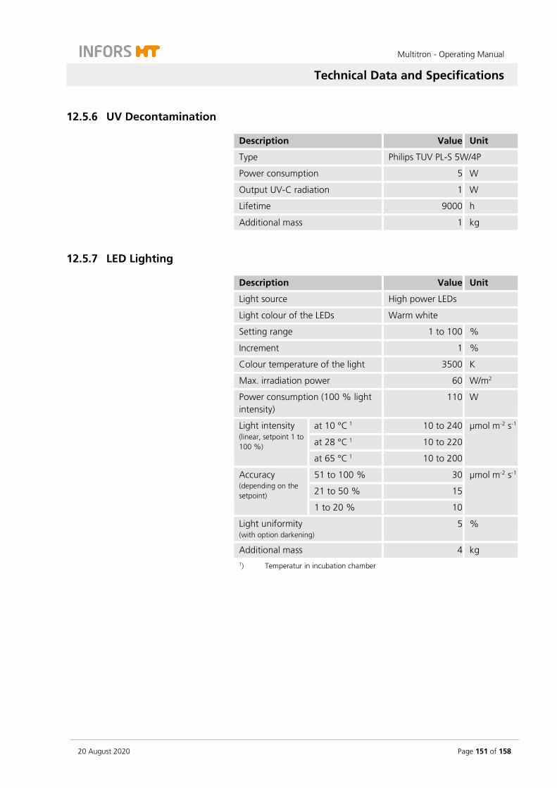
Multitron - Operating Manual
Technical Data and Specifications
20 August 2020 Page 151 of 158
12.5.6 UV Decontamination
Description Value Unit
Type Philips TUV PL-S 5W/4P
Power consumption 5 W
Output UV-C radiation 1 W
Lifetime 9000 h
Additional mass 1 kg
12.5.7 LED Lighting
Description Value Unit
Light source High power LEDs
Light colour of the LEDs Warm white
Setting range 1 to 100 %
Increment 1 %
Colour temperature of the light 3500 K
Max. irradiation power 60 W/m2
Power consumption (100 % light intensity)
110 W
Light intensity (linear, setpoint 1 to 100 %)
at 10 °C 1 10 to 240 µmol m-2 s-1
at 28 °C 1 10 to 220
at 65 °C 1 10 to 200
Accuracy (depending on the setpoint)
51 to 100 % 30 µmol m-2 s-1
21 to 50 % 15
1 to 20 % 10
Light uniformity (with option darkening)
5 %
Additional mass 4 kg 1) Temperatur in incubation chamber


Multitron - Operating Manual
Index
20 August 2020 Page 153 of 158
14 Index
A
Accessories ........................................................ 57
clamps ............................................................ 65
eve® ............................................................... 71
microtitre box ................................................. 68
Sticky Stuff ..................................................... 62
test tube holders ............................................ 67
tray with clamping assembly ........................... 60
tray with pin holders ...................................... 59
tray with sliding bars ...................................... 62
tray with steel clamps ..................................... 59
universal table tray ......................................... 57
Activate/deactivate key pad lock ...................... 115
Activate/deactivate PIN ..................................... 115
Adhesive matting Sticky Stuff ............................. 62
Admin mode .................................................... 113
Air vents ............................................................ 31
ALARM ...................................................... 88, 120
Alarm connection
contacts ......................................................... 29
position .......................................................... 29
specification ................................................. 143
ALARM EXTERN ................................................. 29
Alarm messages ............................................... 120
parameter-specific ........................................ 121
RESTARTED .................................................. 121
ALti .................................................................. 117
Ambient conditions
installation location ........................................ 72
storage ......................................................... 135
Analog output
functional description ..................................... 53
minimum distances ........................................ 74
pin assignment ............................................... 53
Approved cultivation vessels ............................... 11
Auxiliary materials ............................................ 145
B
Base, 13 cm ....................................................... 32
Base, 41 cm ....................................................... 33
bEEP ................................................................. 115
bLoc .......................................................... 92, 121
C
Cable pass-through
position .......................................................... 54
use ................................................................. 55
CE declaration of conformity ................................ 9
Clamps
plastic ............................................................. 66
stainless steel .................................................. 66
Cleaning
base tray ....................................................... 132
Sticky Stuff ..................................................... 64
CO2 control
connect .......................................................... 49
error messages ............................................. 123
fault ............................................................. 128
functional description ..................................... 48
operating ........................................................ 49
specification ................................................. 152
CO2 sensor
position .......................................................... 48
specification ................................................. 152
Commissioning .................................................. 72
Conditions
at the installation location .............................. 72
at the storage location .................................. 135
Connection
CO2 control .................................................... 49
direct steam humidification ............................ 40
Ethernet ......................................................... 30
external alarm ................................................ 29
external cooling .............................................. 37
power supply .................................................. 29

Multitron - Operating Manual
Index
Page 154 of 158 20 August 2020
Coolant ............................................................ 145
Cooling
functional description ..................................... 35
operate .......................................................... 38
refrigerant .................................................... 145
variants .......................................................... 35
Cultivation vessels .............................................. 11
D
Declaration of conformity .................................... 9
Decommissioning ............................................. 119
Demineralized water, pressureless ...................... 40
Detergents ............................................... 131, 145
Device
cleaning ....................................................... 131
disinfecting .................................................. 134
install ............................................................. 72
loading ........................................................... 83
maintenance ................................................ 130
positioning ..................................................... 74
storing .......................................................... 135
switching off ................................................ 119
switching on .................................................. 76
transporting ................................................. 135
Device fuses
position .......................................................... 18
replace ......................................................... 129
type .............................................................. 143
Device settings ................................................. 113
Dimensions ...................................................... 142
Direct steam humidification
connect .......................................................... 40
error messages ............................................. 123
faults ............................................................ 128
function ......................................................... 39
minimum distances ........................................ 74
operate .......................................................... 41
specification ................................................. 150
switch on/off high alarm .............................. 118
water quality ................................................ 150
Discharge outlet
position .......................................................... 30
specification ................................................. 143
Disinfectant ...................................................... 145
Disinfection ...................................................... 134
Display area ........................................................ 86
Distances ............................................................ 74
doAL ................................................................ 117
Door .................................................................. 76
Door alarm
activating/deactivating .................................. 117
function .......................................................... 77
Door heating ...................................................... 39
Door monitoring ................................................ 18
E
Emergency switching off .................................... 33
Emissions ......................................................... 144
Environmental conditions
assembly location ......................................... 144
installation location ........................................ 72
storage ......................................................... 135
Erlenmeyer flasks, requirements ......................... 11
Err .................................................................... 122
ERROR ....................................................... 88, 120
Error messages ................................................. 122
CO2 control ................................................... 123
direct steam humidification .......................... 123
general faults ............................................... 122
shaker drive .................................................. 123
Ethernet interface
configure ...................................................... 117
operation ...................................................... 110
position .......................................................... 30
specification ................................................. 143
eve® ................................................................... 71
Exterior dimensions .......................................... 142
EXTERN .............................................................. 88
External cooling
connect .......................................................... 37
functional description ..................................... 37
specification ................................................. 149
water quality ................................................ 149

Multitron - Operating Manual
Index
20 August 2020 Page 155 of 158
F
Fans ................................................................... 28
Fault notifications ............................................ 122
Faults ......................................................... 88, 120
CO2 control .................................................. 128
direct steam humidification .......................... 128
general faults ....................................... 122, 125
shaker drive .................................................. 126
temperature control ..................................... 127
Fernbach flasks, requirements ............................ 11
Flasks ................................................................. 11
Floor heating ..................................................... 39
Frame
base, 13 cm ................................................... 32
base, 41 cm ................................................... 33
Functional description
analog output ................................................ 53
CO2 control .................................................... 48
cooling ........................................................... 35
direct steam humidification ............................ 39
external cooling .............................................. 37
interior lighting .............................................. 32
pressure elimination unit ................................ 42
temperature control ....................................... 28
Fuses
position .......................................................... 18
replace ......................................................... 129
type .............................................................. 143
G
Guidelines ............................................................ 9
H
Heating ............................................................ 147
Height above sea level ..................................... 117
High ................................................... 92, 120, 121
Holders
fit ................................................................... 80
overview ......................................................... 65
screw sizes ..................................................... 81
Hose pass-through
position .......................................................... 54
use ................................................................. 55
Humidification ................................................... 39
Humidity sensor
position .......................................................... 40
specification ................................................. 151
I
Identification of the device ................................. 34
Identification of the throw ................................. 34
Identification plate
content ............................................................. 9
position .......................................................... 34
Installation ......................................................... 72
Installation location ............................................ 72
Intended use ...................................................... 10
Interior dimensions ........................................... 142
Interior lighting
configure ...................................................... 116
functional description ..................................... 32
specification ................................................. 144
Intermediate base .............................................. 51
Internal cooling
specification ................................................. 147
Interrupted power supply ................................. 119
K
Key tone activate/deactivate ............................. 115
L
LED lighting
operate ........................................................... 52
specification ................................................. 153
Lighting
configure ...................................................... 116
functional description ..................................... 32
specification ................................................. 144
Loading .............................................................. 83
Low ................................................... 92, 120, 121
M
M tray ................................................................ 57
Main switch ....................................................... 33
Mains connection
Multitron - Operating Manual
Index
Page 156 of 158 20 August 2020
overview ......................................................... 29
requirements .................................................. 73
Maintenance .................................................... 130
Maintenance schedule ..................................... 130
Materials .......................................................... 144
Max. rotation speeds ....................................... 146
Maximum rotation speed
with microtitre box ......................................... 69
with Sticky Stuff ............................................. 65
Measurements ................................................. 142
Messages
ALARM ................................................... 88, 120
bLoc ....................................................... 92, 121
Err ................................................................ 122
ERROR .................................................... 88, 120
EXTERN .......................................................... 88
High ....................................................... 92, 120
Low ........................................................ 92, 120
OPn .............................................................. 122
RESTARTED .................................... 88, 119, 121
Setpoint ......................................................... 92
Microtitre box
fit ................................................................... 80
overview ......................................................... 68
Minimum distances ............................................ 74
Misuse ............................................................... 10
Motor, specification ......................................... 146
Moving .............................................................. 72
O
Opening the door .............................................. 76
Operating conditions ................................. 72, 144
Operating panel ................................................. 33
Operation
CO2 control .................................................... 49
cooling ........................................................... 38
direct steam humidification ............................ 41
LED lighting .................................................... 52
set parameter setpoint ................................... 93
switching off ................................................ 119
switching on device ........................................ 76
turning parameter off ..................................... 94
turning parameter on ..................................... 94
UV decontamination ....................................... 50
OPn .................................................................. 122
Option function ............................................... 113
Options
analog output ................................................ 53
CO2 control .................................................... 48
cooling ........................................................... 35
darkening ....................................................... 53
direct steam humidification ............................ 39
LED lighting .................................................... 52
pressure elimination unit ................................ 42
removable shelf .............................................. 51
UV decontamination ....................................... 50
Overheating shut-down ..................................... 18
Overview
accessories ...................................................... 57
components ................................................... 21
parameters ..................................................... 91
timer function ................................................ 96
P
Parameter
set setpoint ..................................................... 93
turning off ...................................................... 94
turning on ...................................................... 94
Parameters
carbon dioxide concentration (CO2) ................ 91
light (Light) ..................................................... 91
relative humidity (Humid) ................................ 92
rotation speed (RPM) ...................................... 92
temperature (Temp) ........................................ 91
Permitted cultivation vessels ............................... 11
Placing the device under a table ......................... 75
POWER .............................................................. 33
Power supply
mains connection ........................................... 29
requirements .................................................. 73
Power switch ...................................................... 33
Pre-fitted trays ................................................... 58
Pressure elimination unit .................................... 42

Multitron - Operating Manual
Index
20 August 2020 Page 157 of 158
autoclaving .................................................... 45
cleaning ......................................................... 43
dimensions ..................................................... 47
specification ................................................. 151
Programming cyclic change .............................. 105
Programming single change ............................. 100
Protection classes ............................................... 10
Protection type ................................................ 145
Pt100
position .......................................................... 28
specification ................................................. 147
Purpose ............................................................ 10
Q
Quickload spacer ............................................... 60
R
Radial fans ......................................................... 28
Rating plate
position .......................................................... 34
Refrigerant ....................................................... 145
Removable shelf ................................................. 51
RESTARTED ........................................ 88, 119, 121
Ring spacer ........................................................ 60
Risk category ..................................................... 10
Room temperature ........................................... 144
Rotation speed
set upper threshold value ............................. 113
specification ................................................. 146
with microtitre box ......................................... 69
with Sticky Stuff ............................................. 65
S
Safety features ................................................... 18
Screw sizes
holders ........................................................... 81
table ............................................................. 132
Sensor
CO2 ................................................................ 48
humidity ......................................................... 40
Pt100 ............................................................. 28
Servicing .......................................................... 130
Set table brake force ........................................ 114
Setpoint ...................................................... 92, 93
Settings menu .................................................. 113
Setup ............................................................... 113
Shaker drive
error messages ............................................. 123
fault ............................................................. 126
specification ................................................. 146
Signs
alarms and errors ............................................ 88
Sound pressure ................................................ 144
Specification
basic unit ...................................................... 142
CO2 control ................................................... 152
CO2 sensor .................................................... 152
cooling ......................................................... 147
cultivation vessels ........................................... 11
direct steam humidification .......................... 150
external cooling ............................................ 149
heating ......................................................... 147
humidity sensor ............................................ 151
LED lighting .................................................. 153
pressure elimination unit .............................. 151
shaker drive .................................................. 146
UV decontamination ..................................... 153
ventilation .................................................... 147
Start-up .............................................................. 72
Sterilisation ........................................................ 50
Sticky Stuff
maximum rotation speed ................................ 65
overview ......................................................... 62
Storage ............................................................ 135
Structure ............................................................ 21
Switching off .................................................... 119
Switching on ...................................................... 76
T
Table
installing ....................................................... 132
overview ......................................................... 26
screw sizes .................................................... 132

Multitron - Operating Manual
Index
Page 158 of 158 20 August 2020
set brake force ............................................. 114
stopping automatically ................................... 76
uninstalling .................................................. 132
Temperature control
fault ............................................................. 127
functional description ..................................... 28
set lower threshold value .............................. 114
set upper threshold value ............................. 114
specification ................................................. 147
Test tube holder
fit ................................................................... 80
overview ......................................................... 67
Thermal protection switches .............................. 18
Threshold value
rotation speed .............................................. 113
temperature ................................................. 114
Throw ........................................................ 34, 146
identification .................................................. 34
Timer function
activate/deactivate ........................................ 116
cyclic change ................................................ 105
cyclical change ............................................... 98
interrupted power supply ............................. 119
one-time change ............................................ 97
single change ............................................... 100
stopping ....................................................... 108
Transport ......................................................... 135
Tray
fit holders ....................................................... 80
loading ........................................................... 83
pre-fitted ........................................................ 58
remove ........................................................... 77
universal ......................................................... 57
with clamping assembly .................................. 60
with pin holders ............................................. 59
with sliding bars ............................................. 62
with steel clamps ............................................ 59
with Sticky Stuff ............................................. 62
Tray lock ............................................................ 77
U
Universal table tray ............................................. 57
UV decontamination
operation ........................................................ 50
setup .............................................................. 50
specification ................................................. 153
V
Ventilation ....................................................... 147
Ventilation opening ............................................ 31
W
Water
inlet ................................................................ 37
outlet ............................................................. 37
Water quality
direct steam humidification .......................... 150
external cooling ............................................ 149
Weights ........................................................... 142

Digitize your bioprocesses
The platform software for your bioprocesses
eve® – the Bioprocess Platform Software Able to do more than just plan, control and analyze your bioprocesses, eve® software
integrates workflows, devices, bioprocess information and big data in a platform that lets you organize your projects in the cloud, no matter how complex they are.
Learn more at www.infors-ht.com/eve