MULTIQUIP Model GA-9.7 HZ A.C. GENERATOR
70
© COPYRIGHT 2001, MULTIQUIP INC. MULTIQUIP PARTS AND OPERATION MANUAL Model GA-9.7 HZ A.C. GENERATOR MULTIQUIP INC. PARTS DEPARTMENT: 18910 WILMINGTON AVE. 800-427-1244 CARSON, CALIFORNIA 90746 FAX: 800-672-7877 310-537-3700 SERVICE DEPARTMENT/TECHNICAL ASSISTANCE: 800-421-1244 800-478-1244 FAX: 310-537-3927 FAX: 310-631-5032 E-mail:[email protected] • www:multiquip.com Atlanta • Boise • Dallas • Houston • Newark Montreal, Canada • Manchester, UK Rio De Janiero, Brazil • Guadalajara, Mexico Revision #2 (03/05/01)
Transcript of MULTIQUIP Model GA-9.7 HZ A.C. GENERATOR

© C
OP
YR
IGH
T 2
001,
MU
LTIQ
UIP
IN
C.
MULTIQUIP
PARTS AND OPERATION MANUAL
Model GA-9.7 HZA.C. GENERATOR
MULTIQUIP INC..... PARTS DEPARTMENT:18910 WILMINGTON AVE. 800-427-1244CARSON, CALIFORNIA 90746 FAX: 800-672-7877310-537-3700 SERVICE DEPARTMENT/TECHNICAL ASSISTANCE:800-421-1244 800-478-1244FAX: 310-537-3927 FAX: 310-631-5032E-mail:[email protected] • www:multiquip.comAtlanta • Boise • Dallas • Houston • NewarkMontreal, Canada • Manchester, UKRio De Janiero, Brazil • Guadalajara, Mexico
Revision #2 (03/05/01)

PAGE 2 — GA-9.7 HZ A.C. GENERATOR— PARTS & OPERATION MANUAL — REV. #2 (03/05/01)

GA-9.7 HZ A.C. GENERATOR — PARTS & OPERATION MANUAL — REV. #2 (03/05/01) — PAGE 3
HERE'S HOW TO GET HELPPLEASE HAVE THE MODEL AND SERIAL NUMBERON-HAND WHEN CALLING
PARTS DEPARTMENT800-427-1244 or 310-537-3700FAX: 800-672-7877 or 310-637-3284
SERVICE DEPARTMENT/TECHNICAL ASSISTANCE800-478-1244 or 310-537-3700FAX: 310- 537-4259
WARRANTY DEPARTMENT888-661-4279, or 310-661-4279FAX: 310- 537-1173
MAIN800-421-1244 or 310-537-3700FAX: 310-537-3927

PAGE 4 — GA-9.7 HZ A.C. GENERATOR— PARTS & OPERATION MANUAL — REV. #2 (03/05/01)
TABLE OF CONTENTS
Here's How To Get Help ............................................ 3Table Of Contents ..................................................... 4Parts Ordering Procedures ....................................... 5Rules For Safe Operation ......................................... 6Operation and Safety Decals .................................... 7Specifications ............................................................ 8General Information .................................................. 9
Multiquip GA-9.7 HZ —AC Generator
Controls and Indicators ........................................... 10Installation ............................................................... 11Pre-Setup ........................................................... 12-13Instrumentation ....................................................... 14Load Application ..................................................... 15Operating Instructions............................................. 16Maintenance ........................................................... 17Preparation For Long Term Storage ....................... 18Wiring Diagram ....................................................... 19Troubleshooting (Engine) ................................... 20-21Troubleshooting (Generator) ............................. 22-23Explanation Of Codes In Remarks Column ............ 24Suggested Spare Parts ........................................... 25Generator Assembly .......................................... 26-27Control Box Assembly ........................................ 28-29Pipe Frame Assembly ........................................ 30-31Nameplate And Decals ...................................... 32-33
NOTE
Specification and part numberare subject to change withoutnotice.
Honda GX610 K1 EngineCylinder Head Assembly ....................................34-35Cylinder Barrel Assembly ...................................36-37Crankcase Cover Assembly ...............................38-39Crankshaft Assembly .........................................40-41Piston Assembly .................................................42-43Camshaft Assembly ...........................................44-45Recoil Starter Assembly.....................................46-47Fan Cover Assembly ..........................................48-49Carburetor Assembly .........................................50-51Air Cleaner Assembly .........................................52-53Muffler Assembly ...............................................54-55Fuel Pump Assembly .........................................56-57Flywheel Assembly ............................................58-59Ignition Coil Assembly ........................................60-61Starter Motor Assembly .....................................62-63Governor Control Assembly ...............................64-65Labels ................................................................66-67Gasket Kit ................................................................ 68
Terms and Conditions Of Sale — Parts .................. 69

GA-9.7 HZ A.C. GENERATOR — PARTS & OPERATION MANUAL — REV. #2 (03/05/01) — PAGE 5
PARTS ORDERING PROCEDURES
Get special freight allowanceswhen you order 10 or moreline items via FAX!**n UPS Ground Service at no charge for freight
n PS Third Day Service at one-half of actual freight cost
No other allowances on freight shipped by any other carrier.
**Common nuts, bolts and washers (all items under $1.00 list price)do not count towards the 10+ line items.
*DISCOUNTS ARE SUBJECT TO CHANGE*
Fax order discount and UPS special programs revised June 1, 1995
Earn Extra Discounts whenyou order by FAX!
All parts orders which include complete part numbersand are received by fax qualify for the following extradiscounts:
Number ofline items ordered Additional Discount1-9 items 3%
10+ items** 5%
Now! Direct TOLL-FREE accessto our Parts Department!
Toll-free nationwide: 800-421-1244Toll-free FAX:
800/6-PARTS-7 • 800-672-7877
n Dealer account numbern Dealer name and addressn Shipping address (if different than billing address)n Return fax numbern Applicable model numbern Quantity, part number and description of each partn Specify preferred method of shipment:
• UPS Ground
• UPS Second Day or Third Day*
• UPS Next Day*
• Federal Express Priority One (please provide us with your FederalExpress account number)*
• Airborne Express*
• Truck or parcel post
*Normally shipped the same day the order is received, if prior to 2PM west coast time.
Extra Fax Discount
Extra Fax Discount
Extra Fax Discount
Extra Fax Discount
Extra Fax Discount
for Domestic USAfor Domestic USAfor Domestic USAfor Domestic USA
for Domestic USA
Dealers OnlyDealers OnlyDealers OnlyDealers OnlyDealers Only

PAGE 6 — GA-9.7 HZ A.C. GENERATOR— PARTS & OPERATION MANUAL — REV. #2 (03/05/01)
RULES FOR SAFE OPERATION
CAUTION:Failure to follow instructions in this manualmay lead to serious injury or even death! Thisequipment is to be operated by trained andqualified personnel only! This equipment isfor industrial use only.
The following safety guidelines should always be used whenoperating the GA-9.7 HZ Generator:
GENERAL SAFETY
� DO NOT operate or service this equipment before readingthis entire manual.
� This equipment should not be operated by persons under 18years of age.
� NEVER operate this equipment without proper protectiveclothing, shatterproof glasses, steel-toed boots and otherprotective devices required by the job.
� This generator is a source of potentially LETHAL high voltage.Never permit unqualified personnel-especially children tooperate the generator.
� Always refuel in a well-ventilated area, away from sparks andopen flames.
� Always use extreme caution when working with flammableliquids. When refueling, stop the engine and allow it to cool.DO NOT smoke around or near the machine. Fire or explosioncould result from fuel vapors, or if fuel is spilled on a hotengine.
� This generator is equipped with a ground terminal for yourprotection. Always complete the grounding path from thegenerator to an external grounding source.
� NEVER operate this generator, or handle any electricalequipment while standing in water, while bare foot, whilehands are wet, or in the rain. Electrical shock could occurcausing severe bodily harm or even death.
� Keep electrical cords in good condition. Worn, bare or frayedwiring can cause electrical shock, leading to bodily harm oreven death.
� This generator requires an adequate free flow of cooling air.Never operate the generator in any enclosed or narrow areawhere free flow of the air is restricted. If the air flow is restrictedit will cause serious damage to the generator and may causeinjury to people.
� NEVER touch the hot exhaust manifold, muffler or cylinder.Allow these parts to cool before servicing generator.
� Provide adequate ventilation when operating the generator.DO NOT operate the generator in any enclosed or narrowspace. The generator's gasoline engine gives off DEADLYcarbon monoxide gas.
� NEVER operate the generator in an explosive atmosphere ornear combustible materials. An explosion or fire could resultcausing severe bodily harm or even death.
� Always make sure that the generator is secure on level groundso that it cannot slide or shift around, endangering workers.Also keep the immediate area free of bystanders.
� When using a concrete vibrator or a similar device that isimmersed in a water based solution, make sure the device isequipped with short circuit protection.
� Always use rubber boots and gloves when operating aconcrete vibrator or similar device.
� Use adequate size connecting cable for extension.
� Maintain electrical cords in good condition and frequentlyreplace the entire cable of the concrete vibrator with a newone.
� High Temperatures – Allow the machine and engine to coolbefore adding fuel or performing service and maintenancefunctions. Contact with hot components can cause seriousburns.
Emergencies
� Always know the location of the nearest fire extinguisherand first aid kit. Know the location of the nearest telephone.Also know the phone numbers of the nearest ambulance,doctor and fire department. This information will beinvaluable in the case of an emergency.
Maintenance Safety� NEVER lubricate components or attempt service on a running
machine.
� Always allow the machine a proper amount of time to coolbefore servicing.
� Keep the machinery in proper running condition.
� Fix damage to the machine immediately and always replacebroken parts.
� Dispose of hazardous waste properly. Examples of potentiallyhazardous waste are used motor oil, fuel and fuel filters.
� DO NOT use food or plastic containers to dispose ofhazardous waste.
� DO NOT pour waste, oil or fuel directly onto the ground,down a drain or into any water source

GA-9.7 HZ A.C. GENERATOR — PARTS & OPERATION MANUAL — REV. #2 (03/05/01) — PAGE 7
OPERATION AND SAFETY DECALS
Machine Safety Decals
The GA-9.7 HZ portable generator is equipped with a number of safety decals. These decals are provided for operator safety andmaintenance information. The illustration below shows these decals as they appear on the machine. Should any of these decalsbecome unreadable, replacements can be obtained from your dealer.

PAGE 8 — GA-9.7 HZ A.C. GENERATOR— PARTS & OPERATION MANUAL — REV. #2 (03/05/01)
GA-9.7 HZ — SPECIFICATIONS
Effects of Altitude and HeatThe maximum output of the engine listed above is applicable to supplying electrical power for continuous service at ambientconditions in accordance with SAE Test cord J607. The above ambient conditions are at standard sea level, with a barometricreading of 29.92 inches and a temperature of 60 degrees fahrenheit.
Generally, the engine output power will decrease 3 1/2% for each 1000 feet of altitude above sea level, and 1% for each 10� Ffahrenheit above the standard temperature of 60� F
snoitacificepS.1elbaTLEDOM ZH7.9-AG
epyT dleiFgnivloveRepyTsselhsurB,elop-2
rotareneGelcyC06
tuptuO.xaM sttaW0079
)suounitnoc(tuptuOdetaR sttaW0048
egatloVdetaR V042/021
tnerruCdetaR A0.03/0.02
esahP )eriw-3(esahPelgniS
ycneuqerF zH06
deepSdetaR MPR0063
rotcaFrewoP %001
)rekaerBniaM(tnerruCxaM spmA53elop-2
enignE
ledoM DV1K016XGadnoH
epyTniwT-V09HVOekorts4delooc-riA
enigneenilosagtfahslatnoziroh
ekortSXeroB ni06.2Xni30.3
tnemecalpsiD cc8.81
tuptuOdetaR .M.P.R0063/.P.H0.81
yticapaCknaTleuF snollaG.S.U01.xorppA
leuF enilosaGelibomotuAdedaelnU
yticapaCliOebuL stnip61/13
dohteMlortnoCdeepS epyTthgiew-ylFlagufirtneC
dohteMgnitratS tratSlioceR/cirtcelE
)HXWXL(noisnemiD mm007X045X008
thgieWteNyrD ).gK651(sbl443

GA-9.7 HZ A.C. GENERATOR — PARTS & OPERATION MANUAL — REV. #2 (03/05/01) — PAGE 9
GA-9.7 HZ — GENERAL INFORMATION
GA-9.7 HZ FAMILIARIZATIONGeneratorThe Multiquip Model GA-9.7 HZ generator has been designedas a portable lightweight power source for 60 Hz (single-phase) vibrators, lighting facilities, power tools, submersiblepumps and other industrial and construction machinery.This generator is powered by a HONDA gasoline engine.The alternator, a brushless revolving-field type, ispermanently aligned to the engine through rigid coupling.The generator is mounted on rubber vibration isolators thathave a steel base backplate which is attached to theprotective steel pipe carrying frame. The protective carryingframe is made of steel tubing and fully wraps around thegenerator to protect against damage.This portable generator is supplied with a electrical controlbox. To reduce vibration caused by the engine, the controlbox is also placed on rubber isolators.
Control BoxThe control box is provided with the following:
� Three 120/240V output receptacles (single phase).
� Two 120 V output GFI receptacles (single phase).,
� Five circuit breakers, one for each receptacle.
� One 240 V, 60 Hz main circuit breaker.
� AC Voltmeter.
� Idle Control Switch.
� Full Power Switch.
� Operation Switch.
Excitation SystemAll GA-series generators use a magnet attached to a flywheelto produce AC voltage from a lamp coil beneath the flywheel.As the magnet passes the coil it produces approximately19-22 AC volts.This voltage (19-22 VAC) is then sent to the control box thatcontains three rectifying diodes:
� Excitation (diode 1)� Battery (diode 2)� Slow Down (diode 3)
The AC voltage will pass through the excitation diode thatconverts the voltage to DC power.
This DC power is then sent to the excitation windings housedwithin the main windings commonly called the "stator".This voltage is then transferred into the rotor throughinduction. The rotor contains two diodes within it which rectifythe DC voltage and send it out through the main windings,as AC voltage.
EngineThe four-cycle air-cooled HONDA gasoline engine is designedto meet every performance requirement of this generator.Reference Table 1, page 8 for engine specifications.Figure 1 (page 10) shows the basic controls and indicatorsfor the GA-9.7 HZ generator.
WARNING:Before connecting this generator toany building’s electrical system, alicensed electrician must install anisolation (transfer) switch.
Serious injury or death may resultwithout this transfer switch.
NOTE
In keeping with Multiquip's policy ofconstantly improving its products, thespecifications quoted herein are subjectto change without prior notice.

PAGE 10 — GA-9.7 HZ A.C. GENERATOR— PARTS & OPERATION MANUAL — REV. #2 (03/05/01)
GA-9.7 HZ — CONTROLS AND INDICATORS
Figure 1. Controls and Indicators

GA-9.7 HZ A.C. GENERATOR — PARTS & OPERATION MANUAL — REV. #2 (03/05/01) — PAGE 11
GA-9.7 HZ — INSTALLATION
Outdoor Installation
Install the generator in a location where it will not be exposed torain or sunshine. Make sure that the generator is on secure levelground so that it cannot slide or shift around. Also install thegenerator in a manner so that the exhaust will not be dischargedin the direction of nearby homes.
The installation site must be relatively free from moisture anddust. All electrical equipment should be protected from excessivemoisture. Failure to do will result in deterioration of the insulationand will result in short circuits and grounding.
Foreign materials such as dust, sand, lint and abrasive materialshave a tendency to cause excessive wear, not only to the engineparts, but also to the alternator parts.
CAUTION :
Pay close attention to ventilation whenoperating the generator inside confinedareas. The engine exhaust containsnoxious elements.
Indoor Installation
Exhaust gases from gasoline engines are extremelypoisonous. Whenever an engine is installed indoors theexhaust fumes must be vented to the outside. The engineshould be installed at least two feet from any outside wall.Using an exhaust pipe which is too long or too small cancause excessive back pressure which will cause the engineto heat excessively and possibly burn the valves.
Eliminate the danger of deadly carbon monoxide gas.Remember that exhaust fumes from any gasoline engineare very poisonous if discharged in a closed room, butharmless if allowed to mix with the outside air. If the generatoris installed indoors, you must make provisions for ventingthe engine exhaust to the outside of the building.
CAUTION :Preventing electrical shock. Pay closeattention to handling when operatingconcrete vibrators. Always use rubberboots and gloves to insulate the body froma short circuit.

PAGE 12 — GA-9.7 HZ A.C. GENERATOR— PARTS & OPERATION MANUAL — REV. #2 (03/05/01)
General Inspection Prior to Operation
This generator has been thoroughly inspected prior toshipment from the factory. However, be sure to check fordamaged parts or components, or loose nuts and bolts, whichcould have occurred in transit.
Ground
The nut and ground terminal on the generator should alwaysbe used to connect the generator to a suitable ground. Theground path should be of #8 size wire.
Connect the terminal of the ground wire between the lockwasher and the nut and tighten the nut fully. Connect theirend of the wire to a suitable ground.
Ground the Generator
Ground the generator from its ground connector so thatresistance to ground is 500 ohms or less.
Ground the Tool
Ground the tool (load) in the same manner as the generator.
Circuit Breaker
To protect the generator from an overload, circuit breakers areprovided for single (60 Hz) phase on the control box. Makesure to switch the circuit breakers to the "OFF" positionprior to starting the engine.
Extension Cable
When electric power is to be provided to various tools or loads atsome distance from the generator, extension cords are normallyused. Cables should be sized to allow for distance in length andamperage so that the voltage drop between the generator andpoint of use (load) is held to a minimum. Use the cable selectionchart (Table 2 ) as a guide for selecting proper cable size.
GA-9.7 HZ — PRE-SETUP
)noitarepoesahpelgnis,zH06(noitceleSelbaC.2elbaT
tnerruCni
serepmA
sttaWnIdaoL htgneLelbaCelbawollAmumixaM
021tAstloV
042tAstloV
eriW01# eriW21# eriW41# eriW61#
5.2 003 006 .tf0001 .tf006 .tf573 .tf052
5 006 0021 .tf005 .tf003 .tf002 .tf521
5.7 009 0081 .tf053 .tf002 .tf521 .tf001
01 0021 0042 .tf052 .tf051 .tf001
51 0081 0063 .tf051 .tf001 .tf56
02 0042 0084 .tf521 .tf57 .tf05
03 0063 0027 .tf57 .tf05 .tf53
.egatlovwolmorftlusernacegamadtnempiuqE:NOITUAC

GA-9.7 HZ A.C. GENERATOR — PARTS & OPERATION MANUAL — REV. #2 (03/05/01) — PAGE 13
Lubrication Oil
Fill the engine crankcase with lubricating oil through the fillerhole, but do not overfill. Make sure the generator is level.With the dipstick inserted all the way, but without beingscrewed into the filler hole, verify that the oil level ismaintained between the two notches on the dipstick.
The oil listed in Table 3 is recommended to ensure betterengine performance. Use class SC or higher grade motoroil.
Fuel
Fill the fuel tank with clean and fresh unleaded gasoline. Donot fill the tank beyond capacity.
Pay attention to the fuel tank capacity when replenishingfuel. Refer to the fuel tank capacity listed on page 8Specification Table1.
The fuel tank cap must be closed tightly after filling.
Handle fuel in a safety container. If the container does not havea spout, use a funnel.
CAUTION :Never fill the fuel tank while the engine isrunning or in the dark. Gasoline spillageon a hot engine can cause a fire orexplosion. If gasoline spillage occurs, wipeup the spilled gasoline completely toprevent fire hazards.
GA-9.7 HZ — PRE-SETUP
liOrotoMdednemmoceR.3elbaT
erutarepmeTegnaR
liOepyT
F°32~F°401)C°5-~C°04(
03EAS
F°5~F°32)C°51-~C°5-(
03-W01easro02EAS
woleB )°51-(C°5 03-W01EASroW01EAS
NOTE
This HONDA engine is equipped with a low oilshutdown capability. A built in sensor willautomatically turn off the engine should the oil levelfall below a safe operating condition. Make surethe generator is placed on level ground. Placingthe generator on level ground will ensure that thelow oil sensor will function properly.
PAGE 14 — GA-9.7 HZ A.C. GENERATOR— PARTS & OPERATION MANUAL — REV. #2 (03/05/01)
GA-9.7 HZ — INSTRUMENTATION
Power Outlets
The generator has the following 60 Hz 120/240 volt single-phase receptacles.
� Single Phase
Two Duplex NEMA (GFCI) 5-20R (120V, 20 Amp)
One Twist Lock NEMA L5-30R (120V, 30 Amp)
One Twist Lock NEMA L6-20R (240V, 20 Amp)
One Twist Lock NEMA L5-30R (120/240, 30 Amp)
Main Circuit Breaker (2-Pole 60 Hz)
This 2-pole 35 amp breaker protects the generator from shortcircuiting or overloading from the 60 Hz single phase load.
CAUTION :When using a combination of dualreceptacles, total load should not exceedthe rated capacity of the generating.
Idle Control Switch
This unit is provided with an automatic idle control for noisesuppression and reduced fuel consumption. The automaticidle control automatically engages under a no-load condition.With the automatic idle control switched “ON”, the enginerevolutions will automatically drop to about 2500 rpm (low-speed operation) within 3 seconds after the load stops. Whenthe operation is resumed, the engine speed is automaticallyincreased to about 3600 rpm (high-speed operation) as soonas the load is connected.
Fuel Gauge
The fuel gauge is located on the fuel tank and allows easymonitoring of the fuel level.
AC Voltmeter
This voltmeter indicates (with a mark) the rated 60 Hz,single phase output voltage. In addition the voltmeter canalso be used as a diagnostic tool.
If the voltmeter indicator (needle) is below the rated voltage,engine problems may exist (low/high RPM's). To preventdamage to the generator or power tools turn the generatorOFF and consult your authorized Multiquip service dealer.

GA-9.7 HZ A.C. GENERATOR — PARTS & OPERATION MANUAL — REV. #2 (03/05/01) — PAGE 15
GA-9.7 HZ — LOAD APPLICATION
Single Phase Load
Always be sure to check the nameplate on the generatorand equipment to insure the wattage, amperage andfrequency requirements are satisfactorily supplied by thegenerator for operating the equipment.
Generally, the wattage listed on the nameplate of theequipment is its rated output. Equipment may require 130—150% more wattage than the rating on the nameplate, asthe wattage is influenced by the efficiency, power factor andstarting system of the equipment.
NOTEIf wattage is not given on the equipment'sname plate, approximate wattage may bedetermined by multiplying nameplatevoltage by the nameplate amperage.
WATTS = VOLTAGE x AMPERAGE
To determine the running wattage for your load, multiply therunning wattage as indicated by steps 1, 2, and 3 below:
1. INCANDESCENT LOADSLights, heaters and similar appliances.Total the running wattage and multiply by 1.Example:29 light bulbs @ 100W each = 2.9 KWuse a 3 KW generator.
2. SMALL MOTORSDrills and other small power tools.Total the running wattage and multiply by 2.Example:A 1 inch drill runs at 1 KWuse a 2 KW generator.
3. LARGE MOTORSSubmersible pumps, table saws etc.Total the running wattage and multiply by 3.Example:A conveyor belt runs at 8 KWuse a 24 KW generator.
CAUTION:Motors and motor-driven equipment drawmuch greater current for starting thanduring operation.
An inadequate size connecting cable which cannot carrythe required load can cause a voltage drop which can burnout the appliance or tool and overheat the cable.
The idle control is operated at minimum load capacity of100W. If the load capacity is less than 100W, throw the idlecontrol switch to the OFF position.

PAGE 16 — GA-9.7 HZ A.C. GENERATOR— PARTS & OPERATION MANUAL — REV. #2 (03/05/01)
GA-9.7 HZ — OPERATING INSTRUCTIONS
Before Starting
1. Be sure to disconnect the electrical load and switch themain circuit breaker to the “OFF” position prior to startingthe engine.
2. Never start the engine with the main circuit breaker “ON”.
3. Check the lubricating oil level prior to starting the engine.Make sure the generator is level. The oil level must bemaintained between two notches on the dipstick.
4. When there is not enough lubricating oil, fill the crankcasewith high grade motor oil. Use a high quality detergentoil classified SC, SD or SE. (See Table 3 on page 13)
CAUTION:CAUTION:CAUTION:CAUTION:CAUTION:
Starting
1. Place the idle control switch in the “ON” (up) position.
2. Close the choke. Adjust the opening of the choke valveaccording to operating conditions. When the engine iswarm or the air temperature is high, close the chokevalve halfway or open it all the way.
3. Confirm that the main circuit breaker on the generatorcontrol box is “OFF”.
4. Set the operation switch to the “ON” position and graspthe starting rope and slowly pull it out. The resistancebecomes hardest at a certain position, correspondingto the compression point. Rewind the rope a little fromthat point and pull out sharply.
5. If the engine fails to start, repeat the procedure.
Warm up
1. When the engine starts, open the choke slowly.
2. Run the engine at low speed for 3 minutes without loaduntil the engine warms up.
3. Turn the idle control switch to the "OFF" (down) positionand check the voltage by referring to the voltmeter onthe control box.
CAUTION:CAUTION:CAUTION:CAUTION:CAUTION:
1. Check the generator for abnormal noise and smells. Thenconnect the load to the receptacles of the generator.
2. Switch the main circuit breaker to the “ON” position andturn the idle control switch to the “ON” (down) positionfor normal (load) engine operation.
Operation
Check the voltage by referring to the voltmeter on the controlbox. When the voltmeter indicates 120 volts, 120 volts fromthe 120V receptacles and 240 volts from the 240V receptaclecan be obtained at the same time. Refer to Figure 1, Controlsand Indicators, item 4 on page 10.
Stopping the Engine
CAUTION:CAUTION:CAUTION:CAUTION:CAUTION:
1. Remove the load from the generator. Place the circuitbreaker in the “OFF” position. Refer to Figure 1, item 5on page 10. Run the engine (no-load) with the idle controlswitch set to the ON position for three to five minutes,then stop the engine.
2. Turn the START/STOP switch to the “STOP” position.
3. Never stop the engine suddenly while running at highspeed.
� DO NOT pull the starter rope all the wayto the end.
� DO NOT release the starter rope afterpulling. Allow it to rewind as soon aspossible.
DO NOT change the engine speed controllever which has been set at the factory priorto shipping.
NEVER stop the engine suddenly whilerunning at high speeds.
� NEVER start the engine when the oil levelis below the lower mark on the dipstick.
� Check the fuel level on the fuel gauge.When fuel is low, fill the fuel tank withclean fresh unleaded automotive gasoline.
� If gasoline spillage occurs, completelywipe up the spilled gasoline.
CAUTION:CAUTION:CAUTION:CAUTION:CAUTION:

GA-9.7 HZ A.C. GENERATOR — PARTS & OPERATION MANUAL — REV. #2 (03/05/01) — PAGE 17
General Inspection
At least daily or prior to each use, the generating set shouldbe cleaned and inspected for deficiencies. Check for loose,missing or damaged nuts, bolts or other fasteners. Also checkfor fuel or oil leaks.
Engine Side (Refer to the Engine Instruction Manual)
Check Oil Level
Check the crankcase oil level prior to each use, or when thefuel tank is filled. Make sure the generating set is level. Theoil level must be between the two notches on the dipstick.
Changing Oil
Change oil after the first 20 hours of operation. Drain andrefill the engine crankcase every 50 operating hours or oncea week thereafter. Drain crankcase oil into a suitable containerwhile engine is still warm. Replace the drain plug tightly. Addoil through the filler hole.
Air Cleaner
Every 50 hours: Remove air cleaner element (std. or heavyduty types), and wash in kerosene or liquid detergent andhot water. Wrap foam element in a cloth and squeeze dry.Wipe heavy duty paper element dry with toweling. Saturateelement with kerosene; squeeze excess from foam element.Wipe excess from heavy duty paper element.
GA-9.7 HZ — MAINTENANCE
Service Daily
If engine is operating in very dusty and dry grass conditions.A clogged air cleaner will result in high fuel consumption,loss of power and excessive carbon buildup in thecombustion chamber.
Cleaning the Fuel Strainer
Clean the fuel strainer if it contains dust or water. Removedust or water in the strainer cap and wash it in gasoline.Securely fasten the fuel strainer cap so that fuel will notleak. Check the fuel strainer every 200 hours of operation oronce a month.
Spark Plug
Remove carbon build-up on the spark plug (Figure 5) with awire brush. Set the spark plug gap to 0.6—0.7mm (0.024-0.028 inch). Tighten with a spark plug socket wrench. Cleanthe spark plug every 50 operating hours or once a week.
Figure 5. Spark Plug Gap

PAGE 18 — GA-9.7 HZ A.C. GENERATOR— PARTS & OPERATION MANUAL — REV. #2 (03/05/01)
Generator Storage
For storage of the generating set for over 30 days, thefollowing is required:
� Drain the fuel tank completely.
� Run the engine until the gasoline in the carburetor iscompletely consumed.
� Completely drain the oil from the crankcase and refillwith fresh oil.
� Remove the spark plug, pour 2 or 3 cc of SAE 30 oilinto the cylinder and crank slowly to distribute the oil.
� Slowly rotate the engine a few times with the starterRope and install a new plug.
� Pull out the starter rope slowly and stop at thecompression point.
� Clean all external parts of the generating set with a cloth.
� Cover the generating set and store in a clean, dry place.
GA-9.7 HZ — PREPARATION FOR LONG -TERM STORAGE

GA-9.7 HZ A.C. GENERATOR — PARTS & OPERATION MANUAL — REV. #2 (03/05/01) — PAGE 19
GA-9.7 HZ — WIRING DIAGRAM

PAGE 20 — GA-9.7 HZ A.C. GENERATOR— PARTS & OPERATION MANUAL — REV. #2 (03/05/01)
GA-9.7 HZ — TROUBLESHOOTING (ENGINE)
Practically all breakdowns can be prevented by properhandling and maintenance inspections, but in the event of abreakdown, please take a remedial action following the
diagnosis based on the Engine Troubleshooting (Table 4)information shown below and on the proceeding page. If theproblem cannot be remedied, please leave the unit just as itis and consult our company's business office or serviceplant.
GNITOOHSELBUORTENIGNE.4ELBAT
MOTPMYS MELBORPELBISSOP NOITULOS
gnitratsrooP)tratstonlliwenignE(
leuffieesotroterubractcepsnI?tignihcaersi
enilleufkcehC
?leuFoN leuFddA
?knatleufniretaW .knatleufecalperrohsulF
?deggolcretlifleuF retlifleufecalpeR
?roterubrackcutS .msinahcemtaolfkcehC
?kcalbsigulpkrapS .tinunoitingirotsinartkcehC.deluofsigulpkrapS
?etihw-eulbsigulpkrapS erastejroterubraC.gnikaelriadetcejni,noisserpmoctneiciffusnI.)wolfrevo(deggolc
krapsfopittatneserpkrapsoN?gulp
.nekorbrodekcarcdrocegatlovhgih,nekorbtinunoitingirotsinarT.deluoffigulpkrapsecalpeR.nekorbhctiwspotS/tratS
?liooN .deriuqersalioddA
nwodtuhserusserplioroliowoL?evitcefedsirosnes
nwodtuhsliocitamotuakcehC.yrassecenfiliodda,levelliokcehC.rosneslioecalpeR"rosneslio"tiucric
on"tuptuorewoptneiciffusnI"noisserpmoc
?revonruttonlliwenignE .tniojlexayrassecenfidnanotsipdnarednilycecalpeR
stlobgnitcennocdaehrednilyC?esool .stlobgnitcennocdaehrednilycnethgiT
?degamadteksagdaehrednilyC .teksagdaehrednilycecalpeR
?taesevlavfonoitcnuflaM .sevlavtaes-eR
?esoolsigulpkrapS .gulpkrapsecalpeR
?sgnirnotsipnroW .sgnirnotsipecalpeR
tuptuorewoptneiciffusnI"noisserpmoc"
,metsysrenaelc-rianinoitcnuflaM?deggolcretlifria .retlifriaecalperronaelC
ecafretnimorfnignikaelriArednilycdnaroterubracneewteb
?daeh
ecalpeR.daehrednilycdnaroterubracneewtebstlobnethgiT.teksagdaehrednilyc
?metsysleufninoitcnuflaM.retlifleufecalperronaelC
.roterubracecalperronaelC.taolfroterubrackcehC

GA-9.7 HZ A.C. GENERATOR — PARTS & OPERATION MANUAL — REV. #2 (03/05/01) — PAGE 21
GA-9.7 HZ — TROUBLESHOOTING (ENGINE)
)DEUNITNOC(GNITOOHSELBUORTENIGNE.4ELBAT
MOTPMYS MELBORPELBISSOP NOITULOS
tuptuorewoptneiciffusnIstaehrevodna"noisserpmoc"
?nafgniloocninoitcnuflaM .nafgniloocecalperrokcehC
?deggolcretlifekat-niriA .retlifekat-niriaecalperronaelC
leufhcumotsnruB
tsuahxefonoitalumuccarevO?stcudorp
.sevlavkcehcdnanaelC.yrassecenfiecalper,relffumkcehC
?gulpkrapsgnorW .gulpkrapsepytdetseggusserutcafunamhtiwgulpkrapsecalpeR
ylsuoinitnocsiroloctsuahxE"ETIHW"
?ytisocsivgnorwsiliognitacirbuL .ytisocsivtcerrochtiwliognitacirbulecalpeR
?sgnirnroW sgnirecalpeR
ylsuoinitnocsiroloctsuahxE"KCALB"
?deggolcrennaelcriA .renaelcriaecalperronaelC
ottesneebtonsahevlavekohC?noitisoptcerroceht
.noitisoptcerrocehtotevlavekohctsujdA
nolaes,evitcefedroterubraC?nekorbroterubrac
.laesroroterubracecalpeR
tnemtsujdaroterubracrooP?hcirootsnurenigne"
.roterubractsujdA
PAGE 22 — GA-9.7 HZ A.C. GENERATOR— PARTS & OPERATION MANUAL — REV. #2 (03/05/01)
GA-9.7 HZ — TROUBLESHOOTING (GENERATOR)
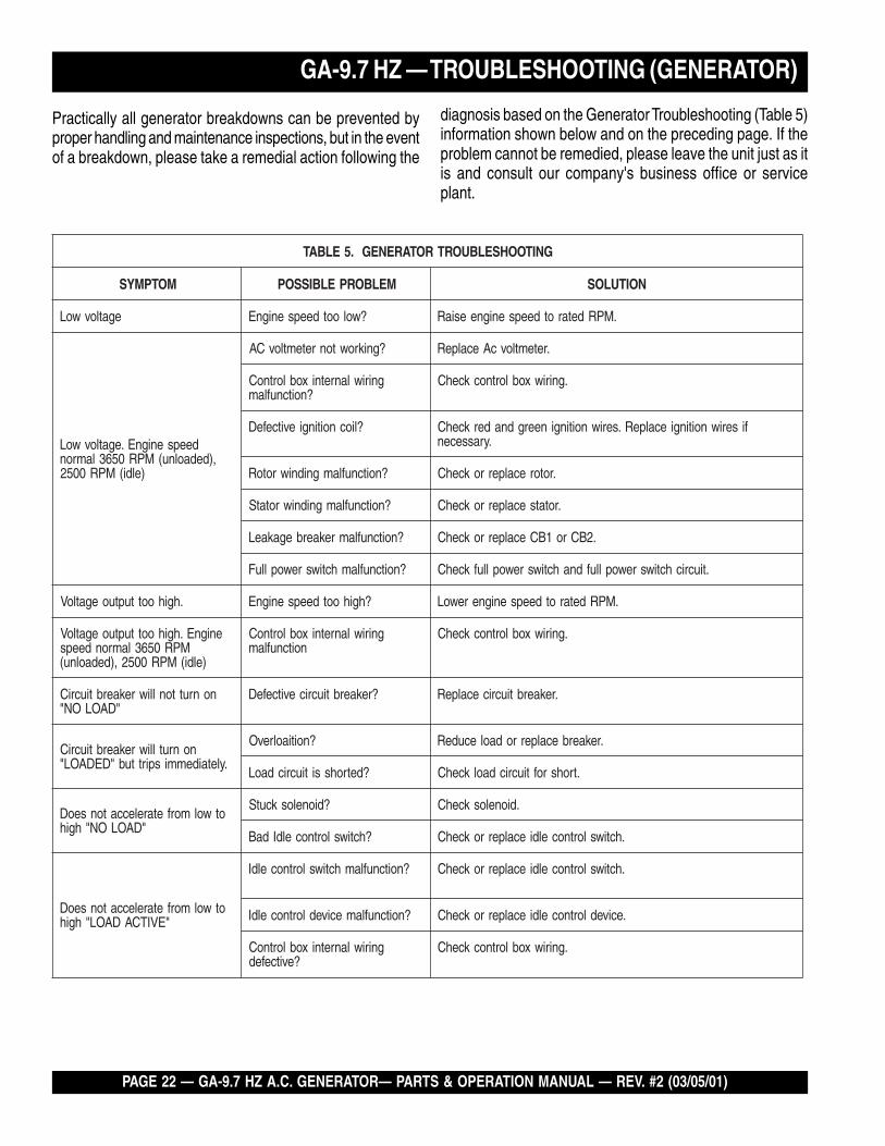
Practically all generator breakdowns can be prevented byproper handling and maintenance inspections, but in the eventof a breakdown, please take a remedial action following the
diagnosis based on the Generator Troubleshooting (Table 5)information shown below and on the preceding page. If theproblem cannot be remedied, please leave the unit just as itis and consult our company's business office or serviceplant.
GNITOOHSELBUORTROTARENEG.5ELBAT
MOTPMYS MELBORPELBISSOP NOITULOS
egatlovwoL ?wolootdeepsenignE .MPRdetarotdeepsenigneesiaR
deepsenignE.egatlovwoL,)dedaolnu(MPR0563lamron
)eldi(MPR0052
?gnikrowtonretemtlovCA .retemtlovcAecalpeR
gniriwlanretnixoblortnoC?noitcnuflam
.gniriwxoblortnockcehC
?liocnoitingievitcefeD fiseriwnoitingiecalpeR.seriwnoitingineergdnaderkcehC.yrassecen
?noitcnuflamgnidniwrotoR .rotorecalperrokcehC
?noitcnuflamgnidniwrotatS .rotatsecalperrokcehC
?noitcnuflamrekaerbegakaeL .2BCro1BCecalperrokcehC
?noitcnuflamhctiwsrewoplluF .tiucrichctiwsrewopllufdnahctiwsrewopllufkcehC
.hgihoottuptuoegatloV ?hgihootdeepsenignE .MPRdetarotdeepsenignerewoL
enignE.hgihoottuptuoegatloVMPR0563lamrondeeps
)eldi(MPR0052,)dedaolnu(
gniriwlanretnixoblortnoCnoitcnuflam
.gniriwxoblortnockcehC
nonruttonlliwrekaerbtiucriC"DAOLON"
?rekaerbtiucricevitcefeD .rekaerbtiucricecalpeR
nonrutlliwrekaerbtiucriC.yletaidemmispirttub"DEDAOL"
?noitiaolrevO .rekaerbecalperrodaolecudeR
?detrohssitiucricdaoL .trohsroftiucricdaolkcehC
otwolmorfetareleccatonseoD"DAOLON"hgih
?dioneloskcutS .dioneloskcehC
?hctiwslortnoceldIdaB .hctiwslortnoceldiecalperrokcehC
otwolmorfetareleccatonseoD"EVITCADAOL"hgih
?noitcnuflamhctiwslortnoceldI .hctiwslortnoceldiecalperrokcehC
?noitcnuflamecivedlortnoceldI .ecivedlortnoceldiecalperrokcehC
gniriwlanretnixoblortnoC?evitcefed
.gniriwxoblortnockcehC

GA-9.7 HZ A.C. GENERATOR — PARTS & OPERATION MANUAL — REV. #2 (03/05/01) — PAGE 23
GA-9.7 HZ — TROUBLESHOOTING (GENERATOR)
)DEUNITNOC(GNITOOHSELBUORTROTARENEG.5ELBAT
MOTPMYS MELBORPELBISSOP NOITULOS
onetarelecedtonseoD."TUPTUOEGATLOV"
?sgnidniwrotorevitcefeD .rotorecalperrokcehC
?dionelosevitcefeD .dionelosecalperrokcehC
?ecivedlortnoceldievitcefeD .ecivedlortnoceldiecalperrokcehC
?dionelosevitcefeD .ecivedlortnoceldiecalperrokcehC
sahtubetarelecedtonseoD."TUPTUOEGATLOV"
?noitcnuflamgniriwxoblortnoC .stnenopmocevitcefedynaecalper,gniriwxoblortnockcehC
?dionelosevitcefeD .dionelosecalperrokcehC
?noitcnuflamecivedlortnoceldI .ecivedlortnoceldiecalperrokcehC

PAGE 24 — GA-9.7 HZ A.C. GENERATOR— PARTS & OPERATION MANUAL — REV. #2 (03/05/01)
How to read the marks and remarks used in this partsbook.
Items Found In the “Remarks” Column
Serial Numbers-Where indicated, this indicates a serialnumber range (inclusive) where a particular part is used.
Model Number-Where indicated, this shows that thecorresponding part is utilized only with this specific modelnumber or model number variant.
Items Found In the “Items Number” Column
All parts with same symbol in the number column, *, #, +, %, or�, belong to the same assembly or kit.
GA-9.7 HZ — EXPLANATION OF CODE IN REMARKS COLUMN
NOTE
If more than one of the same reference number islisted, the last one listed indicates newest (or latest)part available.
NOTE
The contents of this catalog aresubject to change without notice.

GA-9.7 HZ A.C. GENERATOR — PARTS & OPERATION MANUAL — REV. #2 (03/05/01) — PAGE 25
GA-9.7 HZ — SUGGESTED SPARE PARTS
GA-9.7 1 TO 3 UNITS WITH HONDAGX610K1VD ENGINE
1 to 3 UnitsQty. P/N Description4 ............ 0601823204 .......... RECTIFIER4 ............ 0601823754 .......... RELAY1 ............ 0601807459 .......... CIRCUIT BREAKER2 ............ 0601812529 .......... RECEPTABLE1 ............ 0601811032 .......... RECEPTACLE, 250V, 20A2 ............ 0601811031 .......... RECEPTACLE1 ............ 0601812597 .......... RECEPTACLE1 ............ 0601806425 .......... CIRCUIT BREAKER1 ............ 0601806036 .......... CIRCUIT BREAKER4 ............ 0601806424 .......... CIRCUIT BREAKER1 ............ 0601806423 .......... CIRCUIT BREAKER1 ............ 0601830771 .......... IDLE CONTROL SWITCH1 ............ 0601830796 .......... OPERATION SWITCH1 ............ 0663000010 .......... BUTTON STARTER2 ............ 0601802137 .......... FUSE2 ............ 0810105900 .......... CAP FUEL STRAINER1 ............ 0602125032 .......... GAUGE FUEL2 ............ D9312600104 ....... SUSPENSION RUBBER2 ............ 7605419004A........ SUSPENSION RUBBER3 ............ 9807956846 .......... SPARK PLUG3 ............ 15400PR3004 ....... CARTRIDGE FILTER, OIL1 ............ 35480ZJ1812 ........ SWITCH ASSY, OIL LEVEL1 ............ 16100ZJ0892 ........ CARBURETOR ASSY.3 ............ 17010ZJ1000 ........ ELEMENT SET AIR CLEANER2 ............ 16910ZE8015 ....... FILTER COMP FUEL
NOTE
Part numbers on this SuggestedSpare Parts List may supercede/replace the P/N shown in the textpages of this book.

PAGE 26 — GA-9.7 HZ A.C. GENERATOR— PARTS & OPERATION MANUAL — REV. #2 (03/05/01)
GA-9.7 HZ — GENERATOR ASSY.
������������

GA-9.7 HZ A.C. GENERATOR — PARTS & OPERATION MANUAL — REV. #2 (03/05/01) — PAGE 27
GA-9.7 HZ — GENERATOR ASSY.
������������
NO PART NO PART NAME QTY. REMARKS1 A6110200103 ROTOR ASSY. 1 INCLUDES ITEMS W/*1-1* FIELD ASSY. 11-2* 7871025004 RECTIFIER 21-3* 042006304 BEARING .................................... 1 .....................REPLACES 00712063042 A6113100004 FAN 13 A6113400004 SET BOLT, ROTOR 14 0801086104 SET WASHER BEARING 15 0040010000 SPRING WASHER 16 A6136000103 ARMATURE ASSY. 17 A6155100102 END BRACKET 18 A6155000002 END BRACKET 19 A6133300003 COVER, STATOR 110 A6133500004 SET BOLT, STATOR 411 0040008000 SPRING WASHER 412 031108160 PLAIN WASHER .......................... 4 .....................REPLACES 004120800013 7871329514 GROMMET 114 A6155400104 COVER, BEARING 115 0027105012 MACHINE SCREW 316 011008020 HEX, HEAD BOLT ........................ 4 .................... REPLACES 0010108020
0040008000 SPRING WASHER 417 A6155400204 COVER 118 0052205008 RIVET 4

PAGE 28 — GA-9.7 HZ A.C. GENERATOR— PARTS & OPERATION MANUAL — REV. #2 (03/05/01)
GA-9.7 HZ — CONTROL BOX ASSY.
CONTROL BOX ASSY.

GA-9.7 HZ A.C. GENERATOR — PARTS & OPERATION MANUAL — REV. #2 (03/05/01) — PAGE 29
GA-9.7 HZ — CONTROL BOX ASSY.
CONTROL BOX ASSY.
NO PART NO PART NAME QTY. REMARKS1 A6215000103 CONTROL BOX 12 0601850102 GROMMET 2 G-33 8511864604 TERMINAL PLATE 14 0016906020 HEX, HEAD BOLT 55 0601823204 RECTIFIER 5 S5VB606 0027103020 MACHINE SCREW 57 0601823754 RELAY 1 MPR-2TS DC12V8 0027105016 MACHINE SCREW 19 A6225000103 CONTROL PANEL 1 A65121 0000210 0601800258 AC VOLTMETER 1 8283 120V/240V11 0207003000 HEX, NUT 212 0601807459 CIRCUIT BREAKER 1 KM52 2P 265V,35A13 4341817004 BRACKET, CIRCUIT BREAK 114 0027404010 MACHINE SCREW 215 0601812529 RECEPTACLE 1 L14-30R 125/250V,30A,16 0601811032 RECEPTACLE 1 L6-20R 250V,20A,17 0601811031 RECEPTACLE ............................. 1 .......... L5-30R125V,30A, REPLACES 060181103518 0601812597 RECEPTACLE ............................. 2 .......... 5-20R 120V,20A, REPLACES 060181259819 0021004010 MACHINE SCREW 10
0030004000 HEX. NUT................................... 10 .......... REPLACES 020700400020 0601806425 CIRCUIT BREAKER 1 CP32E/30N AC250V,30A21 0601806036 CIRCUIT BREAKER 1 CP32E/20N AC250V,30A22 0601806424 CIRCUIT BREAKER 1 CP31E/30N AC250V,30A23 0601806423 CIRCUIT BREAKER 2 CP31E/20N AC250V,20A24 0027103005 MACHINE SCREW 1025 0601830771 IDLE CONTROL SWITCH 1 S-1B26 0601830796 OPERATION SWITCH 1 ET225N1227 0663000010 START SWITCH .......................... 1 .......... ST-403 REPLACES 060210010228 0601815109 GROUND TERMINAL 1 T-38129 0601823853 IDLE CONTROL DEVICE 1 ND-8030 0021004010 MACHINE SCREW 231 0011305100 HEX. HEAD BOLT ........................ 4 .......... REPLACES 001710501232 0016906020 HEX. HEAD BOLT 432 0601802137 FUSE 2 10A AC250V

PAGE 30 — GA-9.7 HZ A.C. GENERATOR— PARTS & OPERATION MANUAL — REV. #2 (03/05/01)
GA-9.7 HZ — PIPE FRAME ASSY.
PIPE FRAME ASSY.

GA-9.7 HZ A.C. GENERATOR — PARTS & OPERATION MANUAL — REV. #2 (03/05/01) — PAGE 31
GA-9.7 HZ — PIPE FRAME ASSY.
PIPE FRAME ASSY.
NO PART NO PART NAME QTY. REMARKS1 A6418000402 PIPE FRAME 12 A6415100003 FLOOR PANEL 13 A6365000402 FUEL TANK 13-1 0810105900 CAP, FUEL TANK ....................... 1 ........ INCLUDES ITEM W/* REPLACES 08101058003-2* FUEL FILTER 14 3015530004 DRAIN PLUG 15 0150200011 O RING 16 0602125032 FUEL GAUGE 17 011008020 HEX. HEAD BOLT ..................... 4 ......... REPLACES 00171080208 011008020 HEX. HEAD BOLT ...................11 ......... REPLACES 00171080209 A6418700103 BASE 110 D9312600104 RUBBER SUSPENSION 211 0207010000 HEX. NUT 212 7605419004A RUBBER SUSPENSION ........... 2 ......... REPLACES 760541900413 0207010000 HEX. NUT 214 0010110045 HEX. HEAD BOLT 2
0207010000 HEX. NUT 215 0012308030 HEX. HEAD BOLT 216 A6425400303 BRACKET 116-1 A6498200004 LINING 117 0017106016 HEX, HEAD BOLT 818 A6332300204 COVER 119 0017106016 HEX. HEAD BOLT 420 A6418400304 AIR GUIDE 121 0017106016 HEX. HEAD BOLT 222 A6435300003 HANGER 123 0017110025 HEX. HEAD BOLT 424 1622636103Z ROTARY SOLENOID ................ 1 ......... REPLACES 162015040425 1992636004 ARM, SOLENOID 126 011606025 HEX. HEAD BOLT ..................... 1 ......... REPLACES 0010106025
020106050 HEX. NUT .................................. 1 ......... REPLACES 003000600027 A6356600404 WIRE STOPPER 128 0017105010 HEX. HEAD BOLT 129 A6359200503 BRACKET, SOLENOID 130 0207006000 HEX. NUT 231 0010106040 HEX. HEAD BOLT 1
020106050 HEX. NUT .................................. 1 ......... REPLACES 003870600032 0017106016 HEX. HEAD BOLT 433 A6356400303 THROTTLE WIRE 134 0021005010 MACHINE SCREW 135 A6356600304 COVER, SOLENOID 136 0017106016 HEX. HEAD BOLT 437 A6345200204 BATTERY SHEET 138 D1343200204 BATTERY BAND 139 0805082704 BATTERY BOLT 240 0037806000 WING NUT 241 0040006000 SPRING WASH 2 242 952404470 PLAIN WASHER ........................ 2 ......... REPLACES 004120600043 0602220600 TERMINAL CAP (RED) 1
0602220601 TERMINAL CAP (BLK) 144 D1343200604 TERMINAL CAP 145 0019206016 HEX. HEAD BOLT 146 0605513143 HOSE 147 0605515240 HOSE BAND 148 0605515093 HOSE BAND 1

PAGE 32 — GA-9.7 HZ A.C. GENERATOR— PARTS & OPERATION MANUAL — REV. #2 (03/05/01)
GA-9.7 HZ — NAMEPLATE ASSY.
NAMEPLATE ASSY.

GA-9.7 HZ A.C. GENERATOR — PARTS & OPERATION MANUAL — REV. #2 (03/05/01) — PAGE 33
NAMEPLATE ASSY.
NO PART NO PART NAME QTY. REMARKSNAME PLATE ORDER FROM MULTIQUIP SERVICE DEPT. BY
MODEL & SERIAL NUMBER1 0800628504 DECAL; GROUND 1 S-11232 0800696604 DECAL; BATTERY 13 1630645004 DECAL; OIL DRAIN 1 S-14034 7810680104 DECAL; FUEL DRAIN 1 S-30605 8700611804 DECAL; WARNING DANGEROUS 1 S-49846 8700611904 DECAL; DANGER ELECTRICAL 1 S-49857 B9504000304 DECAL; CAUTION HOT PARTS 1 B904000308 D2552000404 DECAL; OPERATING INSTRUCTIONS 1 D25200040B9 0820610804 DECAL; CAUTION! ................................. 1 .......... REPLACES 082061030410 0820610404 DECAL; WARNING! 111 7900636004 DECAL; 3600RPM ONLY 112 8700611524 DECAL; CAUTION OIL LEVEL GAUGE 113 A6562100003 DECAL; MQ MULTIQUIP 9700 2
SEE PAGE 7 FOR DECAL ILLUSTRATIONS.
GA-9.7 HZ — NAMEPLATE ASSY.

PAGE 34 — GA-9.7 HZ A.C. GENERATOR— PARTS & OPERATION MANUAL — REV. #2 (03/05/01)
HONDA GX610K1 ENGINE — CYLINDER HEAD
HONDA GX610K1 ENGINE — CYLINDER HEAD ASSY.
CYLINDER HEAD ASSY.

GA-9.7 HZ A.C. GENERATOR — PARTS & OPERATION MANUAL — REV. #2 (03/05/01) — PAGE 35
CYLINDER HEAD ASSY.
NO PART NO PART NAME QTY. REMARKS1 12210ZJ1000 CYLINDER HEAD COMP., R. ........... 1 ..... INCLUDES ITEMS W/*2 12220ZJ1U80 CYLINDER HEAD COMP., L. ............ 1 ..... INCLUDES ITEMS W/*3* 12205ZE2305 GUIDE, EX. VALVE (OS) 44* 12216ZE2300 CLIP, VALVE GUIDE 45 12251ZJ1003 GASKET, CYLINDER HEAD 26 12311ZJ1000 COVER, HEAD 17 12314ZJ1000 COVER, HEAD FILLER 18 12391ZJ1000 GASKET, HEAD COVER 29 15611921000 CAP, OIL 110 17101ZJ1000 MANIFOLD, IN. 111 17151ZJ1003 GASKET, IN. MANIFOLD 212 90121ZJ1000 BOLT, FLANGE (6X25) (CT200) 813 91301805000 O-RING (26X2.7) 114 92900080250B BOLT, STUD (8X25) 415 9430112200 PIN A, DOWEL (12X20) 416 957010603200 BOLT, FLANGE (6X32) 417 957011007500 BOLT, FLANGE (10X75) 818 957011013000 BOLT, FLANGE (10X130) 219 9807956846 SPARK PLUG (BPR6ES) (NGK) 2
HONDA GX610K1 ENGINE — CYLINDER HEAD ASSY.

PAGE 36 — GA-9.7 HZ A.C. GENERATOR— PARTS & OPERATION MANUAL — REV. #2 (03/05/01)
CYLINDER BARREL ASSY.
HONDA GX610K1 ENGINE — CYLINDER BARREL ASSY.

GA-9.7 HZ A.C. GENERATOR — PARTS & OPERATION MANUAL — REV. #2 (03/05/01) — PAGE 37
CYLINDER BARREL ASSY.
NO PART NO PART NAME QTY. REMARKS1 12000ZJ1810 CYLINDER BARREL ASSY. ....................................... 1 ........... INCLUDES ITEMS W/*2 12356ZJ1000 COVER, BREATHER 13 12358ZJ1000 GASKET, BREATHER COVER 14 12372ZE2300 VALVE, BREATHER 15* 13321ZJ1000 BEARING A, MAIN (BLUE) 1
13322ZJ1000 BEARING B, MAIN (BLACK) 113323ZJ1000 BEARING C, MAIN (BROWN) 1
7 15400PR3004 FILTER, OIL 110 25523VD6010 COLLAR, FILTER SETTING 211 31511ZJ1000 CLAMP, WIRE 112 35480ZJ1812 SWITCH ASSY., OIL LEVEL 115 90014ZE6000 BOLT, FLANGE (6X35) 316 90018PN3000 HOLDER, OIL FILTER 117 90029888000 BOLT, FLANGE (6X16) 218 90031ZE1000 BOLT, FLANGE (6X32) 220* 91201ZJ1003 OIL SEAL (38X58X11) 122 91353671004 O-RING (14MM) 123 9280014000 BOLT, DRAIN PLUG (14MM) 224 9405010000 NUT, FLANGE (10MM) 125 9410914000 WASHER, DRAIN PLUG (14MM) 226 957010607509 BOLT, FLANGE (6X75) 227 961406003010 BEARING, RADIAL BALL (6003) 1
1 120A0ZJ1000 CYLINDER ASSY. 1
HONDA GX610K1 ENGINE — CYLINDER BARREL ASSY.

PAGE 38 — GA-9.7 HZ A.C. GENERATOR— PARTS & OPERATION MANUAL — REV. #2 (03/05/01)
CRANKCASE COVER ASSY.
HONDA GX610K1 ENGINE — CRANKCASE COVER ASSY.

GA-9.7 HZ A.C. GENERATOR — PARTS & OPERATION MANUAL — REV. #2 (03/05/01) — PAGE 39
CRANKCASE COVER ASSY.
NO PART NO PART NAME QTY. REMARKS1 11300ZJ1000 COVER ASSY., CRANKCASE 12 11381ZJ1000 GASKET, CASE COVER 13 12105ZAO701 BOLT, SEALING 14 13321ZJ1000 BEARING A, MAIN (BLUE) 1
13322ZJ1000 BEARING B, MAIN (BLACK) 113323ZJ1000 BEARING C, MAIN (BROWN) 1
5 15120ZJ1000 COVER ASSY., OIL PUMP 16 15124ZJ1003 ROTOR, OIL PUMP (OUTER) 17 15232ZJ1000 SPRING, RELIEF VALVE 18 15348ZJ1000 COVER, OIL FILTER 19 15427ZJ1000 SCREEN, OIL FILTER 110 15655ZJ1000 DIPSTICK, OIL 111 16541ZJ1000 SHAFT, GOVERNOR ARM 112 16542ZJ1000 FORK, GOVERNOR 116 91201ZJ1003 OIL SEAL (38X58X11) 117 91259NM0000 OIL SEAL (10X16X4.5) ..................... 1 ..... REPLACES 9120633300318 91302MB6830 O-RING (13X3.0) 219 93500050100A SCREW, PAN (5X10) 220 9430108140 PIN A, DOWEL (8X14) 221 957010602000 BOLT, FLANGE (6X20) 322 957010805000 BOLT, FLANGE (8X50) 923 9621112000 BALL, STEEL (#12) (3/8) 124 966000601600 BOLT, SOCKET (6X16) 2
HONDA GX610K1 ENGINE — CRANKCASE COVER ASSY.

PAGE 40 — GA-9.7 HZ A.C. GENERATOR— PARTS & OPERATION MANUAL — REV. #2 (03/05/01)
CRANKSHAFT ASSY.
HONDA GX610K1 ENGINE — CRANKSHAFT ASSY.

GA-9.7 HZ A.C. GENERATOR — PARTS & OPERATION MANUAL — REV. #2 (03/05/01) — PAGE 41
HONDA GX610K1 ENGINE — CRANKSHAFT ASSY.
CRANKSHAFT ASSY.
NO PART NO PART NAME QTY. REMARKS3 13310ZJ0880 CRANKSHAFT COMP. 15 90401ZJ1000 WASHER, CRANKSHAFT THRUST 1

PAGE 42 — GA-9.7 HZ A.C. GENERATOR— PARTS & OPERATION MANUAL — REV. #2 (03/05/01)
PISTON ASSY.
HONDA GX610K1 ENGINE — PISTON ASSY.

GA-9.7 HZ A.C. GENERATOR — PARTS & OPERATION MANUAL — REV. #2 (03/05/01) — PAGE 43
HONDA GX610K1 ENGINE — PISTON ASSY.
PISTON ASSY.
NO PART NO PART NAME QTY. REMARKS1 13010ZE8601 RING SET, PISTON (STD) 2
13011ZE8601 RING SET, PISTON (0.25) 213012ZE8601 RING SET, PISTON (0.50) 213013ZE8601 RING SET, PISTON (0.75) 2
2 13101ZJ1000 PISTON 213102ZJ1000 PISTON (0.25) 213103ZJ1000 PISTON (0.50) 213104ZJ1000 PISTON (0.75) 2
3 13111ZJ1000 PIN, PISTON 24 13210ZJ1000 ROD SET, CONNECTING ............................................ 2 ........... INCLUDES ITEM W/*5 13211ZJ1003 BEARING A, CONNECTING ROD (BLUE) 4
13212ZJ1003 BEARING B, CONNECTING ROD (BLACK) 413213ZJ1003 BEARING C, CONNECTING ROD (BROWN) 413214ZJ1003 BEARING D, CONNECTING ROD (GREEN) 413215ZJ1003 BEARING E, CONNECTING ROD 413216ZJ1003 BEARING F CONNECTING ROD 413217ZJ1003 BEARING G CONNECTING ROD 4
6* 13213ML0000 BOLT, CONNECTING ROD 47* 13215KM3000 NUT, CONNECTING ROD 48 9460118000 CLIP, PISTON PIN (18MM) 4

PAGE 44 — GA-9.7 HZ A.C. GENERATOR— PARTS & OPERATION MANUAL — REV. #2 (03/05/01)
CAMSHAFT ASSY.
HONDA GX610K1 ENGINE — CAMSHAFT ASSY.

GA-9.7 HZ A.C. GENERATOR — PARTS & OPERATION MANUAL — REV. #2 (03/05/01) — PAGE 45
CAMSHAFT ASSY.
NO PART NO PART NAME QTY. REMARKS1 12209ZE8003 SEAL, VALVE STEM 22 14100ZJ1801 CAMSHAFT ASSY. ........................................................ 1 ........... INCLUDES ITEM W/*3* 14110ZJ1801 CAMSHAFT COMP. ....................................................... 1 ........... INCLUDES ITEM W/#4 14410ZJ1000 ROD, PUSH 45 14431ZJ1000 ARM, VALVE ROCKER 46 14441ZE2000 LIFTER, VALVE 47 14461ZJ1000 SHAFT, ROCKER ARM 28* 14568ZJ1800 SPRING, WEIGHT RETURN 19* 14569ZJ1801 HOLDER, DECOMPRESSION PIN 210* 145762J1801 PIN A, DECOMPRESSION (7.85) 2
14577ZJ1801 PIN B, DECOMPRESSION (7.95) ................................. 2 ...........REPLACES 14577ZJ180014578ZJ1800 PIN C, DECOMPRESSION (8.05) ................................. 2 ...........REPLACES 14578ZJ180014579ZJ1800 PIN D, DECOMPRESSION (8.15) 214580ZJ1800 PIN E, DECOMPRESSION (8.25) 2
11*# 14581ZJ1801 ROD, DECOMPRESSION 112* 14586ZJ1800 SPRING, DECOMPRESSION PIN HOLDER 213 14711ZJ1000 VALVE, INLET 214 14721ZJ1000 VALVE, EX. 215 14751ZE2003 SPRING VALVE 416 14771ZE2000 RETAINER, IN. VALVE SPRING 417 14775ZE2010 SEAT, VALVE SPRING 218* 16512ZJ1000 HOLDER, GOVERNOR WEIGHT 119* 16522ZJ1000 PLATE, GOVERNOR WEIGHT HOLDER 120* 16523ZJ1000 PIN, GOVERNOR WEIGHT HOLDER 121* 16524ZJ1000 PLATE, GOVERNOR (LOWER) 122* 16529ZJ1000 PLATE, GOVERNOR SLIDER 123* 16531ZJ1003 SLIDER, GOVERNOR 124 90012415000 SCREW, TAPPET ADJ. 425 90206250000 NUT, TAPPET ADJ. 426 90446357000 WASHER, THRUST (17.2MM) 127* 90901ZJ1003 BALL, STEEL (18) 628* 9451017000 CIRCLIP (OUTER) (17MM) 1
HONDA GX610K1 ENGINE — CAMSHAFT ASSY.

PAGE 46 — GA-9.7 HZ A.C. GENERATOR— PARTS & OPERATION MANUAL — REV. #2 (03/05/01)
RECOIL STARTER ASSY.
HONDA GX610K1 ENGINE — RECOIL STARTER ASSY.

GA-9.7 HZ A.C. GENERATOR — PARTS & OPERATION MANUAL — REV. #2 (03/05/01) — PAGE 47
HONDA GX610K1 ENGINE — RECOIL STARTER ASSY.RECOIL STARTER ASSY.
NO PART NO PART NAME QTY. REMARKS1 28400ZE3W01ZA STARTER ASSY., RECOIL R8 (BRT. RED) 1 INCLUDES ITEMS W/*2* 28410ZE3W01ZA CASE COMP. RECOIL STARTER R8 (BRT RED) 13* 28421ZE3W01 PULLEY, RECOIL STARTER 14* 28422ZE2W01 RATCHET STARTER 25* 28441ZE2W01 SPRING, FRICTION 16* 28442ZE2W01 SPRING, STARTER RETURN 17* 28443ZE2W01 SPRING, RATCHET 28* 28444ZE2W01 RETAINER, SPRING 19* 28445ZE2W01 HOLDER, SPRING 110* 28461ZE2W01 GRIP, STARTER 111* 28462ZH8003 ROPE, RECOIL STARTER ...................................... 1 .... REPLACES 28462ZE3W0112* 28469ZE2W01 GRIP, REINFORCEMENT 113* 90004ZE2W01 SCREW, CENTER 114 957010600800 BOLT, FLANGE (6X8) 3

PAGE 48 — GA-9.7 HZ A.C. GENERATOR— PARTS & OPERATION MANUAL — REV. #2 (03/05/01)
HONDA GX610K1 ENGINE — FAN COVER ASSY.FAN COVER ASSY.

GA-9.7 HZ A.C. GENERATOR — PARTS & OPERATION MANUAL — REV. #2 (03/05/01) — PAGE 49
HONDA GX610K1 ENGINE — FAN COVER ASSY.FAN COVER ASSY.
NO PART NO PART NAME QTY. REMARKS2 19611ZJ1800ZB COVER, FAN R8 (RECOIL STARTER)(BRT.RED) 14 19612ZJ1000 PLATE, R. SIDE 15 19614ZJ1000 PLATE, L SIDE 16 19615ZJ1000 HOOD FAN COVER 17 19617ZJ4000 COVER, R. SIDE PLATE 110 19631ZJ1000 SHROUD, R. 111 19632ZJ1000 SHROUD, L. 112 28405ZJ1801ZB SPACER, RECOIL START MOUNT R8 (BRT RED)) 113 33713GC2000 COLLAR B,TAILLIGHT 616 90013883000 BOLT, FLANGE (6X12) 817 90018ZE1000 BOLT, FLANGE (6X23) 218 90042ZJ1000 BOLT, STUD (6X75) 419 90055ZE1000 SCREW, TAPPING (4X6) 320 90104GF6000 BOLT, FLANGE (6X20) 221 90113GE4000 BOLT, FLANGE (6MM) (BLACK) 224 90683SD9781 CLIP (20MM) 125 9405006000 NUT, FLANGE (6MM) 426 957010600800 BOLT, FLANGE (6X8) 2

PAGE 50 — GA-9.7 HZ A.C. GENERATOR— PARTS & OPERATION MANUAL — REV. #2 (03/05/01)
CARBURETOR ASSY.
HONDA GX610K1 ENGINE — CARBURETOR ASSY.

GA-9.7 HZ A.C. GENERATOR — PARTS & OPERATION MANUAL — REV. #2 (03/05/01) — PAGE 51
CARBURETOR ASSY.
NO PART NO PART NAME QTY. REMARKS1 12357ZJ1000 TUBE, BREATHER 12 15772551000 CLIP, BREATHER TUBE 13*# 16010ZG8000 GASKET SET 14* 16011382004 VALVE SET, FLOAT ...................................... 1 .......... REPLACES 16011GK08915* 16013ZV4005 FLOAT SET 16* 16015ZJ1000 CHAMBER SET, FLOAT ............................... 1 .......... INCLUDES ITEMS W/#7 16016ZJ1010 SCREW SET 18*# 16024124760 SCREW SET,DRAIN 19* 16028ZG8000 SCREW SET 110* 16081ZV4650 SCREW-WASHER 411 16100ZJ0892 CARBURETOR ASSY. (BG21E B) ............... 1 .......... INCLUDES ITEMS W/*12* 16148141881 CAP, CHOKE LEVER DUST 113* 16151ZJ0020 JET SET (#60) 114* 16166ZJ1010 NOZZLE, MAIN ............................................. 1 .......... REPLACES 16166ZJ000015* 16178548004 O-RING (5.8X1.9) 116* 16200ZJ1003 VALVE ASSY., SOLENOID 117 16211ZJ1000 INSULATOR, CARBURETOR 118 16221ZG8000 GASKET, CARBURETOR 219 17228ZG8003 GASKET, AIR CLEANER 120 17410ZJ1000 ELBOW COMP., AIR CLEANER ................... 1 .......... INCLUDES ITEMS W/++21++ 19024ZA0000 COLLAR, DISTANCE 222 90682959661 CLIP B, CABLE 123* 938920501218 SCREW-WASHER (5X12) 224 9500202080 CLIP, TUBE (B8) 125 950054546020 BULK HOSE, VAC (4.5X460) 126 958010610508 BOLT, FLANGE (6X10⁵) 227* 99201ZG80880 JET SET, MAIN (#88) 1
99201ZG80820 JET SET, MAIN (#82 HIGH ALTITUDE) 199201ZG80850 JET SET, MAIN (#85 HIGH ALTITUDE) 1
HONDA GX610K1 ENGINE — CARBURETOR ASSY.

PAGE 52 — GA-9.7 HZ A.C. GENERATOR— PARTS & OPERATION MANUAL — REV. #2 (03/05/01)
AIR CLEANER ASSY.
HONDA GX610K1 ENGINE — AIR CLEANER ASSY.

GA-9.7 HZ A.C. GENERATOR — PARTS & OPERATION MANUAL — REV. #2 (03/05/01) — PAGE 53
AIR CLEANER ASSY.
NO PART NO PART NAME QTY. REMARKS1 17010ZJ1000 ELEMENT SET, AIR CLEANER ................... 1 .......... INCLUDES ITEMS W/*2* 17216ZJ1000 GASKET A, ELEMENT 13* 17217ZJ1000 GASKET B, ELEMENT 14 17218ZJ1000 FILTER (OUTER) 15 17220ZJ1000 HOUSING COMP., AIR CLEANER 16 17231ZJ1000 COVER, AIR CLEANER 17 17232ZJ1000 GROMMET, AIR CLEANER 18 17237ZJ1000 HOSE, AIR CLEANER 19 17251ZJ1000 TUBE, AIR CLEANER CONN. 110 17255758000 BAND, AIR CLEANER CONN. TUBE 111 17257HB3000 BAND, AIR CLEANER (B) 113 90017ZJ1000 BOLT, AIR CLEANER 114 90018ZE1000 BOLT, FLANGE (6X23) 315 90120102000 COLLAR, AIR CLEANER HOUSING 416 93500040200A SCREW, PAN (4X20) 117 93500040250G SCREW, PAN (4X25) 118 938910501608 SCREW, WASHER 219 957000601800 BOLT, FLANGE (6X18) ................................ 1 .......... REPLACES 957010601800
HONDA GX610K1 ENGINE — AIR CLEANER ASSY.

PAGE 54 — GA-9.7 HZ A.C. GENERATOR— PARTS & OPERATION MANUAL — REV. #2 (03/05/01)
HONDA GX610K1 ENGINE — MUFFLER ASSY.MUFFLER ASSY.

GA-9.7 HZ A.C. GENERATOR — PARTS & OPERATION MANUAL — REV. #2 (03/05/01) — PAGE 55
MUFFLER ASSY.
NO PART NO PART NAME QTY. REMARKS1 MUFFLER KIT 1 NOT AVAILABLE, SEE COMPONENTS2 18310ZJ1000 MUFFLER COMP. ............................. 1 ..... 18310ZJ10033 18321ZJ1000 PROTECTOR,MUFFLER ................ 1 ..... 18321ZJ10034 18330ZJ1601 PIPE COMP., EX. 15 18333ZJ1000 STAY, MUFFLER .............................. 1 ..... 18338ZJ10036 18396ZJ1003 BAND ASSY. 17 957010600800 BOLT, FLANGE (6X8) 68 957010801400 BOLT, FLANGE (8X14) 49 957010802000 BOLT, FLANGE (8X20) 410 18333ZJ1000 GASKET,EX,PIPE 211 99405008000 NUT,FLANGE(8mm) 4
HONDA GX610K1 ENGINE — MUFFLER ASSY.

PAGE 56 — GA-9.7 HZ A.C. GENERATOR— PARTS & OPERATION MANUAL — REV. #2 (03/05/01)
FUEL PUMP ASSY.
HONDA GX610K1 ENGINE — FUEL PUMP ASSY.

GA-9.7 HZ A.C. GENERATOR — PARTS & OPERATION MANUAL — REV. #2 (03/05/01) — PAGE 57
FUEL PUMP ASSY.
NO PART NO PART NAME QTY. REMARKS1 16700ZJ1003 PUMP ASSY., FUEL 12 16711ZJ1800 STAY, FUEL PUMP 14 16910ZE8015 STRAINER COMP., FUEL 15 19905ZA8701 GROMMET, WIRE 16 35806752630 BASE, CLIP 17 90617SA0003 CLIP, WIRE HARNESS 18 950014511040 BULK HOSE, FUEL (4.5X110) 19 950015519540 BULK HOSE, FUEL (5.5X195) 110 950015521540 BULK HOSE, FUEL (5.5X215) 111 9500202080 CLIP, TUBE (B8) 212 950024105008 CLIP, TUBE (10.5MM) 413 950033601620 TUBE, VINYL (11X13X160) 114 957010600800 BOLT, FLANGE (6X8) 215 957010601400 BOLT, FLANGE (6X14) 2
HONDA GX610K1 ENGINE — FUEL PUMP ASSY.

PAGE 58 — GA-9.7 HZ A.C. GENERATOR— PARTS & OPERATION MANUAL — REV. #2 (03/05/01)
FLYWHEEL ASSY.
HONDA GX610K1 ENGINE — FLYWHEEL ASSY.

GA-9.7 HZ A.C. GENERATOR — PARTS & OPERATION MANUAL — REV. #2 (03/05/01) — PAGE 59
FLYWHEEL ASSY.
NO PART NO PART NAME QTY. REMARKS1 19511ZJ1000 FAN, COOLING 13 28451ZJ1801 PULLEY, STARTER 16 28453ZJ1801 SPACER, STARTER PULLEY MT. 18 31110ZJ1811 FLYWHEEL COMP. 110 90013ZJ1800 BOLT, UBS (12X28) 111 90201ZG3000 NUT, FLANGE (20MM) 112 90401ZG3000 WASHER (20MM) 113 90741ZE2000 KEY, SPECIAL WOODRUFF (25X18) 115 957010801600 BOLT, FLANGE (8X16) 3
HONDA GX610K1 ENGINE — FLYWHEEL ASSY.

PAGE 60 — GA-9.7 HZ A.C. GENERATOR— PARTS & OPERATION MANUAL — REV. #2 (03/05/01)
HONDA GX610K1 ENGINE — IGNITION COIL ASSY.IGNITION COIL ASSY.

GA-9.7 HZ A.C. GENERATOR — PARTS & OPERATION MANUAL — REV. #2 (03/05/01) — PAGE 61
IGNITION COIL ASSY.
NO PART NO PART NAME QTY. REMARKS1 30500ZJ1013 COIL ASSY., R. IGNITION 12 30518ZJ1000 GROMMET, IGNITION WIRE 23 30550ZJ1013 COIL ASSY., L. IGNITION 14 30700ZJ1003 CAP ASSY., NOISE SUPPRESSER 25 31630ZJ1003 COIL ASSY., CHARGE (12V/3A) 17 31740ZJ1003 DIODE ASSY., ENGINE STOP 18 63312ZA7000 GROMMET, TOOL 19 90014ZE6000 BOLT, FLANGE (6X35) 211 901219052000 BOLT, FLANGE (6X25) 212 90658SA0003 CLIP, WIRE HARNESS 113 90673GJ5003 CLIP, CORD 114 901504750003 CLIP, WIRE HARNESS 115 957010600800 BOLT, FLANGE (6X8) 1
HONDA GX610K1 ENGINE — IGNITION COIL ASSY.

PAGE 62 — GA-9.7 HZ A.C. GENERATOR— PARTS & OPERATION MANUAL — REV. #2 (03/05/01)
STARTER MOTOR ASSY.
HONDA GX610K1 ENGINE — STARTER MOTOR ASSY.

GA-9.7 HZ A.C. GENERATOR — PARTS & OPERATION MANUAL — REV. #2 (03/05/01) — PAGE 63
STARTER MOTOR ASSY.
NO PART NO PART NAME QTY. REMARKS1 31200ZJ1004 MOTOR ASSY., STARTER 12 31243ZJ1800 BRACKET, STARTER MAGNETIC SET. 13 32402ZJ1810 CABLE, MAGNET SWITCH ............................. 1 ......... INCLUDES ITEMS W/*4* 32411KB9930 COVER A, MAGNETIC SWITCH 15* 32411402000 COVER, STARTER. MOTOR TERMINAL 16 35850ZJ1811 SWITCH ASSY., STARTER MAGNETIC 17 9405006000 NUT, FLANGE (6MM) 28 9407006080 NUT, WASHER (6MM) 29 9430110120 PIN, DOWEL (10X12) 210 957010811000 BOLT, FLANGE (8X10) 2
HONDA GX610K1 ENGINE — STARTER MOTOR ASSY.

PAGE 64 — GA-9.7 HZ A.C. GENERATOR— PARTS & OPERATION MANUAL — REV. #2 (03/05/01)
HONDA GX610K1 ENGINE — GOVERNOR/CONTROL ASSY.GOVERNOR/CONTROL ASSY.

GA-9.7 HZ A.C. GENERATOR — PARTS & OPERATION MANUAL — REV. #2 (03/05/01) — PAGE 65
GOVERNOR/CONTROL ASSY.
NO PART NO PART NAME QTY. REMARKS1 16263ZE3790 JOINT, ROD 12 16265ZJ1U80 STAY ASSY., AUTO THROTTLE ...... 1 ............ INCLUDES ITEMS W/*3 16500ZJ1U80 CONTROL ASSY. ............................. 1 ............ INCLUDES ITEMS W/# #4+ 16534ZJ1U80 SPRING, RETURN 15 16534Z16680 SPRING, STARTER 16 16550ZJ1U80 ARM COMP., GOVERNOR............... 1 ........... INCLUDES ITEMS W/+8 16555ZJ1000 ROD, GOVERNOR 19# 16561ZG1000 SPRING, GOVERNOR 110 16561ZJ1000 SPRING, GOVERNOR 111 16562ZJ1000 SPRING, THROTTLE RETURN 113# 16574ZE1000 SPRING, LEVER 114# 16575ZH8000 WASHER, CONTROL LEVER 115*# 16576891000 HOLDER, CABLE 116# 16578ZE1000 SPACER, CONTROL LEVER 117# 16584883300 SPRING, CONTROL ADJ. 218* 16592ZJ1000 SPRING, CABLE RETURN 121# 16628ZJ1000 ROD, CHOKE KNOB 122# 16649ZJ1000 HOLDER, CHOKE KNOB 123# 17951ZG1000 KNOB, CHOKE 124 90013883000 BOLT, FLANGE (6X12) 225 90015ZE3790 BOLT, GOVERNOR ARM 126# 90114SA0000 NUT, SELFLOCK (6MM) 127* 90605230000 CIRCLIP (5MM) 228* 9350004006OH SCREW, PAN (4X6) 229# 9350005012OH SCREW, PAN (5X12) 130# 9350005025OH SCREW, PAN (5X25) 231# 93500050160A SCREW, PAN (5X16) 232*+ 93500050300H SCREW, PAN (5X30) 234 9405006000 NUT, FLANGE (6MM) 1
HONDA GX610K1 ENGINE — GOVERNOR/CONTROL ASSY.

PAGE 66 — GA-9.7 HZ A.C. GENERATOR— PARTS & OPERATION MANUAL — REV. #2 (03/05/01)
HONDA GX610K1 ENGINE — LABELSLABELS

GA-9.7 HZ A.C. GENERATOR — PARTS & OPERATION MANUAL — REV. #2 (03/05/01) — PAGE 67
HONDA GX610K1 ENGINE — LABELSLABELS
NO PART NO PART NAME QTY. REMARKS1 87101ZJ0000 MARK, EMBLEM (GX610) 12 87152ZJ0000 LABEL, SPECIFICATION (GX610) 13 87522ZJ1000 LABEL, CAUTION 15 87532ZH8810 MARK, OIL ALERT (E) 1

PAGE 68 — GA-9.7 HZ A.C. GENERATOR— PARTS & OPERATION MANUAL — REV. #2 (03/05/01)
HONDA GX610K1 ENGINE —GASKET KIT
GASKET KIT
NO PART NO PART NAME QTY. REMARKS061A1ZJ1000 GASKET KIT ..................................... 1 ........... INCLUDES ITEMS W/*1 11381ZJ1000 GASKET, CASE COVER 1
2* 12251ZJ1003 GASKET, CYLINDER HEAD 23* 12358ZJ1000 GASKET, BREATHER COVER 14* 12391ZJ1000 GASKET, HEAD COVER 25* 16221ZG8000 GASKET, CARBURETOR 26* 17151ZJ1003 GASKET, IN. MANIFOLD 27* 17228ZG8003 GASKET, AIR CLEANER 18* 18333ZJ1000 GASKET, EX. PIPE 29* 91301805000 ORING (26X2.7) 1

GA-9.7 HZ A.C. GENERATOR — PARTS & OPERATION MANUAL — REV. #2 (03/05/01) — PAGE 69
PAYMENT TERMS
Terms of payment for parts are net 10 days.
FREIGHT POLICY
All parts orders will be shipped collect orprepaid with the charges added to the invoice.All shipments are F.O.B. point of origin.Multiquip’s responsibility ceases when a signedmanifest has been obtained from the carrier,and any claim for shortage or damage must besettled between the consignee and the carrier.
MINIMUM ORDER
The minimum charge for orders from Multiquipis $15.00 net. Customers will be asked forinstructions regarding handling of orders notmeeting this requirement.
RETURNED GOODS POLICY
Return shipments will be accepted and creditwill be allowed, subject to the followingprovisions:
1. A Returned Material Authorization mustbe approved by Multiquip prior to shipment.
2. To obtain a Return Material Authorization,a list must be provided to Multiquip PartsSales that defines item numbers,quantities, and descriptions of the items tobe returned.
a. The parts numbers and descriptionsmust match the current parts pricelist.
b. The list must be typed or computergenerated.
c. The list must state the reason(s) forthe return.
d. The list must reference the salesorder(s) or invoice(s) under whichthe items were originally purchased.
e. The list must include the name andphone number of the personrequesting the RMA.
3. A copy of the Return MaterialAuthorization must accompany the returnshipment.
PRICING AND REBATES
Prices are subject to change without priornotice. Price changes are effective on a specificdate and all orders received on or after that datewill be billed at the revised price. Rebates forprice declines and added charges for priceincreases will not be made for stock on hand atthe time of any price change.
Multiquip reserves the right to quote and selldirect to Government agencies, and to OriginalEquipment Manufacturer accounts who useour products as integral parts of their ownproducts.
SPECIAL EXPEDITING SERVICE
A $20.00 to $50.00 surcharge will be added tothe invoice for special handling including busshipments, insured parcel post or in caseswhere Multiquip must personally deliver theparts to the carrier.
LIMITATIONS OF SELLER’S LIABILITY
Multiquip shall not be liable here under fordamages in excess of the purchase price of theitem with respect to which damages are claimed,and in no event shall Multiquip be liable for lossof profit or good will or for any other special,consequential or incidental damages.
LIMITATION OF WARRANTIES
No warranties, express or implied, are made inconnection with the sale of parts or tradeaccessories nor as to any engine notmanufactured by Multiquip. Such warrantiesmade in connection with the sale of new,complete units are made exclusively by astatement of warranty packaged with suchunits, and Multiquip neither assumes notauthorizes any person to assume for it anyother obligation or liability whatever inconnection with the sale of its products. A partfrom such written statement of warranty, thereare no warranties, express, implied or statutory,which extend beyond the description of theproducts on the face hereof.
4. Freight is at the sender’s expense. Allparts must be returned freight prepaid toMultiquip’s designated receiving point.
5. Parts must be in new and resalablecondition, in the original Multiquip package(if any), and with Muiltiquip part numbersclearly marked.
6. The following items are not returnable:
a. Obsolete parts. (If an item is listedin the parts price book as beingreplaced by another item, it isobsolete.)
b. Any parts with a limited shelf life(such as gaskets, seals, “O” rings,and other rubber parts) that werepurchased more than six monthsprior to the return date.
c. Any line item with an extended dealernet price of less than $5.00.
d. Special order items.
e. Electrical components.
f. Paint, chemicals, and lubricants.
g. Decals and paper products.
h. Items purchased in kits.
7. The sender will be notified of any materialreceived that is not acceptable.
8. Such material will be held for 5 workingdays from notification, pendinginstructions. If a reply is not receivedwithin 5 days, the material will be returnedto the sender at his expense.
9. Credit on returned parts will be issued atdealer net price at time of the originalpurchase, less a 15% restocking charge.
10. In cases where an item is accepted forwhich the original purchase documentcan not be determined, the price will bebased on the list price that was effectivetwelve months prior to the RMA date.
11. Credit issued will be applied to futurepurchases only.
Effective: July 1, 2000 TERMS AND CONDITIONS OF SALE — PARTS

PARTS AND OPERATION MANUAL
Manufactured for MULTIQUIP INC.byDENYO MANUFACTURING CO., USA
HERE'S HOW TO GET HELPPLEASE HAVE THE MODEL AND SERIAL NUMBERON-HAND WHEN CALLING
PARTS DEPARTMENT800/427-1244 or 310/537-3700FAX: 800/672-7877 or 310/637-3284
SERVICE DEPARTMENT800/478-1244 or 310/537-3700FAX: 310 - 537-4259
WARRANTY DEPARTMENT800/421-1244, EXT. 279 or 310/537-3700FAX: 310 - 537-1173
MAIN800/421-1244 or 310/537-3700FAX: 310 - 537-3927
MULTIQUIP INC.POST OFFICE BOX 6254CARSON, CA 90749310-537-3700 • 800-421-1244FAX: 310-537-3927E-MAIL: [email protected]: multiquip.com
Atlanta • Boise • Dallas • Houston • NewarkQuebec, Canada • Manchester, UK • Rio De Janiero, BR • Guadalajara, MX