
MULTIPROCESSOR BASED REAL-TIME DATA ACQUISITION...
20
MULTIPROCESSOR BASED REAL- TIME DATA ACQUISITION SYSTEMS Item Type text; Proceedings Authors Noriega, Gerardo Publisher International Foundation for Telemetering Journal International Telemetering Conference Proceedings Rights Copyright © International Foundation for Telemetering Download date 13/06/2018 12:10:15 Link to Item http://hdl.handle.net/10150/608903
Transcript of MULTIPROCESSOR BASED REAL-TIME DATA ACQUISITION...

MULTIPROCESSOR BASED REAL-TIME DATA ACQUISITION SYSTEMS
Item Type text; Proceedings
Authors Noriega, Gerardo
Publisher International Foundation for Telemetering
Journal International Telemetering Conference Proceedings
Rights Copyright © International Foundation for Telemetering
Download date 13/06/2018 12:10:15
Link to Item http://hdl.handle.net/10150/608903
MULTIPROCESSOR BASED REAL-TIME DATAACQUISITION SYSTEMS
Gerardo Noriega, R&D ManagerRMS INSTRUMENTS LTD.
1415-2 Bonhill Road, Mississauga, Ontario, Canada, L5T-1R2
ABSTRACT Equipment for data collection and recording has widespread use ina variety of engineering applications. This paper deals with the use ofmultiprocessor-based architectures in digital data acquisition systems,emphasizing advantages in terms of flexibility and overall system throughput, andthe characteristics of the embedded operating system.
An overview of the basic architecture of typical data acquisition systems isfirst presented, followed by a description of a multiprocessing architecture for dataacquisition in real-time environments where multiple sampling rates are employedto monitor analog and digital data from different sources. Software and hardwaretechniques are covered, including the multiplexing of analog signals, digital signalprocessing, use of masking techniques in the processing of serial data streams,and the use of multi-point buses for communications with peripheral devices.
The characteristics of a real-time multi-tasking operating system areanalysed. This is the core of the software in any data acquisition system whichmust meet real-time constraints. In turn, the core of the operating system is thereal-time kernel. Emphasis is put into the organization of the kernel, coveringissues such as kernel primitives, service calls, interrupt service routines, processscheduling, memory management, and communications and synchronizationbetween processes.
1. Introduction
The data acquisition system (DAS) is often the central component ofcomplex engineering and scientific systems for data collection and analysis. Itsbasic tasks are the collection, distribution, monitoring, pre-processing, andrecording of data. The system must be capable of handling data which is receiveddirectly in digital form, as well as analog signals which must first be converted intodigital form. Depending on the type of application, multiple sampling rates mayhave to be used, so non-critical signals may be sampled at lower rates to avoid

unnecessary overhead. Also of great importance is the ease with which theconfiguration of the system may be modified to handle different applications.
The basic characteristics described above for a digital DAS must beachieved in a real-time environment, that is, the correctness of the computationsinvolved depends not only on the logical results, but on the system meetingcertain timing constraints to produce these results [1].
Applications will continue to become more demanding and sophisticated.The conventional approach is to use faster processors as a quick solution to thedemand for more speed, and to modify the software to meet new functionalrequirements. Clearly this is a very limiting approach, since there exist practicallimits to processor speeds, and maintenance of large software packages is verycostly.
In this paper we deal with architectures based on multiple processors, eachdedicated to handle a specific task of the data acquisition process. Thisintroduces a basic form of parallelism which increases system throughput, and italso allows for greater system flexibility and ease of maintenance bydecentralizing the software. We give special attention to the operating system, thecore of the software, which provides services to the application program and theinterface to the hardware. The operating system must allow multi-tasking andprovide features such as “preemption”, necessary in real-time environments.Specialized operating systems are required to meet these needs: although anexcellent platform for program development and general application programs,personal computers with the conventional DOS (disk operating system) are notwell suited for real-time multi-tasking applications.
The outline of the paper is as follows. In Section II we first overview thebasic organization of typical DASs, and then present a multiprocessingarchitecture for data acquisition, describing in detail some critical software andhardware issues involved. In Section III we discuss general requirements of theembedded real-time operating system, and describe one such system designed atRMS INSTRUMENTS LTD. specifically for real-time data acquisitioninstrumentation. Conclusions are presented in Section IV.
II. A Multiprocessing Architecture for Data Acquisition
A. Basic Organization of Data Acquisition Systems
The definition of a DAS can be quite flexible. For our purposes it refers to aself-contained subsystem which includes the hardware and software involved in
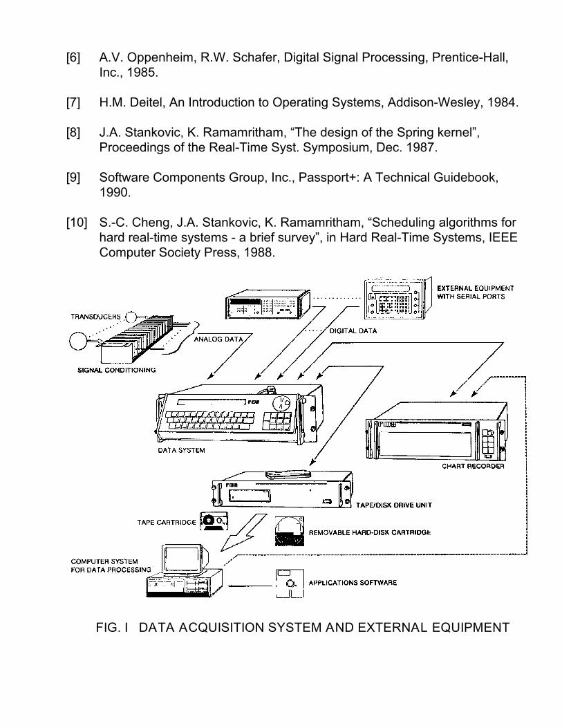
the sampling and analog-to-digital (A/D) conversion of analog signals, acquisitionof data directly in digital form, digital signal processing prior to data recording,real-time monitoring, organization of data into structured blocks, and the recordingof these blocks in disk and/or tape. The basic structure of one such system isillustrated in Fig.1.
As shown in Fig.1, there is usually a central unit in the system whichhandles most of the data acquisition functions. This accepts analog and digitalsignals from the exterior, and has interfaces to communicate with monitoring (e.g.,chart recorder) and storage devices (e.g., disk, tape drives), which are also anintegral part of the DAS.
The permanent record on paper and high resolution provided by the chartrecorder render it ideal for real-time monitoring. With regard to data storage onmagnetic media, it is possible to record on disk, on tape, or simultaneously ondisk and tape, thus achieving an implied redundancy.
In specialized applications the DAS is often fine-tuned and fully dedicated tothe data acquisition tasks, and general purpose computers are used in theanalysis and processing stages. By recording data on disk in a standard format itis possible to have direct access to it from the data processing computer; at thesame time, this gives the user ample choice from a plethora of applicationssoftware available in the market. On the other hand, tape cartridges provide theuser with a transportable medium which is ideal for field applications, or cansimply be used as a back-up system. A third option is that of removable hard disktechnology; this provides the user with the advantage of direct access from thedata processing computer, and that of transferability.
B. Multiprocessing Architecture
The objective of the architecture discussed here is to distribute efficientlyamongst different processors the computational tasks of the DAS. The criterionused to distribute this load is a functional one, e.g., all tasks associated withsampling, A/D conversion, and digital signal processing of analog signals may beassigned to a processor. This approach clearly introduces a form of parallelismthat increases overall system throughput; the concept is of course fully compatiblewith the exploitation of the parallelism inherent in some algorithms, which leads toimplementations in arrays of processors [2]. Flexibility is gained through smaller,easier to maintain programs running in the individual processors.
Fig.2 illustrates a multiprocessor based architecture for a DAS. To simplifythe discussion, we limit ourselves to a basic system that interfaces to analog

signals and asynchronous serial data (RS232/422/485). The core of the system isthe main CPU (central processing unit). This takes care of: a) providing the userwith an environment to develop system configurations or “programs”, b) set-upand coordination of the activities of the different processors, c) handling of datatransfers to and from processors, and d) providing a suitable operator interface.As we shall discuss in detail in Section III, an underlying operating system mustensure compliance with real-time constraints.
The operator interface can be efficiently handled via an intelligentkeyboard/display unit with a serial (RS232) link to communicate with the mainCPU. Also, capability for remote set-up and control of the DAS is a desirablefeature. A standard interface such as IEEE-488 is commonly used.
The dedicated processors control peripheral modules. These usuallycommunicate with the main CPU via a standard bus such as STD or VME [2]. Forthe DAS assumed we have a multichannel A/D module, a digital (serial) module toreceive and transmit asynchronous serial data via multiple channels, a tape/diskcontroller, and a chart recorder controller. Communications with the tape and diskdrives are best managed with a fast multi-point bus for peripheral devices such asthe Small Computer System Interface (SCSI) ([3]; see also Section II.C). A simpleRS232 or parallel (centronics-type) interface is suitable to control the chartrecorder.
The chart recorder itself is an excellent tool which provides high resolutionreal-time data monitoring with a permanent record on paper. An intelligentrecorder of the thermal-array type will significantly ease the tasks of the mainCPU. It should provide for easy channel positioning and scaling, wide frequencyresponse, adequate chart speeds, and flexible chart annotation. Additionalfeatures such as different trace drawing algorithms, programmable self-generatingbackground grid patterns, and math capabilities will further enhance the systemoverall. The chart recorder can normally operate as a stand-alone unit or undercontrol of a host computer: it is a versatile instrument which does not have to bepermanently attached to the DAS.
In the following sections we will discuss in some detail the characteristics ofthe individual peripheral modules.
A/D Module
The output of analog sensors or transducers must first go through a signalconditioning stage. This is an analog-to-analog operation which includes functionssuch as: a) amplification, b) impedance transformation, c) isolation, d) removal of

common mode noise, e) filtering, f) current to voltage conversion, g) frequency tovoltage conversion, and h) thermocouple and RTD interfacing. Signal conditioningdevices are commercially available in a variety of packages, and are oftenhandled independently of the DAS itself. The conditioned analog signal must beband-limited. This is accomplished through an antialiasing filter, which issometimes considered as part of the signal conditioning stage.
A number of different approaches are available to handle multiple channels[4]. With “analog multiplexing”, the multiplexing occurs immediately after the signalconditioners, and single sample and hold (S&H) and analog-to-digital converter(ADC) circuits are shared amongst all channels. This approach is inexpensive,and use of a common ADC ensures that all channels suffer similar conversionerrors due to tolerances in the device specifications. Disadvantages include lowthroughput (conversions must be performed sequentially), cross-talk betweenchannels, and the fact that samples for different channels do not correspond tothe same point in time. A second technique uses “digital multiplexing”, withindividual S&H circuits and ADCs. Although more costly and voluminous, thisapproach is clearly faster (conversions are performed simultaneously), and it hasbecome quite common with the decreasing price of ADCs. Other intermediateapproaches are also possible, where for example, individual S&H circuits areused, but a single ADC is shared between channels.
System specifications will determine important issues in the A/D module, such as:
a) Number of channels handled by each A/D module.
b) Type of ADC to be used: successive approximations, flash, subranging,integrating, sigma-delta.
c) Resolution, conversion time, signal-to-noise ratio.
In terms of resolution and conversion time, the state of the art is [5]:22 bits ---- 1 Ksample/sec20 " ---- 4 "18 " ---- 50 "16 " ---- 500 "14 bits ---- 10 Msample/sec12 " ---- 25 "10 " ---- 75 "8 " ---- 500 "

The RMS quantization noise in the Nyquist band Fs/2 for an ideal ADC isq//12. Defining the signal-to-noise ratio (SNR) as the ratio of the RMS levelof a full-scale sine wave to the RMS quantization noise of an ideal N-bitADC (over the Nyquist band), we have:
SNR = 6.02N + 1.76 [dB] . (1)
From this follows a practical “rule of thumb”: increasing the resolution of theADC by 1 bit results roughly in a 6 dB improvement in the SNR.
A more practical interpretation of the SNR, especially when comparingmanufacturer’s specifications, is the “effective number of bits” (ENOBs).This is derived from (1), using the actual (measured) SNR:
ENOB = (SNRactual - 1.76)/6.02 (2)
For example, an AD678 12-bit converter, specified for 200 Ksamples/sec,shows an actual SNR of 65 dB for an input frequency of 100 KHz; at thisfrequency, (2) results in ENOB = 10.5.
d) Sample and Hold circuit (if needed).
e) Antialiasing filter requirements.
- For example, with Fs = 2 x Fnyq, a 10-12 pole antialiasing filter is requiredfor 12-bit resolution. Recall that analog filters with more than 8 poles aredifficult to design, and a filter with more than 12 poles is virtually impossible.
- Oversampling techniques ease the antialiasing filter requirements.
The processor in each A/D module controls the A/D conversion for thechannels involved. The basic sequence may consist of setting the S&H circuit(s)to “hold” mode, triggering the ADC(s), reading the results(s) of the conversions),and if necessary switching the multiplexer to the next channel. The samplesobtained can then be processed in digital form. Finite impulse response (FIR) andinfinite impulse response (IIR) filters can be used to remove noise from the signals[6], and more sophisticated algorithms can be applied for specific purposes. Ifoversampling techniques have been used, the analog antialiasing filter requiredcan become quite simple, but the processor will have to implement a very sharplowpass filter for antialiasing prior to decimation of the data. Design of such afilter, with the added advantage of a linear phase, is a simple task in the digitaldomain.
To illustrate computational requirements, consider an N-th order FIR filter ofthe form:
y(k) = h(0)x(k) + h(1)x(k-1) + ...+ h(N-1)x(k-N+1) , (3)
where y(k) and x(k) represent the input and output sequences respectively, and{h(I) ; I=0,1,...,N-1} is the impulse response of the filter. Using a typical digitalsignal processor (about 80 nsec multiply-accumulate (MAC) time), sampling ratesof about 500 KHz can be achieved for N = 20.
A number of other tasks can also be assigned to the processors in A/Dmodules: linearization algorithms to handle for example standard thermocouplesand RTDs, monitoring of set-point or alarm conditions, application of an offset orbias, etc.
Communications with the main CPU are typically handled via sharedmemory. Conversion results may be passed on to the main CPU through theshared memory, or directly into its own local memory by using direct memoryaccess (DMA) techniques.
Digital (Serial) Module
Asynchronous serial ports are very common in a variety of instruments.RS232 interfaces for single-ended connection, RS422 for differential connection,and RS485 for multi-point differential connection, are simple to implement,reliable, and relatively fast (20 Kbps for RS232, up to 10 Mbps for RS485).
The ideal serial module handles data reception and transmission for severalindependent channels (e.g., 4). In addition to the basic drivers for charactertransmit/receive found in typical interface boards, an intelligent module willimplement efficient buffering schemes, provide masking facilities to extractspecific fields from data streams, support protocols to handle binary data, providecomprehensive error handling, and allow flexible and simple selection ofcommunication parameters.
The block diagram in Fig.3 illustrates the basic functions of a serial moduleon a single channel. Data reception using masking features is intended forsystems working under the principle of data blocks preceded by a (unique)“preamble”, and optionally terminated by a (unique) “postamble”. Data within theblock can be selectively extracted based on user defined “masks” which indicatethe byte positions within the data block that are to be masked-in (1) or masked-out(0).

BiSync-like protocols for data reception are intended to handle binary data,in which case it is impossible to define unique preambles or postambles to identifya data block. BiSync (Binary Synchronous Communications Protocol) is abyte-oriented communications protocol in which data is transmitted in frames withspecific control characters (typically a 2-character sequence, with “DLE” the firstone) used as field delimeters to mark a header field, an information field, and atrailer field.
Data transmission facilities allow for the dissemination of information in theDAS to external devices. The information involved may be simply data which wasreceived from some source and is being re-transmitted, at perhaps a differentspeed, to a given destination, data partially processed by the system, orconfiguration information. In some cases transmit channels are also necessary totrigger external equipment to initiate transmission of a data block.
Tape/Disk Controller
Use of a standard multi-point bus for communications with peripheralsresults in flexible systems than can readily support a variety of devices, such ashard disks, tape drives, optical disks, digital audio tapes, etc. An example of sucha bus is the Small Computer System Interface (SCSI), which allows for daisychaining of 8 devices, with transfer rates up to 1.5 Mbytes/sec (asynchronous), or5 Mbytes/sec (synchronous) [3].
The tape/disk controller must accept information from the main CPU in theform of “system blocks”, and coordinate the data transfer to disk and/or tape in theappropriate format. In the case of disk, using a standard format will ensure thatdata can be readily accessed by most personal computers. The organization ofthe data to comply with the required formats is the responsibility of the processorin the tape/disk controller. It is also responsible for handling efficiently thesimultaneous recording on different media, error conditions, and communicationswith the main CPU. Since access time to some disk or tape drives may be slow,extensive buffering must be provided in the module in order to avoid creating asystem bottle-neck.
Chart Recorder Controller
At set-up time this processor receives from the main CPU configurationparameters for the chart recorder. It structures this in a format that complies withthe protocol or command-set accepted by the chart recorder, and downloads theresulting data via a serial or parallel interface. Configuration data includes channelpositioning, scaling, background grid pattern, etc.
For real-time monitoring the main CPU transfers to the chart recordercontroller signal values and messages for annotation purposes. As before, theprocessor in the controller will format the data to comply with the communicationsprotocol, and will then transmit it to the chart recorder.
In addition to the basic functions above, this processor must also implementefficient buffering schemes to avoid slowing down the main CPU when the chartrecorder is busy, provide simple line-printer and graphics drivers, and handle errorconditions.
Ill. Real-Time Multi-Tasking Operating System
In a real-time system such as a DAS, correctness depends not only on thelogical result of computations, but also on the time when the results are produced.In order to satisfy this real-time requirements the system software must becarefully designed to meet specific timing constraints. In this type of application anumber of different activities must take place concurrently; for example, samplingcritical signals at fast rates and non-critical ones at slower rates, creates tasks orprocesses which are logically proceeding in parallel, while the CPU is in factexecuting them in an interleaved fashion. This form of parallelism dictatesspecialized requirements for the design of the underlying operating system.
The core of an operating system is usually referred to as the kernel.Normally the functions of the kernel include [7]: a) operations involving processesor tasks, such as creation, removal, suspension, scheduling, dispatching, andinter-process communications; b) interrupt handling; c) memory management; d)input/output (I/O) supervision; e) file management services.
In a real-time system the tasks above should be undertaken by a real-timekernel. Commercially available real-time kernels are often found in the form ofsimplified and optimized versions of time-sharing operating systems [8], or asreal-time system building blocks which can be designed into embeddedapplications [9]. They are characterized fundamentally by fast context switching,small size, fast interrupt response, priority scheduling, and multi-tasking withfacilities for inter-process communications, synchronization and mutual exclusion.
Use of this commercial software in specialized low volume embeddedapplications is often unjustifiable because of cost. In addition, in some casesunnecessary features included in the software may introduce an overhead thatcould affect system performance. In this section we outline the characteristics of asimple and efficient real-time operating system designed at RMS INSTRUMENTSLTD., specifically for data acquisition applications. In a multiprocessing
environment such as the one we have described in the previous section, each ofthe processors involved may be running its own copy of this real-time kernel.
A. Basic Organization
The organization of the operating system is illustrated in Fig.4. Theoperating system provides a variety of services to the application program, whichin the case of the main CPU of the system described in Section II, would compriseall of the software to handle data collection, distribution and recording, operatorinterface, etc. The application program is seen by the operating system as aseries of processes or tasks. The kernel is responsible for the creation, removal,scheduling and dispatching of processes. Interrupt service routines (ISRs) performthe minimum actions required to service interrupts generated by external events,and may also initiate processes which will carry out actions related to theseinterrupts.
The application program and ISRs access the hardware through devicedrivers; the kernel provides a consistent interface to handle the I/O requests.
The file system manager provides file services on mass storage devicessuch as hard-disks or tape drives. In a multiprocessor architecture this function isnormally implemented as part of the operating system of the Tape/Disk ControllerModule (or equivalent) (see Section II.C).
In Fig.5 are shown the individual blocks that make up the kernel. Thenotation “MM”, “SC”, “IS”, and “IO” adjacent to arrows, also shared with Fig.4, isused to denote access to specific blocks within the kernel (Memory Management,Service Call Handlers, Interrupt Service Call Handlers, I/O Supervisor).
The core of the kernel is a series of routines, not directly accessible by theapplication program or the ISRs, collectively referred to as primitives. Normallyprimitives function as callable routines, called from service call handlers (SCHs),interrupt service call handlers (ISCHs), or the I/O supervisor. SCHs managerequests for service from the application program or the file system manager. Aprocess normally generates a service call via some kind of “trap” instruction thatcauses the processor to enter an exception processing mode. A vector numbersupplied with the instruction identifies the service call being requested, and this inturn causes the processor to branch to the appropriate SCH. This schemeprovides a consistent, fast interface between kernel and processes.
ISCHs manage requests for service from ISRs. They are conceptually verysimilar to SCHs, differing only in the manner in which execution is terminated.
Normally, SCHs exit via the dispatcher, which is the primitive in the kernel that,according to some priority scheme, determines the highest priority process in a“ready” state and activates it. Such a mechanism is necessary to account for thepossibility that, as a result of the service call, some process with higher prioritythan the one currently running (i.e., the one which initiated the service call) may betaken from a “suspended state” to a “ready” state. On the other hand, ISCHs mustreturn directly to the calling ISR to allow it to complete execution. To take care of ahigher priority process that might have been made ready by the interrupt servicecall, after completion of its tasks the ISR must check for this condition and eitherreturn to the process which was originally interrupted, or exit via the dispatcher.
The I/O supervisor handles all I/O requests to the kernel. It provides aconsistent interface to the application program and ISRs, invoking the appropriatedevice drivers according to the request made. I/O requests are generated by theapplication programs and ISRs in a similar fashion to service calls and interruptservice calls; in fact, the I/O supervisor can be thought of as a collection of SCHsdedicated to I/O functions.
The memory management services provide mechanisms to handle dynamicstorage allocation in a section of memory called the heap. The algorithms canhandle segments of variable size. A special data structure, the free list, maintainsa linked list of segments of memory available for allocation. When a request ismade, the first segment large enough to satisfy the request is partitioned: therequested block is returned to the caller, and the remainder is re-linked into thefree list. When a segment large enough is not found, a new block is allocated fromthe heap and is linked into the free list. When segments are returned (or“deallocated”) to the kernel, they are re-linked into the free list, merged withadjacent segments whenever possible. Memory management is available both tothe application program and ISRs. It is also used by kernel primitives themselves,for example, to allocate/deallocate stack space for processes as they arecreated/removed, to allocate space for process descriptors (see Section III.B), etc.
B. Processes and Scheduling
The application program is structured as a series of processes or tasks.Execution of processes is controlled by the kernel through a scheduling algorithm.The scheduling problem is a critical one in the area of real-time systems and hasreceived much attention in the literature [10]. The objective is to determine thesequence and time periods for execution of processes such that timing,precedence, and resource constraints of all the processes are satisfied. Ingeneral, a scheduling algorithm may be either static or dynamic. A static approachdetermines task schedules off -line and must have complete knowledge of the

characteristics of the tasks involved. Dynamic algorithms determine scheduleson-line and can therefore adapt to changing conditions in the system.
The traditional approach to deal with scheduling in real-time systemsconsists of a main control loop and a number of interrupt handlers. The interrupthandlers respond to external events and set flags to request some form ofprocessing. In the background, the control loop checks sequentially the differentflags and performs the requested tasks as necessary. This simple approach hassevere limitations: a) the worst-case response time to an event is the executiontime of one complete pass through the loop; b) the approach is inherentlynon-preemptive: once a task begins execution, it must complete its processingbefore any other event may be handled; c) there is no provision for prioritization oftasks: a fixed order for processing is given by the structure of the control loop. Adhoc techniques are often used to improve on this basic approach. Unfortunately,this usually leads to very complex software which is extremely costly to maintain.
The scheduling algorithm we consider here is a priority-driven approach,which supports preemption and time-slicing. Each process has a priority levelassociated with it, and the scheduling is such that the process in a “ready” statewhich has the highest priority is the one allowed to execute. Since priority levelscan be modified on-line this can be considered a dynamic algorithm. Processescan be individually set-up to allow or disallow preemption: if disallowed, itsexecution cannot be interrupted by another process with higher priority.Time-slicing is a feature which enables execution of processes with equal priorityin a time-multiplexed fashion; each process is allocated a fixed period of time toexecute, and if still running at the end of this period, the scheduler willautomatically suspend it and activate the first ready process with equal priority.Processes can be individually configured to disallow time-slicing.
Process descriptors (PDs) are the data structures used by the kernel torepresent processes. The basic fields in a PD include: NEXT_PROCESS (apointer used to link to the next process in the active list or a process list in amessage queue -see Section III.C-), PROCESS_ID (an alphanumeric identifier),PRIORITY (the priority level of the process), PREEMPT_ENABLE (allows theprocess to be preempted by a process of higher priority), TIME-SLICE-ENABLE(allows time-slicing with processes of equal priority), MESSAGE (space for a shortmessage, typically a pointer, used to communicate with other processes throughthe system of Message Queues -see Section III.C-), MESSAGE-STATUS (used inconjunction with MESSAGE, it qualifies the status of the information in theformer).
At any given time 3 kinds of processes can be found in the system (seeFigs. 6 and 7):
a) Running Process. This is the process whose code the CPU is currentlyexecuting. A unique pointer in the kernel identifies the PD of the running process(see Fig.6).
b) Ready Processes. A collection of processes organized into a linked list, byascending order of priorities. In Fig.6 we have that:
PRIORITY(P ) >= PRIORITY(P ) >= ...... PRIORITY(P )A1 A2 AN
Processes in this active list (AL) are ready to execute and, according to thescheduling mechanism, are switched in and out of the AL as they change betweenready and running states. A portion of the kernel called the dispatcher, normallythe final stage of a SCH, determines which is the highest priority process in theAL, unlinks its PD from the list, and makes it the running process.
c) Suspended Processes. A suspended process is not ready to execute. Normallyan explicit service call by the process itself places it in this state, as a result ofhaving to wait for data from some other process, or for some system resource tobecome available. A system of messages described in the following section isused to synchronize this type of activities.
C. Communications and Synchronization
Individual processes and ISRs may have to interact with each other toexchange data, resolve contention over shared resources, synchronize activities,etc. The kernel handles communications and synchronization through a system ofmessage queues (MQs).
The structure of the system of MQs is shown in Fig.7. The basic datastructure consists simply of a set of pairs of pointers, one pair for each queue inthe system. The first pointer, shown on the right in Fig.7, is the list head for alinked list of PDs called the message-queue process-list (MQPL). The secondpointer, on the left side in Fig.7, is the list head of a linked list of messagedescriptors (MDs), or message-queue message-list (MQML). The structure of PDshas already been described in Section III.B. Message descriptors are simple datastructures with the following fields: NEXT_MESSAGE (a pointer used to link to thenext message in the MQML), MESSAGE_CONTENTS (contains a shortmessage, typically a pointer to some area in memory with the actual contents of
the message, used for communications between processes), MESSAGE_FREE(indicates whether the message descriptor has been allocated or not).
A fixed number of MQs are available (a total of M in Fig.7). Also, because oftheir small size, space for MDs is not allocated dynamically; a fixed number ofdescriptors are kept in a message pool, with allocation and deallocation managedthrough the MESSAGE_FREE fields. As in the AL, PDs in the MQPL are kept inascending order of priorities; in Fig.7 we have:
PRIORITY(P ) >= PRIORITY(P ) >= .... for I=1,2, ....,Mqi,1 qi,2
Access to the Message Queue system is through two basic service calls:
- Send_Message(queue_number, message_contents)
- Receive_Message(queue_number, return_mode)
The mechanism of operation in a simple case is as follows. A process whichmust receive either data, or some kind of acknowledgment from another process,or which must perhaps wait for another process to free some shared systemresource, will issue a Receive_Message with reference to the appropriate queuenumber. This process then becomes suspended, its PD being linked into theappropriate MQPL. When the data, acknowledgment, or system resourcebecomes available, the process responsible for this will issue a Send_Message tothe queue, thus indicating to the waiting process that it may resume execution.
When Send_Message is issued by a process the following sequence ofevents takes place: the Running Process is linked into the AL. If the MQPL is notempty, the message is assigned to the first process in the list, and this is unlinkedfrom the MQPL and linked into the AL. If the MQPL is empty, the message isqueued into the list.
Receive_Message accepts 3 different types of “return modes”:
a) Return Unconditional. If the MQML is not empty, the first message in the MQMLis assigned to the running process (with “good status”); the MD is unlinked fromthe MQML and returned to the pool. If the MQML is empty, “bad status” is writteninto the PD. Notice that the process issuing the service call does not becomesuspended in this case.
b) Wait Indefinitely. If the MQML is not empty, the first message in the MQML isassigned to the running process (with “good status”); the MD is unlinked from the
MQML and returned to the pool; the context of the running process is saved andits PD is linked into the AL. If the MQML is empty, the PD of the running processis linked into the MQPL.
c) Wait With Time-Out. If the MQML is not empty, the first message in the MQMLis assigned to the running process (with “good status”); the MD is unlinked fromthe MQML and returned to the pool; the context of the running process is savedand its PD is linked into the AL; a timer interrupt set to time-out after a maximumwaiting period is disabled. If the MQML is empty, the PD of the running process islinked into the MQPL; a timer interrupt set to time-out after a maximum waitingperiod is enabled.
IV. Conclusions
Modern data acquisition systems must meet stringent real-time constraintsand offer great flexibility to the user. Specialized hardware and software designare required in this type of application. In this paper we have described amultiprocessor architecture which addresses efficiently some of the criticalsoftware and hardware issues involved in the design of such systems. A practicalsystem where multiple channels of analog data and asynchronous serial datamust be managed, has been used as a model. Special attention has been givento the characteristics of the real-time operating system, and in particular thekernel. An operating system designed at RMS INSTRUMENTS LTD., specificallyfor data acquisition instrumentation, has been analysed in some detail.
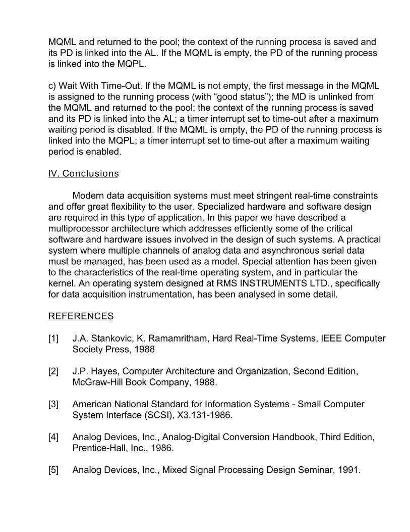
REFERENCES
[1] J.A. Stankovic, K. Ramamritham, Hard Real-Time Systems, IEEE ComputerSociety Press, 1988
[2] J.P. Hayes, Computer Architecture and Organization, Second Edition,McGraw-Hill Book Company, 1988.
[3] American National Standard for Information Systems - Small ComputerSystem Interface (SCSI), X3.131-1986.
[4] Analog Devices, Inc., Analog-Digital Conversion Handbook, Third Edition,Prentice-Hall, Inc., 1986.
[5] Analog Devices, Inc., Mixed Signal Processing Design Seminar, 1991.
[6] A.V. Oppenheim, R.W. Schafer, Digital Signal Processing, Prentice-Hall,Inc., 1985.
[7] H.M. Deitel, An Introduction to Operating Systems, Addison-Wesley, 1984.
[8] J.A. Stankovic, K. Ramamritham, “The design of the Spring kernel”,Proceedings of the Real-Time Syst. Symposium, Dec. 1987.
[9] Software Components Group, Inc., Passport+: A Technical Guidebook,1990.
[10] S.-C. Cheng, J.A. Stankovic, K. Ramamritham, “Scheduling algorithms forhard real-time systems - a brief survey”, in Hard Real-Time Systems, IEEEComputer Society Press, 1988.
FIG. I DATA ACQUISITION SYSTEM AND EXTERNAL EQUIPMENT

FIG. 2 MULTIPROCESSOR BASED ARCHITECTURE FORDATA ACQUISITION
FIG. 3 DATA FLOW IN DIGITAL (SERIAL) MODULE

FIG. 4 BASIC STRUCTURE OF THE REAL-TIME OPERATING SYSTEM
FIG. 5 BASIC STRUCTURE OF THE REAL-TIME KERNEL
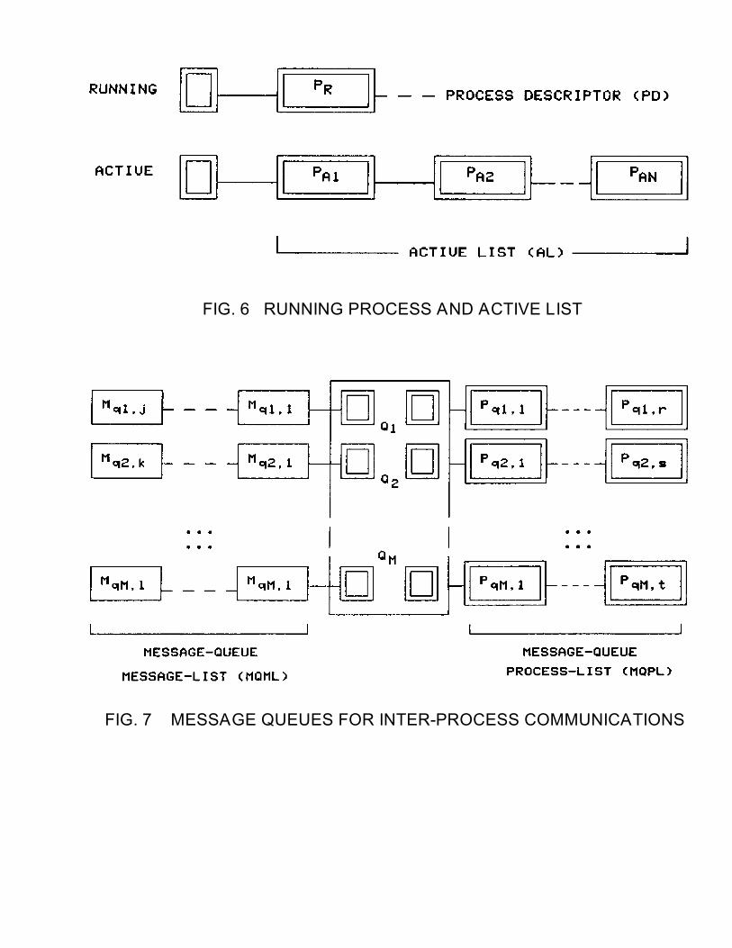
FIG. 6 RUNNING PROCESS AND ACTIVE LIST
FIG. 7 MESSAGE QUEUES FOR INTER-PROCESS COMMUNICATIONS