Multipole method for microstructured optical fibers. II. Implementation and results
10
Multipole method for microstructured optical fibers. II. Implementation and results Boris T. Kuhlmey Institut Fresnel (Unite ´ Mixte de Recherche du Centre National de la Recherche Scientifique 6133), Faculte ´ des Sciences et Techniques de Saint Je ´ro ˆ me, 13397 Marseille Cedex 20, France, and School of Physics, University of Sydney, Sydney, New South Wales 2006, Australia Thomas P. White School of Physics, University of Sydney, Sydney, New South Wales 2006, Australia Gilles Renversez and Daniel Maystre Institut Fresnel (Unite ´ Mixte de Recherche du Centre National de la Recherche Scientifique 6133), Faculte ´ des Sciences et Techniques de Saint Je ´ro ˆ me, 13397 Marseille Cedex 20, France Lindsay C. Botten School of Mathematical Sciences, University of Technology, Sydney, New South Wales2008, Australia C. Martijn de Sterke School of Physics, University of Sydney, Sydney, New South Wales 2006, Australia Ross C. McPhedran School of Physics, University of Sydney, Sydney, New South Wales 2006, Australia Received October 4, 2001; revised manuscript received May 7, 2002 We describe the numerical verifications of a multipole formulation for calculating the electromagnetic proper- ties of the modes that propagate in microstructured optical fibers. We illustrate the application of this for- mulation to calculating both the real and the imaginary parts of the propagation constant. We compare its predictions with the results of recent measurements of a low-loss microstructured fiber and investigate the variations in fiber dispersion with geometrical parameters. We also show that the formulation obeys appro- priate symmetry rules and that these rules may be used to improve computational speed. © 2002 Optical Society of America OCIS codes: 060.2280, 060.2400, 060.4510. 1. INTRODUCTION In a previous paper, hereafter referred to as Part I, 1 we described the development of a multipole formulation for calculating the propagation and field characteristics of microstructured optical fibers (MOFs). Here we discuss numerical aspects of the formulation, the choice of its pa- rameters to guarantee accurate results, and its numerical verification. The last is achieved through internal con- sistency tests and through a comparison both with other methods 2 and with recent experimental results obtained with a low-loss MOF structure. 3 We also present nu- merical results that illustrate important features of MOFs, such as the variation of the geometric loss of the modes that propagate in them and of their dispersion characteristics with MOF parameters. The numerical results given here and in Part I illustrate some key fea- tures of the formulation: incorporation of mode symme- try to answer definitively questions related to modal de- generacy, accurate and sensitive characterization of the geometric loss of modes, ability to deliver other modal data such as dispersion and field profiles, and modest computational requirements. The description of numerical strategies here is of neces- sity detailed, because the location of modes requires the finding of an approximate zero of the determinant of a large complex matrix. Such zeros are often difficult to distinguish at first sight from false minima, and it is nec- essary to employ various validation criteria for the modes that correspond to the various putative zeros to identify physically meaningful solutions. It is of course valuable to have numerical or experimental values for similar sys- tems to guide the mode search, and the curves and tables that we provide here and in Part I should provide a com- prehensive aid to workers in the future. Kuhlmey et al. Vol. 19, No. 10/October 2002/J. Opt. Soc. Am. B 2331 0740-3224/2002/102331-10$15.00 © 2002 Optical Society of America
Transcript of Multipole method for microstructured optical fibers. II. Implementation and results

Kuhlmey et al. Vol. 19, No. 10 /October 2002 /J. Opt. Soc. Am. B 2331
Multipole method for microstructured opticalfibers. II. Implementation and results
Boris T. Kuhlmey
Institut Fresnel (Unite Mixte de Recherche du Centre National de la Recherche Scientifique 6133),Faculte des Sciences et Techniques de Saint Jerome, 13397 Marseille Cedex 20, France, and School of Physics,
University of Sydney, Sydney, New South Wales 2006, Australia
Thomas P. White
School of Physics, University of Sydney, Sydney, New South Wales 2006, Australia
Gilles Renversez and Daniel Maystre
Institut Fresnel (Unite Mixte de Recherche du Centre National de la Recherche Scientifique 6133),Faculte des Sciences et Techniques de Saint Jerome, 13397 Marseille Cedex 20, France
Lindsay C. Botten
School of Mathematical Sciences, University of Technology, Sydney, New South Wales 2008, Australia
C. Martijn de Sterke
School of Physics, University of Sydney, Sydney, New South Wales 2006, Australia
Ross C. McPhedran
School of Physics, University of Sydney, Sydney, New South Wales 2006, Australia
Received October 4, 2001; revised manuscript received May 7, 2002
We describe the numerical verifications of a multipole formulation for calculating the electromagnetic proper-ties of the modes that propagate in microstructured optical fibers. We illustrate the application of this for-mulation to calculating both the real and the imaginary parts of the propagation constant. We compare itspredictions with the results of recent measurements of a low-loss microstructured fiber and investigate thevariations in fiber dispersion with geometrical parameters. We also show that the formulation obeys appro-priate symmetry rules and that these rules may be used to improve computational speed. © 2002 OpticalSociety of America
OCIS codes: 060.2280, 060.2400, 060.4510.
1. INTRODUCTIONIn a previous paper, hereafter referred to as Part I,1 wedescribed the development of a multipole formulation forcalculating the propagation and field characteristics ofmicrostructured optical fibers (MOFs). Here we discussnumerical aspects of the formulation, the choice of its pa-rameters to guarantee accurate results, and its numericalverification. The last is achieved through internal con-sistency tests and through a comparison both with othermethods2 and with recent experimental results obtainedwith a low-loss MOF structure.3 We also present nu-merical results that illustrate important features ofMOFs, such as the variation of the geometric loss of themodes that propagate in them and of their dispersioncharacteristics with MOF parameters. The numericalresults given here and in Part I illustrate some key fea-tures of the formulation: incorporation of mode symme-
0740-3224/2002/102331-10$15.00 ©
try to answer definitively questions related to modal de-generacy, accurate and sensitive characterization of thegeometric loss of modes, ability to deliver other modaldata such as dispersion and field profiles, and modestcomputational requirements.
The description of numerical strategies here is of neces-sity detailed, because the location of modes requires thefinding of an approximate zero of the determinant of alarge complex matrix. Such zeros are often difficult todistinguish at first sight from false minima, and it is nec-essary to employ various validation criteria for the modesthat correspond to the various putative zeros to identifyphysically meaningful solutions. It is of course valuableto have numerical or experimental values for similar sys-tems to guide the mode search, and the curves and tablesthat we provide here and in Part I should provide a com-prehensive aid to workers in the future.
2002 Optical Society of America

2332 J. Opt. Soc. Am. B/Vol. 19, No. 10 /October 2002 Kuhlmey et al.
2. VALIDATION AND SELF-CONSISTENCYThe formulation presented in Part I requires the findingof modes to satisfy a homogeneous equation or field iden-tity of the form
@I 2 R~H 1 J B0R0J 0B!#B [MB 5 0. (1)
This identity expresses the equality of two sets of fieldrepresentations: a local expansion in the neighborhoodof each cylindrical inclusion in the MOF,
Ez 5 (m52M
M
@AmElJm~k'
e rl! 1 BmElHm
~1 !~k'e rl!#exp~imu l!,
(2)
and a global, or Wijngaard, expansion,
Ez 5 (l51
Nc
(m
BmElHm
~1 !~k'e urlu!exp@im arg~r 2 cl!#
1 (m
AmE0Jm~k'
e r !exp~imu!. (3)
The Wijngaard expansion is expressed in local coordi-nates by use of Graf ’s addition theorem, truncated to thechosen multipole order M and equated with local expan-sion (2). The two expansions for Ez and the correspond-ing expansions for the scaled magnetic-field componentKz match perfectly only for untruncated fields (M → `),so their numerical difference on cylinder surfaces can beused as a powerful indicator of truncation errors and ofthe quality of the matrix null vector location. We illus-
trate this with an example, shown in Figs. 1 and 2, of anair-core MOF. Figure 1 shows significant field errors oc-curring near the boundary of the larger central air hole.As well, the low-frequency modulation of the field discrep-ancies indicates some imprecision in the minimization ofthe determinant. In Fig. 2 the multipole truncation or-der on the central hole has been increased to M 5 19,whereas the truncation order on the smaller holes hasbeen kept at 5. The decrease in field matching errors isevident (note the change in scale in between the bottompanels of Fig. 1 and those of Fig. 2) as is a slight improve-ment in the quality of the determinant minimization,manifested as a reduction in the low-frequency modula-tion. One clear sign of adequate convergence in the for-mulation is obtained from these comparison plots. Whenenough terms are included, the error term oscillates likethe first neglected term in field expansions $i.e., likeexp@i(M 1 1)u#%.
A second test of convergence is of course provided bythe stability of neff with respect to increase of M, as is il-lustrated in Table 1, where we also introduce
W 5
EC1
uEzlocal~u1! 2 Ez
Wijngaard~u1!udu1
EC1
uEzWijngaard~u1!udu1
. (4)
W is a measure of the accuracy of the equality betweenthe local [Eq. (2)] and the Wijngaard [Eq. (3)] expansions.With increasing M, W decreases and neff stabilizes, as ex-pected.
Fig. 1. Top, internal and bottom, Wijngaard expansions compared for R(Ez) and I(Ez) , respectively, for an air core MOF, with M5 5 for both the central air hole and all other air holes (3 rings; 54 air holes of diameter 4.0271 mm; core hole diameter, 13.0714 mm;
jacket diameter, 50 mm; ne 5 1.39; ni 5 1.00; n0 5 1.39 1 1028i; L 5 5.78157 mm; l 5 3.846 mm).

Kuhlmey et al. Vol. 19, No. 10 /October 2002 /J. Opt. Soc. Am. B 2333
Fig. 2. As for Fig. 1 but with M 5 19 for the core hole and M 5 5 for all other holes. Note that the Wijngaard and internal expansionsnow match with graphic accuracy.
We have found that the choice of truncation parameterM should be made such that this quantity clearly exceeds(by a factor of ;1.5) the largest argument of Bessel func-tions on the boundary of inclusions. This choice of Mguarantees that the cylindrical functions of largest orderin field expansions behave as cylindrical multipoles ofelectrostatics to leading order [i.e., as rn exp(imu) andr2n exp(imu)] and ensures rapid convergence with in-creasing m. This criterion is manifest in Figs. 1 and 2,where many more Bessel terms are necessary for thelarge central hole than for other, smaller holes.
A powerful way to validate a new formulation is to com-pare its results with those of a well-established method.A comparison has already been made2 of the results of ourmethod with those of the scalar and vector beam propa-gation methods, for a MOF fiber that has a single ring of
Table 1. Convergence of neff with Ma
M R(neff) I(neff) 3 106 W
3 1.43852886240663 6.918242988502046 9.7 3 1022
4 1.43838719374803 1.749096334333127 4.6 3 1022
5 1.43836672605884 1.373925319699950 1.5 3 1022
6 1.43836499998690 1.414928166193201 2.7 3 1023
7 1.43836493475660 1.416468499483090 9.3 3 1024
8 1.43836493461317 1.416459892560528 7.7 3 1024
9 1.43836493424529 1.416475747100788 2.5 3 1024
a Results are for the p 5 1 mode of the MOF in Table 1 of Part I atl 5 1.45 mm. Here W from Eq. (4) gives the degree of accuracy of theequality between Wijngaard and local expansions. The integrals aretaken over the boundary of cylinder 1 situated at r 5 6.75 mm, u 5 0.
inclusions, and with the imaginary part of neff 5 b/k0 oforder 1025. We note that we have successfully used ourformulation to study the effects of increasing the numberof rings of inclusions, pushing the imaginary part of neffdown to ;10211 by direct means before losing accuracy inits determination. In Section 5 we discuss an indirectmethod, which is capable of reaching lower values of theimaginary part.
As we also included in our software the extension of thepresent formalism to simulate the diffraction of incidentlight by the structure, we were able to validate the codethoroughly against results from other, well-establisheddiffraction codes. Comparisons with a fictitious sourcecode4 and with other multipolelike codes5,6 in conical in-cidence with complex or real permittivities in various ge-ometries gave excellent agreement, to at least eight deci-mal places, for the radar cross section, validating eachpart of the code separately as well as in its entirety.
3. SYMMETRYThe incorporation of field symmetry into the multipoleformulation has two benefits: First, it enables definitivestatements to be made about the degeneracy of modes,even in the presence of the accidental degeneracies thatarise when normally distinct modal trajectories crosseach other. Second, it greatly reduces computationalburdens, enabling accurate answers for quite large MOFstructures to be obtained rapidly on personal computers(PCs).
In applying the multipole formulation to large sixfoldsymmetric MOFs it is highly advantageous to exploit the
2334 J. Opt. Soc. Am. B/Vol. 19, No. 10 /October 2002 Kuhlmey et al.
symmetry properties in Fig. 3 of Part I to reduce the sizeof matrixM. This can be achieved because only multi-pole coefficients for inclusions lying in the minimum sec-tor indicated in Fig. 3 of Part I need be specified; those forholes outside the minimum sector can be obtained by mul-tiplying by the appropriate geometric phase factor [re-lated to exp(2pi/6)]. The resultant reduction in the orderof matrix M depends on the type of mode that is ad-dressed; it is maximal for the nondegenerate modes inFig. 3 of Part I and is ;3.5 for degenerate modes, leadingto considerable reductions in processing time. See Ap-pendix A for further details.
4. IMPLEMENTATIONHere we discuss the implementation of our method to findmodes and dispersion characteristics of a given fiberstructure.
A. Finding ModesFor the task of finding modes we need an algorithm aimedat finding all the zeros of the determinant ofM in a re-gion of the complex neff plane. The algorithm should beeconomical in function calls, as each evaluation of the de-terminant is computationally expensive for large struc-tures. As shown in Fig. 2 of Part I, the zeros are sharp,so a highly accurate first estimate of the zero is necessaryfor most simple root-finding routines. More-specific algo-rithms for finding zeros of analytic or meromorphicfunctions7,8 have good convergence for simple structures(with six cylinders, for example) but fail for more-complexstructures, even with good initial guesses. Our presentapproach to root finding seems computationally efficient.We first compute a map of the modulus of the determi-nant over the region of interest and then use the localminima of this map as initial points for a mixed zoomingand modified Broyden9 algorithm (an iterative minimiza-tion algorithm, guaranteed to converge for parabolicminima). Further details of this method are given in Ap-pendix B.
The initial scanning region has to be chosen in accor-dance with the physical problem studied: If the fiber isair cored, and air guided modes are sought, we chooseR(neff) , 1, whereas if the fiber has a solid core we usu-ally choose to search for modes in a region where R(neff)lies between the optical indices of the inclusions and thematrix. In the latter case hundreds of modes may existfor small R(neff), which are of little interest because oftheir high losses. We therefore often concentrate on asmaller neff scanning region near the highest index of thestructure. A scanning region for I(neff) that gives goodresults in almost any case is 10212 , I(neff) , 1023.
B. Dispersion CharacteristicsThe process of finding modes as described above is carriedout for a specific wavelength. We could repeat the searchfor modes for many different wavelengths to obtain dis-persion characteristics, but this process would be quite la-borious. We have found two other methods to be of value.One computes and identifies the modes for three or fourdifferent wavelengths, then uses a spline interpolation toestimate the neff values for other wavelengths, and refines
the estimate with the mixed zooming and Broyden algo-rithm. Each newly determined point of the neff(l) curvecan be used to enhance the spline estimate. The second(and often more efficient) method is to compute the modesfor only one wavelength, l0 , then slightly perturb thewavelength to get neff(l0 1 dl), with neff(l0) used as a firstguess, and then use a first-order estimate of neff at thenext wavelength. One can then compute neff(l 1 mdl),using a first-order estimate computed from the two pre-ceding values. For both methods the wavelength stephas to be chosen very small: For small steps more pointsare necessary for computing the dispersion characteris-tics in a given wavelength range, but for large steps thefirst-order guess becomes inaccurate and the convergenceof the zooming and Broyden algorithm unacceptably slow.Having small steps and therefore numerous numericalvalues on the dispersion curve is also of benefit when oneis evaluating second-order derivatives, as is necessary tocompute the group-velocity dispersion.
One can include material dispersion easily by changingthe optical indices according to the current wavelength ateach step, using, for example, a Sellmeier approxima-tion10 for silica.
The method described here can be adapted to a study ofthe change of neff of a mode for any continuously varyingparameter, for example, cylinder radius, cylinder spacing,and optical index. One problem that can occur when oneis following the evolution of a mode with a continuouslyvarying parameter is mode crossing. Mode crossing re-sults in wrong data but can easily be detected in mostcases through a discontinuity of derivatives and can alsoeasily be eliminated by restarting of the algorithm withthe correct mode on the other side of the crossing.
The correct choice for dl strongly depends on wave-length and structure, so no general advice can be given.However, as a rough guide, satisfactory results have gen-erally required ;1000 points per unit l/L on curves.
C. Using the Symmetry SimplificationsWhen the structure of interest presents symmetries,these can be used as described in Ref. 11 to improve thecomputations considerably, as mentioned in Subsection3.B of Part I and detailed in Appendix A. The search formodes changes slightly in this case.
To obtain all the modes we now have to check for eachclass of mode separately. This entails going through theentire process of evaluating a determinant map and refin-ing each local minimum once per nondegenerate modeclass and once for each degenerate pair of mode classes.For a structure with C6v symmetry, six determinant mapshave to be evaluated [classes 1–3, 5, 7 and 8; the modes ofclasses 4 and 6 are deduced from those of classes 3 and 5(cf. Fig. 3 of Part I)]. But, as the matrix size is reducedby a factor ranging from 3.5 to more than 6, and the com-putations scale as the size of the matrix cubed, the overallefficiency gain of using the symmetries remains high.The gain is even higher when dispersion figures are com-puted for a given mode, as only one symmetry class isthen concerned.
D. Software and Computational DemandsWe have developed a FORTRAN 90 code to exploit the con-siderations detailed above. For symmetric structures the

Kuhlmey et al. Vol. 19, No. 10 /October 2002 /J. Opt. Soc. Am. B 2335
suggested optimizations are used and the software cantherefore deal, even on PCs, with large structures (modesfor fibers with 180 holes have so far been computed oncurrent PCs). Once the structure has been defined, thesoftware is able to find automatically all the modes withina given region of the complex plane for neff and can op-tionally track a mode as a function of wavelength to ob-tain dispersion characteristics. Material dispersion canbe included, if desired.
Computational demands are relatively modest: Thecomplete set of modes with M 5 5 in the region of inter-est, 1.4 , R(neff) , 1.45 for the structure used in Figs. 2and 4–6 of Part I, can be computed on a Pentium III (733-MHz) PC in less than 3 min, using less than 2 Mb ofmemory. Of course the load rises for larger structures,but the complete set of modes for a structure of three lay-ers of holes in a hexagonal arrangement as used in Sub-section 5.B of this paper takes less than 1 h (and ;15 Mbof memory) on a Compaq workstation. Dispersion curvescan be computationally more expensive: The loss curvesin Subsection 5.B took ;0.5 h (for d/L 5 0.075, where weused M 5 5) to several hours (for d/L 5 0.7, whereM 5 7 was needed for accuracy).
5. FIBER GEOMETRY AND MODEPROPERTIESA. Dispersion in Microstructured Optical FibersOne of the important features of MOFs is the powerfulcontrol that their geometry exerts over the dispersioncharacteristics of modes.12 In a standard single-mode fi-ber, the total dispersion consists of material and wave-
guide contributions, whose combination is normal in thenear infrared for wavelengths up to lzc . 1.31 mm and isanomalous beyond that.10 Dispersion-shifted fibers canshift the zero-dispersion point to longer wavelengths,whereas dispersion can be reduced over a range of wave-lengths by other designs.
In Fig. 3 we show the evolution of key dispersion pa-rameters with both wavelength and hole radius for asolid-core MOF with three rings of holes, for which the in-dex of silica is modeled by the Sellmeier equation. Theparameters displayed are R(neff), I(neff), vg /c, and D,where
vg 5 cS neff 1 vdneff
dvD 21
(5)
is the group velocity10 and
D 5 2l
c
d2R~neff!
dl2 (6)
is the dispersion parameter. Noticeable trends in thefour quantities are the steady decrease in R(neff) as thehole size increases, the decrease in the loss or I(neff) withincreasing hole size and better confinement; the steadyincrease in group velocity with increasing air fraction;and the movement of lzc with hole diameter, initiallyabove the step-index fiber value and then back downthrough it and sweeping toward the visible as d/L in-creases further. This ability to vary the zero-dispersionpoint by a wavelength factor that approaches 2 offers ex-citing possibilities for fiber designs.12
Fig. 3. Dispersion as a function of wavelength for solid-core MOFs in silica with three rings of holes for various values of d/L, withL 5 2.3 mm, n0 5 nsilica , and the Sellmeier model for dispersion of silica.
2336 J. Opt. Soc. Am. B/Vol. 19, No. 10 /October 2002 Kuhlmey et al.
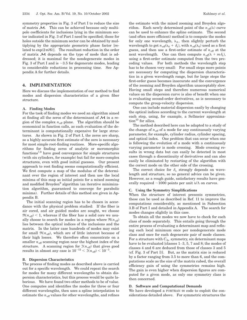
B. Confinement LossesAs modes in MOFs are not strictly confined but lossy, it isimportant to be able to evaluate the confinement lossesthat are intrinsically related to the MOF geometry. Westudied the case of a silica MOF perforated with cylindri-cal air holes whose centers are arranged hexagonally andcomputed the loss figures for the first few modes at awavelength of 1.55 mm, varying pitch, diameter-to-pitchratio, and number of rings. In this study the jacket wastaken to be made from silica.
Figure 4 shows the loss values for the fundamentalmode of a solid-core MOF with three rings of holes withvarious pitches for different diameter-to-pitch ratios. Itis clear that guidance becomes better for bigger holes, andour simulations show that larger pitches are favorable forlower losses. This can be explained phenomenologicallyas follows: The real part of the effective index of the fun-damental mode tends to the refractive index of silica, sothe propagation becomes increasingly parallel to the fiberaxis. Interaction with the confining structure is thusminimized.
This behavior is also found for nonfundamental modes.Figure 5 shows the loss values with various pitches forthe first three modes of a MOF with three rings of holes,for a diameter-to-pitch ratio of d/L 5 0.4. Note thatnonfundamental modes always exist, even for structuresclaimed to be single mode, but can be much more lossy
Fig. 4. Confinement loss figures for the fundamental mode of aMOF with three rings of air holes of various diameters andpitches. All curves are for l 5 1.55 mm.
Fig. 5. Confinement loss figures for the first three modes of aMOF with three rings of air holes as a function of pitch. Hered/L 5 0.4, l 5 1.55 mm.
than the fundamental mode. As losses vary continuallywith parameters and no truly bound modes exist in thecase of MOFs, the definition of a single-mode MOF can beonly relative. Moreover, it emerges from our numericalresults that introducing an air jacket about the MOFmakes these three modes truly bound @I(neff) 5 0#, whileothers remain leaky. This phenomenon shows the impor-tance of the jacket and is currently under investigation.
Data showing confinement loss as a function of thenumber of rings and their diameter-to-pitch ratio, withL 5 2.3 mm, for a wavelength l 5 1.55 mm, have al-ready been reported.13 Depending on the value of d/L,as many as eight rings of holes were necessary to reduceconfinement loss below 1 dB/m.
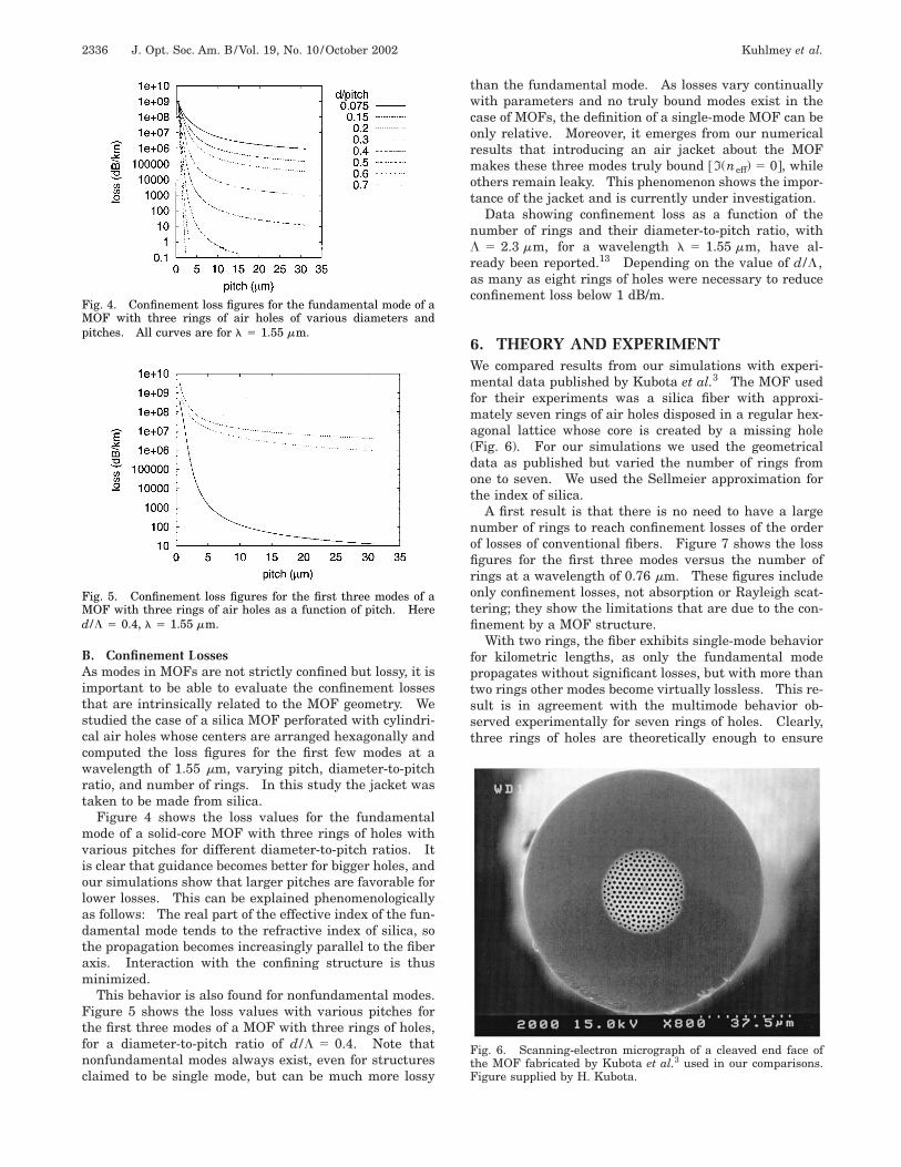
6. THEORY AND EXPERIMENTWe compared results from our simulations with experi-mental data published by Kubota et al.3 The MOF usedfor their experiments was a silica fiber with approxi-mately seven rings of air holes disposed in a regular hex-agonal lattice whose core is created by a missing hole(Fig. 6). For our simulations we used the geometricaldata as published but varied the number of rings fromone to seven. We used the Sellmeier approximation forthe index of silica.
A first result is that there is no need to have a largenumber of rings to reach confinement losses of the orderof losses of conventional fibers. Figure 7 shows the lossfigures for the first three modes versus the number ofrings at a wavelength of 0.76 mm. These figures includeonly confinement losses, not absorption or Rayleigh scat-tering; they show the limitations that are due to the con-finement by a MOF structure.
With two rings, the fiber exhibits single-mode behaviorfor kilometric lengths, as only the fundamental modepropagates without significant losses, but with more thantwo rings other modes become virtually lossless. This re-sult is in agreement with the multimode behavior ob-served experimentally for seven rings of holes. Clearly,three rings of holes are theoretically enough to ensure
Fig. 6. Scanning-electron micrograph of a cleaved end face ofthe MOF fabricated by Kubota et al.3 used in our comparisons.Figure supplied by H. Kubota.

Kuhlmey et al. Vol. 19, No. 10 /October 2002 /J. Opt. Soc. Am. B 2337
guidance that is limited only by losses caused by absorp-tion or structural imperfections. We confirm that thelosses observed by Kubota et al. (7.1 dB/km at 850 nm)are due not to the limitation imposed by the MOF geom-etry of the fiber but mainly to Rayleigh scattering, struc-tural imperfections, or absorption.
The imaginary parts of neff that correspond to Fig. 7 arewell below those that can be determined directly by deter-minant minimization. Instead we must proceed throughthe evaluation of I(neff) by an energy flux argument, oncethe real part of neff has been determined to high accuracyby determinant minimization. Loss coefficient a is ob-tained through the conservation of the time-averaged fluxof Poynting vector S through a cylinder of elementarylength dz centered at the origin and with a radius R suchthat the cylinder includes all inclusions. We have
EEu,r,R
R@S~r, u, z !# • uzrdrdu
5 dz RuR@S~R, u, z !# • urRdu
1 EEu,r,R
R@S~r, u, z 1 dz !# • uzrdrdu, (7)
where uz and ur are the usual unit vectors of the local ba-sis in cylindrical coordinates. As S varies as e2az, wehave
S~r, u, z 1 dz ! . ~1 2 adz !S~r, u, z !, (8)
so Eq. (7) becomes
aEEr,R,u
R@S~r, u, z !# • uzrdrdu
5 RuR@S~R, u, z !# • urRdu. (9)
Isolating a gives
a 5
RuR@Sr~R, u, z !#Rdu
EEu,r,R
R@Sz~r, u, z !#rdrdu
, (10)
Fig. 7. Loss of the first three modes as a function of number ofrings for the structure published by Kubota et al.,3 at a wave-length of 0.76 mm. Only confinement losses are included.
where we have introduced Sz and Sr , components of S incylindrical coordinates. The imaginary part of the effec-tive index is then given by
I~neff! 5a
2k0. (11)
We computed dispersion figures for the fundamentalmode of the Kubota structure. We first observed that, forthis structure, the number of rings has little influence onthe actual dispersion curve, as the fundamental mode isalready well confined with one ring. We therefore used aone-ring structure in subsequent simulations to improvecomputational speed without losing significant accuracyfor dispersion parameters. Although we observed a shiftof the zero-dispersion wavelength to the 800-nm band, wedid not find exact agreement with the experimental zero-dispersion wavelength of 810 nm. With the given geo-metrical data we found a zero-dispersion wavelength of889 nm. Kubota et al. found similar results with a finite-difference time-domain method. To explain the differ-ence from experimental data we computed the zero-dispersion wavelength for various hole pitches anddiameters: In Fig. 8, pitch is varied and diameter is heldconstant; in Fig. 9, diameter is varied and pitch is heldconstants; in Fig. 10, pitch and diameter are both varied
Fig. 8. Zero-dispersion wavelength as a function of pitch for thestructure published by Kubota et al.,3 with constant diameterd 5 1.51 mm.
Fig. 9. Zero-dispersion wavelength as a function of hole diam-eter for the structure published by Kubota et al.,3 with constantpitch L 5 2.26 mm.

2338 J. Opt. Soc. Am. B/Vol. 19, No. 10 /October 2002 Kuhlmey et al.
and the pitch/diameter ratio is held constant. These fig-ures show that a variation of ;15% in pitch with a con-stant diameter or of 25% in pitch with a constantdiameter/pitch ratio is necessary to produce the experi-mental zero dispersion wavelength.
7. CONCLUSIONSThe accuracy and computational speed of the multipoleformulation described above offer important advantagesfor understanding or exploiting the properties of MOF fi-bers. The results presented show clearly the details offield structures and symmetry properties. The formula-tion is at present limited to designs composed of noninter-secting circular inclusions; nevertheless, it can be em-ployed in studies ranging over a wide parameter space:hole radius, spacing, number of rings, packing geometry,air or solid core, etc. As we saw, the strong index con-trast between air and silica means that fiber parameterscan be tuned across a wide range as these parametersvary, so MOF fibers may well offer a new generation of fi-ber devices with novel properties. Multipole formula-tions will be a valuable tool in the quest to develop thesedevices.
One interesting issue that merits further investigationwas raised in Section 5. The structure formulated byKubota et al.3 was shown to be single moded for two ringsof air holes and multimoded for kilometric lengths withthree or more rings. The identification of the number ofmodes that are physically significant at a particularwavelength depends on the fiber length in question,which dictates the upper limit on mode loss, which is onefactor in deciding how many modes can compete to carryenergy from one end of the fiber to the other. As we haveseen, mode loss varies strongly with mode number, holespacing and size, and number of rings of holes. Thus acomprehensive numerical study will be necessary to pro-vide data on mode loss as a function of these parametersfrom which a useful definition of mode number in MOFsmay emerge.
Finally, we add a few remarks that place our multipolemethod in the context of the range of competing tech-niques for numerically studying MOF’s. First, as wehave shown, the multipole method is capable of yieldingthe geometric loss of finite MOF confining structures,with I(neff) accessible to 10214 or lower. This is a prop-
Fig. 10. Zero-dispersion wavelength as a function of pitch forthe structure published by Kubota et al.,3 with constantdiameter/pitch ratio d/L 5 0.67.
erty that is not likely to be emulated easily by other meth-ods and is certainly unique at this time. Second, themethod has been constructed in such a way that symme-try properties of modes can be enforced within the formu-lation, so questions of degeneracy are exactly answered.Third, it delivers highly accurate data on propagationconstants and field patterns for modes by using quitemodest computing resources if the MOF contains a rea-sonable number of air holes. There are drawbacks to themethod, of course: It is at present restricted to circularair holes, and mode searching for an unfamiliar geometrymay be difficult and time consuming. Nevertheless, themultipole formulation is likely to prove highly valuable incoming years, as designers move to exploit the manifoldpossibilities afforded by a new generation of optical fibers.
APPENDIX A: SYMMETRIZATION OFMODESWe consider waveguides with C6v symmetry, such as thestructures in Fig. 6. As was shown by McIsaac,14 suchstructures have eight mode classes, four of which occur astwo degenerate pairs, as shown in Fig. 3 of Part I. Forthe purpose of this example we are interested in the de-generate fundamental modes p 5 3 and p 5 4 and in thelowest-order nondegenerate modes p 5 1 and p 5 2.The minimum waveguide segments illustrated in Fig. 3 ofPart I represent the smallest segment of fiber required forfully defining the modal fields of the complete structure.We relate the multipole coefficients for a secondary cylin-der outside the minimum segment to those of the corre-sponding primary cylinder inside the segment.
From Fig. 3 of Part I, nondegenerate mode classes 1and 2 have minimum waveguide segments of p/6, so 3 pri-mary cylinders are required for describing the 18-holestructure shown in Fig. 11. The holes are labeled PS ,where P is the primary cylinder and S is the label given tothe secondary cylinder. Hole 11 is primary cylinder 1and lies in the inner shell; the other primary cylinders, 21and 31 , lie in the second shell. As they are not degener-ate, these modes must exhibit the full sixfold symmetry ofthe structure.
Fig. 11. Primary (bold circles) and secondary cylinders of thenondegenerate p 5 1 and p 5 2 mode classes of a two-ring MOFstructure.
Kuhlmey et al. Vol. 19, No. 10 /October 2002 /J. Opt. Soc. Am. B 2339
In terms of the multipole coefficients of the electric fieldbm
E , the relation between those on secondary cylinders tothose on primary cylinders can be expressed in the form
bmE~PS!
5 bmE~P1! exp@im~S 2 1 !p/3#,
and similarly for the magnetic-field coefficients.For degenerate mode classes 3 and 4, the number of
secondary cylinders that correspond to a given primarycylinder depends on the position of the primary cylinder.If the primary cylinder lies on a symmetry axis of themode, in this case either the x or the y axis, then only oneother cylinder is related to it. A primary cylinder that isnot on a symmetry axis has three associated secondarycylinders. A cylinder positioned at the center of thestructure has no secondary cylinders. The related pri-mary and secondary cylinders are shown in Fig. 12.
For classes 3 and 4 the fields are either symmetric orantisymmetric about the transverse axes. The relationbetween primary and secondary cylinders is obtained byappropriate combinations of reflections and inversions togive the correct symmetry properties.
For mode p 5 3 the multipole coefficients on a second-ary cylinder lying on the x axis are related to those on thecorresponding primary cylinder by a simple reflection ofEz and antireflection of Kz across the y axis:
bmE~P2!
5 2b2mE~P1! , bm
K~P2!5 b
2mK~P1! .
Similarly, for a secondary cylinder on the y axis the re-lations are
bmE~P2!
5 ~21 !mb2mE~P1! , bm
K~P2!5 ~21 !m11b
2mK~P1! .
As mentioned above, a primary cylinder that does notlie on either axis has three associated secondary cylin-ders. The relations are again combinations of reflectionsand antireflections about the axes:
bmE~P2!
5 2b2mE~P1! , bm
K~P2!5 b
2mK~P1! ,
bmE~P3!
5 ~21 !m11bmE~P1! , bm
K~P3!5 ~21 !m11bm
K~P1! ,
bmE~P4!
5 ~21 !mb2mE~P1! , bm
K~P4!5 ~21 !m11b
2mK~P1! .
Fig. 12. Primary (bold circles) and secondary cylinders of thedegenerate p 5 3 and p 5 4 mode classes of a two-ring MOFstructure.
We obtain the relations for the second degenerate modeclass p 5 4 simply by swapping the bm
E and bmK coeffi-
cients in the equations above.These symmetry relations are used in our method to re-
express field identity (1) in terms of the primary cylindersonly. This reduces the matrix dimensions by a factor of3.5–6, depending on the mode class, thus greatly increas-ing the calculation speed and allowing larger structuresto be studied.
APPENDIX B: ALGORITHMWe compute the determinant for a number of points0 < ir < Nr over 0 < ii < Ni lines parallel to the realaxis, with imaginary parts varying exponentially with ii .The exponential variation of the imaginary part is neces-sary, as different modes can have losses that differ by sev-eral orders of magnitude. Local minima of this array arecomputed through simple data analysis, and better initialguesses of the minima are estimated through interpola-tion of the points adjacent to each minimum. This guessis used as a starting point for a Broyden-like algorithm.If the algorithm fails, a new map of the determinant iscomputed over the region in which the first mappingshowed that there is a local minimum. This refinementmap uses a region of 5 3 5 points, with a linear scale forboth real and imaginary parts. If the only minima of therefined region are on its border, the region is extended un-til a minimum lies inside the region. During the enlarge-ment of the region, care is taken to prevent regions fromoverlapping regions in which computing errors can occur(negative or excessive imaginary or real part). If a mini-mum is found in the refined region (excluding the bor-ders), the routine tries the Broyden-like algorithm again.If multiple minima are found in the region, each mini-mum is added to the initial minima list and is treatedseparately: Missing a zero thus becomes highly unlikely.During the Broyden algorithm a calculation of singularvalues is performed (see Subsection 3.A of Part I) eachtime the modulus of the determinant for the current pointis less than a parameterized threshold, and we analyzethe modules of the eigenvalues to determine whether anacceptable solution has been found (see the discussion inSubsection 3.A of Part I).
The routine continues to alternate Broyden and zoom-ing algorithms until one of the following occurs:
• An acceptable solution is found,• The extended mapping region concentrates near a
border of the initial region,• The refined region becomes too small,• The extended mapping region includes a minimum
of the initial determinant map that has already beentreated, or
• A maximum number of iterations is reached.
Depending on the width of the initial scanning regionand the complexity of the structure, the pertinent choiceof Nr varies from ;50 to several hundreds: Structureswith a substantial number of cylinders have a higher den-sity of modes and therefore need a better resolution onthe initial determinant map. The value of Ni , even forintricate structures, does not need to be high and is usu-

2340 J. Opt. Soc. Am. B/Vol. 19, No. 10 /October 2002 Kuhlmey et al.
ally taken from 4 to 8. As shown in Fig. 2 of Part I, zerosare usually associated with valleys parallel to the imagi-nary axis, so precise maps parallel to the real axis for afew values of the imaginary part are sufficient for findinga first estimate of the zeros.
ACKNOWLEDGMENTSThis study was supported by the Australian ResearchCouncil. It has benefitted from travel support providedby the French and Australian governments. H. Kubotais thanked for discussion of experimental results and pro-vision of figures.
R. C. McPhedran’s e-mail address is [email protected].
REFERENCES1. T. P. White, B. T. Kuhlmey, R. C. McPhedran, D. Maystre,
G. Renversez, C. M. de Sterke, and L. C. Botten, ‘‘Multipolemethod for microstructured optical fibers. I. Formula-tion,’’ J. Opt. Soc. Am. B 19, 2322–2330 (2002).
2. M. J. Steel, T. P. White, C. M. de Sterke, R. C. McPhedran,and L. C. Botten, ‘‘Symmetry and degeneracy in microstruc-tured optical fibers,’’ Opt. Lett. 26, 488–490 (2001).
3. H. Kubota, K. Suzuki, S. Kawanishi, M. Nakazawa, M.Tanaka, and M. Fujita, ‘‘Lowloss, 2-km-long photonic crys-tal fiber with zero GVD in the near IR suitable for picosec-ond pulse propagation at the 800 nm band,’’ in Conference
on Lasers and Electro-Optics (CLEO2001), Vol. 56 of OSATrends in Optics and Photonics Series (Optical Society ofAmerica, Washington, D.C., 2001), paper C3.
4. F. Zolla and R. Petit, ‘‘Method of fictious sources as appliedto the electromagnetic diffraction of a plane wave by a grat-ing in conical mounts,’’ J. Opt. Soc. Am. A 13, 1087–1096(1996).
5. D. Felbacq, G. Tayeb, and D. Maystre, ‘‘Scattering by a ran-dom set of parallel cylinders,’’ J. Opt. Soc. Am. A 11, 2526–2538 (1994).
6. E. Centeno and D. Felbacq, ‘‘Rigorous vector diffraction ofelectromagnetic waves by bidimensional photonic crystals,’’J. Opt. Soc. Am. A 17, 320–327 (2000).
7. P. Kravanja and M. Van Barel, Computing the Zeros of Ana-lytic Functions (Springer-Verlag, Berlin, 2000).
8. L. C. Botten, M. S. Craig, and R. C. McPhedran, ‘‘Complexzeros of analytic functions,’’ Comput. Phys. Commun. 29,245–259 (1983).
9. C. G. Broyden, ‘‘A class of methods for solving nonlinear si-multaneous equations,’’ Math. Comput. 19, 577–593 (1965).
10. G. P. Agrawal, Nonlinear Fiber Optics (Academic, San Di-ego, Calif., 1995).
11. E. Yamashita, S. Ozeki, and K. Atsuki, ‘‘Modal analysismethod for optical fibers with symmetrically distributedmultiple cores,’’ J. Lightwave Technol. 3, 341–346 (1985).
12. D. Mogilevtsev, T. A. Birks, and P. St. J. Russell, ‘‘Group-velocity dispersion in photonic crystal fibers,’’ Opt. Lett. 23,1662–1664 (1998).
13. T. P. White, R. C. McPhedran, C. M. de Sterke, and M. J.Steel, ‘‘Confinement losses in microstructured optical fi-bers,’’ Opt. Lett. 26, 488–490 (2001).
14. P. R. McIsaac, ‘‘Symmetry-induced modal characteristics ofuniform waveguides. I. Summary of results,’’ IEEETrans. Microwave Theory Tech. MTT-23, 421–429 (1975).


![Anthracene Fibers Grown in a Microstructured Optical Fiber ...€¦ · Many experimental techniques have been explored to grow and characterize anthracene crystals [21–24]. Large](https://static.fdocuments.in/doc/165x107/60052648d534fa307c57888b/anthracene-fibers-grown-in-a-microstructured-optical-fiber-many-experimental.jpg)