Multiplexing - Website Staff UIstaff.ui.ac.id/.../ir.muhammad/material/kuliah7-8multiplexing.pdf ·...
54
Slide 1 Muhamad Asvial 11.4.2006 http://www.ee.ui.ac.id/~cicer Multiplexing
Transcript of Multiplexing - Website Staff UIstaff.ui.ac.id/.../ir.muhammad/material/kuliah7-8multiplexing.pdf ·...
Slide 1Muhamad Asvial
11.4.2006http://www.ee.ui.ac.id/~cicer
Multiplexing
Slide 2Muhamad Asvial
11.4.2006http://www.ee.ui.ac.id/~cicer
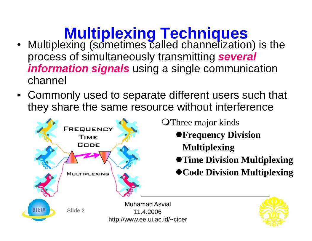
Multiplexing Techniques• Multiplexing (sometimes called channelization) is the
process of simultaneously transmitting several information signals using a single communication channel
• Commonly used to separate different users such that they share the same resource without interference
Three major kindsFrequency Division
MultiplexingTime Division MultiplexingCode Division Multiplexing

Slide 3Muhamad Asvial
11.4.2006http://www.ee.ui.ac.id/~cicer
Frequency Division Multiplexing (FDM)• In FDM, the available bandwidth is divided into non-overlapping frequency
slots• Each message is assigned a frequency slot within the available band• Signals are translated to different frequency band using modulation and then
added together to form a baseband signal• The signals are narrowband and frequency limited• FDM can be used for either digital or analog transmission
Frequency Band 1
Frequency Band 2
Frequency Band N
f0
f2
fN-2
fN-1
f1
f3
Time
Freq
uenc
y
Slide 4Muhamad Asvial
11.4.2006http://www.ee.ui.ac.id/~cicer
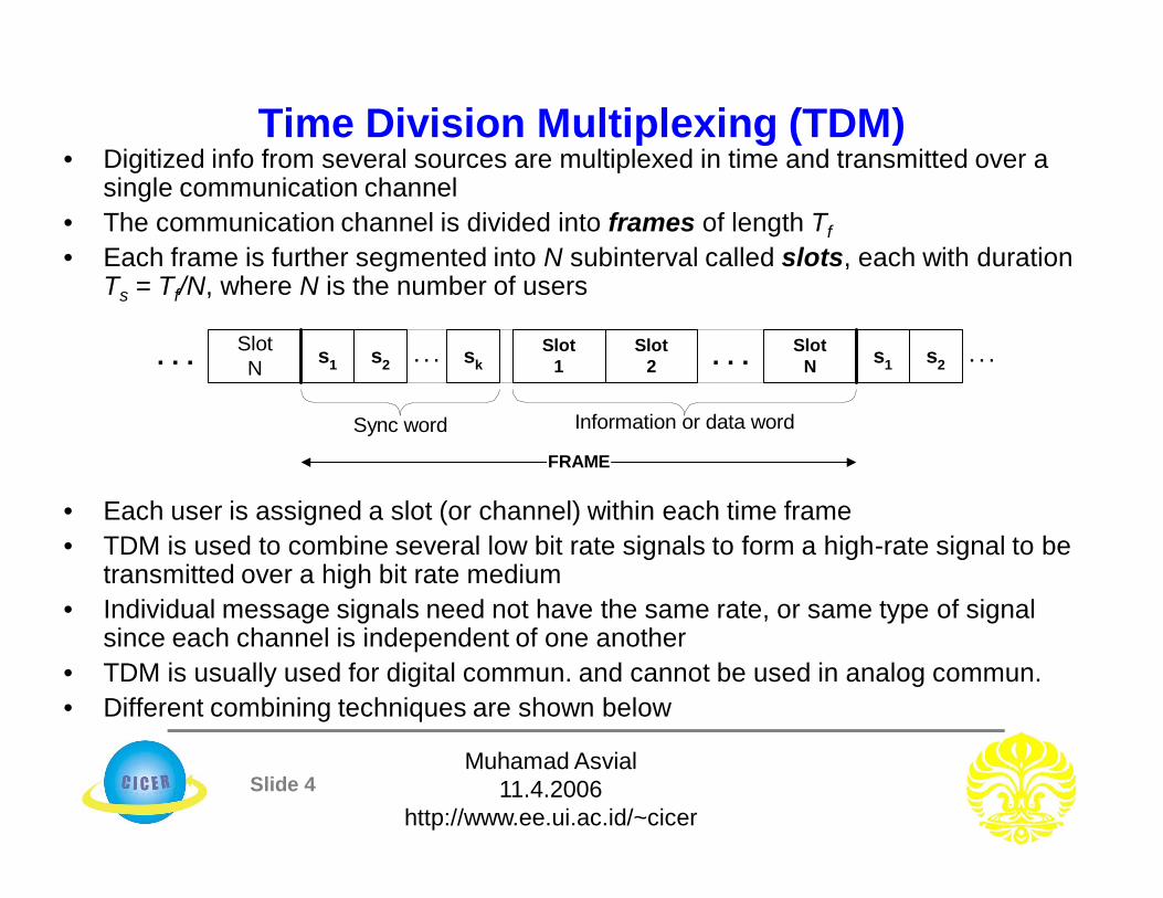
Time Division Multiplexing (TDM)• Digitized info from several sources are multiplexed in time and transmitted over a
single communication channel• The communication channel is divided into frames of length Tf• Each frame is further segmented into N subinterval called slots, each with duration
Ts = Tf/N, where N is the number of users
• Each user is assigned a slot (or channel) within each time frame• TDM is used to combine several low bit rate signals to form a high-rate signal to be
transmitted over a high bit rate medium• Individual message signals need not have the same rate, or same type of signal
since each channel is independent of one another• TDM is usually used for digital commun. and cannot be used in analog commun.• Different combining techniques are shown below
Slot1
Slot2
SlotNs1 s2 sk . . .
FRAME
. . .
Sync word Information or data word
s1 s2 . . .SlotN. . .

Slide 5Muhamad Asvial
11.4.2006http://www.ee.ui.ac.id/~cicer
Code Division Multiplexing• CDM is a multiplexing method where multiple users are permitted to transmit
simultaneously on the same time and same frequency• In CDM system, users time share a higher-rate digital channel by overlaying
a higher-rate digital sequence on their transmission• Each user is assigned distinct code sequence (or waveform)
• This technique may be viewed as a combination of FDM and TDM using some sort of code
Signal 1
Signal 3
Signal 2
...
...
Freq
uenc
y D
omai
n
Time Domain
Signal 2
Signal 1
Signal 3
...
Signal 1
Signal 3
Signal 2
...
...
...
Slot 1 Slot 2 Slot 3
Band 1
Band 2
Band 3
Code Division Multiplexing

Slide 6Muhamad Asvial
11.4.2006http://www.ee.ui.ac.id/~cicer
Wavelength Division Multiplexing (WDM)• In optics, the process of using laser source, repeater amplifier, and optical
detector to independently modulated light carriers to be sent over a single fiber is known as WDM
• Each individual light carrier could support data rates of up to 10 Gbps with users time multiplexed onto the channel
• WDM thus offers the possibility of several hundreds of gigabits transmission over a single fiber and also bi-direction transmission over the same fiber
This process has been very difficult until recently
fc of light with sufficient spectral stability is required and was not available until recently

Slide 7Muhamad Asvial
11.4.2006http://www.ee.ui.ac.id/~cicer
Multiple Access TechniquesDefinition:• Multiple Access (MA) techniques are multiplexing protocols that
allow more than a pair of transceivers to share a common medium
• Allocation of resources– not defined a priori– not necessarily fixed
• Multiple Access can be implemented in– Frequency - FDMA– Time - TDMA– Code - CDMA– Combinations (Frequency, Time and Code)

Slide 8Muhamad Asvial
11.4.2006http://www.ee.ui.ac.id/~cicer
Types of Multiple Access Techniques:• Frequency Division Multiple Access (FDMA)
– Uses different frequencies for different users• Time Division Multiple Access (TDMA)
– Uses same frequency but different time for different users• Code Division Multiple Access (CDMA)
– Uses same frequencies and time but different codes (3G wireless systems)• Space Division Multiple Access (SDMA)
– Uses spot beam antennas to separate radio signals by pointing at different users with different spot beam, e.g., ACTS
• Demand Access Multiple Access (DAMA)– Uses dynamic assignment protocol (allocates resources on request)
• Random Access Multiple Access (RAMA)• Hybrid Multiple Accesses
– Time Division CDMA, Time Division Frequency Hopping, FDMA/CDMA, etc.
Slide 9Muhamad Asvial
11.4.2006http://www.ee.ui.ac.id/~cicer
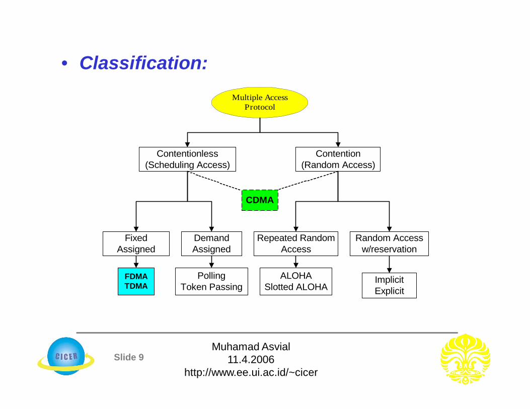
• Classification:Multiple Access
Protocol
Contention(Random Access)
Contentionless(Scheduling Access)
CDMA
FixedAssigned
DemandAssigned
FDMATDMA
PollingToken Passing
Repeated RandomAccess
ALOHASlotted ALOHA
Random Accessw/reservation
ImplicitExplicit

Slide 10Muhamad Asvial
11.4.2006http://www.ee.ui.ac.id/~cicer
Frequency Division Multiple Access
1 2 n
B
FRAME
Guard band (at the edges & between) tominimize crosstalk
Frequency 1
...
Frequency 2
Frequency n
Frequency 1
...
Frequency 2
Frequency n
Circuit Circuit
Circuit
Circuit Circuit
Circuit
Time Domain
FrequencyDomain
DownlinkPath
UplinkPath
Slide 11Muhamad Asvial
11.4.2006http://www.ee.ui.ac.id/~cicer
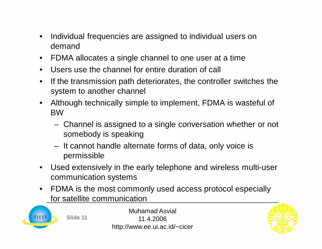
• Individual frequencies are assigned to individual users on demand
• FDMA allocates a single channel to one user at a time• Users use the channel for entire duration of call• If the transmission path deteriorates, the controller switches the
system to another channel• Although technically simple to implement, FDMA is wasteful of
BW– Channel is assigned to a single conversation whether or not
somebody is speaking– It cannot handle alternate forms of data, only voice is
permissible• Used extensively in the early telephone and wireless multi-user
communication systems• FDMA is the most commonly used access protocol especially
for satellite communication

Slide 12Muhamad Asvial
11.4.2006http://www.ee.ui.ac.id/~cicer
FDMA• In a cluster, each user is assigned a portion of the available bandwidth
• Let – Ndata = number of data channel– Nctl = number of control channel
• Total Bandwidth
• Number of Channels
,s data ctlN N Nor N
2s s c gB N B B
2s gs
c
B BN N
B
2s data c ctl c gB N B N B B
data c sN B B
Channel1
Channel2 ...... Channel
Ns
Bs
BcBg MHz
Slide 13Muhamad Asvial
11.4.2006http://www.ee.ui.ac.id/~cicer
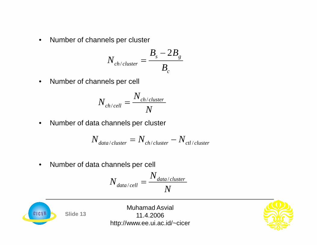
• Number of channels per cluster
• Number of channels per cell
• Number of data channels per cluster
• Number of data channels per cell
/
2s gch cluster
c
B BN
B
//
ch clusterch cell
NNN
/ / /data cluster ch cluster ctl clusterN N N
//
data clusterdata cell
NNN
Slide 14Muhamad Asvial
11.4.2006http://www.ee.ui.ac.id/~cicer
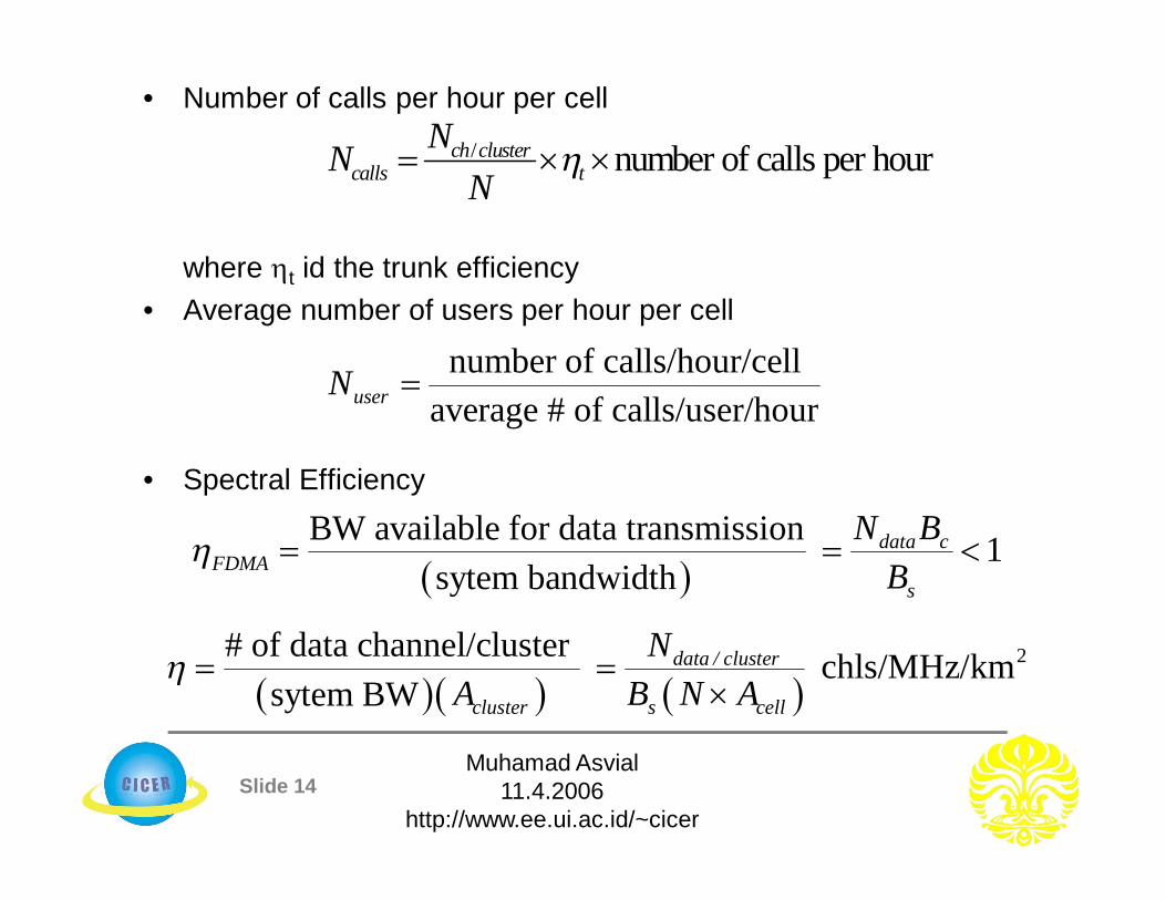
• Number of calls per hour per cell
where t id the trunk efficiency• Average number of users per hour per cell
• Spectral Efficiency
number of calls/hour/cellaverage # of calls/user/houruserN
2# of data channel/cluster chls/MHz/km
sytem BWdata / cluster
cluster s cell
NA B N A
/ number of calls per hourch clustercalls t
NNN
BW available for data transmission 1
sytem bandwidthdata c
FDMAs
N BB

Slide 15Muhamad Asvial
11.4.2006http://www.ee.ui.ac.id/~cicer
• FDMA Capacity
• Note that some textbooks will not account for guard bands in-between users. However, we can also have
– This will modify some of the above equation slightly
s
s c g
BCN B B
Channel1
Channel2 ...... Channel
Ns
Bs
Bc
Bg
MHz
Guard Bands

Slide 16Muhamad Asvial
11.4.2006http://www.ee.ui.ac.id/~cicer
• Spectral Efficiency, :– Definition 1
– Definition 2
– Also defined as the ratio of the bit rate to channel bandwidth expressed in bit per second per hertz (b/s/Hz)
Efficiency of TDMA Systems
2Total number of data channels channels/MHz/km
total coverage areasytem bandwidth
2Total traffic carried by system /MHz/km
total coverage areasytem bandwidthErlang
21 log 2, bits/s/Hzb
b
R MB BT
Slide 17Muhamad Asvial
11.4.2006http://www.ee.ui.ac.id/~cicer
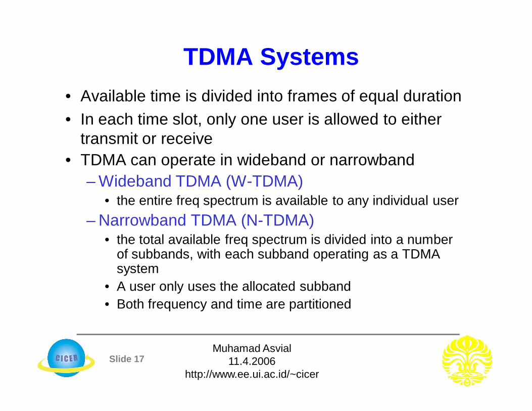
TDMA Systems• Available time is divided into frames of equal duration• In each time slot, only one user is allowed to either
transmit or receive• TDMA can operate in wideband or narrowband
– Wideband TDMA (W-TDMA)• the entire freq spectrum is available to any individual user
– Narrowband TDMA (N-TDMA)• the total available freq spectrum is divided into a number
of subbands, with each subband operating as a TDMA system
• A user only uses the allocated subband• Both frequency and time are partitioned
Slide 18Muhamad Asvial
11.4.2006http://www.ee.ui.ac.id/~cicer
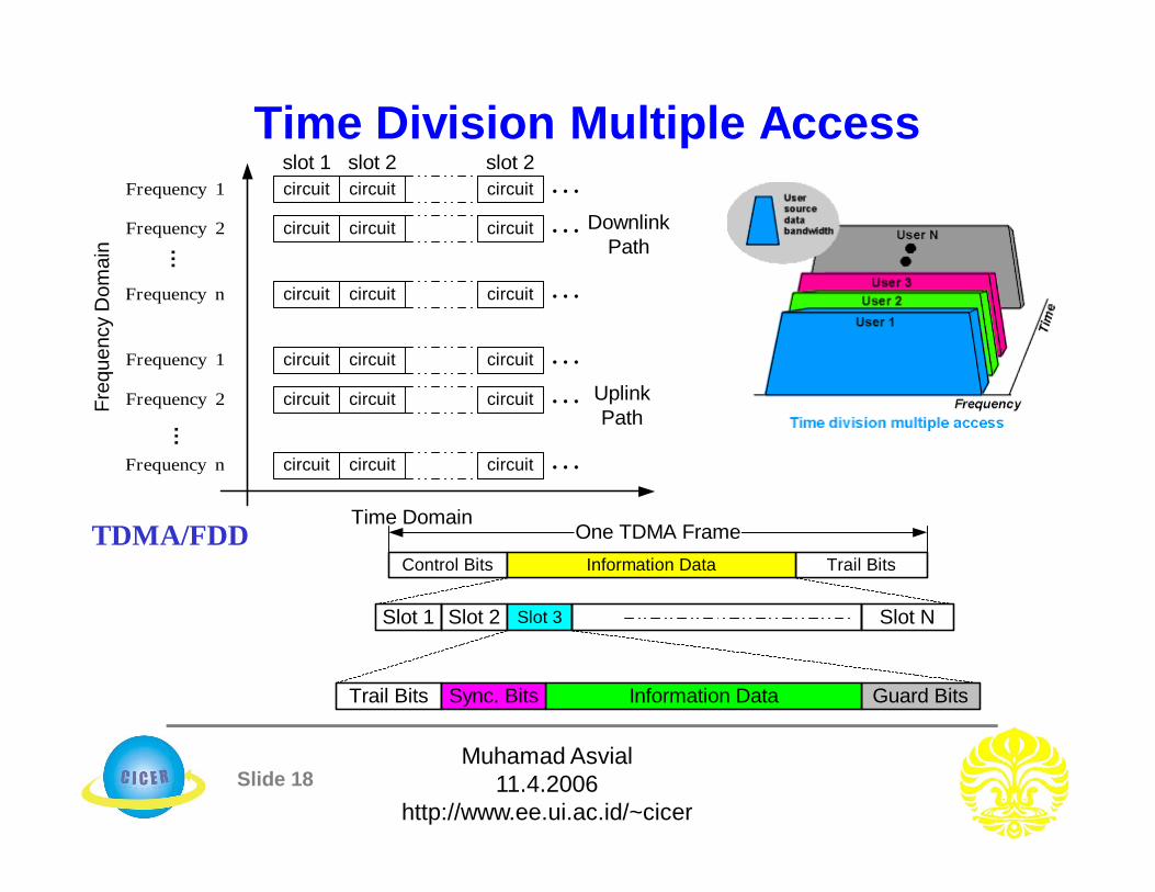
Time Division Multiple AccessFrequency 1
...
Frequency 2
Frequency n
Frequency 1
...
Frequency 2
Frequency n
Time Domain
Freq
uenc
y D
omai
n
circuit circuit circuit
circuit circuit circuit
circuit circuit circuit
circuit circuit circuit
circuit circuit circuit
circuit circuit circuit
DownlinkPath
UplinkPath
slot 1 slot 2 slot 2
Control Bits
Slot 1
Trail BitsInformation Data
Slot 2 Slot 3 Slot N
Guard BitsInformation DataTrail Bits Sync. Bits
One TDMA FrameTDMA/FDD

Slide 19Muhamad Asvial
11.4.2006http://www.ee.ui.ac.id/~cicer
• The number of time slots per frame is a design parameter depending on requirements such as modulation, bandwidth, data rate, etc.
• TDMA transmits data in a “buffer-and-burst” technique and hence transmission is not continuous– low battery consumption is achieved, and
simplification of handoff process is achievable• Transmission from users are interlaced into cyclic
time structure• Since different transceivers are used for
communication, duplexer may not be required• TDMA requires very high data rate compared to
FDMA and hence equalization is not required

Slide 20Muhamad Asvial
11.4.2006http://www.ee.ui.ac.id/~cicer
Time Division Multiple Access• Available time is divided into frames of equal
duration
• In each time slot, only one user is allowed to either transmit or receive
• Guard time separates the users
Control Bits
Slot 1
Trail BitsInformation Data
Slot 2 Slot 3 Slot N
Guard BitsInformation DataTrail Bits Sync. Bits
One TDMA Frame

Slide 21Muhamad Asvial
11.4.2006http://www.ee.ui.ac.id/~cicer
TDMA Operation
Slide 22Muhamad Asvial
11.4.2006http://www.ee.ui.ac.id/~cicer
Advantages:• No inter-modulation impairment
– Since TDMA uses one carrier at a time• No interference from other simultaneous transmissions
– TDMA’s technology separates users in time ensuring that they will not experience interference from other simultaneous transmissions
• Flexibility– TDMA can be easily adapted for the transmission of data or
voice• Variable rates
– TDMA offers the ability to carry data rates of 64 kbps to 120 Mbps (expandable in multiples of 64 kbps)
– This enables operators to offer personal communication services including fax, voice-band data, and short message services as well as bandwidth-intensive applications such as multimedia and videoconferencing
Slide 23Muhamad Asvial
11.4.2006http://www.ee.ui.ac.id/~cicer
• Bandwidth efficient protocol– TDMA uses bandwidth more effectively because no
frequency guard bands are required between channels• Low power consumption
– since transmission is bursty and non-continuous– i.e, TDMA provides the user with extended battery life and
talk time since the mobile is only transmitting a portion of the time (from 1/3 to 1/10) during conversations
• Guard time between time slots may be used to accommodate– clock instability– delay spread– transmission (or propagation) delays and pulse spreading
• Achieves selectivity in time domain, and selectivity is simpler than FDMA
• TDMA devices can be mass produced by VLSI giving rise to low cost
Slide 24Muhamad Asvial
11.4.2006http://www.ee.ui.ac.id/~cicer
• TDMA offers the possibility of a frame monitoring of signal strength (or BER) to enable better handoff strategies
• Ideal for digital communications– TDMA is also the most cost-effective technology for
upgrading a current AMPS analog system to digital• Ideal for satellite on-board processing• TDMA is the only technology that offers an efficient utilization of
hierarchical cell structures offering pico, micro, and macrocells• Hierarchical cell structures allow coverage for the system to be
tailored to support specific traffic and service needs– By using this approach, system capacities of more than 40-
times AMPS can be achieved in a cost-efficient way• Because of its inherent compatibility with FDMA analog
systems, TDMA allows service compatibility with the use of dual-mode handsets

Slide 25Muhamad Asvial
11.4.2006http://www.ee.ui.ac.id/~cicer
Disadvantage• In TDMA, each user has a predefined time slot. However, users
roaming from one cell to another are not allotted a time slot– Thus, if all the time slots in the next cell are already
occupied, a call might well be disconnected • Likewise, if all the time slots in the cell in which a user happens
to be in are already occupied, a user will not receive a dial tone • TDMA is subjected to multipath distortion because of its
sensitivity to timing– Even at thousandths of seconds, these multipath signals
cause problems• Overall TDMA is more complex and costly compared to FDMA

Slide 26Muhamad Asvial
11.4.2006http://www.ee.ui.ac.id/~cicer
• Wideband TDMA (W-TDMA)– the entire frequency spectrum is available to any
individual user• Narrowband TDMA (N-TDMA)
– the total available frequency spectrum is divided into a number of subbands, with each subband operating as a TDMA system
– A user only uses the allocated subband– both frequency and time are partitioned
TDMA Systems
Slide 27Muhamad Asvial
11.4.2006http://www.ee.ui.ac.id/~cicer
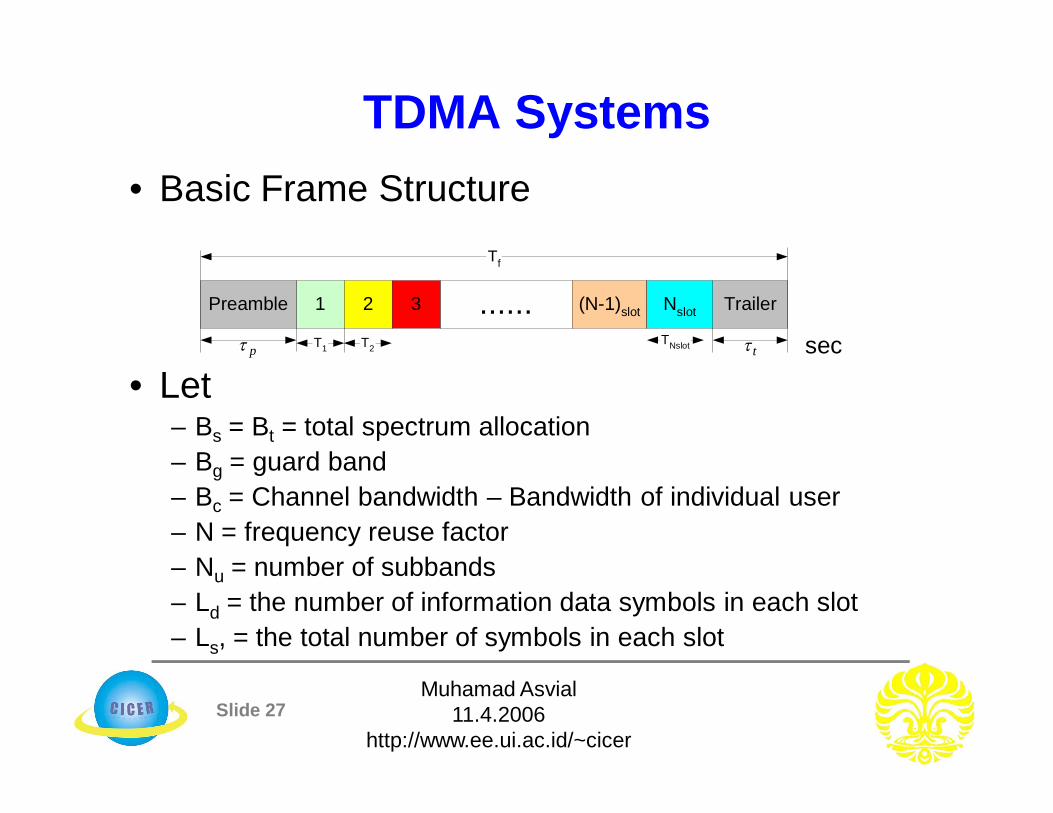
TDMA Systems• Basic Frame Structure
• Let– Bs = Bt = total spectrum allocation– Bg = guard band– Bc = Channel bandwidth – Bandwidth of individual user– N = frequency reuse factor– Nu = number of subbands– Ld = the number of information data symbols in each slot– Ls, = the total number of symbols in each slot
1 2 ...... (N-1)slot TrailerPreamble
Tf
T1 sec
Nslot3
T2TNslotp t
Slide 28Muhamad Asvial
11.4.2006http://www.ee.ui.ac.id/~cicer
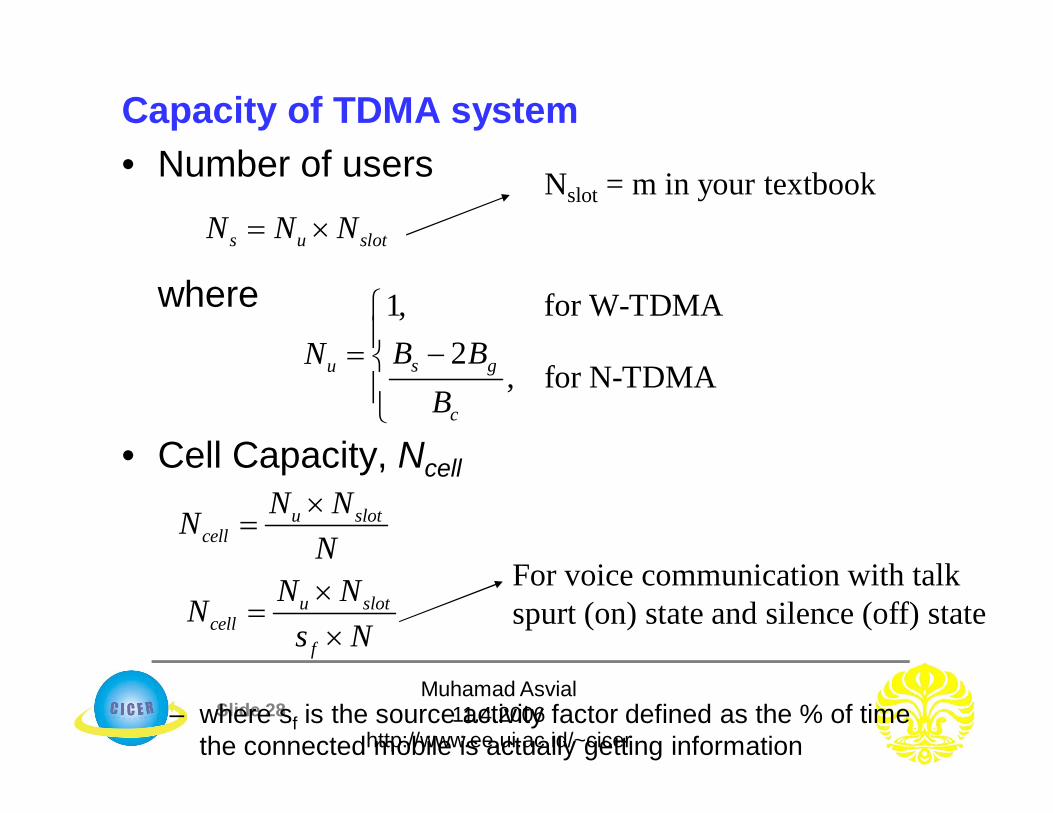
Capacity of TDMA system• Number of users
where
• Cell Capacity, Ncell
– where sf is the source activity factor defined as the % of time the connected mobile is actually getting information
s u slotN N N
1, for W-TDMA2
, for N-TDMAs gu
c
B BNB
u slotcell
N NNN
u slotcell
f
N NNs N
For voice communication with talk spurt (on) state and silence (off) state
Nslot = m in your textbook

Slide 29Muhamad Asvial
11.4.2006http://www.ee.ui.ac.id/~cicer
• Overhead bits per frame
where– bOH =overhead bits per frame– Nr = # of reference burst per frame– br = # of overhead bits per frame– bp = # of overhead bits per preamble in each time slot– bg = # of equivalent bits in each guard time interval
• Total number of traffic bits per frame
• Frame efficiency
OH r r t p t g r gb N b N b N b N b
T fb T R where R = channel bit rate
1 100%OHf
T
bb
Slide 30Muhamad Asvial
11.4.2006http://www.ee.ui.ac.id/~cicer
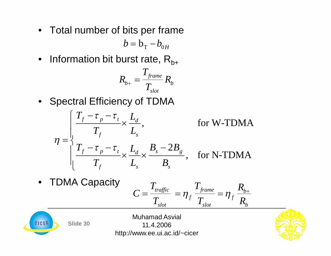
• Total number of bits per frame
• Information bit burst rate, Rb+
• Spectral Efficiency of TDMA
• TDMA Capacity
T 0b Hb b
frameb b
slot
TR R
T
, for W-TDMA
2, for N-TDMA
f p t d
f s
f p t s gd
f s s
T LT L
T B BLT L B
traffic frame bf f
slot slot b
T T RCT T R

Slide 31Muhamad Asvial
11.4.2006http://www.ee.ui.ac.id/~cicer
Code Division Multiple Access• CDMA technology focuses primarily on the “DSSS” technique • Instead of using freq or time slots, it uses digital codes to distinguish
between multiple users• Each user is assigned a unique PN code sequence• The assigned code is uncorrelated with the data • Because the signals are distinguished by digital codes, many users can
share the same bandwidth simultaneously– i.e., signals are transmitted in the same frequency at the same time
• Multiplying the data by the high data rate PN code results in dividing the signal into smaller bits, thus, increasing its BW
• The PN code used for spreading must have – low cross-correlation values and – be unique to every user
• This is the reason why a Rx which has knowledge about the code of the intended Tx is capable of selecting the desired signal
Slide 32Muhamad Asvial
11.4.2006http://www.ee.ui.ac.id/~cicer
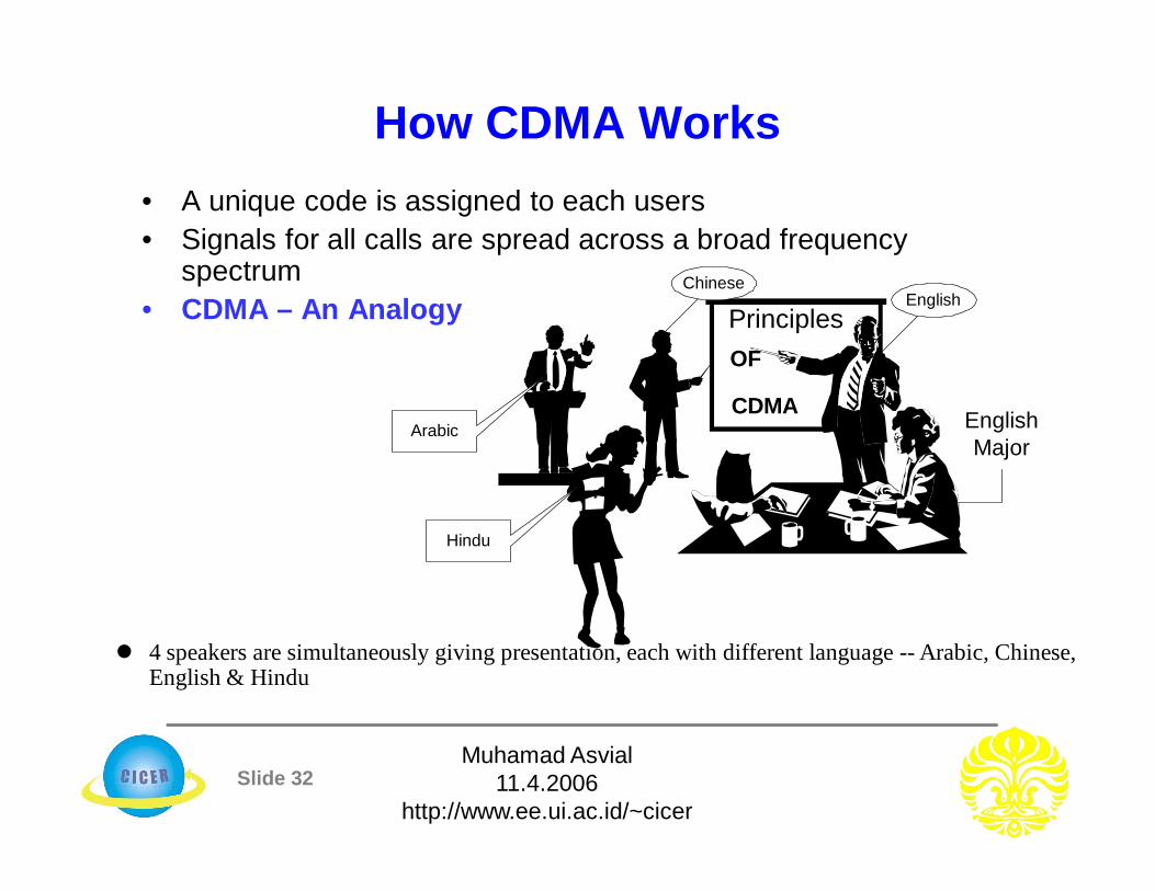
How CDMA Works• A unique code is assigned to each users• Signals for all calls are spread across a broad frequency
spectrum• CDMA – An Analogy
CDMA
PrinciplesOF
EnglishChinese
Hindu
Arabic EnglishMajor
4 speakers are simultaneously giving presentation, each with different language -- Arabic, Chinese, English & Hindu
Slide 33Muhamad Asvial
11.4.2006http://www.ee.ui.ac.id/~cicer
– You are in the audience, and English is your native language– You only understand the words of the English speaker and tune out
the Arabic, Chinese, and Hindu speakers• You hear only what you know and recognize
– This is the general idea of CDMA systems• Multiple users share the same frequency band at the same time,
yet each user can only recognize his or her own code• This technique allows numerous phone calls to be
simultaneously transmitted in one radio frequency band– Coded conversations are encoded/decoded for each user– At Tx, signal is first “correlated” with the PN code sequence– At Rx, the spread signal is “demodulated” and decorrelated
using unique PN code• A signal correlated with a given PN code and decorrelated with
the same PN code returns the original signal
Slide 34Muhamad Asvial
11.4.2006http://www.ee.ui.ac.id/~cicer
• IS-95 (CDMA)– After the development of the IS-54 standard,
Qualcomm, a San Diego-based company, developed a new digital cellular system design utilizing Code Division Multiple Access (CDMA)
– This is known as IS-95– Unlike IS-54, which utilizes the same 30-kHz
(same as AMPS), IS-95 uses a SS signal with 1.2288 MHz spreading bandwidth• a frequency span equivalent to 41 AMPS channels
– IS-95 has been shown to theoretically offer greater traffic capacity than TDMA
Practical Example

Slide 35Muhamad Asvial
11.4.2006http://www.ee.ui.ac.id/~cicer
Advantages:1. Voice Activities Cycles
– CDMA is the only one technique that succeeds in taking advantage of the nature of human conversation
– In CDMA, all the users are sharing one radio channel– The human voice activity cycle is 35%, the rest of the time we are
listening– Because each channel user is active just 35% of the entire cycle,
all others benefit with less interference in a single CDMA radio channel
– So, the mutual interference is in a nice-free way, reduced by 65%; and thus, the channel capacity is increased about 3 times
2. Improved call quality, with better and more consistent sound as compared to other systems
Advantages & Disadvantages

Slide 36Muhamad Asvial
11.4.2006http://www.ee.ui.ac.id/~cicer
3. No Equalizer Needed– When the transmission rate is much higher than 10 kbps in both FDMA and
TDMA, an equalizer is required– On the other hand, CDMA only needs a correlator, which is cheaper than the
equalizer4. No Hard Handoff
– In CDMA, every cell uses the same radio– This feature avoids the process of handoff from one freq to another while
moving from one cell to another5. No Guard Time in CDMA
– TDMA requires the use of guard time between time slots• guard time does occupy the time interval for some info bits
– This “waste” of bits does not exists in CDMA, because guard time is not needed in CDMA technique

Slide 37Muhamad Asvial
11.4.2006http://www.ee.ui.ac.id/~cicer
6. Less Fading– Less fading is observed in the wide-band signal while propagating in a mobile
ratio environment7. Capacity Advantage
– Given correct parameters, CDMA can have as much as four times the TDMA capacity; and twenty times FDMA capacity per channel/cell
8. No frequency management or assignment needed– In both, TDMA and FDMA, the frequency management is always a critical– Since there is only one channel in CDMA, no frequency management is
needed9. Enhanced privacy
– CDMA signals resistant to interception or jamming

Slide 38Muhamad Asvial
11.4.2006http://www.ee.ui.ac.id/~cicer
10. Soft Capacity– Because in CDMA all the traffic channels share a single
radio channel, we can add one additional user so the voice quality is just slightly degraded
11. Coexistence– Both systems, analog and CDMA can operate in two
different spectra, with no interference at all12. Simplified system planning through the use of the same
frequency in every sector of every cell– Improved coverage characteristics, allowing for the
possibility of fewer cell sites13. Increased talk time for portables14. Bandwidth on demand
Slide 39Muhamad Asvial
11.4.2006http://www.ee.ui.ac.id/~cicer
Disadvantages:1. Capacity not well defined
– The capacity of CDMA systems is not well defined. The effective (Eb/No) formula demonstrates the interference-limited nature of the system, but more than one factor in that formula is affected by the number of users, making it hard to gauge how performance degrades as a function of users
2. The Near-Far Problem– The main problem with applying DS/CDMA is the so-
called “Near-Far” effect– This effect is present when an interfering Tx is much
closer to the Rx than the intended Tx – Assume there are 2 users, one near the base and one far
from the base as shown

Slide 40Muhamad Asvial
11.4.2006http://www.ee.ui.ac.id/~cicer
• Although the cross-correlation between codes A and B is low, the correlation between the received signal from the interfering Rx and code A can be higher than the correlation between the received signal from the intended Rx and code A
• In CDMA, stronger received signal levels raise the noise floor at the base station demodulators for the weaker signals, thereby decreasing the probability that weaker signals will be received
• The result is that proper data detection is not possible
Near-Far effect illustrated
Slide 41Muhamad Asvial
11.4.2006http://www.ee.ui.ac.id/~cicer
• To help eliminate the “Near-Far” effect, power control is used– Base Station (BS) rapidly samples the signal strength of each
mobile and then sends a power change command over the forward link
– This sampling is done 800 times per second and can be adjusted in 84 steps of 1 dB
• The purpose of this is so that the received powers from all users are roughly equal
• That is, when a mobile unit is close to a BS, its power output is lower– the mobile unit transmits only at the power necessary to maintain
connection• This solves the problem of a nearby subscriber overpowering the BS
receiver and drowning out the signals of far away subscribers• An extra benefit of power control is extended battery life

Slide 42Muhamad Asvial
11.4.2006http://www.ee.ui.ac.id/~cicer
• Universal Frequency Reuse– Uses one universal cell frequency reuse pattern applies
• This turns out to be beneficial and improves the capacity of the system
• Ease of freq management is also found in DS/CDMA• Power Control
– Reverse Link (from mobile unit to base station)• link is designed to be asynchronous and is susceptible to the
“near-far” problem• In order to remedy this, the use of power control is employed
– To ensure all signals from the mobiles with a given cell arrive at the base of the cell with equal power
– To maximize the total user capacity – To minimize power consumption of portable units
Characteristic of DS/CDMA
Slide 43Muhamad Asvial
11.4.2006http://www.ee.ui.ac.id/~cicer
• Effective use of the power control will ensure that power control must be accurate and fast enough to compensate for fading
–Forward Link (from base station to mobile unit) • Link does not suffer much from near-far problem since all
cell signals can be received at the mobile with equal power• When at excessive intercell interference, the power control
can be applied by increasing the power to the mobile

Slide 44Muhamad Asvial
11.4.2006http://www.ee.ui.ac.id/~cicer
Some CDMA Analysis• Users are identified by unique code sequence• Let
– K = number of users– dk = k-th users baseband data sequence, with amplitude 1– ak = k-th users spreading code sequence, with amplitude 1
– Please note that ak(t) and dk(t) are completely independent
b
bk ki ki T b
i ib
t iTd s s P t iTt T
c
ck kl kl T c
l lc
t lTa a a P t lTt T

Slide 45Muhamad Asvial
11.4.2006http://www.ee.ui.ac.id/~cicer
• CDMA Transmitter
– First the data symbols dk(t) are spread into ak(t)dk(t)– Then spread signal is modulated (usually by PSK)– Notice that
L = Gp = number of chips per data symbol = processing gain
x BasebandBPF
PN CodeGenerator
Data signal Transmitted Signalxk(t)
Chip Clock
~ak(t)
dk(t)ak(t)dk(t) Modulator
cAcos t
1c
c
fT
bb c
c
TT LT LT
Slide 46Muhamad Asvial
11.4.2006http://www.ee.ui.ac.id/~cicer
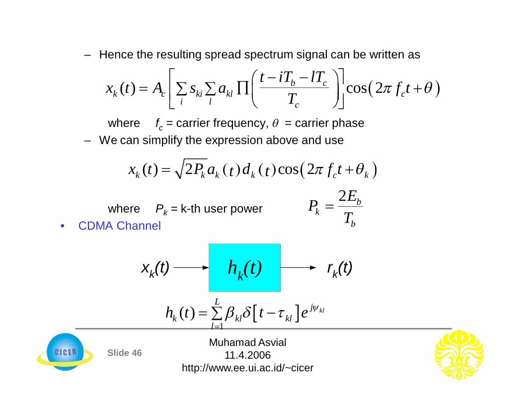
– Hence the resulting spread spectrum signal can be written as
where fc = carrier frequency, = carrier phase– We can simplify the expression above and use
where Pk = k-th user power• CDMA Channel
( ) cos 2b ck c ki kl c
i l c
t iT lTx t A s a f t
T
( ) 2 cos 2k k k k c kx t P a d f tt t
2 bk
b
EPT
1
( ) klL j
klk kll
th t e
hk(t)xk(t) rk(t)

Slide 47Muhamad Asvial
11.4.2006http://www.ee.ui.ac.id/~cicer
• CDMA Receiver– Signal is first demodulated and then despread– The signal is despread by the same amount through a
cross-correlation by locally generated PN sequence– i.e., demodulation is accomplished in part by remodulating
with the spreading code• This involves the correlation of the received signal with
the delayed version of the spreading signal (despreading operation)
• In other words, the received signal is multiplied again by a synchronized version of the PN code
0bT
dt kls
( )k da t T
r t
2 cos ( )k c kP t
Demodulator y t Decision
Device

Slide 48Muhamad Asvial
11.4.2006http://www.ee.ui.ac.id/~cicer
• CDMA system model (k-th user)
Notice that the despreading operation is similar to the spreading operation
X
ka t
kd t X +
r(t)
(t)n
X
ka (t-τ) c kAcos(ω t+ )
X ( )z0
Tdt
kls (t)ˆ
cAcos(ω t+ )kPN signalGenerator
Channel
Receiver
Transmitter
Slide 49Muhamad Asvial
11.4.2006http://www.ee.ui.ac.id/~cicer
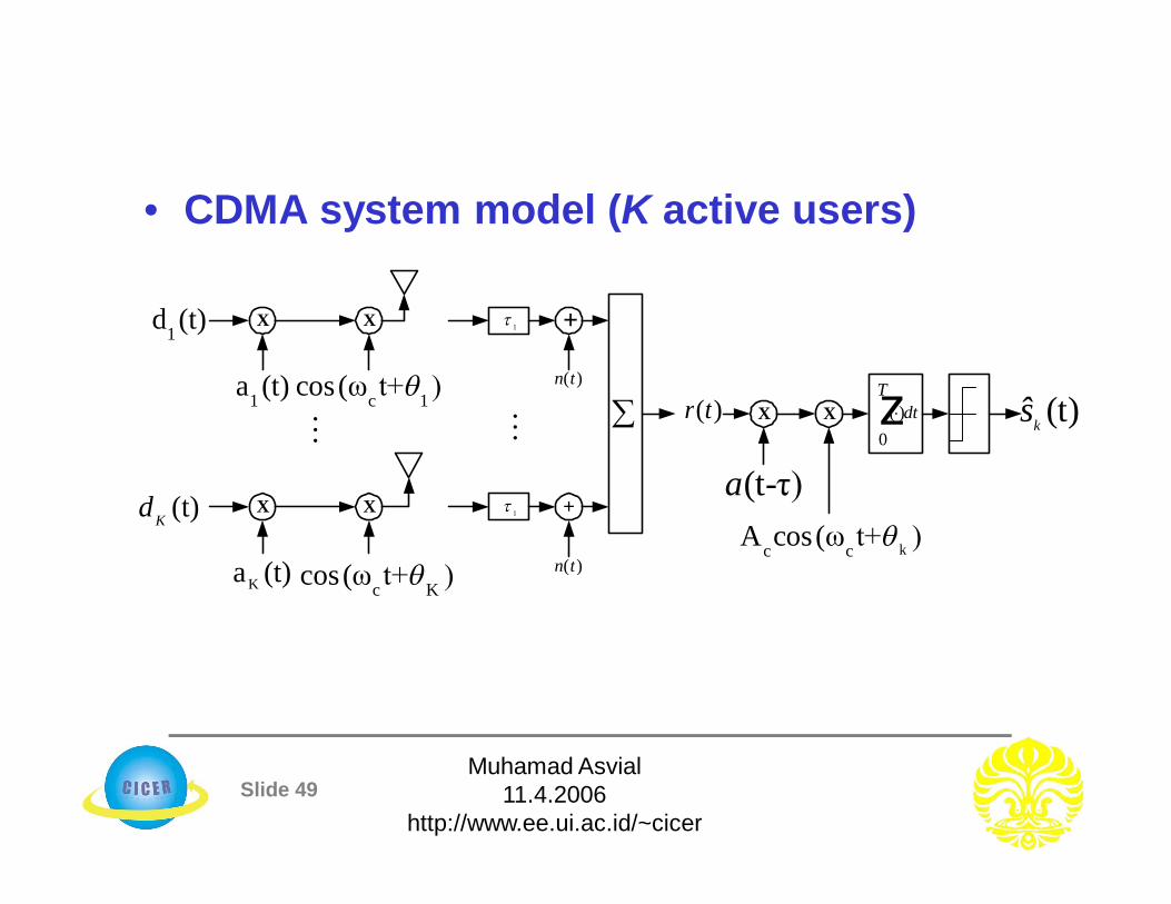
• CDMA system model (K active users)
X
1a (t)
1d (t) X 1
X
Ka (t)
(t)Kd X 1
+
+
r t( )
n t( )
n t( )
X
(t-τ)a
kc cA cos(ω t+ )
X ( )z0
Tdt (t)ksc 1cos(ω t+ )
c Kcos(ω t+ )
Slide 50Muhamad Asvial
11.4.2006http://www.ee.ui.ac.id/~cicer
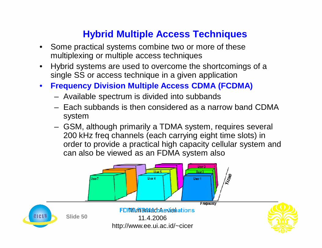
Hybrid Multiple Access Techniques• Some practical systems combine two or more of these
multiplexing or multiple access techniques• Hybrid systems are used to overcome the shortcomings of a
single SS or access technique in a given application • Frequency Division Multiple Access CDMA (FCDMA)
– Available spectrum is divided into subbands – Each subbands is then considered as a narrow band CDMA
system– GSM, although primarily a TDMA system, requires several
200 kHz freq channels (each carrying eight time slots) in order to provide a practical high capacity cellular system and can also be viewed as an FDMA system also
Slide 51Muhamad Asvial
11.4.2006http://www.ee.ui.ac.id/~cicer
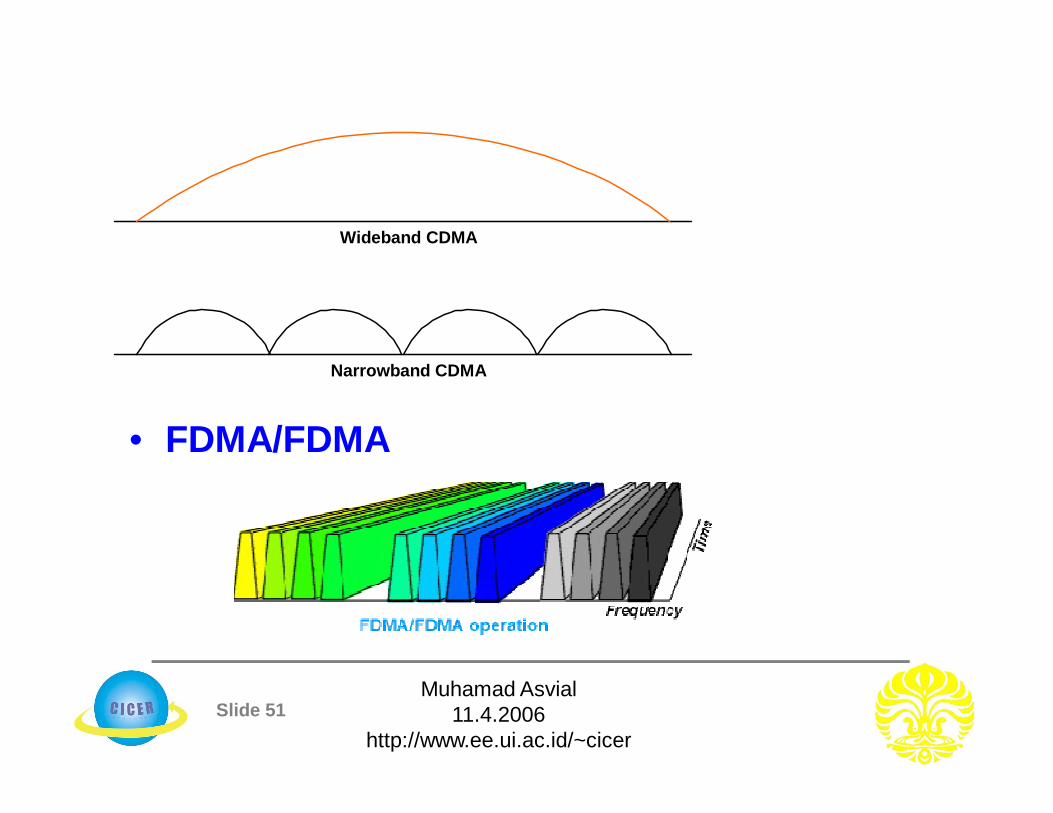
• FDMA/FDMA
Wideband CDMA
Narrowband CDMA

Slide 52Muhamad Asvial
11.4.2006http://www.ee.ui.ac.id/~cicer
• Direct Sequence Frequency Hopping Multiple Access (DS/FHMA)– One data bit is divided into frequency-hop channels (fc)– In each frequency-hop channel one complete PN-code of
length NFH is added to the data signal– Since FH-sequence and PN-codes are coupled, every
receiver is identified by a combination of an FH-sequence and PN-codes

Slide 53Muhamad Asvial
11.4.2006http://www.ee.ui.ac.id/~cicer
• Time Division CDMA (TCDMA)– Different spreading codes are assigned to different cells– Within each cell, only one user is allocated a particular time
slot such that only one user is transmitting in each cell at one slot
• Time Division Frequency Hopping (TDFH)– At the start of a new TDMA frame, the user hops to a new
channel– This avoids severe fades or erasure in any particular
channel– The user is allowed to hop according to a predefined
sequence– TXs are made to transmit on different freqs at different times
Slide 54Muhamad Asvial
11.4.2006http://www.ee.ui.ac.id/~cicer
• Space Division Multiple Access (SDMA) – Also called multiple beam frequency reuse– Different areas of the cell is covered by multiple
beam antenna system– Makes use of orthogonality in geometry (spatial
channel separation)– Each of the coverage area may use either FDMA,
TDMA or CDMA– An example of SDMA is sectored antennas – Adaptive antennas (or smart antennas) is most
likely to be used for the future for the realization of SDMA