Multiple Subchannel Sets: An Implementation · PDF file2 Multiple Subchannel Sets: An...
20
© Copyright IBM Corp. 2008. All rights reserved. ibm.com/redbooks 1 Redpaper Multiple Subchannel Sets: An Implementation View The purpose of this IBM® Redpaper is to demonstrate a pragmatic implementation approach for the adoption of Multiple Subchannel Sets (MSS) in a System z™ environment. MSS provides relief for I/O device configurations in large System z10™ and System z9™ environments. It also increases Parallel Access Volumes (PAVs) connectivity. The following IBM protocols support MSS: Enterprise Systems Connection (ESCON®) Fibre Connection (FICON®) z/OS® The IBM System Storage™ and the System z™ support PAVs.
Transcript of Multiple Subchannel Sets: An Implementation · PDF file2 Multiple Subchannel Sets: An...
Redpaper
Multiple Subchannel Sets: An Implementation View
The purpose of this IBM® Redpaper is to demonstrate a pragmatic implementation approach for the adoption of Multiple Subchannel Sets (MSS) in a System z™ environment.
MSS provides relief for I/O device configurations in large System z10™ and System z9™ environments. It also increases Parallel Access Volumes (PAVs) connectivity.
The following IBM protocols support MSS:
� Enterprise Systems Connection (ESCON®)� Fibre Connection (FICON®)� z/OS®
The IBM System Storage™ and the System z™ support PAVs.
© Copyright IBM Corp. 2008. All rights reserved. ibm.com/redbooks 1

MSS description
The following servers support MSS functionality:
� System z10� System z9
Subchannel numbers
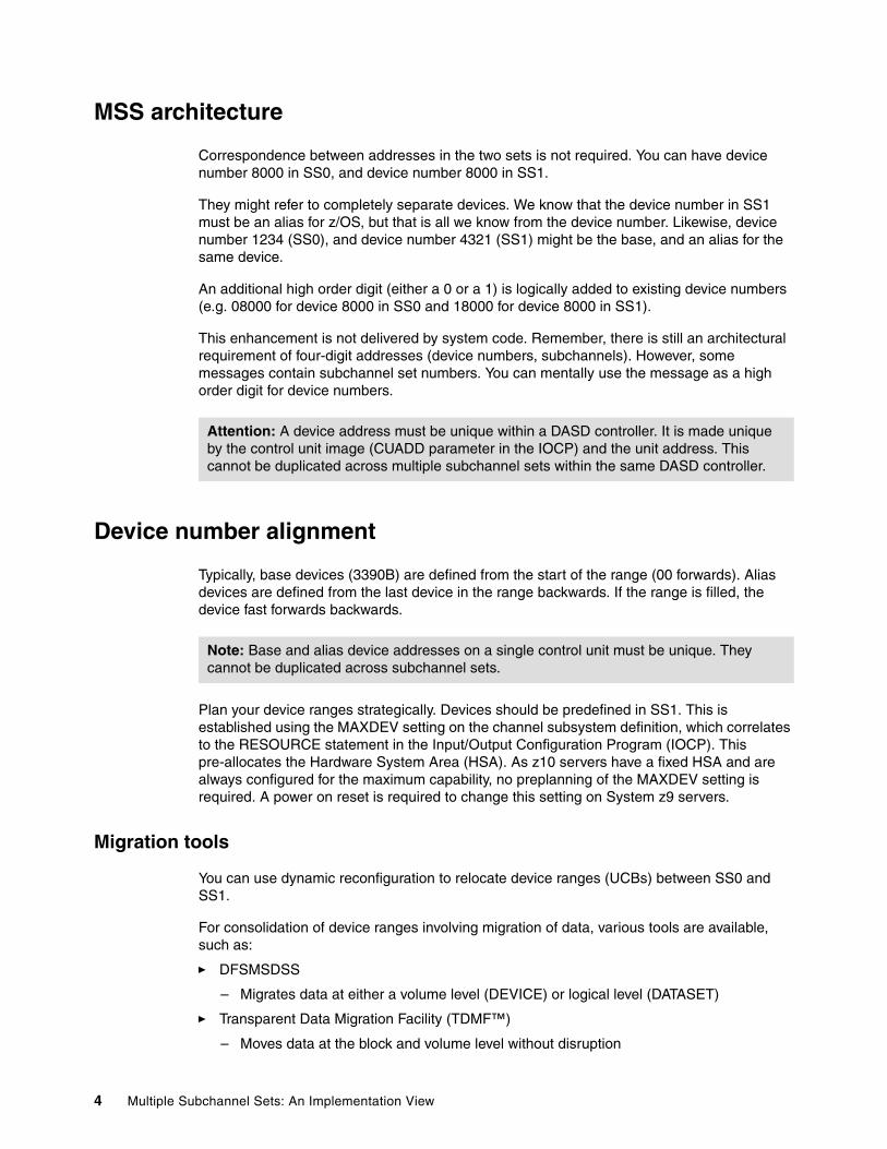
Subchannel numbers (including their implied path information to a device) are limited to four hexadecimal digits by hardware and software architectures. These four hexadecimal digits provide 64 K addresses, also known as a set.
IBM has 256 reserved subchannels. That leaves 63.75 K subchannels for general use with the System z10 and System z9 servers.
PAV has made this limitation of subchannels a challenge for larger installations. A single disk drive (with PAV) often consumes at least four subchannels.
Removing these constraints is difficult because four hexadecimal digits for subchannels (and device numbers corresponding to subchannels) are used in a number of places. Simply expanding the field would break too many programs.
The solution gives you the ability to have sets of subchannels (addresses), with a current implementation of two sets. Each set provides 64 K addresses.
� Subchannel set 0 (SS0)
– Reserves subchannels for IBM use. Although, the number of reserved subchannels (256) on the System z10 and System z9 is less than on z990, and z890 servers (1024)
� Subchannel set 1 (SS1)
– Provides a full range of 64 K subchannels on System z10 and System z9 servers.
Figure 1 on page 3 shows the System z server with MSS
Note: Do not confuse MSS with multiple Channel Subsystems (CSS). In most cases a subchannel represents an addressable device. For example, a disk control unit with 30 drives uses 30 subchannels. An addressable device is associated with a device number.
Note: Each CSS has its own SS0 and SS1.
2 Multiple Subchannel Sets: An Implementation View
Figure 1 System z server with MSS
MSS–implementation considerations
When you implement MSS, you must understand and have access to the following information:
� Hardware requirements� Software requirements� MSS architecture� Device number alignment � Migration tools � Disk subsystem considerations� Numbering schemes� PAV implementation
Each implementation consideration is described in detail in the remaining sections of this publication.
Hardware requirements
Only System z10 and System z9 servers support MSS.
Software requirements
MSS requires z/OS 1.7 and above.
System z Server
Channels Channels ChannelsChannels
Partitions Partitions Partitions Partitions
Logical Channel Subsystem 0
Logical Channel Subsystem 1
Logical Channel Subsystem 2
Logical Channel Subsystem 3
Up to 15Logical Partitions
Up to 15Logical Partitions
Up to 15Logical Partitions
Up to 15Logical Partitions
CSS-3 Subchannels
SS -1SS-0
CSS-2 Subchannels
SS-1SS-0
CSS-1 Subchannels
SS-1SS-0
CSS-0 Subchannels
SS-1SS-0
63.75K63.75K 63.75K 63.75K64K64K 64K64K
Multiple Subchannel Sets MSS
Note: Logical partitions (LPARS) with earlier versions of z/OS do not see devices in SS1.
Multiple Subchannel Sets: An Implementation View 3
MSS architecture
Correspondence between addresses in the two sets is not required. You can have device number 8000 in SS0, and device number 8000 in SS1.
They might refer to completely separate devices. We know that the device number in SS1 must be an alias for z/OS, but that is all we know from the device number. Likewise, device number 1234 (SS0), and device number 4321 (SS1) might be the base, and an alias for the same device.
An additional high order digit (either a 0 or a 1) is logically added to existing device numbers (e.g. 08000 for device 8000 in SS0 and 18000 for device 8000 in SS1).
This enhancement is not delivered by system code. Remember, there is still an architectural requirement of four-digit addresses (device numbers, subchannels). However, some messages contain subchannel set numbers. You can mentally use the message as a high order digit for device numbers.
Device number alignment
Typically, base devices (3390B) are defined from the start of the range (00 forwards). Alias devices are defined from the last device in the range backwards. If the range is filled, the device fast forwards backwards.
Plan your device ranges strategically. Devices should be predefined in SS1. This is established using the MAXDEV setting on the channel subsystem definition, which correlates to the RESOURCE statement in the Input/Output Configuration Program (IOCP). This pre-allocates the Hardware System Area (HSA). As z10 servers have a fixed HSA and are always configured for the maximum capability, no preplanning of the MAXDEV setting is required. A power on reset is required to change this setting on System z9 servers.
Migration tools
You can use dynamic reconfiguration to relocate device ranges (UCBs) between SS0 and SS1.
For consolidation of device ranges involving migration of data, various tools are available, such as:
� DFSMSDSS
– Migrates data at either a volume level (DEVICE) or logical level (DATASET)
� Transparent Data Migration Facility (TDMF™)
– Moves data at the block and volume level without disruption
Attention: A device address must be unique within a DASD controller. It is made unique by the control unit image (CUADD parameter in the IOCP) and the unit address. This cannot be duplicated across multiple subchannel sets within the same DASD controller.
Note: Base and alias device addresses on a single control unit must be unique. They cannot be duplicated across subchannel sets.
4 Multiple Subchannel Sets: An Implementation View

� Logical Data Migration Facility (LDMF)
– Migrates datasets at the volume level
– Typically used to consolidate smaller volumes
Disk subsystem considerations
We highly recommend that you contact your IBM System Storage representative prior to choosing a numbering scheme for your storage subsystem. Alternatively, contact your vendor for guidance of non-IBM storage subsystems.
Numbering schemes
When choosing a number scheme, you will not find just one correct approach for all circumstances. The approach you choose will vary depending on the customer requirements.
In this section we are going to demonstrate different options for you.
The numbering schemes are the following:
� Scheme 1- Compacting or rolling reuse of addresses
– Device numbers available to SS0 and SS1 are used on an “as available” basis.
� Scheme 2 - Direct access storage device (DASD) versus the rest
– The device numbers used by alias volumes (3390A) are assigned to SS1, then reused in SS0 for non-DASDs.
� Scheme 3 - Device Pairing
– The first half of an LSS range (128 addresses) is allocated to the base (3390B) range. The same device range is reused for the next consecutive assignment of devices within SS1.
� Scheme 4 - Filling the ranges
– The device addresses in SS1 are amalgamated to complete ranges, then reused accordingly in SS0.
Scheme 1 - Compacting or rolling reuse of addresses
The numbering scheme duplicates ranges across SS0 and SS1 by using the unit address (UA) field for 3390A in SS1.
� 5000,72 UNITADD=00 in SS0
� 5000,184 UNITADD=48 in SS1
Compaction is achieved in both SS0 and SS1 by using the follow on numbers in each SS (5048 is next in SS0, 50B7 is next in SS1). This achieves maximum reuse of device numbers. However, it should be noted that this does look confusing as the device addresses in SS1 are allocated unit addresses that do not match the numbering scheme (Example 1).
Example 1 IOCP use of the UNITADD for device range compaction
IODEVICE ADDRESS=(50B8,184),UNITADD=48, CUNUMBR=(5000),STADET=Y* ,DESC='IBM 2107 DASD',UNIT=3390A,SCHSET=1
Multiple Subchannel Sets: An Implementation View 5
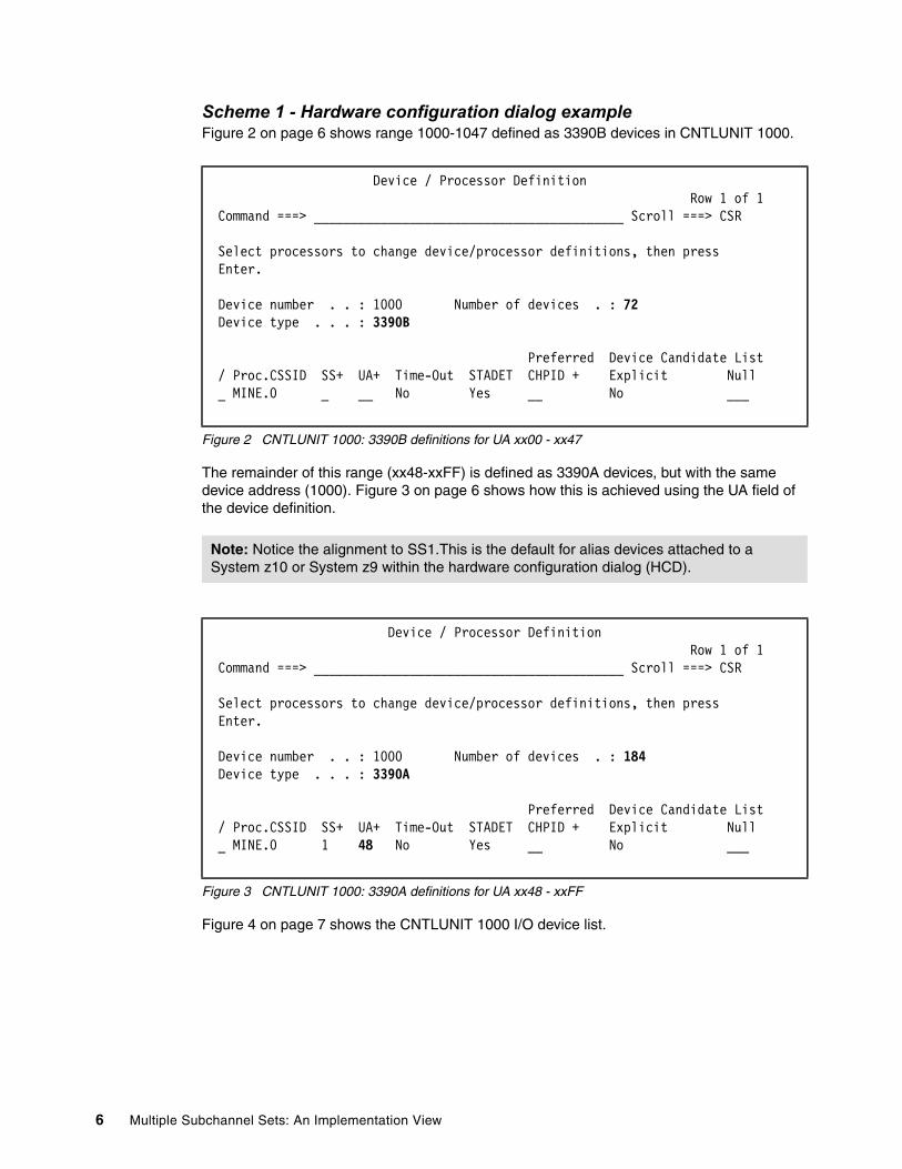
Scheme 1 - Hardware configuration dialog exampleFigure 2 on page 6 shows range 1000-1047 defined as 3390B devices in CNTLUNIT 1000.
Figure 2 CNTLUNIT 1000: 3390B definitions for UA xx00 - xx47
The remainder of this range (xx48-xxFF) is defined as 3390A devices, but with the same device address (1000). Figure 3 on page 6 shows how this is achieved using the UA field of the device definition.
Figure 3 CNTLUNIT 1000: 3390A definitions for UA xx48 - xxFF
Figure 4 on page 7 shows the CNTLUNIT 1000 I/O device list.
Device / Processor Definition Row 1 of 1 Command ===> __________________________________________ Scroll ===> CSR Select processors to change device/processor definitions, then press Enter. Device number . . : 1000 Number of devices . : 72 Device type . . . : 3390B Preferred Device Candidate List / Proc.CSSID SS+ UA+ Time-Out STADET CHPID + Explicit Null _ MINE.0 _ __ No Yes __ No ___
Note: Notice the alignment to SS1.This is the default for alias devices attached to a System z10 or System z9 within the hardware configuration dialog (HCD).
Device / Processor Definition Row 1 of 1 Command ===> __________________________________________ Scroll ===> CSR Select processors to change device/processor definitions, then press Enter. Device number . . : 1000 Number of devices . : 184 Device type . . . : 3390A Preferred Device Candidate List / Proc.CSSID SS+ UA+ Time-Out STADET CHPID + Explicit Null _ MINE.0 1 48 No Yes __ No ___
6 Multiple Subchannel Sets: An Implementation View
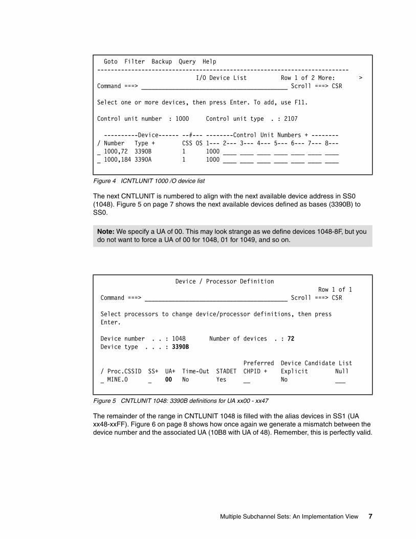
Figure 4 ICNTLUNIT 1000 /O device list
The next CNTLUNIT is numbered to align with the next available device address in SS0 (1048). Figure 5 on page 7 shows the next available devices defined as bases (3390B) to SS0.
Figure 5 CNTLUNIT 1048: 3390B definitions for UA xx00 - xx47
The remainder of the range in CNTLUNIT 1048 is filled with the alias devices in SS1 (UA xx48-xxFF). Figure 6 on page 8 shows how once again we generate a mismatch between the device number and the associated UA (10B8 with UA of 48). Remember, this is perfectly valid.
Goto Filter Backup Query Help -------------------------------------------------------------------------- I/O Device List Row 1 of 2 More: > Command ===> ___________________________________________ Scroll ===> CSR Select one or more devices, then press Enter. To add, use F11. Control unit number : 1000 Control unit type . : 2107 ----------Device------ --#--- --------Control Unit Numbers + -------- / Number Type + CSS OS 1--- 2--- 3--- 4--- 5--- 6--- 7--- 8--- _ 1000,72 3390B 1 1000 ____ ____ ____ ____ ____ ____ ____ _ 1000,184 3390A 1 1000 ____ ____ ____ ____ ____ ____ ____
Note: We specify a UA of 00. This may look strange as we define devices 1048-8F, but you do not want to force a UA of 00 for 1048, 01 for 1049, and so on.
Device / Processor Definition Row 1 of 1 Command ===> __________________________________________ Scroll ===> CSR Select processors to change device/processor definitions, then press Enter. Device number . . : 1048 Number of devices . : 72 Device type . . . : 3390B Preferred Device Candidate List / Proc.CSSID SS+ UA+ Time-Out STADET CHPID + Explicit Null _ MINE.0 _ 00 No Yes __ No ___
Multiple Subchannel Sets: An Implementation View 7

Figure 6 CNTLUNIT 1048: 3390A definitions for UA xx48 - xxFF
Figure 7 on page 8 shows the device list for CNTLUNIT 1048.
Figure 7 CNTLUNIT 1048 I/O device list
Scheme 1 - IOCP statements exampleExample 2 shows the IOCP statements demonstrating scheme 1 with device range compaction.
Example 2 IOCP statements with device range compaction
CNTLUNIT CUNUMBR=1000,PATH=((CSS(0),04,08,2C,31,33,37,6F,75)),* UNITADD=((00,256)),CUADD=0,UNIT=2107 IODEVICE ADDRESS=(1000,72),UNITADD=00,CUNUMBR=(1000),STADET=Y,* DESC='IBM 2107 DASD',UNIT=3390B IODEVICE ADDRESS=(1000,184),UNITADD=48,CUNUMBR=(1000),STADET=Y* ,DESC='IBM 2107 DASD',UNIT=3390A,SCHSET=1Ranges aligned to each subchannel set at this point:SS0: 1000-1047SS1 1000-10B7 CNTLUNIT CUNUMBR=1048,PATH=((CSS(0),04,08,2C,31,33,37,6F,75)),* UNITADD=((00,256)),CUADD=1,UNIT=2107 IODEVICE ADDRESS=(1048,72),UNITADD=00,CUNUMBR=(1048),STADET=Y,*
Device / Processor Definition Row 1 of 1 Command ===> __________________________________________ Scroll ===> CSR Select processors to change device/processor definitions, then press Enter. Device number . . : 10B8 Number of devices . : 184 Device type . . . : 3390A Preferred Device Candidate List / Proc.CSSID SS+ UA+ Time-Out STADET CHPID + Explicit Null _ MINE.0 1 48 No Yes __ No ___
Goto Filter Backup Query Help -------------------------------------------------------------------------- I/O Device List Row 1 of 2 More: > Command ===> ___________________________________________ Scroll ===> CSR Select one or more devices, then press Enter. To add, use F11. Control unit number : 1048 Control unit type . : 2107 ----------Device------ --#--- --------Control Unit Numbers + -------- / Number Type + CSS OS 1--- 2--- 3--- 4--- 5--- 6--- 7--- 8--- _ 1048,72 3390B 1 1048 ____ ____ ____ ____ ____ ____ ____ _ 10B8,184 3390A 1 1048 ____ ____ ____ ____ ____ ____ ____
8 Multiple Subchannel Sets: An Implementation View

DESC='IBM 2107 DASD',UNIT=3390B IODEVICE ADDRESS=(10B8,184),UNITADD=48,CUNUMBR=(1048),STADET=Y* ,DESC='IBM 2107 DASD',UNIT=3390A,SCHSET=1Ranges aligned to each subchannel set at this point:SS0: 1000-1047, 1048-108FSS1: 1000-10B7, 10B8-116F
Scheme 2 - DASD versus the rest
Scheme 2 reuses the freed device numbers in SS0 for all devices other than DASD.
For example, a control unit has:
� 1000,72 for the base devices (UA=00..47) and� 1048,184 for the alias devices in SS1 (UA=48..FF)
The device numbers now allocated to SS1 (1048..10FF) are used to defined device types other than DASD.
Scheme 2 - IOCP statements exampleExample 3 shows IOCP statements to demonstrate scheme 2 using device numbers that are used in SS1 for non DASD devices.
Example 3 IOCP statements with reuse of device numbers for non-DASD control units
CNTLUNIT CUNUMBR=1000,PATH=((CSS(0),04,08,2C,31,33,37,6F,75)),* UNITADD=((00,256)),CUADD=0,UNIT=2107 IODEVICE ADDRESS=(1000,72),UNITADD=00,CUNUMBR=(1000),STADET=Y,* DESC='IBM 2107 DASD',UNIT=3390B IODEVICE ADDRESS=(1048,184),UNITADD=48,CUNUMBR=(1000),STADET=Y* ,DESC='IBM 2107 DASD',UNIT=3390A,SCHSET=1Ranges aligned to each subchannel set at this point:SS0: 1000-1047 SS1: 1048-10FFDevices 1048-10FF are now available in SS0 for use by non-DASD devices.
Scheme 3 - Device pairing
When you pair devices, consider the split of base and alias devices. The first half of an LSS range (128 devices) is allocated to the initial base range. You then use this device range again for the next consecutive assignment of devices within SS1.
This scheme only works when no more than 128 alias devices are defined for a range of base devices. Devices are aligned to the UA with this scheme.
Table 1 on page 9 shows how this approach facilitates double the addressable devices.
Table 1 Paired device ranges
RANGES CNTLUNITS USED in SS0 USED in SS1
8000-80FF 8000 8000-807F 8080-80FF
8080 8080-80FF 8000-807F
Multiple Subchannel Sets: An Implementation View 9

The device range split (base versus alias) adopted in pairing is very conservative in a FICON implementation.
Scheme 3 - HCD exampleThis section reflects the definition of control units to establish paired device ranges.
CNTLUNIT 8000 definitionFigure 8 on page 10 shows that CNTLUNIT 8000 is defined with the following devices to fill the range:
� 8000 - 807F as 3390B devices in SS0� 8080 - 80FF as 3390A devices in SS1
Figure 8 CNTLUNIT 8000 I/O device list
CNTLUNIT 8080 definitionFigure 9 on page 11 shows this device range used in CNTLUNIT 8080.
� 8080 - 80FF as 3390B devices in SS0� 8000 - 807F as 3390A devices in SS1
8100-81FF 8100 8100-817F 8180-81FF
8180 8180-81FF 8100-817F
Note: When paired, the UA field for each device will always start at 00 for base addresses and 80 for alias addresses. This shows a difference between the device address number and UA when the range in SS0 starts on the xx80 boundary.
Goto Filter Backup Query Help -------------------------------------------------------------------------- I/O Device List Row 1 of 2 More: > Command ===> ___________________________________________ Scroll ===> CSR Select one or more devices, then press Enter. To add, use F11. Control unit number : 8000 Control unit type . : 2107 ----------Device------ --#--- --------Control Unit Numbers + -------- / Number Type + CSS OS 1--- 2--- 3--- 4--- 5--- 6--- 7--- 8--- _ 8000,128 3390B 1 8000 ____ ____ ____ ____ ____ ____ ____ _ 8080,128 3390A 1 8000 ____ ____ ____ ____ ____ ____ ____
RANGES CNTLUNITS USED in SS0 USED in SS1
10 Multiple Subchannel Sets: An Implementation View

Figure 9 CNTLUNIT 8080 I/O device list
Scheme 3 - IOCP statements exampleExample 4 shows IOCP statements to demonstrate scheme 3 with paired device numbers.
Example 4 IOCP statements with paired device ranges
CNTLUNIT CUNUMBR=8000,PATH=((CSS(0),04,08,2C,31,33,37,6F,75)),* UNITADD=((00,256)),CUADD=0,UNIT=2107 IODEVICE ADDRESS=(8000,128),UNITADD=00,CUNUMBR=(8000),STADET=Y,* DESC='IBM 2107 DASD',UNIT=3390B IODEVICE ADDRESS=(8080,128),UNITADD=80,CUNUMBR=(8000),STADET=Y,* DESC='IBM 2107 DASD',UNIT=3390A,SCHSET=1Ranges aligned to each subchannel set at this pointSS0: 8000-807FSS1: 8080-80FFCNTLUNIT CUNUMBR=8080,PATH=((CSS(0),04,08,2C,31,33,37,6F,75)),* UNITADD=((00,256)),CUADD=1,UNIT=2107 IODEVICE ADDRESS=(8080,128),UNITADD=00,CUNUMBR=(8080),STADET=Y,* DESC='IBM 2107 DASD',UNIT=3390B IODEVICE ADDRESS=(8000,128),UNITADD=80,CUNUMBR=(8080),STADET=Y,* DESC='IBM 2107 DASD',UNIT=3390A,SCHSET=1Ranges aligned to each subchannel set at this pointSS0: 8000-807F, 8080-80FF SS1: 8080-80FF, 8000-807F
Scheme 4 – Filling the ranges
Scheme 4 preserves the ranges in SS0 and aligns devices to a UA. This scheme is driven by the desired BASE to Alias split that is calculated in advance (potentially via the PAV analysis tool). Basic principles used here are as follows:
� Establish BASE to ALIAS ratio first. Align on to boundaries of 16 devices� Stick to this alignment for all device ranges� All ranges are filled with 256 devices (00-FF)� Use up all device ranges (a range being an LSS of 256 devices 00-FF)� Define alias devices to SS1� Reuse devices used in SS1 as bases in SS0 � Reuse devices allocated in SS0 in SS1
Goto Filter Backup Query Help -------------------------------------------------------------------------- I/O Device List Row 1 of 2 More: > Command ===> ___________________________________________ Scroll ===> CSR Select one or more devices, then press Enter. To add, use F11. Control unit number : 8080 Control unit type . : 2107 ----------Device------ --#--- --------Control Unit Numbers + -------- / Number Type + CSS OS 1--- 2--- 3--- 4--- 5--- 6--- 7--- 8--- _ 8000,128 3390A 1 8080 ____ ____ ____ ____ ____ ____ ____ _ 8080,128 3390B 1 8080 ____ ____ ____ ____ ____ ____ ____
Multiple Subchannel Sets: An Implementation View 11

Table 2 on page 12 shows how we use this example to create a table showing the available ranges.
Table 2 Scheme 4: Mapping the ranges
In this scheme you can see numbers in SS0 that are available for reuse. Remember, there is no allegiance between the device number and the UA. So, in an LSS, we can use the “Spare” device numbers accordingly. Figure 10 on page 12 shows the CNTLUNIT 1000 I/O device list.
Scheme 4 - HCD example
Figure 10 CNTLUNIT 1000 I/O device list
With all 256 ranges allocated, you can define unused devices in SS0 to additional CNTLUNITs.
Figure 11 on page 13 shows the reused device ranges in CNTLUNIT 1001. Ranges 10C0-10FF, 11C0-11FF and 12C0-12FF are defined as base addresses in SS0. Range 1000-103F is defined as alias addresses in SS1.
Example: 192 Bases to 64 Aliases.
There are 256 available ranges (256 x 256 = 65536 or FFFF). The 64 aliases in SS1 free up 256 x 64 = 16384 devices in SS0 for the new ranges.
16384 / 192 = 85 additional ranges
Range CNTLUNIT Used in SS0 Free in Range SS0
Used in SS1 Free in Range SS1
1000-10FF 1000 1000-10BF 10C0-10FF 10C0-10FF 1000-10BF
1100-11FF 1100 1100-11BF 11C0-11FF 11C0-11FF 1100-11BF
1200-12FF 1200 1200-12BF 12C0-12FF 12C0-12FF 1200-12BF
Goto Filter Backup Query Help -------------------------------------------------------------------------- I/O Device List Row 1 of 2 More: > Command ===> ___________________________________________ Scroll ===> CSR Select one or more devices, then press Enter. To add, use F11. Control unit number : 1000 Control unit type . : 2107 ----------Device------ --#--- --------Control Unit Numbers + -------- / Number Type + CSS OS 1--- 2--- 3--- 4--- 5--- 6--- 7--- 8--- _ 1000,192 3390B 1 1000 ____ ____ ____ ____ ____ ____ ____ _ 10C0,64 3390A 1 1000 ____ ____ ____ ____ ____ ____ ____
12 Multiple Subchannel Sets: An Implementation View

Figure 11 I/O device list for CNTLUNIT 10
Scheme 4 - IOCP statements exampleExample 5 shows CNTLUNITs 1000, 1100 and 1200 defined as normal. Similar definitions are made for CNTLUNITs 1100 and 1200.
Example 5 Scheme 4: IOCP statements for CNTLUNIT 1000
CNTLUNIT CUNUMBR=1000,PATH=((CSS(0),04,08,2C,31,33,37,6F,75)),* UNITADD=((00,256)),CUADD=0,UNIT=2107 IODEVICE ADDRESS=(1000,192),UNITADD=00,CUNUMBR=(1000),STADET=Y,* DESC='IBM 2107 DASD',UNIT=3390B IODEVICE ADDRESS=(10C0,64),UNITADD=C0,CUNUMBR=(1000),STADET=Y,* DESC='IBM 2107 DASD',UNIT=3390A,SCHSET=1
You can use the free devices SS0 and SS1 to make complete ranges of 256 devices.
Parallel access volumes
Technology is always changing. This section discusses the different implementations of PAV and how these changes impact the number of aliases we align to our base volumes.
Specific functional detail of PAV is in the following techdoc:
http://www-03.ibm.com/support/techdocs/atsmastr.nsf/WebIndex/TD100311
Dynamic versus static PAVsThe initial implementation of PAV was static PAV. With static PAV, specific alias devices are assigned to bases within the logical subsystem (LSS). You cannot re-assign these aliases to any other base device.
With dynamic PAV, alias devices are unassigned and re-assigned to different base devices. Aliases are assigned on an “as needed” basis with workload manager reacting to performance goals.
Goto Filter Backup Query Help -------------------------------------------------------------------------- I/O Device List Row 1 of 4 More: >Command ===> ___________________________________________ Scroll ===> CSR Select one or more devices, then press Enter. To add, use F11. Control unit number : 1001 Control unit type . : 2107 ----------Device------ --#--- --------Control Unit Numbers + -------- / Number Type + CSS OS 1--- 2--- 3--- 4--- 5--- 6--- 7--- 8--- _ 1000,64 3390A 1 1001 ____ ____ ____ ____ ____ ____ ____ _ 10C0,64 3390B 1 1001 ____ ____ ____ ____ ____ ____ ____ _ 11C0,64 3390B 1 1001 ____ ____ ____ ____ ____ ____ ____ _ 12C0,64 3390B 1 1001 ____ ____ ____ ____ ____ ____ ____
Multiple Subchannel Sets: An Implementation View 13
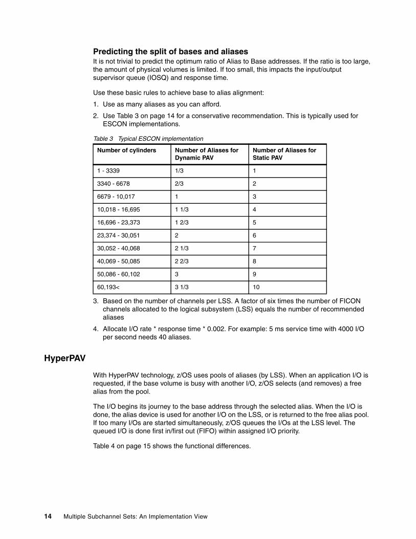
Predicting the split of bases and aliasesIt is not trivial to predict the optimum ratio of Alias to Base addresses. If the ratio is too large, the amount of physical volumes is limited. If too small, this impacts the input/output supervisor queue (IOSQ) and response time.
Use these basic rules to achieve base to alias alignment:
1. Use as many aliases as you can afford.
2. Use Table 3 on page 14 for a conservative recommendation. This is typically used for ESCON implementations.
Table 3 Typical ESCON implementation
3. Based on the number of channels per LSS. A factor of six times the number of FICON channels allocated to the logical subsystem (LSS) equals the number of recommended aliases
4. Allocate I/O rate * response time * 0.002. For example: 5 ms service time with 4000 I/O per second needs 40 aliases.
HyperPAV
With HyperPAV technology, z/OS uses pools of aliases (by LSS). When an application I/O is requested, if the base volume is busy with another I/O, z/OS selects (and removes) a free alias from the pool.
The I/O begins its journey to the base address through the selected alias. When the I/O is done, the alias device is used for another I/O on the LSS, or is returned to the free alias pool. If too many I/Os are started simultaneously, z/OS queues the I/Os at the LSS level. The queued I/O is done first in/first out (FIFO) within assigned I/O priority.
Table 4 on page 15 shows the functional differences.
Number of cylinders Number of Aliases for Dynamic PAV
Number of Aliases for Static PAV
1 - 3339 1/3 1
3340 - 6678 2/3 2
6679 - 10,017 1 3
10,018 - 16,695 1 1/3 4
16,696 - 23,373 1 2/3 5
23,374 - 30,051 2 6
30,052 - 40,068 2 1/3 7
40,069 - 50,085 2 2/3 8
50,086 - 60,102 3 9
60,193< 3 1/3 10
14 Multiple Subchannel Sets: An Implementation View

Table 4 PAV versus HyperPAV functional comparison
Aliases are used independently in each sysplex z/OS image. The workload manager (WLM) is not involved in alias movement, so it does not need to collect information to manage HyperPAV aliases.
If each LPAR needs 20 aliases, then PAV uses 60 aliases for 3 LPARS.
With HyperPAV, you can service the same requirement with 20 aliases.
A simple HyperPAV analogy:
� 4 x LPARs share a DASD LSS� 20,000 I/Os per second go to the LSS� Average response time is 1 millisecond
This means that on average, there are 20 I/Os outstanding at any given time, five from each of the four LPARs. If all requests are for the same BASE device, you need four Aliases.
A total of 10 – 20 are defined to cover spikes, depending on individual comfort zones.
Attribute PAV HyperPAV
Alias to base ratio
Complex:� One alias per 9GBs, depending on
workload and I/O rates and response time requirements
� 192 PAV-aliases/64 PAV-bases with Mod 27 volume sizes
Simple: � (Peak I/O rate * average response
time * 2) (10x reduction in the number of PAV-aliases)
� 20 PAV-aliases/236 PAV-bases (10,000/sec * 1 ms * 2)
Workload Management
Sluggish:� WLM adjustments every 10
seconds when work is not meeting goals, every minute when goals met
� I/O Priority by device Multi-system overheads:� Aggregate multi-system
measurements across SYSPLEX to make correct decisions
On Demand:Instantaneous response to changing work loads and I/O skews across devices� I/O priority by LSS.No multi-system overhead:� No multi-system aggregation of
measurements needed
RMF™ Number of PAV-aliases bound to a base per interval
Number of times I/O could not start because a PAV-alias was not available, high water mark for PAV-aliases in use for LSS
Improved Efficiency
� Alias used for specific base� PAV-aliases bound to the same
base across all operating system images
� Interlocked� Device-state-change interrupt
required in order to insure multi-system coordination of dynamic PAV-aliases
� Limited parallelism
Alias used for any base, any time on any system:� Each operating system image uses
PAV-alias for a different base at the same time, multiplier for the amount of effective number of aliases
No interlock required:� Improved parallelism for
overcoming the speed of light penalty for replication at distance
VSCR PAV-aliases reside in 31 bit storage only
10 x reduction in PAV-aliases UCBs and device related data structures
Multiple Subchannel Sets: An Implementation View 15

HyperPAV prerequisites
The HyperPAV capability is available with Version 2 of IBM DS8000 storage subsystems. Software levels of z/OS 1.6 and above is necessary with relevant maintenance from the HyperPAV subset of the preventive service planning (PSP) bucket:
http://www14.software.ibm.com/webapp/set2/psp/srchBroker
PAV analysis tool
Use the PAV analysis tool to gauge a better understanding of your workload profile and achieve a more precise split. This tool displays PAV alias usage in a 3-D graphical representation. The tool is available from the following URL:
http://www.ibm.com/servers/eserver/zseries/zos/unix/bpxa1ty2.html
16 Multiple Subchannel Sets: An Implementation View

The person that wrote this IBM Redpaper
Iain Neville is a Certified Consulting IT Specialist with IBM United Kingdom. He has 18 years of experience in System z technical support and consultancy. His areas of expertise include Parallel Sysplex®, z/OS, FICON, STP, and System z high availability solutions. Iain’s responsibilities include pre-sales System z technical consultancy that supports numerous large financial institutions across the UK.
Thanks to the following people for their contributions to this project:
Friedrich BeichterHCD/HCM DevelopmentIBM Systems and Technology Group
Harry YudenfriendSystem z Software Design, System z I/O Strategy and ArchitectureDistinguished Engineer, IBM Systems and Technology Group
Charles ShapleyI/O Configuration Planning and DesignIBM Systems and Technology Group
Bill WhiteSenior Networking and Connectivity SpecialistIBM International Technical Support Organization
Multiple Subchannel Sets: An Implementation View 17

18 Multiple Subchannel Sets: An Implementation View

Notices
This information was developed for products and services offered in the U.S.A.
IBM may not offer the products, services, or features discussed in this document in other countries. Consult your local IBM representative for information on the products and services currently available in your area. Any reference to an IBM product, program, or service is not intended to state or imply that only that IBM product, program, or service may be used. Any functionally equivalent product, program, or service that does not infringe any IBM intellectual property right may be used instead. However, it is the user's responsibility to evaluate and verify the operation of any non-IBM product, program, or service.
IBM may have patents or pending patent applications covering subject matter described in this document. The furnishing of this document does not give you any license to these patents. You can send license inquiries, in writing, to: IBM Director of Licensing, IBM Corporation, North Castle Drive, Armonk, NY 10504-1785 U.S.A.
The following paragraph does not apply to the United Kingdom or any other country where such provisions are inconsistent with local law: INTERNATIONAL BUSINESS MACHINES CORPORATION PROVIDES THIS PUBLICATION "AS IS" WITHOUT WARRANTY OF ANY KIND, EITHER EXPRESS OR IMPLIED, INCLUDING, BUT NOT LIMITED TO, THE IMPLIED WARRANTIES OF NON-INFRINGEMENT, MERCHANTABILITY OR FITNESS FOR A PARTICULAR PURPOSE. Some states do not allow disclaimer of express or implied warranties in certain transactions, therefore, this statement may not apply to you.
This information could include technical inaccuracies or typographical errors. Changes are periodically made to the information herein; these changes will be incorporated in new editions of the publication. IBM may make improvements and/or changes in the product(s) and/or the program(s) described in this publication at any time without notice.
Any references in this information to non-IBM Web sites are provided for convenience only and do not in any manner serve as an endorsement of those Web sites. The materials at those Web sites are not part of the materials for this IBM product and use of those Web sites is at your own risk.
IBM may use or distribute any of the information you supply in any way it believes appropriate without incurring any obligation to you.
Information concerning non-IBM products was obtained from the suppliers of those products, their published announcements or other publicly available sources. IBM has not tested those products and cannot confirm the accuracy of performance, compatibility or any other claims related to non-IBM products. Questions on the capabilities of non-IBM products should be addressed to the suppliers of those products.
This information contains examples of data and reports used in daily business operations. To illustrate them as completely as possible, the examples include the names of individuals, companies, brands, and products. All of these names are fictitious and any similarity to the names and addresses used by an actual business enterprise is entirely coincidental.
COPYRIGHT LICENSE:
This information contains sample application programs in source language, which illustrate programming techniques on various operating platforms. You may copy, modify, and distribute these sample programs in any form without payment to IBM, for the purposes of developing, using, marketing or distributing application programs conforming to the application programming interface for the operating platform for which the sample programs are written. These examples have not been thoroughly tested under all conditions. IBM, therefore, cannot guarantee or imply reliability, serviceability, or function of these programs.
© Copyright International Business Machines Corporation 2008. All rights reserved.Note to U.S. Government Users Restricted Rights -- Use, duplication or disclosure restricted by GSA ADP Schedule Contract with IBM Corp. 19

®
Redpaper™
This document REDP-4387-00 was created or updated on April 21, 2008.
Send us your comments in one of the following ways:� Use the online Contact us review Redbooks form found at:
ibm.com/redbooks� Send your comments in an email to:
[email protected]� Mail your comments to:
IBM Corporation, International Technical Support OrganizationDept. HYTD Mail Station P0992455 South RoadPoughkeepsie, NY 12601-5400 U.S.A.
Trademarks
The following terms are trademarks of the International Business Machines Corporation in the United States, other countries, or both:
Redbooks (logo) ®z/OS®z10™z9™DS6000™DS8000™
ESCON®FICON®IBM®Parallel Sysplex®RMF™System z™
System z10™System z9®System Storage™TDMF™
Other company, product, or service names may be trademarks or service marks of others.
20 Multiple Subchanel Sets: An Implementation View