![14 Stall Parallel Operation [Kompatibilitätsmodus] · PDF filePiston Effect Axial Fans (none stall-free) Stall operation likely for none stall-free fans due to piston ... Stall &](https://static.fdocuments.in/doc/165x107/5a9dccd97f8b9abd0a8d46cf/14-stall-parallel-operation-kompatibilittsmodus-effect-axial-fans-none-stall-free.jpg)
MULTIPLE SPIKE STALL CELLS IN LOW SPEED AXIAL …
11
JOURNAL OF THEORETICAL AND APPLIED MECHANICS 53, 1, pp. 47-57, Warsaw 2015 DOI: 10.15632/jtam-pl.53.1.47 MULTIPLE SPIKE STALL CELLS IN LOW SPEED AXIAL COMPRESSOR ROTOR BLADE ROW Reza Taghavi-Zenouz School of Mechanical Engineering, Iran University of Science and Technology, Tehran, Iran e-mail: [email protected] Sarallah Abbasi School of Mechanical Engineering, Arak University of Technology, Arak, Iran e-mail: s [email protected] Inception and development of multiple stall cells of short length scales are numerically investigated in an axial compressor rotor blade row. The method of investigation is based on time accurate three-dimensional full annulus simulations. Time dependent flow structure results revealed that there are two criteria responsible for inception of a special kind of stall, introduced as spike stall in the literature. These criteria are defined as leading edge spillage and trailing edge backflow, which occur at specific mass flow rates near to stall conditions. The numerical results revealed that once the spike stall cells appear, they cover roughly two blade passages in the circumferential direction and cover about 25% of the blade height. By further revolution of the blade row, the number of cells tends to increase. For the present case study, the number of stall cells increased to three after 8.5 rotor revolutions from the moment of the initial spike stall occurrence. Even at this moment, both of the above mentioned criteria for the spike stall inception have been observed within the blades passages. These events caused the inlet relative flow angle to the blade rows, and therefore the flow incidence angle and consequent blockage to the main flow, to increase. The tip leakage flow frequency spectrum has been studied through surveying instantaneous static pressure signals imposed on pressure side of the blades and also on the casing walls. These latter results showed that any further revolving of the rotor blade row, exceeding 8.5 revolutions, causes the spike stall to disturb the flow structure significantly. Keywords: axial compressor, spike stall inception, tip leakage flow, frequency spectrum 1. Introduction Rotating stall is known as one of the critical unsteady flow phenomena in dynamic compressors. This phenomenon, as a result of separation of flow from the blade surfaces, moves along the blade row in the circumferential direction. These separated circulatory flows, known as the stall cells, can produce blockages to the main flow within the blade passages. The rotating stall also changes pressure distributions on the blade surfaces in a periodic manner. Therefore, it would be responsible for noise generation and excitation of blade vibrations in different modes. The consequent unsteady forces may cause the compressor blades to be subjected to fatigue and fracture phenomena. So far, rotating stall inception and the consequent unsteady flow structure in axial compres- sors have been of the interests of many researchers. It has been one of the most challenging topics in the history of gas turbines. Two types of rotating disturbances, accompanied by the stall inception in axial compressors are recognized and introduced as “modal” and “spike” modes (Day, 1993; Garnier et al., 1991). These stall precursors in low and high-speed axial compressors
Transcript of MULTIPLE SPIKE STALL CELLS IN LOW SPEED AXIAL …

JOURNAL OF THEORETICAL
AND APPLIED MECHANICS
53, 1, pp. 47-57, Warsaw 2015DOI: 10.15632/jtam-pl.53.1.47
MULTIPLE SPIKE STALL CELLS IN LOW SPEED AXIAL
COMPRESSOR ROTOR BLADE ROW
Reza Taghavi-Zenouz
School of Mechanical Engineering, Iran University of Science and Technology, Tehran, Iran
e-mail: [email protected]
Sarallah Abbasi
School of Mechanical Engineering, Arak University of Technology, Arak, Iran
e-mail: s [email protected]
Inception and development of multiple stall cells of short length scales are numericallyinvestigated in an axial compressor rotor blade row. The method of investigation is basedon time accurate three-dimensional full annulus simulations. Time dependent flow structureresults revealed that there are two criteria responsible for inception of a special kind ofstall, introduced as spike stall in the literature. These criteria are defined as leading edgespillage and trailing edge backflow, which occur at specific mass flow rates near to stallconditions. The numerical results revealed that once the spike stall cells appear, they coverroughly two blade passages in the circumferential direction and cover about 25% of the bladeheight. By further revolution of the blade row, the number of cells tends to increase. Forthe present case study, the number of stall cells increased to three after 8.5 rotor revolutionsfrom the moment of the initial spike stall occurrence. Even at this moment, both of theabove mentioned criteria for the spike stall inception have been observed within the bladespassages. These events caused the inlet relative flow angle to the blade rows, and therefore theflow incidence angle and consequent blockage to the main flow, to increase. The tip leakageflow frequency spectrum has been studied through surveying instantaneous static pressuresignals imposed on pressure side of the blades and also on the casing walls. These latterresults showed that any further revolving of the rotor blade row, exceeding 8.5 revolutions,causes the spike stall to disturb the flow structure significantly.
Keywords: axial compressor, spike stall inception, tip leakage flow, frequency spectrum
1. Introduction
Rotating stall is known as one of the critical unsteady flow phenomena in dynamic compressors.This phenomenon, as a result of separation of flow from the blade surfaces, moves along theblade row in the circumferential direction. These separated circulatory flows, known as the stallcells, can produce blockages to the main flow within the blade passages. The rotating stall alsochanges pressure distributions on the blade surfaces in a periodic manner. Therefore, it wouldbe responsible for noise generation and excitation of blade vibrations in different modes. Theconsequent unsteady forces may cause the compressor blades to be subjected to fatigue andfracture phenomena.
So far, rotating stall inception and the consequent unsteady flow structure in axial compres-sors have been of the interests of many researchers. It has been one of the most challengingtopics in the history of gas turbines. Two types of rotating disturbances, accompanied by thestall inception in axial compressors are recognized and introduced as “modal” and “spike” modes(Day, 1993; Garnier et al., 1991). These stall precursors in low and high-speed axial compressors

48 R. Taghavi-Zenouz, S. Abbasi
have been extensively and continuously studied since the early 1990s. Results of these investi-gations have been used by designers for a proper control of flow instabilities within the axialcompressors.
The modal mode, generally referred to as “modal wave” or “long-wave length” inception,has been predicted by the compression system stability model of Moore and Greitzer (1986).This unsteady mode has been observed and reported by some researchers in various compressors(Day, 1993; Garnier et al., 1991). These disturbances rotate within the compressor annulus inthe direction of the rotor rotation (when viewed from the stationary frame of reference). Manystudies have shown that the modal stall can be described with no need to examination of flowdetails within the passage. The model introduced by Moore and Greitzer (1986) offers usefulinformation about the commencement of flow instabilities such as rotating stalls and surge.Spakovszky (2001) also presented some information about the flow stability of different modes inaxial compressors. However, the main shortcome of the most models, which have been presentedso far, is their failure in reliable prediction of the surge line. In fact, single/two dimensionsmodels which are presented by these researchers are not able to provide accurate information ofthese inherent complex three-dimensional flow instabilities.
Axial compressors may exhibit a short length-scale stall (i.e., spike stall) inception. Thisphenomenon, which is less understood so far, was first described by Day (1993). It is characterizedby appearance of a disturbance or “spike” with two to three blade pitches width at the rotorblades tip. Along with the advances of the computational fluid dynamics techniques, some recentnumerical investigations reveal the causal links between the blade tip clearance features and theonset of the rotating stall. Hoying et al. (1999) suggested that the spike type of the rotatingdisturbance might be explained by the behavior of the tip leakage vortex moving upstream therotor blades row as the incidence angle increases. Hah et al. (2004) explained the relation betweenthe tip leakage vortex and the rotating disturbance via unsteady three-dimensional numericalsimulation for a low speed axial compressor. Vo et al. (2008) confirmed that the presence oftransient tip clearance backflow at the trailing edge and spillage of the leading edge flow in thetip region are two criteria for the spike stall inception. Afterward, Deppe et al. (2008) surveyedthe criteria introduced by Vo et al. (2008) through their experimental studies and obtained goodconsistency.
Other unsteady flow phenomena have also been recognized at the near-stall conditions thro-ugh experimental and numerical investigations by some researchers. One type of the tip leakageflow unsteadiness in axial compressors was reported by Mailich et al. (2001) as rotating insta-bility. They realized that at some specified operating conditions the tip leakage vortex movesfrom one blade to another. This phenomenon has been studied in both the low and high speedcompressors. Marz et al. (2001) ascribed this phenomenon to existence of the induced vortexwhich rotates at about 50% blade passing frequency. Hah et al. (2006) surveyed the occurren-ce of this phenomenon at high speed compressors experimentally and numerically, respectively.They showed that this unsteadiness originates from interaction of the induced vortex flow andshock wave formed at the blade leading edge. They concluded that the breakdown of the tipleakage vortex occurs at the near-stall condition, and not only it results in unsteadiness, butalso produces a large reversed flow and blockage in the rotor tip region. Furukawa et al. (1999,2000) numerically presented consequences of the tip leakage vortex breakdown which result inunsteadiness in axial compressors.
Although the above-mentioned unsteady flow phenomena are related to the blade tip leakagevortex, details of the flow field especially the process of inception and development of the spikestall cells are still under question. In the present research work, development of multiple spikestall cells with short-length-scale is investigated in an axial compressor rotor blade row, basedon the full annulus numerical simulation.

Multiple spike stall cells in low speed axial compressor rotor blade row 49
2. Model specifications and numerical procedure
The model used in the present investigation is a low speed isolated axial compressor rotorblades row. This rotor has been also the subject of investigations of other researchers fromeither experimental or numerical point of views (Inoue et al., 1986; Furukawa et al., 1999). Theproposed rotor blade row is comprised of 12 blades of NACA-65 airfoil series type. Geometricspecifications of this rotor blade row are summarized as in Table 1 (Inoue et al., 1986). Therotational speed of the rotor blade row and the blade tip clearance size is 1300 rpm and 2mm,respectively.
Table 1. Geometric specifications of the model
Outer Hub to tip Tip clearance Tip chord Solidity of rotordiameter [mm] ratio [% of chord] length [mm] blades at tip
449 0.6 1.7 117.5 1
For a precise flow simulation and more accurate description of the unsteady flow structurethe whole annulus including all the blades, as shown in Fig. 1, has been modeled. A multi-blockstructured grid system has been employed for the numerical calculations. The surface meshsystem, generated on the model solid walls, is shown in the above figure. Each flow passageincludes 74 streamwise, 50 spanwise and 60 pichwise nodes. The mesh structure should be ofsuitable density distribution especially in the blade tip clearance region and near to solid wallsto be able to resolve the flow characteristics precisely. The radial space between the blade tipand the compressor casing is divided into 16 nodes. The mesh density near the walls ensuredthat the y+ values to be kept at less than 5, enabling the viscous sub-layer to be resolved,precisely. The whole grid system consisted of about 2700000 cells. Mesh independency studieshave been performed for confidence of the right results. No significant variations in the resultshave been observed by increasing the number of meshes exceeding that considered through thefinal calculations.
Fig. 1. Computational geometry and surface grid distribution
The well-known commercial flow solver of FLUENT is used for the current study. Thisadopted solver is a three-dimensional, viscous, time accurate code which utilizes a finite volumescheme for solution of the governing equations of continuity and momentum. The upwind second--order discretization scheme has been used to reduce the effect of numerical diffusion on thesolution. To solve the unsteady equations, to second order implicit scheme has been appliedfor discretization of the governing equations. The k-ω-SST turbulence model has been used toestimate the eddy viscosity. Multiple reference frames have been used in this study. As a result,it is possible to divide the compressor hub into the stationary and rotating parts with respect

50 R. Taghavi-Zenouz, S. Abbasi
to the inertial frame. The sliding interface has been used between the stationary and movingcomputational zones. Air velocity and its direction are fixed at the rotor inlet boundary in astationary coordinate frame. For the outlet boundary, the static pressure distribution along theblade span is given by means of the well-known radial equilibrium law. No-slip and adiabaticwall conditions are imposed over all the solid walls. Adapted time step is considered so shortfor capturing the flow properties, precisely. In the unsteady simulation process, the time stepis set in such a way that one blade passing to be completed in 120 steps. As a result, adoptedsampling frequency is about 31 kHz while blade passing frequency is 260Hz.
3. Performance curves
The tip clearance size of the rotor blade has been chosen as 2mm for the current analyses,equivalent to that considered by Inoue et al. (1986) for their experimental works. So, it ispossible to validate the present numerical results. This tip clearance size is equal to 1.7% of theblade tip chord length. Considering such a high tip clearance size can be helpful in a preciseidentification and a better physical interpretation of formation and development of the multiplespike stall cells.
Fig. 2. (a) Compressor blade row performance curves. (b), (c) Normalized exit velocity distributions fordesign condition; (b) axial velocity, (c) tangential velocity; cz – axial velocity, cθ – tangential velocity,r, rc, rh – radius, casing radius and hub radius, ψ – total pressure rise coefficient (∆P/(0.5ρu
2
t),
η – efficiency (Q∆P/L), ∆P – total pressure rise through the stage
The blade row performance curves, in terms of the stage loading factor and efficiency versusthe flow coefficient, have been calculated, and the final results are shown in Fig. 2a. The expe-rimental results of Inoue et al. (1986) are also superimposed in this figure which shows closeagreement. Based on the present numerical results, the stall inception occurs at a flow coefficientof 0.36. This point is highlighted in Fig. 2a. It is clear that the loading coefficient has slightlydecreased at this flow coefficient.
Spanwise distributions of the exit axial and tangential velocity components, normalized withrespect to the blade tip speed, are shown in Figs. 2b and 2c, respectively. The experimentaldata of Inoue et al. (1986) are also superimposed in these figures for comparison, which showclose agreement. Circumferential averaged values of the flow field parameters are considered inplotting the curves presented in these figures.
4. Stall cells
Unsteady analyses have been performed at different mass flow rates near to stall conditions.The numerical simulations have been executed for about 11 rotor revolutions in order to detectthe stall cells, their propagation and frequencies. Development and propagation of the stall cells

Multiple spike stall cells in low speed axial compressor rotor blade row 51
Fig. 3. Flow fields in terms of time averaged relative total pressure contours (left figures) and axialvelocity coefficient (right figures) at a 97% blade span; (a) spike stall inception, (b) 3 rotor revolutions
after spike stall commencement, (c) 8.5 rotor revolutions after spike stall commencement
are shown in Fig. 3. These flow fields are shown for three cases of inception of spike stall andthe subsequent 3 and 8 rotor revolutions. The left and right figures show the relative totalpressure coefficient and the axial velocity contours, respectively. These results can be used fordemonstration of the interface of the tip leakage flow and the main inflow. The streamlinespatterns are also superimposed in the left side figures for a better recognition of the spike stallinception. Both the mechanisms of the trailing edge back flow (TEB) and leading edge spillage(LES), as the two main criteria for the spike stall formation, are highlighted in these figures.Negative axial velocities of the right figures reveal the low-energy and reversed flow regions. Allresults are presented on a plane located at 97% of the blades span.
Generally speaking, trajectory of the incoming/tip clearance flow interface results from abalance between the momentums of the incoming flow and the tip leakage flow. The spike stalloccurs at the near stall condition, the position where can be reached through the throttlingprocess of the main flow. As the incoming mass flow rate reduces, the axial momentum of theincoming flow decreases. On the other hand, the momentum of the tip leakage flow increasesdue to the increment of the blade loading.

52 R. Taghavi-Zenouz, S. Abbasi
Flow fields of the spike stall inception, which has occurred at a specific flow rate (ϕ = 0.36),are demonstrated in Fig. 3a. As can be observed in this figure, in the case of spike stall occurrence(which has occurred at about 2.5 rotor revolutions), the trajectory of the incoming/tip clearanceflow interface is completely detached from the blades leading edges, and a forward spillage of thetip clearance flow has occurred. In addition, the streamlines show reversed flow at the trailingedge plane. Therefore, two features of the flow which are responsible for stall inception (i.e.,leading edge spillage and trailing edge backflow) have been formed. Finally, it can be understoodthat the spike stall has occurred under the proposed flow conditions (see Fig. 3a).
As can be observed in Fig. 3b, two aforementioned criteria for the spike stall commencementhave occurred in two regions after three rotor revolutions (following the moment of the spike stallcommencement). Each region is occupied by about two passages in the circumferential direction.The number of regions occupied by spike stall cells has increased to three at the instance of eightrotor revolutions after the spike stall inception (see Fig. 3c).
Referring to Fig. 3, it can clearly be recognized that in the regions where the spike stall hasoccurred the flow has reversed and caused considerable blockage to the main stream. As can beobserved in this figure, the blockage size is not the same in all the passages. By passing time,the size of the stall cells do not increase significantly in the axial direction, but their numbertends to increase.
Results of normalized flow angles with respect to the main inflow angle are shown in Fig. 4for a 97% span plane. High incidence and reversal regions can easily be detected from this figure.These latter results are consistent with those obtained by Hoying et al. (1999).
Fig. 4. Normalized flow angles at a 97% span
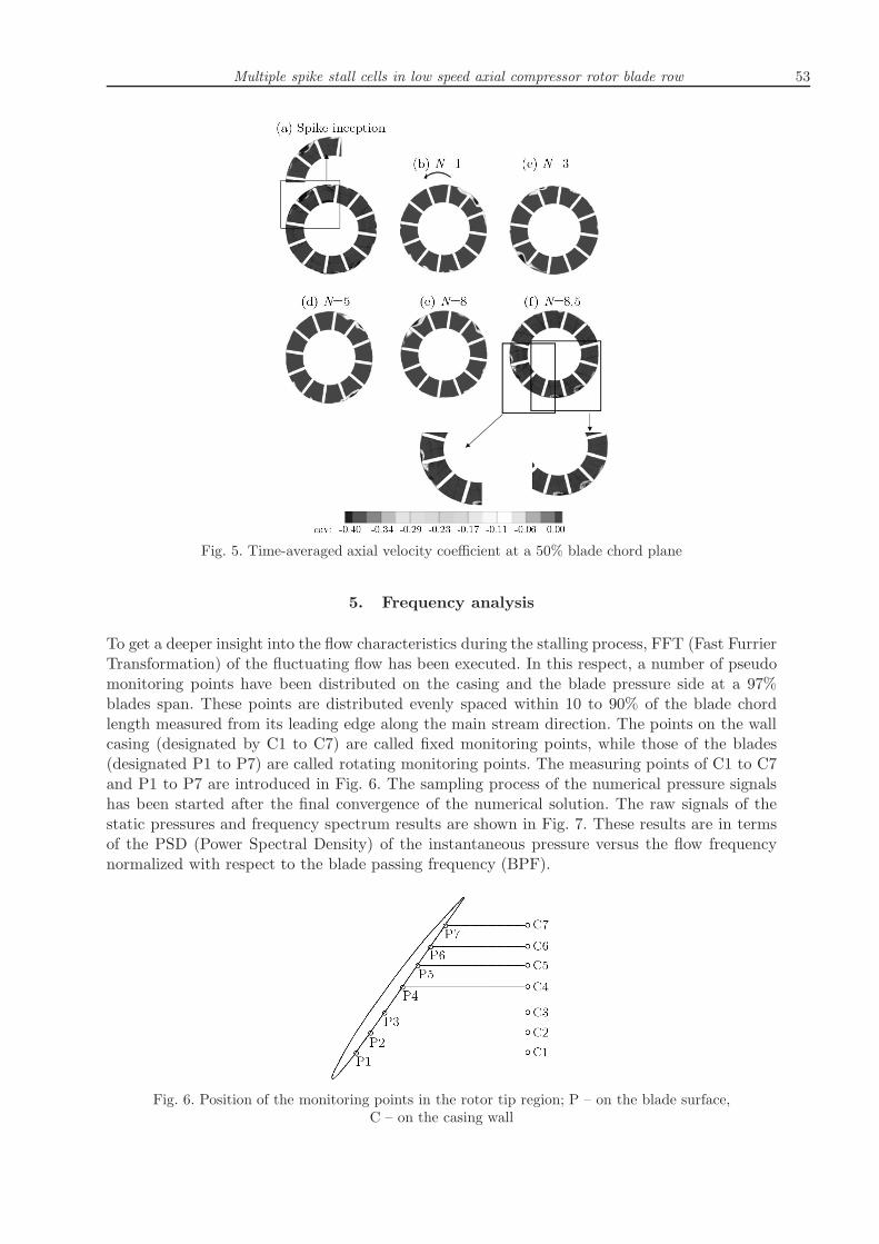
It has been recognized that the radial distribution of the axial velocity along the bladespan is an important parameter for the stall inception mode in axial compressors (Spakovszkyet al., 1999). To find out the propagation characteristics of the stall cells in the radial andcircumferential directions, the contours of negative axial velocities at a 50% axial chord crossplane are shown in Fig. 5. The results are illustrated in different times measured from the spikestall inception instant up to time of 8.5 rotor revolutions. It can be deduced that one stall celloccupies about 25% of the blades span at the stall commencement situation (see Fig. 5a). Similarto Fig. 3, by further rotation of the rotor, the number of stall cells increases without changesin their sizes. At N = 3 and 8.5, two and three dominant stall cells have appeared, respectively(see Fig. 5c and Fig. 5f). Blocked regions have formed a thin band of small stall cells near thecasing.
Based on the results presented in Fig. 5, it can be deduced that the stall cells rotate witha speed lower than the rotor blades in the relative frame system and in its opposite direction.This is the well known rotating stall phenomenon.
Multiple spike stall cells in low speed axial compressor rotor blade row 53
Fig. 5. Time-averaged axial velocity coefficient at a 50% blade chord plane
5. Frequency analysis
To get a deeper insight into the flow characteristics during the stalling process, FFT (Fast FurrierTransformation) of the fluctuating flow has been executed. In this respect, a number of pseudomonitoring points have been distributed on the casing and the blade pressure side at a 97%blades span. These points are distributed evenly spaced within 10 to 90% of the blade chordlength measured from its leading edge along the main stream direction. The points on the wallcasing (designated by C1 to C7) are called fixed monitoring points, while those of the blades(designated P1 to P7) are called rotating monitoring points. The measuring points of C1 to C7and P1 to P7 are introduced in Fig. 6. The sampling process of the numerical pressure signalshas been started after the final convergence of the numerical solution. The raw signals of thestatic pressures and frequency spectrum results are shown in Fig. 7. These results are in termsof the PSD (Power Spectral Density) of the instantaneous pressure versus the flow frequencynormalized with respect to the blade passing frequency (BPF).
Fig. 6. Position of the monitoring points in the rotor tip region; P – on the blade surface,C – on the casing wall

54 R. Taghavi-Zenouz, S. Abbasi
Fig. 7. Raw signals of instantaneous surface static pressures and their frequency spectrums in the rotorblade row tip region; (a) fixed monitoring points, (b) rotating monitoring points
Fig. 8. Raw signals of instantaneous surface static pressures and their frequency spectrum at 10% chordof each blade; (a) fixed monitoring points, (b) rotating monitoring points
It can be deduced from Fig. 7a that the dominant frequency for the fixed monitoring pointsis less than 0.2 BPF. Obviously, BPF does not appear in the FFT results while dealing withthe rotating monitoring points (see Fig. 7b). In the latter case, the dominant frequency is about0.1 BPF. Several peaks of considerable magnitudes can be observed at each chordwise position,

Multiple spike stall cells in low speed axial compressor rotor blade row 55
indicating the existence of the stall cells. This conclusion is in good agreement with the resultsof Vo et al. (2008), Zhang et al. (2005). They have shown that the periodic characteristics ofthe tip leakage flow can be recognized by occurrence of some peaks in the frequency spectrumat the near-stall condition. In addition, it is clear that the maximum amplitude of the pressuresignals has occurred at C1 (or P1) at a position near to the blade leading edge. This is due tothe existence of the tip leakage vortex flow in this region.
Frequency spectrum results at monitoring points set on 10% chord at different circumferentialangles are shown in Fig. 8. The same frequencies and amplitudes of the unsteady flow can beobserved for these monitoring points. However, a slight shift in the pressure signals can beobserved with time when moving from one monitoring point to the adjacent one.
Fig. 9. Frequency spectrums at monitoring points; left column – rotating monitoring points,right column: fixed monitoring points, (a) 0-2.5 rotor revolution, (b) 2.5-5.5 rotor revolution,
(c) 5.5-11 rotor revolution
Generally speaking, the frequency survey over a long period cannot predict that every do-minant frequency occurs within the specified time interval. As a result, the study should becarried out for a shorter time interval. Therefore, analyses have been performed at three time

56 R. Taghavi-Zenouz, S. Abbasi
intervals of N ′ = 0-2.5, N ′ = 2.5-5.5 and N ′ = 5.5-11. These results are shown in Fig. 9 forboth the fixed and rotating monitoring points. As can be depicted in this figure, the dominantfrequency before N ′ = 2.5 at a fixed monitoring point is about 0.6 BPF. Within N ′ = 2.5-5.5,the dominant frequency changes to about 0.15 BPF. In this case, the difference between theamplitudes of the tip leakage flow and BPF is reduced. Similar results have been repeated forN ′ = 5.5-11.Based on the results presented in Figs. 5 and 9, it can be concluded that the number of
stall cells and flow blockages increase in time. The occurrence and continuation of spike stallcells cause the compressor to be faced into the fully developed rotating stall. This event isaccompanied by flow unsteadiness with lower frequencies and higher amplitudes.
6. Conclusions
In this research work, a numerical study is carried out to analyze the development process ofrotating stalls in a subsonic axial compressor. The main conclusions drawn from this researchwork can be stated as follows.
• Stall inception is linked to the tip leakage flow structure. Leading edge spillage and trailingedge backflow are main criteria for spike stall formation. This type of stall cell coversroughly two blade passages in the circumferential direction and about a 25% span in theradial direction.
• By passing time, the stall cells sizes remain nearly unchanged, whilst their number incre-ases. For the present case study at 3 and 8 rotor revolutions after the commencement ofthe spike stall, two and three stall cells appear, respectively.
• In the relative frame set on the rotor blades row, the stall cells rotate in the oppositedirection with a lower speed which is called rotating stall.
• Stall cells inception due to tip leakage vortices causes not only large blockage to main flowbut also magnifies flow unsteadiness within the rotor blade passages.
• FFT of instantaneous static pressure signals showed that the tip leakage vortex frequencymay reach 0.6 BPF just before the occurrence of spike stall, and then, by further revolutionof the rotor blade row reduces to about 0.15 BPF.
• Spike stall may be eventuated to multiple stall cells which may be led to fully developedrotating stall. Consequent reversal flow may occupy most area of the flow passage whileletting the rotor blades row to operate longer.
References
1. Day I.J., 1993, Stall inception in axial flow compressors, ASME Journal of Turbomachinery, 115,1-9
2. Deppe A., Saathoff H., Stark U., 2008, Discussion: Criteria for spike initiated rotating stall,(Vo H.D., Tan C.S., Greitzer E.M., ASME Journal of Turbomachinery, 130, 011023)
3. Furukawa M., Inoue M., Saiki K., Yamada K., 1999, The role of tip leakage vortex breakdownin compressor rotor aerodynamics, ASME Journal of Turbomachinery, 121, 469-480
4. Furukawa M., Saiki K., Yamada K., Inoue M., 2000, Unsteady flow behavior due to break-down of tip leakage vortex in an axial compressor rotor at near-stall condition, ASME Paper No.2000-GT-666
5. Garnier V.H., Epstein A.H., Greitzer E.M., 1991, Rotating waves as a stall inception indi-cation in axial compressors, ASME Journal of Turbomachinery, 113, 290-301

Multiple spike stall cells in low speed axial compressor rotor blade row 57
6. Hah C., Bergner J., Schiffer H., 2006, Short length-scale rotating stall inception in a transonicaxial compressorcriteria and mechanisms, ASME Paper No. GT2006-90045
7. Hah C., Rabe D.C., Wadia A.R., 2004, Role of tip-leakage vortices and passage shock in stallinception in a swept transonic compressor rotor, ASME Paper No. GT2004-53867
8. Hoying D.A., Tan C.S., Vo H.D., 1999, Role of blade passage flow structures in axial compressorrotating stall inception, ASME Journal of Turbomachinery, 121, 735-742
9. Inoue M., Kuroumaru M., Fukuhara M., 1986, Behavior of tip leakage flow behind an axialcompressor rotor, ASME of Engineering for Gas Turbine and Power, 108, 7-14
10. Mailach R., Lehmann I., Vogeler K., 2001, Rotating instabilities in an axial compressororiginating from the fluctuating blade tip vortex, ASME Journal of Turbomachinery, 123, 453-463
11. Marz J., Hah C., Neise W., 2001, An experimental and numerical investigation into the me-chanisms of rotating instability, ASME Paper No. GT-0536
12. Moore F.K., Greitzer E.M.A., 1986, Theory of post-stall transients in axial compression sys-tems, Part I –Development of equations. Part II – Applications, Journal of Engineering for GasTurbines and Power, 108, 231-239
13. Spakovszky Z., 2001, Application of Axial and Radial Compressor Dynamic System Modeling,PhD Thesis, Massachusetts Institute of Technology, U.S.A.
14. Spakovszky Z.S., Weigl H.J., Paduano J.D., Van Schalkwyk C.M., Suder K.L., Bri-ght M.M., 1999, Rotating stall control in a high-speed stage with inlet distortion, part i: radialdistortion, ASME Journal of Turbomachinery, 121, 510-516
15. Tryfonidids M., Etchevers O., Paduano J., Epstein A., Hendricks G.J., 1995, Prestallbehavior of several high-speed compressors, Journal of of Turbomachinery, 117, 62-80
16. Vo H.D., Tan C.H., Greitzer E.M., 2008, Criteria for spike initiated rotating stall, ASMEJournal of Turbomachinery, 130, 011023
17. Zhang H., Deng X., Chen J., et al., 2005, Unsteady tip clearance flow in an isolated axialcompressor rotor, Journal of Thermal Science, 114, 211-219
Manuscript received February 25, 2014; accepted for print July 11, 2014