MULTIPLE - MODULAR MANUAL - Burnham Commercial · MULTIPLE - MODULAR MANUAL ... — 2 Water Piping...
68
846022-7/0 Price - $5.00 Commercial Boilers www.burnhamcommercialcastiron.com MULTIPLE - MODULAR MANUAL FOR GAS - FIRED BOILER SERIES 8H SIZES 5 THRU 10
Transcript of MULTIPLE - MODULAR MANUAL - Burnham Commercial · MULTIPLE - MODULAR MANUAL ... — 2 Water Piping...
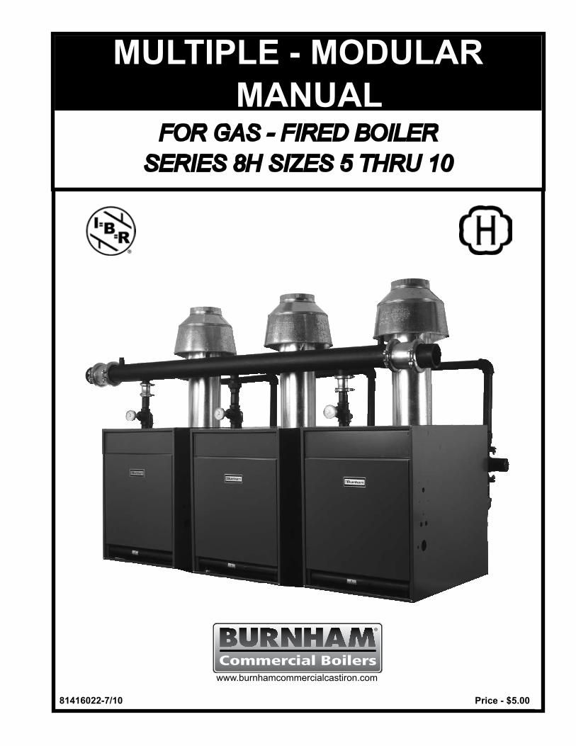
�8�4�6022-7/�0 Price - $5.00
Commercial Boilerswww.burnhamcommercialcastiron.com
MULTIPLE - MODULARMANUAL
FOR GAS - FIRED BOILERSERIES 8H SIZES 5 THRU 10
2
SECTION �.0 COMBUSTION, VENTILATION, VENT SYSTEMS 4
Fig.1—1 CompleteCombustionofNaturalGas.........................................6—2 ConfinedSpace,VentilationFromInsideBuilding.......................7—3 ConfinedSpace,VentilationFromOutdoors...............................7—4 UnconfinedSpace,VentilationFromOutdoors...........................8—5 ConstantDiameterManifoldVent................................................9—6 GraduatedDiameterManifoldVent...........................................10—7 IndividualVents.........................................................................11
SECTION 2.0 VENT DESIGN..............................................................................12
Fig.2—1 Inputvs.GrossOutputvs.NetRating.......................................14—2 RecommendedNumberofModules..........................................15—3 InputandDimensionalData......................................................16—4 TaperedManifoldVent...............................................................17—5 ConstantDiameterManifoldVent..............................................17—6 DualTakeoffConstantDiameterManifoldVent.........................18—7 DualTakeoffTaperedManifoldVent..........................................18—8,9 ConstantDiameterVent,Back-to-Back.....................................19—10 MinimumInstallationClearances...............................................20—11 FreeAreaofVentilationOpenings.............................................20—12 IndividualVentTable..................................................................21—13 CommonVentTable......................................................... 22&23—14 VentConnectorTable................................................................24—15 VentDiametervs.ChimneyArea...............................................25—16 AreaofMasonryFlueTiles........................................................26
SECTION 3.0 WATER PIPING.............................................................................27
Fig.3—1 WaterPipingforParallelPumping.............................................34—2 WaterPipingforPrimary-SecondaryPumping..........................35—3 RecommendedManifoldPiping.................................................36—4 ModuleWaterFlowData...........................................................37—5 Frictionvs.WaterFlow—IronPipe..........................................38—6 Frictionvs.WaterFlow—CopperPipe.....................................39—7 EquivalentLengthofPipefor90°Elbows.................................39—8 VolumeofWaterinPipe............................................................40—9 CompressionTankSelectionTable............................................40—10 CorrectionFactorforCompressionTankSelection...................41
LIST OF FIGURES PAGE
3
SECTION 3.0 WATER PIPING (continued)
Fig.3—11 NetExpansionFactorsforWater...............................................41—12 AcceptanceFactorsforDiaphragmTypeTanks........................42—13 ModuleData-WaterSide...........................................................42—14 WaterPipingforServiceWaterHeater......................................43—15 ServiceHotWaterDemand,FixtureUnits.................................44—16 ServiceHotWaterFlowRate....................................................44—17 SizingFactorsforCombinationHeating/ServiceWater.............45 SECTION 4.0 GAS PIPING.................................................................................. 46
Fig.4—1,2 RecommendedGasSupplyPiping................................... 49&50—3 GasPipeSizingTable...............................................................51—4 EquivalentLengthofFitting&Valves—GasPipe....................51—5 MaximumCapacityofPipe........................................................52—6 CorrectionFactorsforSpecificGravity......................................52—7 SupportofPiping.......................................................................53—8 MoistureandDirtTrap...............................................................53
SECTION 5.0 CONTROLS.................................................................................. 54
Fig.5—1 Tekmar261,Two-Stage,EI,forParallelPiping.........................55—2 Tekmar261,Two-Stage,EI,forPrimarySecondaryPiping......56—3 Tekmar263,Two-Stage,EI,forParallelPiping.........................57—4 Tekmar263,Two-Stage,EI,forPrimarySecondaryPiping......58—5 Tekmar274,Two-Stage,EI,forParallelPiping.........................59—6 Tekmar274,Two-Stage,EI,forPrimarySecondaryPiping......60—7 Tekmar268,Two-Stage,EI,forParallelPiping.........................61—8 Tekmar268,Two-Stage,EI,forPrimarySecondaryPiping......62
SECTION 6.0 START-UP AND SERVICE............................................................ 63
CAUTIONSeries 8H Boilers are NOT suitable for direct installation on combustible flooring.Refer to the 8H Installation, Operating and Service Instructions (Part Number 81416021) for Installation Instructions for Floor Shields that are available and required for combustible floor installations.
LIST OF FIGURES (continued) PAGE
4
1.1 INTRODUCTION–Thebasicprinciplesofcombustionor burning of a gaseous fuel should be reviewed briefly in order for the reader to appreciate the necessity of: (1) providing adequate ventilationfor replacement ofair consumedduring the combustionprocess and thereplacement of air carried out with the products ofcombustion, and (2) providing a properly designed vent system that will effectively convey the gases produced during theburningprocess to theoutsideatmospherealong with any air diluting the flue gases.
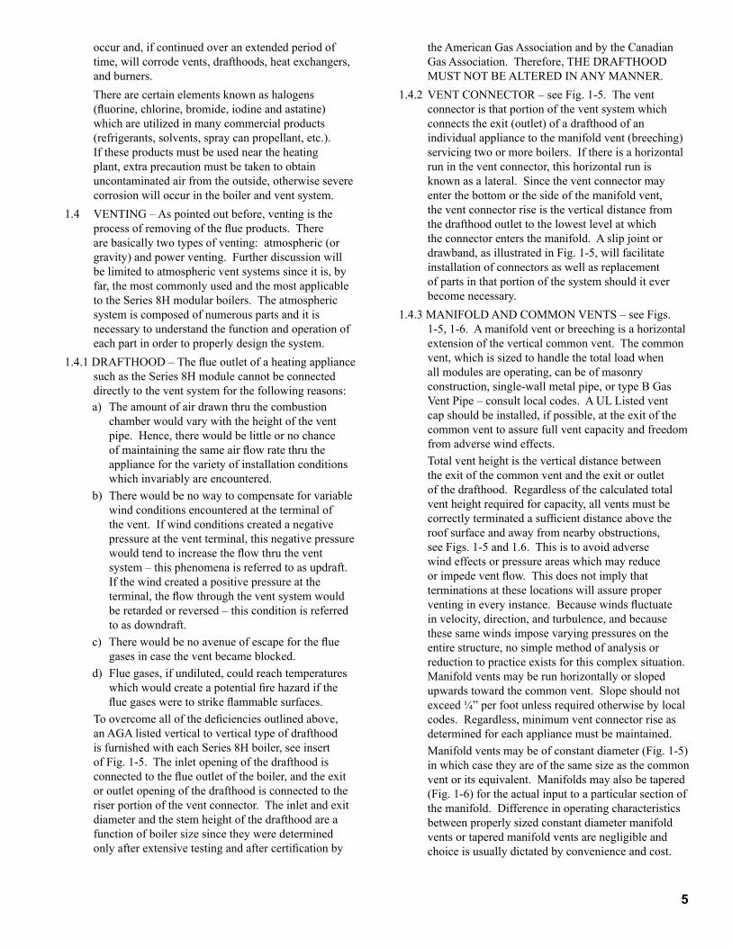
1.2 COMBUSTION–Inorderforcombustionorburningto take place three things are needed:1) Fuel-inthiscase,naturalgasorpropane.2) Oxygen-oxygen is obtained from the air which is
approximately 20% oxygen and approximately 80% nitrogen.Nitrogenisinertandwillnotburn.
3) Heat-gaswillnoturnuntilitstemperatureisraisedto its ignition point, approximately 1100-1200°F. A gas burning pilot (open flame) or electrical means (spark) is used for the initial ignition after whichthe flame itself provides the heat needed to sustain combustion.
If any of the three are taken away, combustion cannot takeplace.
Because the mixing of air and fuel is not 100% complete, more air than is actually needed called excess air must besuppliedtotheapplianceinorderforburningtobecomplete.ThisisshowninFigure1-1.
If the supply of fresh air is inadequate or is not contin-ually replenished as it is used up, carbon monoxide (CO) and Hydrogen (H2)aswellastheproductsofcombustionshown in Fig. 1-1 may be produced. This is undesirable sincecarbonmonoxideistoxicandsome-timeslethaleveninsmallquantities.
In addition to the fresh air required for combustion,fresh air is also required to dilute the flue products so that the resultant flue gas temperature is reduced to what isconsideredasafelevel.Thus,atotalof16cu.Ft.ofair may be required for each cu. ft. of gas burned, 12.5 cu. ft. for the combustion process and 3.5 cu. ft. for the dilutionprocess.
1.3 VENTILATION – Fresh air requirements for the heating plant will vary with the space in which the plant is located asdescribedandillustratedinsucceedingparagraphs.Referencetofreeareaofairinletsismadeinthetextsincelouvers,grilles,orscreensaresometimesusedatorintheinletandthesehaveablockingeffect.Thismustbe taken into consideration in order to obtain properquantitiesoffreshair.Ifthefreeareasofthesedevicesare not known, it may be assumed that wood louvers will have 20-25% free area and metal louvers and grilles will have 60-75% free area.
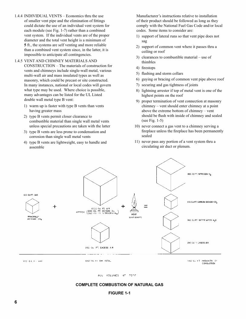
For installation in boiler rooms with ventilation airprovided from inside of building having adequateinfiltration from outdoors, each opening shall have a free area of not less than one (1) square inch per 1000 Btuh ofthetotalinputratingoftheheatingplantandotherfuelburningapplianceintheboilerroom.SeeFigure1-2.
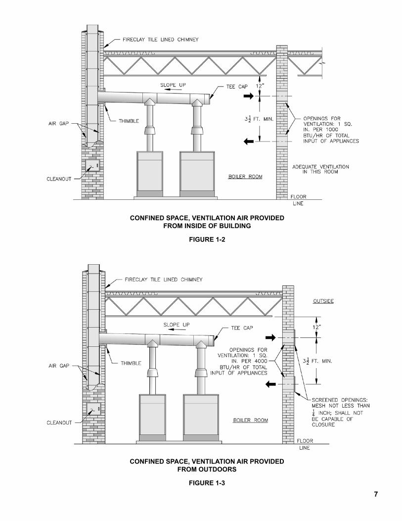
For installation in boiler rooms with ventilation airprovided directly from outdoors, each opening shall have a free area of not less than one (1) square inch per 4000 Btuhofthetotalinputratingoftheheatingunitandotherfuelburningapplianceintheboilerroom.Eachopeningshouldbeequippedwithascreencoveringwhosemeshshouldnotbelessthan¼inchandeachopeningshouldbe constructed so that they cannot be closed. See Figure 1-3.
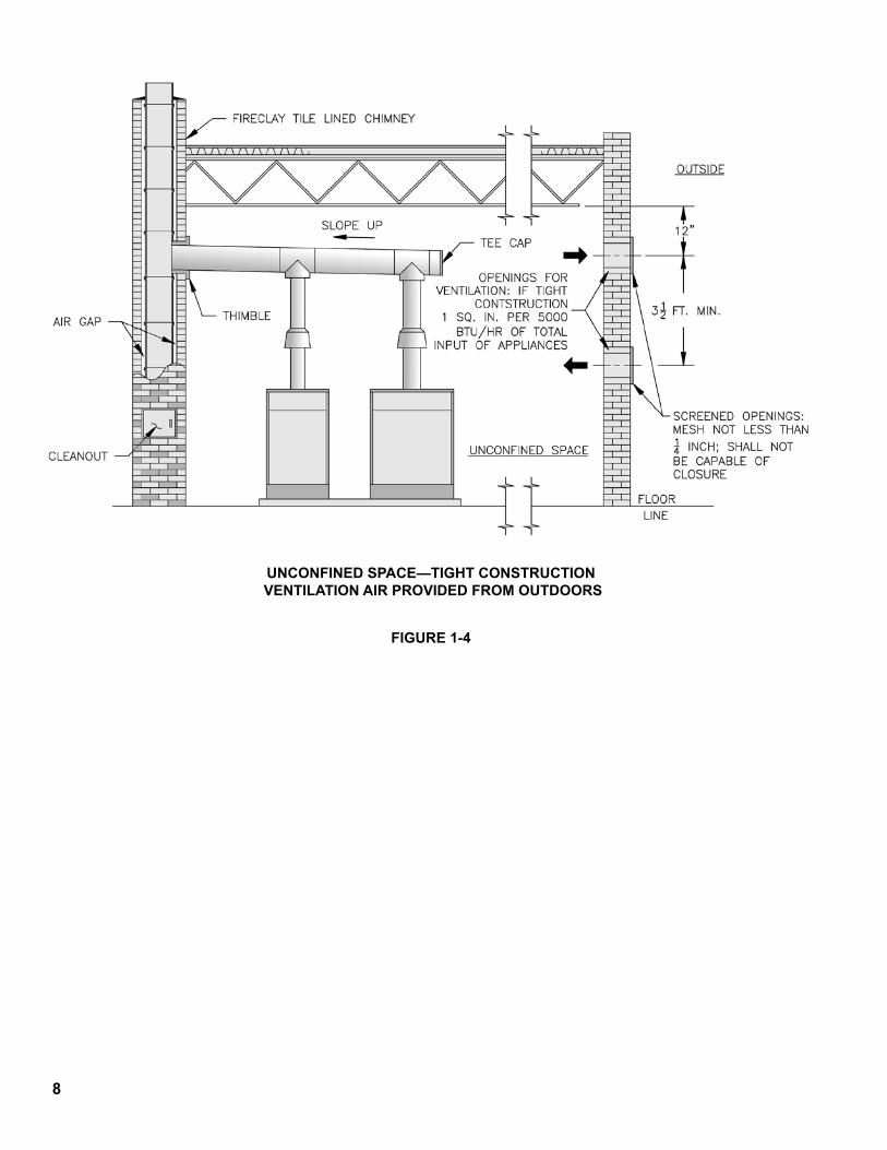
Normally, if the boiler is installed in an unconfined space, an adequate amount of ventilation air will be supplied by natural infiltration. If however, the unconfined space is of unusually tight construction, air from outdoors will be needed. A permanent opening or openings with a total free area of not less than one (1) square inch per 5000 Btuhofthetotalinputratingoftheheatingplantandother fuel burning appliances in the unconfined space is necessary. If ducts (minimum rectangular area of 3 square inches) are used, they must be the same cross-sectionalareaasthefreeareaoftheopeningtowhichthey connect. Screening to cover the openings to the outside should not be smaller than ¼ inch mesh andeach opening should be constructed so that they cannot beclosed.SeeFigure1-4.
CAUTIONS The importance of adequate and proper ventilation
cannotbeoveremphasized.Itmustalsobeunderstoodthat venting and ventilation must always be considered together. They are both part of the same system and mustbalanceeachother.
Ifexhaustfansareutilizedsuchasformake-upair,themake-upairshouldnotbedrawnfromthesamespacethatisthesourceofcombustionairfortheheatingplantunless adequate provisions are made to supply additional outside air so that the space surrounding the heatingunitisnotunderanegativepressures(lessthanoutdoorpressure).
Blowers should not be used to forcibly provide ventilation unlesscontrolledtoapointwherestaticpressureinthespaceinwhichtheheatingplantislocatedisequaltotheoutdoorpressure.
Excess pressure resulting from larger than necessary volumesoffreshairwillcauseexcessivedilutionof the flue products resulting in low flue gas temperatures.Ifloweredbelowthedewpoint,condensation of the moisture in the flue gases will
SECTION �.0 COMBUSTION,VENTILATION & VENT SYSTEMS
5
occurand,ifcontinuedoveranextendedperiodoftime,willcorrodevents,drafthoods,heatexchangers,andburners.
Therearecertainelementsknownashalogens(fluorine, chlorine, bromide, iodine and astatine) which are utilized in many commercial products (refrigerants, solvents, spray can propellant, etc.). Iftheseproductsmustbeusedneartheheatingplant,extraprecautionmustbetakentoobtainuncontaminatedairfromtheoutside,otherwiseseverecorrosion will occur in the boiler and vent system.
1.4 VENTING – As pointed out before, venting is the process of removing of the flue products. There are basically two types of venting: atmospheric (or gravity) and power venting. Further discussion will be limited to atmospheric vent systems since it is, by far, the most commonly used and the most applicable to the Series 8H modular boilers. The atmospheric system is composed of numerous parts and it is necessary to understand the function and operation of each part in order to properly design the system.
1.4.1 DRAFTHOOD – The flue outlet of a heating appliance such as the Series 8H module cannot be connected directly to the vent system for the following reasons:a) Theamountofairdrawnthruthecombustion
chamber would vary with the height of the vent pipe.Hence,therewouldbelittleornochanceof maintaining the same air flow rate thru the appliance for the variety of installation conditions which invariably are encountered.
b) There would be no way to compensate for variable windconditionsencounteredattheterminalofthevent.Ifwindconditionscreatedanegativepressureattheventterminal,thisnegativepressurewould tend to increase the flow thru the vent system – this phenomena is referred to as updraft. Ifthewindcreatedapositivepressureattheterminal, the flow through the vent system would beretardedorreversed–thisconditionisreferredtoasdowndraft.
c) There would be no avenue of escape for the flue gasesincasetheventbecameblocked.
d) Fluegases,ifundiluted,couldreachtemperatureswhich would create a potential fire hazard if the flue gases were to strike flammable surfaces.
To overcome all of the deficiencies outlined above, an AGA listed vertical to vertical type of drafthood is furnished with each Series 8H boiler, see insert of Fig. 1-5. The inlet opening of the drafthood is connected to the flue outlet of the boiler, and the exit oroutletopeningofthedrafthoodisconnectedtotheriserportionoftheventconnector.Theinletandexitdiameterandthestemheightofthedrafthoodareafunction of boiler size since they were determined only after extensive testing and after certification by
the American Gas Association and by the Canadian Gas Association. Therefore, THE DRAFTHOOD MUST NOT BE ALTERED IN ANY MANNER.
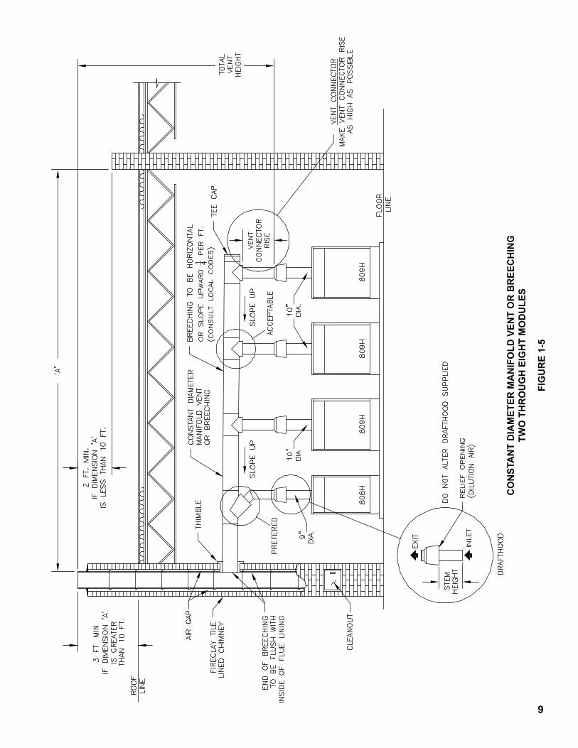
1.4.2 VENT CONNECTOR – see Fig. 1-5. The vent connector is that portion of the vent system which connectstheexit(outlet)ofadrafthoodofanindividualappliancetothemanifoldvent(breeching)servicingtwoormoreboilers.Ifthereisahorizontalrunintheventconnector,thishorizontalrunisknown as a lateral. Since the vent connector may enterthebottomorthesideofthemanifoldvent,theventconnectorriseistheverticaldistancefromthedrafthoodoutlettothelowestlevelatwhichthe connector enters the manifold. A slip joint or drawband, as illustrated in Fig. 1-5, will facilitate installationofconnectorsaswellasreplacementof parts in that portion of the system should it ever become necessary.
1.4.3 MANIFOLD AND COMMON VENTS – see Figs. 1-5, 1-6. A manifold vent or breeching is a horizontal extensionoftheverticalcommonvent.Thecommonvent,whichissizedtohandlethetotalloadwhenall modules are operating, can be of masonry construction, single-wall metal pipe, or type B Gas Vent Pipe – consult local codes. A UL Listed vent capshouldbeinstalled,ifpossible,attheexitofthecommon vent to assure full vent capacity and freedom fromadversewindeffects.
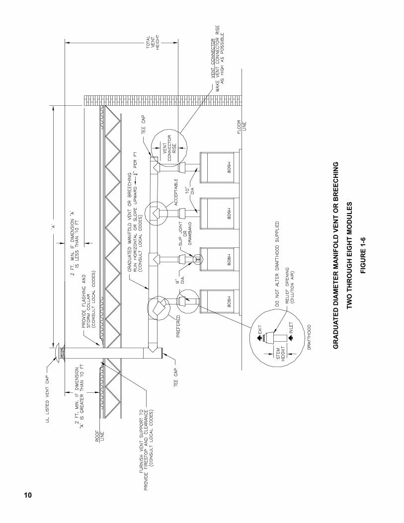
Totalventheightistheverticaldistancebetweentheexitofthecommonventandtheexitoroutletofthedrafthood.Regardlessofthecalculatedtotalvent height required for capacity, all vents must be correctly terminated a sufficient distance above the roof surface and away from nearby obstructions, see Figs. 1-5 and 1.6. This is to avoid adverse wind effects or pressure areas which may reduce or impede vent flow. This does not imply that terminationsattheselocationswillassureproperventing in every instance. Because winds fluctuate in velocity, direction, and turbulence, and because these same winds impose varying pressures on the entire structure, no simple method of analysis or reductiontopracticeexistsforthiscomplexsituation.Manifold vents may be run horizontally or sloped upwardstowardthecommonvent.Slopeshouldnotexceed ¼” per foot unless required otherwise by local codes.Regardless,minimumventconnectorriseasdeterminedforeachappliancemustbemaintained.
Manifold vents may be of constant diameter (Fig. 1-5) in which case they are of the same size as the common vent or its equivalent. Manifolds may also be tapered (Fig.1-6)fortheactualinputtoaparticularsectionofthemanifold.Differenceinoperatingcharacteristicsbetween properly sized constant diameter manifold ventsortaperedmanifoldventsarenegligibleandchoice is usually dictated by convenience and cost.
6
COMPLETE COMBUSTION OF NATURAL GAS
FIGURE �-�
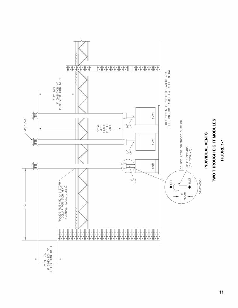
1.4.4 INDIVIDUAL VENTS – Economics thru the use of smaller vent pipe and the elimination of fittings could dictate the use of an individual vent system for each module (see Fig. 1-7) rather than a combined vent system. If the individual vents are of the proper diameterandthetotalventheightisaminimumof5 ft., the systems are self venting and more reliable than a combined vent system since, in the latter, it is impossibletoanticipateallcontingencies.
1.4.5 VENT AND CHIMNEY MATERIALS AND CONSTRUCTION–Thematerialsofconstructionforvents and chimneys include single-wall metal, various multi-wall air and mass insulated types as well as masonry, which could be precast or site constructed. In many instances, national or local codes will govern what type may be used. Where choice is possible, many advantages can be listed for the UL Listed double wall metal type B vent:1) warm up is faster with type B vents than vents
havinggreatermass2) type B vents permit closer clearance to
combustiblematerialthansinglewallmetalventsunlessspecialprecautionsaretakenwiththelatter
3) type B vents are less prone to condensation and corrosionthansinglewallmetalvents
4) type B vents are lightweight, easy to handle and assemble
Manufacturer’sinstructionsrelativetoinstallationof their product should be followed as long as they comply with the National Fuel Gas Code and/or local codes. Some items to consider are:1) supportoflateralrunssothatventpipedoesnot
sag2) supportofcommonventwhereitpassesthrua
ceilingorroof3) clearancestocombustiblematerial–useof
thimbles4) firestops5) flashing and storm collars6) guying or bracing of common vent pipe above roof7) securing and gas tightness of joints8) lightning arrester if top of metal vent is one of the
highestpointsontheroof9) proper termination of vent connection at masonry
chimney – vent should enter chimney at a point above the extreme bottom of chimney – vent should be flush with inside of chimney and sealed (see Fig. 1-5)
10) never connect a gas vent to a chimney serving a fireplace unless the fireplace has been permanently sealed
11) never pass any portion of a vent system thru a circulatingairductorplenum.
7
CONFINED SPACE, VENTILATION AIR PROVIDED FROM INSIDE OF BUILDING
FIGURE �-2
CONFINED SPACE, VENTILATION AIR PROVIDED FROM OUTDOORS
FIGURE �-3
8
UNCONFINED SPACE—TIGHT CONSTRUCTION VENTILATION AIR PROVIDED FROM OUTDOORS
FIGURE �-4
�
CO
NST
AN
T D
IAM
ETER
MA
NIF
OLD
VEN
T O
R B
REE
CH
ING
TWO
TH
RO
UG
H E
IGH
T M
OD
ULE
S
FIG
UR
E �-
5
�0
GR
AD
UAT
ED D
IAM
ETER
MA
NIF
OLD
VEN
T O
R B
REE
CH
ING
TWO
TH
RO
UG
H E
IGH
T M
OD
ULE
S
FIG
UR
E �-
6
��
IND
IVID
UA
L VE
NTS
TWO
TH
RO
UG
H E
IGH
T M
OD
ULE
S
FIG
UR
E �-
7
�2
2.1 Vents, or breeching ducts, are generally less flexible indesignlocationthanarewaterpipes,gaspipesor electrical lines. To avoid conflicts for a given location, design and layout the vents in this section beforeproceedingtoothersectionsofthismanual.
2.2 Obtainascaleddrawingoftheboilerroom.Notethefloor size, ceiling height, exterior walls, and chimney location,ifprovided.
2.3 Determine the input required to the system. It is recommended that the heating load be determined by anaccuratecalculationoftheheatlossofthestructureusing methods contained in the ASHRAE Guide. If service water is to be added capacity as described in paragraph 3.13 of this manual. The boiler capacity soobtainedisnetratingtoinput.Recordtheinputrequiredontheboilerroomdrawing.
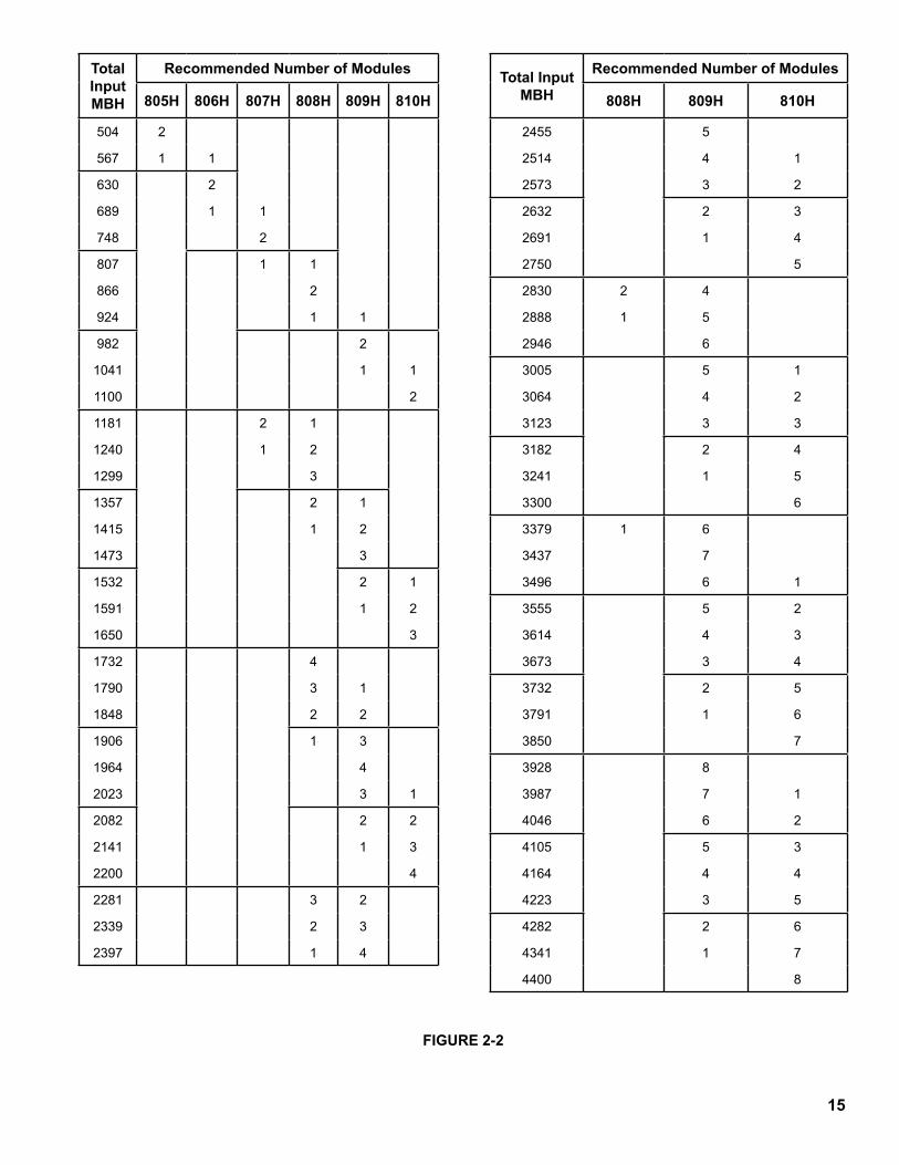
2.4 Using Figure 2-2 for the input found in 2.3 above, find thenumberofmodulesrecommended.Thosemodulecombinationsshownrepresentthebestselectionforlowest first cost. Other combinations may be selected, within the following guidelines:1) Modules using a sequencing control system, such
as Control System C, D, or TMC described in Section 5.0, should not vary by more than one size.
2) Modules using a combined vent system should not vary by more than one size.
3) Thecombinedventsizingproceduresinthissectionarebasedonamaximumofeightmodulesusing a common vent system. If it is desired to servemorethaneightmoduleswithacommonvent system, the specific requirements should be referred to the BURNHAM Application EngineeringDepartment.
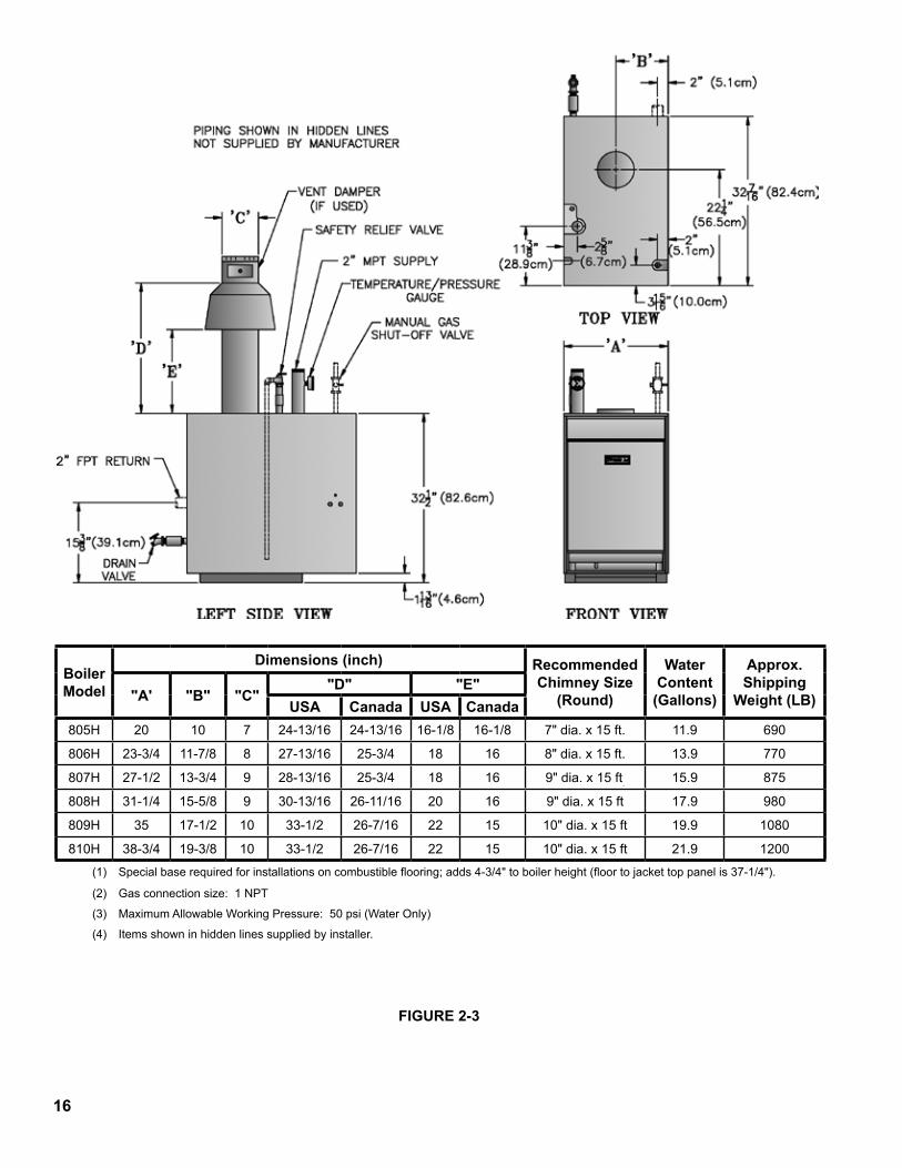
RefertoFigure2-3forindividualmoduleinputs.2.4.1Sketchontheboilerroomdrawingtheapproximate
locationofthemodules.Figures2-4thru2-9showseveral layouts that can be used depending on the size and shape of the boiler room and chimney location, ifprovided.RefertoFigure2-3fordimensionaldataon individual modules. Select the layout which best fits the boiler room. Bear in mind that for combined vent systems it is desirable to keep horizontal laterals as short as possible. On a combined vent system for which a fixed chimney is provided, it is desirable to place the first module close to the chimney.
2.4.2 If the factory fabricated water manifolds are to be used, 805H, 806H, and 807H modules should be laid out with 28½” module spacing and 808H, 809H, and 810H modules should be laid out with 40” module spacing. If an 807H and an 808H module are to be connectedtoacommonmanifold,usethelongermanifold with 40” spacing. Otherwise, any module spacing that allows at least 1 inch jacket –to-jacket spacingifacceptable,pendinglocalorstatecoderequirements that may require greater module to modulespacing.
2.4.3 Refer to Figure 2-10 for minimum clearances around modulestocombustiblematerialsandforserviceaccess. CAUTION: Local fire ordinances may be morerestrictiveandshouldbecompliedwith.
2.5 One of the serious errors made in layout of a boiler room is the failure to provide sufficient ventilation air. Insufficient ventilation air will cause incomplete combustion,poorignition,accumulationofsootinthe boiler, or the production of toxic gases. Many service calls for dirty boilers, nuisance lock outs, noisy ignition, or obnoxious odors are traceable to insufficient ventilation air. Use Figure 2-11 at the input desired to find the recommended free area of the ventilationopeningrequired.ReferencetoFigures1-2thru1-4shouldbemadeinordertounderstandthe types of installations described in the headings ofFigure2-11.Recordthefreeventilationarearequiredontheplansoftheboilerroomandsketchthe openings like those shown in figures 1-2 thru 1-4 respectively.
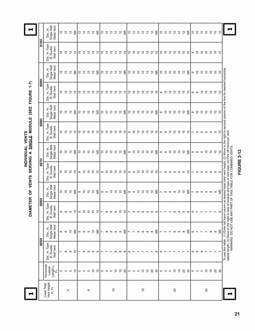
2.6 Individual vents as shown in Figure 1-7 are highly recommended if the job site conditions allow. Individual vents are particularly useful in boiler rooms havingalowceilingheight.Individualventsareeasy to design and in many cases result in the lowest installed cost. They also are the most dependable in operationandlesssusceptibletocondensationthanarecombinedvents.Tosizeindividualvents,useFigure2-12withtheventheightavailable,thelaterallength,size of module and type of vent pipe.
2.7 Combined vents will perform satisfactorily if strict designproceduresarefollowed.ReferringtoFigures2-4thru2-9,notethataconnectorriseFofatleastone foot is required. A connector rise F of three feet isdesirable.Thus,tomakethedesiredconnectorriseandhavespaceforthemanifoldvent,theminimumboiler room ceiling height must be equal to:
32½” Module Height +) DrafthoodHeight +F MinimumConnectorRise +CV ManifoldDiameter +6” Clearance = MinimumCeilingHeight Iftheminimumceilingheightaboveisnotavailable,
common vents will not perform satisfactorily and shouldnotbeused.
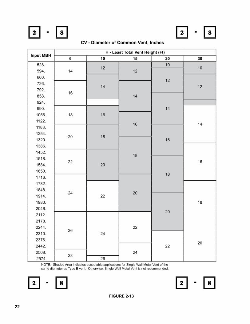
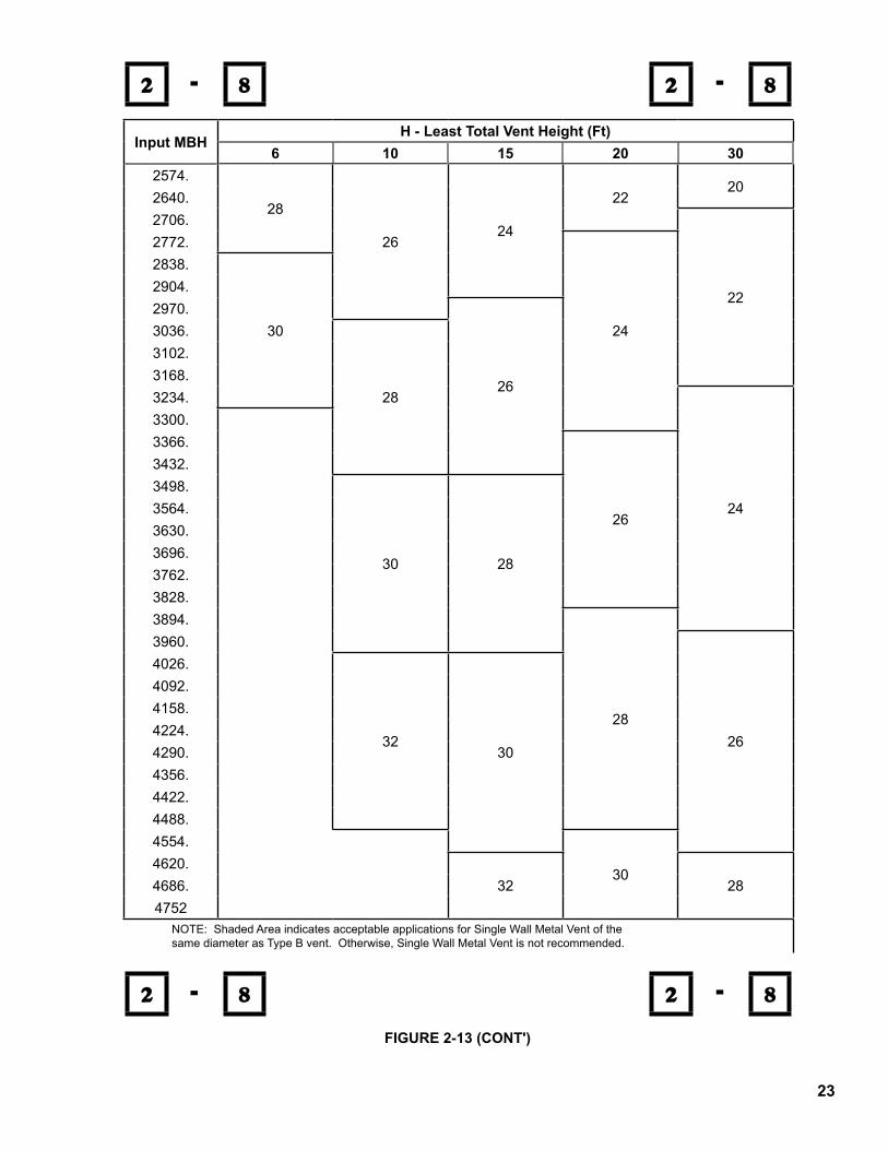
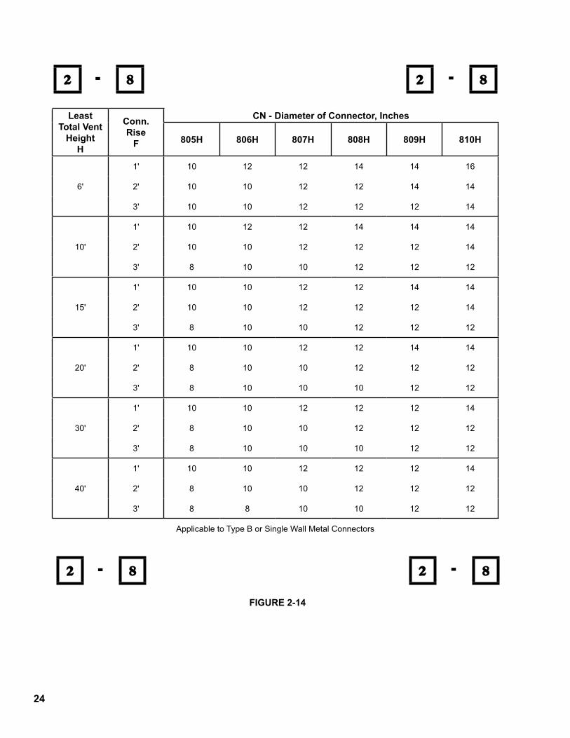
2.7.1 If the minimum ceiling height is available, proceed tosizethecommonventCVinFigure2-13.Enterthelefthandcolumnatthedesiredtotalinputandmove right to the column corresponding to your H,leasttotalventheight,andreadthediameterofthecommonvent.Ifmorethanoneelbowisused,increase CV by one pipe size for each elbow more thanone.ProceedtosizetheconnectorrisediameterCN by entering Figure 2-14 at H available and move
SECTION 2.0 VENTS
�3
righttothecolumnheadedF.OnthelineforavailableconnectorrisemoverighttotheCNcolumnsheadedby the module sizes selected in 2.4 above. Read the connectordiameter(s).Recordthesesizesontheplansoftheboilerroom.
2.7.2 If a tapered or graduated manifold vent is desired, use thesameproceduresaboveforsizingtheintermediatemanifolddiameterbutforthetotalinputofthemodules served by intermediate tapered or graduated manifoldvent.
2.7.3 Within Figure 2-12 are several entries of NR. Thismeansthatthecombinationinvolvedisnotrecommended.ThemostcommonreasonforacombinationtobedesignatedNRisthatcondensation inside the vent pipe is likely to occur. This is particularly true of single wall vent pipe. CombinationsoutsidetheshadedareainFigure2-13arealsonotrecommendedforsinglewallventpipe.Additionally, single wall vent pipe should not be used with five or more modules because the dilution from the unfired modules plus the lower surface temperatureofsinglewallpipemakescondensationand the resulting corrosion very likely.
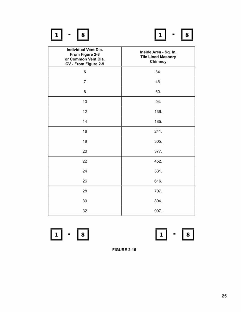
2.8 If a masonry chimney is desired, the minimum cross sectional area of the chimney is found in Figure 2-15 asafunctionoftheventdiameter.Figure2-16showsthe area of standard chimney tiles by size.
2.9 Thefollowingisanexampleoftherecommendeddesignprocedures.
Example: A 3 story apartment house needs a total boiler capacity including service water hating, of 1,849,500 Btu/Hr net rating. The boiler room is in a one story added portion of the building, of non-combustible construction, similar to Figures 1-6 or 1-7 and is 20 feet long, 10 feet wide with a clear ceiling of 12 feet. No chimney is provided. Select and size the vent system.1) RefertoFigure2-1toconvertnetratingtoinput.
Input = 1,849,500 x 1.44 = 2,663,280 Btuh = 2,663 MBH.
2) From Figure 2-2 find the closest recommended modulecombinationhavinganinputof2663MBH. It is found that an input of 2706 MBH is the closest size and is composed of four 809H and one 810H modules.
3) Sketchapproximatemodulelocationsontheboilerroomplansusingminimumclearancesrecommen-dedin2.4above.Inthiscasethereisspacetolay-out the five modules in line along one wall on 40” centers with ample service clearances, front, rear, and sides, per Figure 2-10.
4) Determinetheventilationareasrequiredfromfigure 2-11. It is a confined space but outdoor air is readily available through vents in the exterior wall. Use the equation for Confined with Outdoor Vent:
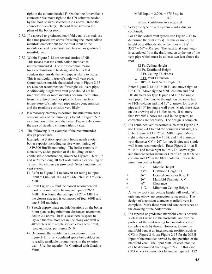
MBHInput=2,706. = 675.5 sq. in. 4.0 4.0 offreeventilationarearequired.5) Select the type of vent system – individual or
combined. For an individual vent system use Figure 2-12 to
determinetheventsize(s).Inthisexample,theheight of drafthoods above the floor = 32½” + 33½” = 66” = 5½ feet. The least total vent height iscalculatedfromthedrafthooduptothetopoftheventpipewhichmustbeatleasttwofeetabovetheroof. 12Ft.CeilingHeight - 5½ Ft. Drafthood Height + 2Ft.CeilingThickness + 2Ft.VentExtension = 10½ Ft. total Vent Height, H
Enter Figure 2-12 at H = 10 Ft. and move right to L = O Ft. Move right to 809H column and find 10” diameter for type B pipe and 10” for single wallpipe.Continuetotherightonthesamelineto 810H column and find 10” diameter for type B pipe and 10” for single wall pipe. Mark these sizes onthedrawingoftheboilerroom.Ifnomorethan two 90° elbows are used in the system, no corrections are necessary. The design is complete.
6) If a combined vent is desired such as in Figure 1-5, use Figure 2-13 to find the common vent size, CV. Enter Figure 2-13 at 2706. MBH input. Move right to the column H = 10 Ft. and find common vent diameter CV = 26” for type B pipe and single wallisnotrecommended.EnterFigure2-14atH= 10 Ft. and move right to F = 3 Ft. Move right and find connector diameter CN of 12” in the 809H column and 12” in the 810H column. Calculate minimumceilingheight.
32½” Module Height + 33½” Drafthood Height, D + 36” DesiredconnectorRise,F + 26” ManifoldDiameter,CV + 6” Clearance = 11’2” MinimumCeilingHeight A twelve foot clear ceiling height will work. With
only one elbow, no correction is necessary. The designofaconstantdiametermanifoldventiscomplete.Marktheseventandconnectorsizesonthedrawingoftheboilerroom.
7) If a tapered or graduated manifold vent is desired, suchasinFigure1-6thehorizontalandverticalportion of the vent serving five modules is also completewith6)above.However,tosizethemanifoldventatanintermediatepositionsuchasCV3inFigure2-4,useFigure2-13fortheMBHInput of the modules served by that position of the manifoldvent.TheInputMBHofeachmodulecanbedeterminedfromFigure2-3.InthiscaseCV3servestwomoduleshavinganinputof1122
�4
MBH. Enter figure 2-13 at an input of 1122 MBH. Move right to H = 10 Ft. and find CV3 =16”diameter.Markthisventdiametersizeonthedrawingoftheboilerroom.Thusagraduatedmanifoldventdesigniscomplete.Itispossiblewiththisproceduretoreducethemanifoldventsizeaftereachmodule.However,fromapracticalstandpoint, the cost of fittings may offset the lower costofsmallerventpipe.
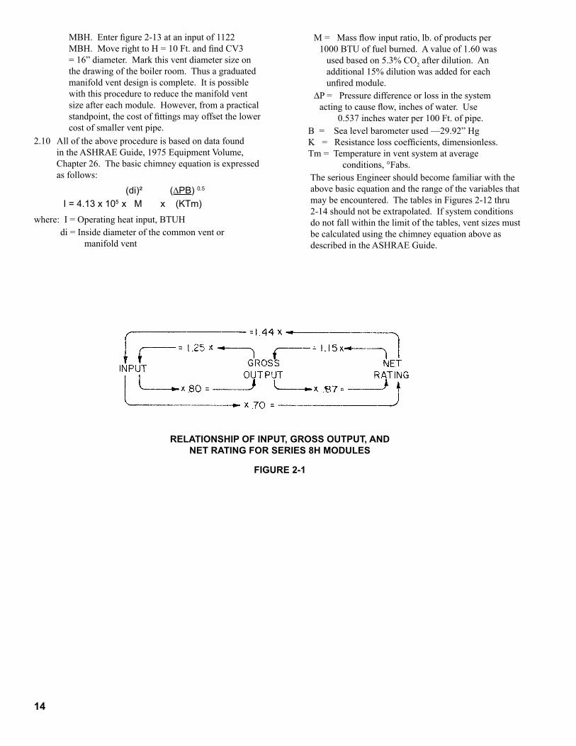
2.10 All of the above procedure is based on data found in the ASHRAE Guide, 1975 Equipment Volume, Chapter 26. The basic chimney equation is expressed as follows:
RELATIONSHIP OF INPUT, GROSS OUTPUT, AND NET RATING FOR SERIES 8H MODULES
FIGURE 2-�
where: I = Operating heat input, BTUH di=Insidediameterofthecommonventor
manifoldvent
M = Mass flow input ratio, lb. of products per 1000 BTU of fuel burned. A value of 1.60 was used based on 5.3% CO2 after dilution. An additional 15% dilution was added for each unfired module.
∆P = Pressure difference or loss in the system acting to cause flow, inches of water. Use 0.537 inches water per 100 Ft. of pipe.
B=Sealevelbarometerused—29.92”HgK = Resistance loss coefficients, dimensionless.Tm = Temperature in vent system at average
conditions, °Fabs. TheseriousEngineershouldbecomefamiliarwiththe
abovebasicequationandtherangeofthevariablesthatmay be encountered. The tables in Figures 2-12 thru 2-14 should not be extrapolated. If system conditions donotfallwithinthelimitofthetables,ventsizesmustbe calculated using the chimney equation above as described in the ASHRAE Guide.
(di)² (∆PB)0.5
I=4.13x10⁵xMx(KTm)
�5
FIGURE 2-2
Total Input MBH
Recommended Number of Modules
805H 806H 807H 808H 80�H 8�0H
504 2
567 1 1
630 2
689 1 1
748 2
807 1 1
866 2
924 1 1
982 2
1041 1 1
1100 2
1181 2 1
1240 1 2
1299 3
1357 2 1
1415 1 2
1473 3
1532 2 1
1591 1 2
1650 3
1732 4
1790 3 1
1848 2 2
1906 1 3
1964 4
2023 3 1
2082 2 2
2141 1 3
2200 4
2281 3 2
2339 2 3
2397 1 4
Total Input MBH
Recommended Number of Modules
808H 80�H 8�0H
2455 5
2514 4 1
2573 3 2
2632 2 3
2691 1 4
2750 5
2830 2 4
2888 1 5
2946 6
3005 5 1
3064 4 2
3123 3 3
3182 2 4
3241 1 5
3300 6
3379 1 6
3437 7
3496 6 1
3555 5 2
3614 4 3
3673 3 4
3732 2 5
3791 1 6
3850 7
3928 8
3987 7 1
4046 6 2
4105 5 3
4164 4 4
4223 3 5
4282 2 6
4341 1 7
4400 8
�6
FIGURE 2-3
Boiler Model
Dimensions (inch) Recommended Chimney Size
(Round)
Water Content
(Gallons)
Approx. Shipping
Weight (LB)"A' "B" "C""D" "E"
USA Canada USA Canada805H 20 10 7 24-13/16 24-13/16 16-1/8 16-1/8 7"dia.x15ft. 11.9 690
806H 23-3/4 11-7/8 8 27-13/16 25-3/4 18 16 8"dia.x15ft. 13.9 770
807H 27-1/2 13-3/4 9 28-13/16 25-3/4 18 16 9"dia.x15ft. 15.9 875
808H 31-1/4 15-5/8 9 30-13/16 26-11/16 20 16 9"dia.x15ft 17.9 980
809H 35 17-1/2 10 33-1/2 26-7/16 22 15 10"dia.x15ft 19.9 1080
810H 38-3/4 19-3/8 10 33-1/2 26-7/16 22 15 10"dia.x15ft 21.9 1200
(1) Specialbaserequiredforinstallationsoncombustibleflooring;adds4-3/4"toboilerheight(floortojackettoppanelis37-1/4").
(2) Gasconnectionsize:1NPT
(3) MaximumAllowableWorkingPressure:50psi(WaterOnly)
(4) Itemsshowninhiddenlinessuppliedbyinstaller.
�7
FIGURE 2-4
FIGURE 2-5
�8
FIGURE 2-6
FIGURE 2-7
��
FIGURE 2-8
FIGURE 2-�
20
MINIMUM INSTALLATION CLEARANCES AROUND MODULES
FIGURE 2-�0
TOTAL FREE AREA OF VENTILATION OPENINGS, SQ. IN.
FIGURE 2-��
Drafthood & Vent Connector
Top of Jacket Front Side Rear 5 6 Side-
by-Side6 Back-to-
Back6 Front-to-
Front805-806-807
ToCombustibleConstruction 16" 236" 118" 16" 16" N/A N/A N/A
RecommendedForServicing N/A 124" 124" 818" 24" 11" 26" 736"
808-80�-8�0ToCombustible
Construction 16" 251½" 118" 16" 16" N/A N/A N/A
RecommendedForServicing N/A 724" 724" 818" 24" 11" 26" 736"
N/A:NotApplicable,1USA&Canada,2USAOnly:18"inCanada,5orasnecessitatedbyprefabricatedwatermanifolds,6ConsultLocalCodesforminimumspacingofmultipleboilers,7USAOnly;48"inCanada,8USAOnly;24"inCanada.
UnconfinedSpacewithOutdoorVent
ConfinedSpacewithOutdoorVent
ConfinedSpacew/InsideAir
MBHInput5.0
MBHInput4.0
MBHInput1.0
MBHInputreferstototalinputforallappliancesintheboilerroom.
2�
FIG
UR
E 2-
�2
LeastTotal
VentHeight
H,Ft.
805H
806H
807H
808H
80�H
8�0H
Horizontal
Lateral
LengthL,
Ft.
Dia.,In.Type
B,D
ouble
WallVent
Dia.,In.
SingleWall
MetalVent
Dia.,In.Type
B,D
ouble
WallVent
Dia.,In.
SingleWall
MetalVent
Dia.,In.Type
B,D
ouble
WallVent
Dia.,In.
SingleWall
MetalVent
Dia.,In.Type
B,D
ouble
WallVent
Dia.,In.
SingleWall
MetalVent
Dia.,In.Type
B,D
ouble
WallVent
Dia.,In.
SingleWall
MetalVent
Dia.,In.Type
B,D
ouble
WallVent
Dia.,In.
SingleWall
MetalVent
6
07
88
1010
1010
1010
1212
122
88
810
1010
1212
1212
1212
58
108
1010
1212
1212
1212
1212
10NR
10NR
10NR
12NR
12NR
12NR
8
07
88
88
1010
1010
1010
122
88
1010
1010
1012
1212
1212
58
810
1010
1010
1212
1212
1210
810
1010
1010
1012
1212
1212
158
NR
10NR
10NR
10NR
12NR
12NR
10
07
77
88
1010
1010
1010
102
78
88
1010
1010
1012
1212
57
88
1010
1010
1010
1212
1210
88
810
1010
1012
1212
1212
158
810
1010
1210
1212
1212
1220
8NR
10NR
10NR
10NR
12NR
12NR
15
06
77
88
88
1010
1010
102
77
88
810
1010
1010
1012
57
88
1010
1010
1010
1010
1210
78
810
1010
1010
1012
1012
157
88
1010
1010
1010
1210
1220
78
810
1010
1010
1012
1212
308
NR
8NR
10NR
10NR
10NR
12NR
20
06
77
77
88
88
1010
102
77
78
88
810
1010
1010
57
77
88
1010
1010
1010
1010
78
88
810
1010
1010
1012
157
88
108
1010
1010
1010
1220
78
810
810
1010
1012
1012
307
NR
8NR
10NR
10NR
10NR
10NR
30
06
66
77
87
88
88
102
67
78
88
810
810
1010
56
77
88
88
1010
1010
1010
77
78
810
810
1010
1010
157
87
88
108
1010
1010
1020
78
78
810
810
1010
1010
307
NR
8NR
810
1010
1010
1012
Tousethistable:(1)Enterlefthandcolum
natdesiredleasttotalventheight;(2)M
ovetotherighttosecondcolumnofthelinefordesiredhorizontal
laterallength;(3)M
ovetotherighttosizeofmoduleandtypeofventpipe;(4)P
ickoffm
inimum
vent.
WARNING- D
ONOTUSEANYPA
RTOFTH
ISTABLE
FORCOMBINEDVENTS
.
11
11
IND
IVID
UA
L V
ENTS
DIA
MET
ER O
F V
ENTS
SER
VIN
G A
SIN
GLE
MO
DU
LE (
SEE
FIG
UR
E 1
-7)
22
FIGURE 2-�3
Input MBHH - Least Total Vent Height (Ft)
6 �0 �5 20 30528.
1412
1210
10594.
12660.
14 12726.
1614
792.858.
14924.990.
18 16
14
1056.
161122.1188.
20 1816
1254.1320.
18
1386.
16
1452.
2220
1518.
18
1584.1650.1716.
24 20
1782.
2218
1848.1914.
20
1980.2046.2112.
2624
222178.2244.
20
2310.
222376.2442.
242508.28
2574 26NOTE:ShadedAreaindicatesacceptableapplicationsforSingleWallMetalVentofthesamediameterasTypeBvent.Otherwise,SingleWallMetalVentisnotrecommended.
CV - Diameter of Common Vent, Inches
2 8- 2 8-
2 8- 2 8-
23
FIGURE 2-13 (cONT')
Input MBHH - Least Total Vent Height (Ft)
6 �0 �5 20 302574.
28
2624
2220
2640.2706.
22
2772.
24
2838.
30
2904.2970.
26
3036.
28
3102.3168.3234.
24
3300.3366.
26
3432.3498.
30 28
3564.3630.3696.3762.3828.3894.
28
3960.
26
4026.
3230
4092.4158.4224.4290.4356.4422.4488.4554.
304620.
32 284686.4752
NOTE:ShadedAreaindicatesacceptableapplicationsforSingleWallMetalVentofthesamediameterasTypeBvent.Otherwise,SingleWallMetalVentisnotrecommended.
2 8- 2 8-
2 8- 2 8-
24
FIGURE 2-�4
2 8- 2 8-
Least Total Vent
HeightH
Conn. Rise
F
CN - Diameter of Connector, Inches
805H 806H 807H 808H 80�H 8�0H
6'
1' 10 12 12 14 14 16
2' 10 10 12 12 14 14
3' 10 10 12 12 12 14
10'
1' 10 12 12 14 14 14
2' 10 10 12 12 12 14
3' 8 10 10 12 12 12
15'
1' 10 10 12 12 14 14
2' 10 10 12 12 12 14
3' 8 10 10 12 12 12
20'
1' 10 10 12 12 14 14
2' 8 10 10 12 12 12
3' 8 10 10 10 12 12
30'
1' 10 10 12 12 12 14
2' 8 10 10 12 12 12
3' 8 10 10 10 12 12
40'
1' 10 10 12 12 12 14
2' 8 10 10 12 12 12
3' 8 8 10 10 12 12
ApplicabletoTypeBorSingleWallMetalConnectors
2 8- 2 8-
25
FIGURE 2-�5
1 8- 1 8-
1 8- 1 8-
Individual Vent Dia.From Figure 2-8
or Common Vent Dia.cV - From Figure 2-9
Inside Area - Sq. In.Tile Lined Masonry
Chimney
6 34.
7 46.
8 60.
10 94.
12 136.
14 185.
16 241.
18 305.
20 377.
22 452.
24 531.
26 616.
28 707.
30 804.
32 907.
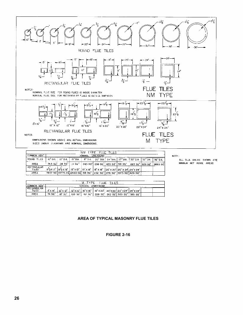
26
FIGURE 2-�6
AREA OF TYPICAL MASONRY FLUE TILES
27
3.1 Breeching ducts are generally less flexible in design location than are water pipes. To avoid conflicts for a given location, design and layout the breeching ducts beforeproceedingwithwaterpipinginthissection.
3.1.1 The purpose of the Section 3.0 is to recommend piping systems and accessories that can be used with Series 8H Modular Gas Boilers. Although recommended design procedures are presented, the final sizing of mains,pumpsandcompressiontankmustbelefttothe designer of the total system because only that designerhasavailabletherequirementsandcapacitiesof the connected system.
3.1.2 Please consider the serviceman who must periodically clean and adjust the boilers and repair accessories. Do not block passageways with piping. Do not block access panels on the boiler jackets.
3.2 MANIFOLDS—Selection of the proper manifolds is importanttothesuccessofthemodularconcept.Oneoftheprimereasonsforusingmodularboilersinsteadofasinglelargeboileristoimprovetheseasonalfuelefficiency. Boiler losses are highest when the burner isoffandtheboilerisstillwarm.Thus,ifonesmallmodule can carry the heating load during mild outdoor weather by nearly continuous firing, a significant loss canbepreventedandgreaterutilizationoffuelcanbemade.However,poorselectionofmanifoldingcanwipeoutpartorallofthepotentialfuelsavingsof the modular system. Some provision should be made to prevent water from flowing through any module when it is not being fired. When warm system water is allowed to flow through any unfired module, heat is being wasted by convection through the chimney and jacket of that unfired module. For example, on an eight module system fired by an eight step sequencer, only one module may be required to meet the connected load demand on a day that is 55°F outdoors. That would be a highly efficient operation. However, if the system water is allowed to flow through the other seven modules, they too are kept warm and the total jacket and flue losses of the eight modules may be as great as that of a single large boiler. Thus, intended benefit is lost.
3.2.1 Figure 3-1 shows a typical parallel pumping system. Parallel pumping of modules does not prevent flow through unfired modules as commonly installed. Thus,parallelpumpingisnotdesirableunlessamotorized valve is used on the supply pipe from each module and controlled to open only when that module is fired. With motorized valves, the owner may find objectionable noise from high velocity water flow under light loads when the entire flow of the system pump is directed through only one module of the group.
3.2.2 By contrast, primary-secondary pumping provides positive flow through each module only when that module is fired. Figure 3-2 shows such a system.
The piping is simple and uses only a single header madeupoffabricatedsteelmanifoldsavailableasoptional equipment. By keeping the head above the top of the modules as shown in Figure 3-2, any gravity circulation from header to unfired modules is prevented. Flow through each fired module is balanced as a result of having its own secondary circulator.
3.2.3 Primary-secondary pumping is preferred as it does accomplish the desired fuel economy. To get the same economy from parallel pumping it is necessary to install some mechanism which will prevent flow through unfired modules as well as to install separate supply and return headers. Thus, the total installed cost of primary-secondary pumping may not be more than that of a properly controlled parallel pumping system.
3.2.4 If after careful consideration, the system designer decides to use parallel pumping, a system using reversereturnheadersasshowninFigure3-1isrecommended.Directreturnheadersarenotrecommended because direct returns are inherently unbalanced and may prevent some modules from deliveringtheirratedcapacities.
3.2.5 Optional fabricated manifolds are available as a convenience to the installer and are highly recommendedwithfourormoremodules.
3.2.5.1 Factory fabricated manifolds are lightweight and quiteforgivingofminorpipingmisalignmentscommontomultipleboilerinstallations.Eachendof the 4” manifold is ready for connection to another manifold section or to the field piping by means of: 1. optional self-restrained pipe couplings, or 2. field roll-grooving for use of groove style couplings.Onelateralconnectiononeachmanifoldis threaded and intended to be made-up first to positively locate the manifold during its installation. Theotherlateralconnectionsoneachmanifoldarelongeralsothreadedforthoseinstallationswherethreaded fittings, such as unions, are desired, but it isrecommendedthattheselongerthreadedlateralsbe cut off to yield plain ends for applying the same style couplings as on the 4” ends.
3.2.5.2 The lateral connections on the factory fabricated manifolds for use with 805H, 806H, and 807H modules are 1½” schedule 40, equally spaced on 28½” centers. The lateral connections on the factory fabricated manifolds for use with 808H, 809H, and 810H modules are 2” schedule 40, equally spaced on 40” centers. If an 807H and an 808H module are to beconnectedtoacommonmanifold,usethelongermanifold with 40” spacing.
3.2.5.3 Manifolds are available to serve two or three modules.Two-modulemanifoldshavetworeturnand two supply lateral connections, three-module manifoldshavethreeofeach.
SECTION 3.0 WATER PIPING
28
3.2.5.4 The manifolds are adaptable to parallel pumping applications by capping half of the lateral connections and using two manifolds: one for supply and one for return. Refer to Figure 3-1.
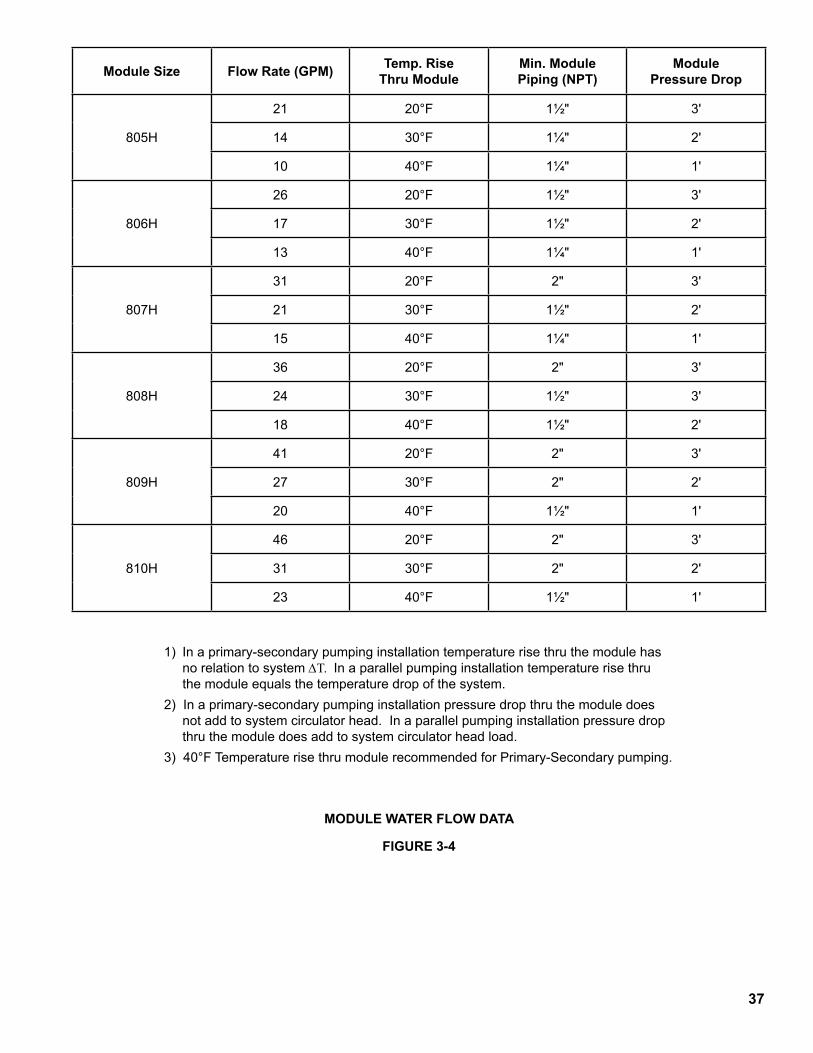
3.2.5.5 A fundamental advantage of primary-secondary pumpingoverparallelpumpingisthatwatertemperature rise and flow rate thru each module in a primary-secondary system is independent of the system temperature drop and flow rate. Hence, modulepipingtoandfromthemanifoldandthe module circulators on a primary-secondary application may be based on a higher temperature rise thru the module, say 30° or 40°F, and downsized fromthelateralconnections.Themodulepiping,valves, and circulator for primary-secondary pumping may be sized from the data in Figure 3-4.
3.2.5.6 For parallel pumping applications module piping shouldequalthelateralconnectionsizes.RefertoFigure 3-4 for module flow rates and pressure drop.
3.2.5.7 The maximum flow capacity of the factory fabricated manifold is 265.GPM. If the system is based on a 20°F ∆T, these manifolds could serve modules with a total input of 3400.MBH. If the system is based on ad 30°F ∆T, these manifolds could serve modules with a total input of up to 5100.MBH.
3.2.5.8 If the optional flex couplings shown in Figures 3-1 through 3-3 are to be used, they should be installed accordingtotheinstructionsinsection3.16.
3.2.5.9 If groove style couplings are to be used, they should beinstalledaccordingtotheinstructionsinsection3.17.
3.2.6 On fewer than four modules, the designer may elect to use commercial schedule 40 pipe and fittings of asmallersizethanthe4”pipesizeofthefabricatedmanifolds.Referto3.4.1fortheprocedureusedtosize a field fabricated manifold. It should be noted that in the case of primary-secondary pumping the returnlinetoeachmoduleshouldnotbedownstreamof the supply line from that same module to avoid shortcircuitingofheatedwaterwithinthatmodule.
3.2.7 On a scaled drawing of the boiler room, layout the selectedwatermanifoldsandmains.
3.3 STOP VALVES—Another prime reason for using modularboilersisthatofservicingwithoutshuttingdown the entire system. Any individual module canbeshutdownforcleaningorrepairswithoutinterruptingtheoperationoftheremainingmodules.Thisistrueofelectricalcomponentsandthegascomponentsbecausemostcodesrequireaserviceshutoff at each module. A mistake is often made by not installingwaterstopvalvesattheheadersforeachmodule. By installing stop valves at the headers for each module it becomes easy to perform repairs to the water side of the module, such as leaky fittings, control wells, and pumps. Without stop valves eachsuchservicecallresultsintheaggravationofasystem shut down. In addition, it takes time for the serviceman to drain before the repairs and then refill and vent the system after the repairs. That additional
service time may cost the owner more over the life of the system than the cost of the stop valves at the time of installation. Finally, the use of water side stop valves on each module is required by some codes inordertoexcludetheheaderandinter-connectingwaterpipingfromconsiderationasanintegralpartofaboiler.StopvalvesarerecommendedasshowninFigures3-1through3-3.
3.4 TEMPERATURE DROP—Selection of temperature drop has received attention in recent years as a means ofreducingpipingorpumpingcosts.Overseveralprevious decades the 20°F water temperature drop had been standard for the hydronics industry. Recently, temperature drops of 30°F, 40°F and even 50°F have been used successfully when the distribution system and terminal units are properly sized for these larger temperaturedrops.Innewconstructionitisadvisabletoconsiderthesavingsinmaterialsthatcanbemadeby designing with a temperature drop larger than 20°F.
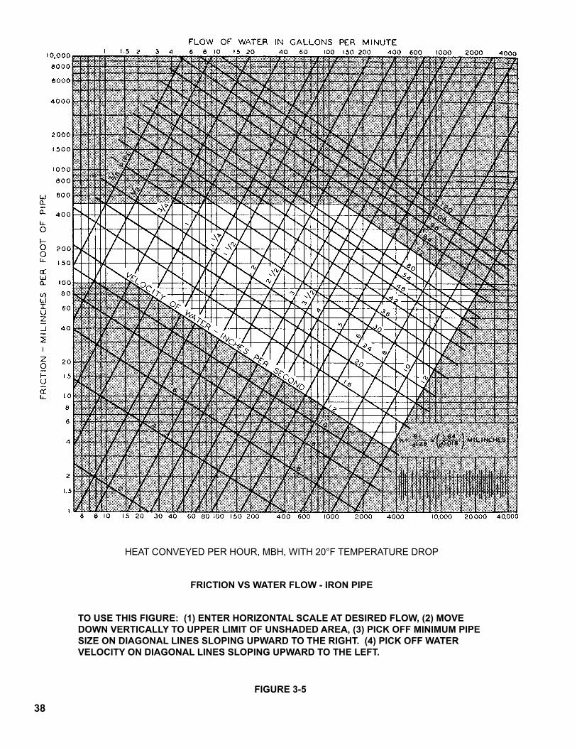
3.4.1 Figure 3-5 is a typical friction-velocity-flow diagram used by most designers of large systems. The lower scale, Heat Conveyed, is based on a 20°F temperature drop. However, the flow rate in gpm is shown on theupperscale,andcanbeusedtosizepipeatothertemperature drops by converting heat conveyed to flow rate in gpm. Example: Find the pipe size required to convey
1,000,000 Btuh in iron pipe at a friction loss of 500 mill inches/ft. and temperature drops of 20°F, 30°F or 40°F.
Solution: The gpm flow rate for 1,000,000 Btuh is found by dividing:
1,000,000 by (500 x 20) = 100 gpm for 20° drop 1,000,000 by (500 x 30) = 66.7 gpm for 30° drop 1,000,000 by (500 x 40) = 50 gpm or 40° drop Enter Figure 3-5 on the horizontal line for 500 mill
inchesperft.andreadacrosstotherighttothevertical lines for 100 gpm, 66.7 gpm and 50 gpm.
Ontheslantedlinesreadthecorrespondingpipesizes(usethelargerifbetweentwopipesizes)
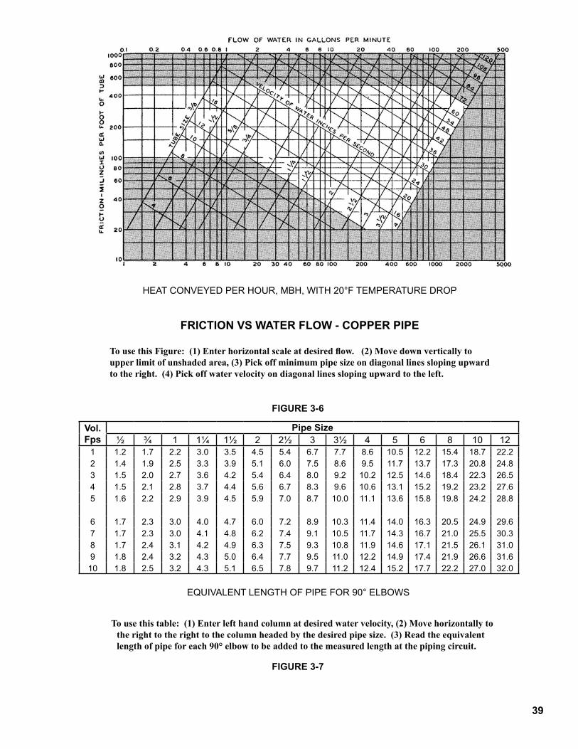
100 gpm = 3” Pipe 66.7 gpm = 2½” Pipe 50 gpm = 2½” Pipe Figure3-6canbeusedinasimilarmannerfor
copperpipe.3.4.2Thesizeoftheterminalunits(baseboard,convectors,
fan coils, etc.) must be adjusted according to the actual temperature of water flowing in those units. In general, the first terminal unit on a circuit will receive hotterthanaveragewaterandshouldbeundersized,andthelastterminalunitwillreceivecoolerthanaveragewaterandshouldbeoversized.Thedesignershouldconsultasizingproceduresuchasthatcontained in the ASHRAE Guide or I=B=R Guide #250.
3.4.3 It should be noted that the selection of system temperaturedrophasnoeffectonthesizingoftheboiler.
2�
3.4.4 On remodeling jobs it is generally too expensive to modify the terminal units for temperature drops other than that used by the original system designer. It isnot“safe”toassumethattheoriginaldesignwasbased on 20°F drop and thus the owner’s records shouldbeconsulted.
3.5 MAIN PIPING—Selection of Main Size and the system pump must go together. The system designer can select the pump and size the pipe accordingly, butmoreoftenthebesteconomicsofpipeandpumpcauses the system designer to select the minimum pipesizebasedonamaximumpressuredropandthen select a pump(s) to meet flow and pressure drop requirements of the total system. It is recommended thatpipesizesbeselectedintheunshadedportionsofFigure 3-5 or 3-6. The minimum pipe size will occur onorclosetotheupperlimitoftheunshadedareas.
Example: Find the minimum main size and corresponding friction for three 808H modules using iron pipe and a 20°F temperature drop.Solution:1) The output of three 808H modules is 3 x 462 x
.80 = 1,109 MBH. Refer to Figure 2-3 for module inputandFigure2-1forinputtooutputmultiplier.
2) Enter Figure 3-5 on the lower horizontal scale at 1,109 MBH and move vertically to the upper limit oftheunshadedarea.
3) Onthelinesthatslantupwardtotheright,readthepipesize.Inthiscase,thepipesizeisgreaterthan2½” but less than 3”. Select the larger of 3”.
4) From the point in 2) above move down vertically to the 3” pipe line and horizontally to the left hand scale. Pick off 300 mill inches per foot friction.
3.5.1 In calculating the total equivalent length of pipe it is necessary to consider the additional resistance of elbows. Figure 3-7 shows the equivalent lengths. Thetotalequivalentlengthofpipeinacircuitisthemeasuredlengthplustheequivalentlengthofallelbowsinthatcircuit.Thetotalequivalentlengthof the longest circuit in the system is useful in determining the head requirement of the system pump.
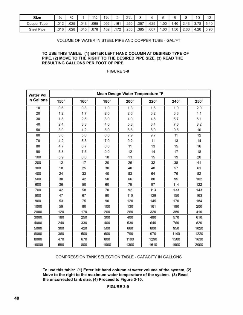
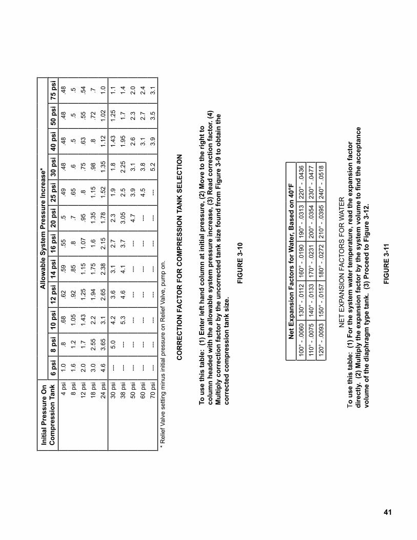
3.6 COMPRESSION TANK—Selection of the compressiontankmustbebasedonthefollowingitems:
a) volume of water in the systemb) initial fill pressure of the systemc) maximum operating pressure of the systemd) maximumoperatingtemperatureofthe
system3.6.1 It is necessary to calculate the volume of water
contained in the total system including piping, modules and terminal units. Figure 3-8 can be used to determine the volume of the piping by measuring the length of each size of pipe and multiplying by the appropriate factor from Figure 3-8.
Example: Find the water volume in the piping of a system having 40’ of 3” pipe, 72’ of 2” pipe, and 52’ of1¼”pipe.
Solution: From Figure 3-8 obtain the gallons/ft. from each size of pipe and multiply by the length of thatsizeofpipe.
1¼” Copper = .065 gal/ft x 52 Ft = 3.4 Gal. + 2” Copper = .161 gal/ft x 72 Ft = 11.6 Gal. + 3” Copper = .357 gal/ft x 40 Ft = 14.3Gal. Totalvolumeinpiping=29.3Gal.
3.6.1.1UseFigure3-13tocalculatethevolumeofthemodules.
Example: Find the volume of water in four 806H modules.
Solution: From Figure 3-13 find that the water volume of one 806H is 13.9 gallons and multiply by the number of modules:
13.9 x 4 = 55.6 gallons in the modules.3.6.1.2Thewatersideofterminalunitsmustbeknownin
ordertodeterminetheirvolume.Tubularunitssuchas baseboard, commercial finned tube, convectors and fan coils can be computed by knowing the lengthandsizeofthetubes.
Example: Find the water volume in 528 ft. of 1¼” copper dual tiered commercial finned tube.
Solution: From Figure 3-8 obtain the value of .065 gal/ft. for 1¼” copper and multiply by 528 ft. and by 2 tiers:
0.65 gal/ft x 528 ft x 2 tiers = 68.6 Gallons in the FinnedTube.
3.6.1.3Fromtheaboveexamplesthetotalvolumeofthesystem can be added:
Volumeofpiping =29.3Gal. + Volume of modules = 55.6 Gal. +VolumeofFinnedTube =68.6Gal. Total Volume of System = 153.5 Gal.
3.6.2 Conventional compression tanks can be sized by using Figures 3-9 and 3-10. Enter Figure 3-9 in the left hand column at the water volume of the system, move acrosstotherighttothemaximumwatertemperatureof the system and read the uncorrected tank size.
To find the correction factor, enter Figure 3-10 in the left hand column of the initial fill pressure and move across to the right to column for the system pressure increase and read the tank correction factor. Multiply the uncorrected tank size by the correction factor to find the final tank size.
Example: Find the conventional compression tank size for a system having a water volume of 153.5 gallons, a design water temperature of 240°F, a 50 psi relief valve and a system height of 30 Ft.
Solution:1) EnterFigure3-9inthelefthandcolumnandmove
down to 200 gallons (which is the next largest value to 153.5 gallons). Read across to the column for 240 design water temperature and read 38 gallonsuncorrectedtanksize.
2) Find the initial fill pressure by multiplying the system height by 0.433:
30 x 0.433 = 13 psi
30
3) Enter Figure 3-10 in the left hand column and move down to 12 psi fill pressure (closest to 13 psi). Move across to the column headed 40 psi pressure increase (closest column to 40 psi minus 13 psi) and read a correction factor of 0.63
4) Multiply 0.63 x 38 Gal. = 24 gallons corrected tank size.
5) Select a conventional compression tank size of at least 24 gallons. In some cases, greater accuracy may be obtained by interpolation in Figures 3-9 and 3-10.
3.6.3 Diaphragm type compression tanks can be sized by usingFigures3-11and3-12.FindtheexpansionfactorforwateratthedesignwatertemperaturefromFigure 3-11. Multiply that expansion factor by the volume of the system to obtain the acceptance volume ofthecompressiontank.
Find the tank volume by dividing the acceptance volume by the acceptance factor from Figure 3-12.
Example: find the diaphragm type tank size for the same system as in 3.6.2 above.
Solution:1) From Figure 3-11 at 240°F design temperature read
an expansion factor of .0518.2) Multiply the system volume by the expansion
factor: Acceptance volume = 153.5 Gal x .0518 = 8
gallons3) Enter figure 3-12 at a fill pressure of 13 psi and
a final pressure of 50 psi and read the acceptance factor of 0.58.
4) Tank volume = 8 gallons ‘ 0.58 = 14 gallons5) Select a diaphragm type tank having a minimum
acceptance volume of 8 gallons and a tank volume ofatleast14gallons.
3.7 LOW WATER CUTOFF—On each modular install-ationatleastonelowwatercutoffisrequired.If,asrecommendedin3.3,modulesareinstalledwithshutoff valves in their respective supply and return pipingtothemanifoldtheneachmodulewillrequireadedicated LWCO. Otherwise, a system LWCO will be required.
3.7.1 If a system LWCO is to be used, such as shown in Figure3-1or3-2,itmustbeinstalledonthereturnmainatanelevationhigherthanthemodulesandfill valve. The pipes connecting from the main to the system LWCO must be teed into the return main using the shortest possible 1” pipe and fewest fittings. SeeFigure3-1or3-2.Donotinstallvalvesbetweenthe return main and the system LWCO. If for any reason,theelevationofamoduleisdifferentfromanother module in the group, the system LWCO must beinstalledabovethemodulehavingthehighestelevation.
3.7.2 If dedicated LWCO’s are to be used they must be installedbetweeneachmoduleanditsrespectiveshutoffvalveandatanelevationhigherthanthe
module and its fill valve. A probe style LWCO isavailableasanoptionanditsrecommendedinstallation location is in the module’s supply riser tothemanifoldasdepictedinFigures3-2and3-3.Do not install any valve between the module and its respective LWCO.
3.8 RELIEF VALVE—Each Series 8H module is supplied withitsownpressurereliefvalve.Noadditionalreliefvalvesneedbeinstalledonthemanifolds.Ifdomesticwaterheatingisaddedtoamodule,itisrecommendedthatareliefvalvebeinstalledasshowninFigure3-14.
3.9 LIMIT CONTROL—Each Series 8H module is suppliedwithitsownhighlimitcontrol.TomeetASME requirements, a second operating control must be placed in the supply header downstream of the last module but upstream of any valve on the supply main. The size and type of control well will depend on the control system selected in Section 5.0. Note: The local jurisdiction may require that the high limit on the module be of the manual reset type.
3.10 PRESSURE & TEMPERATURE GAUGE—Each Series 8H module is supplied with its own Tridicator sothattheperformanceofeachmodulecanbeobservedwithoutinstallationofadditionalgauges.
3.11 FILL VALVE—An automatic fill valve is recommendedtomaintaintheminimumpressureinthe system at the fill pressure required by the height of the piping system.
3.12 SYSTEM CIRCULATOR—To avoid placing the head pressure of the system circulator on the boiler and compression tank, the system circulator should be installed such that it pumps away from the boiler and compressiontank.SeeFigures3-1and3-2.
3.13 DOMESTIC WATER HEATING—An external water heater may be added to any module on either primary-secondary or parallel circulation system. If heavy waterheatingloadsareanticipatedanadditionalmodule(s) may be added to the water heating circuit. RefertoFigure3-14forrecommendedmodulewaterpipingfordomesticwaterheating,withparallelpiping.RefertoFigure3-3forrecommendedpipngwhen using an Alliance Indirect hot water tank with Primary Secondary Piping.
3.13.1 Water heater size may be determined in the following manner:
1) From Figure 3-15, find the appropriate factor for each fixture in the building and add them together to find the total fixture units.
2) From Figure 3-16, convert the fixture units to hot water capacity in gallons per minute based on 40-140°F temperature rise.
3) Selectwaterheaterbasedongallonsperminutefrom2)above.
3.13.2 The addition of water heating may not necessarily addtothesizeofthemodules.Sincethemaximumspaceheatingleadandthemaximumwaterheating
3�
load rarely occur at the same time, only a portion of thewaterheatingloadisaddedtothespaceheatingload to size the modules as follows:
1) Calculate the water heating load in Btuh: __________gpm x 8.33 Lb/Gal x 60 Min/Hr x 100
∆T = ___________Btuh2) Calculateratio=WaterHeatingLoad SpaceHeatingLoad3) From Figure 3-17, using the ratio found in 2), find
factor for sizing the “boiler added capacity”.4) Calculate “boiler added capacity” by multiplying
factor from 3) by water heating load.5) Total the space heating load and the “boiler added
capacity”, and convert this total load to total input by using the 1.44 multiplier from Figure 2-1.
6) SelectmodulesfromFigure2-2usingthistotalinput.
7) Convert the input of one module (found in Figure 2-3) to Gross Output by using the .80 multiplier fromFigure2-1.
8) Divide water heating load by gross output of one moduletodeterminethenumberofmodulestobeusedinthewaterheatingcircuit.
Example #1—An office building has 12 basins and 2 slop sinks and a space heating load of 1,403,500 Btuh. Sizethewaterheaterandboiler.Solution:1) 12basinsx¾units =9FixtureUnits +2 slop sinks x 1½ units = 3FixtureUnits Total =12FixtureUnits2) In Figure 3-16, using curve “C” for office building,
find that for 12 Fixture Units 6 gpm is required.3) Select water heater at 6 gpm and 40-140°F
temperaturerise.4) CalculatewaterheatingloadinBtu. 6 x 8.33 x 60 x 100 = 299,880 Btuh5) Calculate ratio = Water Heating SpaceHeating =299,880=.22 1,403,5006) From Figure 3-17 find that for a ratio of less than
.25 the boiler added capacity is 0%.7) Convert the total load (1,403,500 + 0 Btuh) to total
Input: 1,403,500 Btuh x 1.44 = 2,021 MBH Input 1000 Btuh/MBH8) Enter Figure 2-2 at 2,046 MBH Input (closest
Input over 2,021 MBH) and select (1) 806H and (3) 807H modules as the most economical combinationofmodules.
9) ConverttheInputofonemoduletoGrossOutputusing Figures 2-1 and 2-3:
806H 330 MBH x .80 x 1000 Btuh MBH = 264,000 Btuh Gross Output
807H 396 MBH x .80 x 1000 Btuh MBH = 316,800 Btuh Gross Output
10) The water heating load of 299,880 Btuh could be handled by any one of the 807H modules:
299,880 = (1) 807H module 316,800
Example #2: an apartment building has 12 basins, 12 kitchensinks,14showers,12dishwashersand2slopsinks. The design space heating load is 772,000 Btuh. Sizethewaterheaterandboiler.Solution:1) From Figure 2-15: 12basinsx¾units =9FixtureUnits +12sinksx¾units =9 + 14 showers x 1½ units = 21 + 12 dishwashers x 1½ units = 18 + 2 slop sinks x 1½ units =3 Total Fixture Units = 60 2) From figure 3-16 using curve “B” for apartment
houses, find 27 gpm for 60 fixture units.3) Select a water heater having a capacity of 27 gpm
at 40-140° F temperature rise.4) Calculate the water heater load: 27 x 8.33 x 60 x
100 = 1,349,500 Btuh5) Calculate ratio = Water Heating SpaceHeating =1,349,500 = 1.75 772,0006) From Figure 3-17 and a ratio of 1.75 find factor of
.84.7) Net rating of boiler = .84 x 1,349,500 + 772,000 =
1,905,550 Btuh8) Required modular Input = 1,905,550 Btuh x 1.44 = 2,744 MBH Input 1000 Btuh/MBH9) Module selection from Figure 2-2 is (3) 809H and
(2) 810H modules.10) Module Gross Output:
809H 528 x .80 x 1000 = 422,400 Btuh 810 594 x .80 x 1000 = 475,200 Btuh
11) Number of modules in water-heating circuit: 1,349,500 = (1) 809H & (2) 810H 422,400 + (2) 475,200 modules
3.13.3Thedomesticwaterheatersizingprocedures outlinedinthissectionarebasedonmethods recommendedintheASHRAE HANDBOOK andProduct Directory, Systems Volume, “Service Water Heating”Chapter.
3.14 PIPING MATERIAL supplied on a Series 8H packagedboiler,orinthewatertrimcartonofaSeries 8H knockdown, consists of the following:
32
Quantity1 Altitude Temperature & Pressure Gauge
2½” Dia., 60-320°F, 0-75 PSIG1 ¾” ASME Safety Relief Valve set at 50 PSI—
ConBraCo or Watts1 ¾”DrainCock1 ¾”PipeCoupling—ForDrain1 2” x 10” Pipe Nipple—For Supply Piping1 2” x ¾” x 2” Tee—For Supply Piping1 ¾” x ¼” Pipe Bushing—For Supply Piping1 ¾”xClosePipeNipple—ReliefValvePiping1 ¾”x2”PipeNipple—ReliefValvePiping2 ¾” x 3½” Pipe Nipple—Relief Valve Piping and
Drain1 ¾”—90° Ell—Relief Valve Piping1 ¾”Tee—ReliefValvePiping
3.15 Piping components recommended for primary- secondary pumping are depicted in Figure 3-3.
3.16 Installation procedure for optional flex couplings.3.16.1PipeEndPreparation
a) 4” ends of fabricated manifolds: with a manual or automatic pipe cutter, cut 1-1/8” off each end ofthemanifoldtoprovidethepropergapbetweenpipeends.
b) 1½” or 2” laterals of fabricated manifolds: with a manual pipe cutter, cut 1½” off each of the 4” long lateralstoremovethepipethreads.Donotcutthe threads off the shorter 2½” long lateral, as this connectionisintendedtobepipedrigidtolocatethemanifoldduringinstallation.Ifthemanifoldistobeusedforparallelpumping,donotcutthethreadsoffthelateralsthataretobecapped.
c) Deburrandcleanpipeends.d) Special surface finish on pipe is not required.
Surfacetobefreeofdeepscratches,gouges,dents,etc.
3.16.2 JointInstallationa) Installretainer(1),gasket(2)andsleeve(3)onone
pipeendormanifoldinsequenceshownbelow.
b) Install remaining retainer (4) and gasket (5) on otherpipeendormanifold.
c) Position retainer (4) and gasket (5) to proper pipe insertion depth “D”:
PipeSizePipeInsertionDepth
Nominal Max. Min.1-1/2" 1-3/8" 1.62" 1.16"
2" 1-1/2" 1.84" 1.18"4" 2-1/16" 2.44" 1.74"
3.16.4 SpecialNotesa) Assembly of gaskets can be made easier by
dippinggasketsinwaterorwipingthemwithasmallamountofliquidhandsoap.Otherrubberlubricantscannotbeused.
b) To simplify installation of the self-restrained gasket, install the lower half of the gasket first, leavingthesplitareainthesteelretainingringfreeatthetop.Then,stretchthegasketandsplitareaofthe retaining ring until they slip over the pipe and intopositionasshownbelow.
c) These self-restrained joints are recommended for use on elbows and tees because they are capable of supporting end loads caused by internal pressureuptotheirratedoperatingpressureof80 psi. Recommended assembly torque must be maintainedtowithstandtheseendloads.
d) The gaskets supplied with the flex couplings are specifically formulated for boiler water service (—20°F to 275°F) and are compatible with antifreezeandcorrosioninhibitors.Useofothergasket materials is not recommended and may resultinlossofseal!
d) Slide sleeve (3) to gasket (5) and move gasket (2) andretainer(1)intopositionasshown.
Pipemustbeinsertedtoproperdepth“D”intobothgaskets.
3.16.3 CouplerInstallation InstallbothV-couplings,encompassingthe
retainer,gasketandsleeve.Donottighteneithercoupling until entire joint has been assembled. Tighten nuts of 4” couplings to 280-300 inch-lbs. and 1½” and 2” couplings to 140-160 inch-lbs., or to a minimum of 1/16” clearance between coupling lugs, whichever occurs first. Retightening of the coupler will be necessary if leakage occurs. A completedV-couplinginstallationisshownbelow.
33
3.16.5 Laying Length of Coupling The axial spacing, or gap, between pipe ends joined
by the optional flex couplings is variable within these limits:
3.17.3 Gasket and Coupling Installation Specific installation procedures vary from one
couplingmanufacturertoanother.Followthecouplingmanufacturer'srecommendationsforinstallation.
3.18 STRAINERS—A start-up strainer is recommended for practically all modular installations (new and replacement alike) to prevent system debris and sedimentfromendingupintheboilerswhereitwillinhibit heat transfer and may eventually cause a cast ironsectiontocrackfromoverheating.
3.19 OXYGEN CORROSION:3.19.1 Oxygen contamination of the boiler water will cause
corrosionoftheironandsteelboilercomponents,which can lead to failure. As such, any system must be designed to prevent oxygen absorption in the first place or prevent it from reaching the boiler. Problems caused by oxygen contamination of boiler water are not covered by Burnham's standard warranty.
3.19.2 There are many possible causes of oxygen contamination such as:a. Addition of excessive make-up water as a result
of system leaks.b. Absorption through open tanks and fittings.c. Oxygen permeable materials in the distribution
system.3.19.3 In order to insure long product life, oxygen sources
should be eliminated. This can be accomplished by taking the following measures:a. Repairing system leaks to eliminate the need for
additionofmake-upwater.b. Eliminating open tanks from the system.c. Eliminating and/or repairing fittings which allow
oxygen absorption.d. Useofnon-permeablematerialsinthe
distribution system.e. Isolating the boiler from the system water by
installingaheatexchanger.
PipeSizeLayingLength(Gap)
Nominal Max. Min.1-1/2" 3/4" 1-3/16" 1/4"
2" 1" 1-5/8" 3/8"4" 2-3/8" 3" 1-3/4"
3.16.6Misalignment Inadditiontotheaxialmisalignmenttabulated
in 3.16.5 the flex couplings permit a 4° angular installationmisalignmentateachend.
3.17 Installation notes for V-groove couplings.3.17.1 Pipe End Preparation
a) 4" ends of fabricated manifolds: since the 4" pipe of the manifold is schedule 10, the ends should be roll-grooved.DONOTcut-groovethe4"endsofthefabricatedmanifolds.
b) 1½" or 2" laterals of fabricated manifolds: with a manual pipe cutter, cut 1½" off each of the 4" long lateralstoremovethepipethreads.Donotcutthe threads off the shorter 2½" long lateral, as this connectionisintendedtobepipedrigidtolocatethemanifoldduringinstallation.Ifthemanifoldistobeusedforparallelpumping,donotcutthethreadsoffthelateralsthataretobecapped.Thelaterals are schedule 40 so those intended for V-groove couplings may be roll-grooved or cut-grooved.
3.17.2 Gasket Material Selectionofagasketmaterialisofutmost
importance!Itmustmaintainaleaktightsealformany years at the temperatures and pressures of ahotwaterboilerandwithstandtheattackofthecorrosioninhibitorsandantifreezescommontohotwater system. In general neoprene, nitrile, Buna-N, EPDM, and butyl are not acceptable gasket materials because they either are not resistant to the fluids or are not capable of continuous use at 250°F.
34
PIPI
NG
DIA
GR
AM
(2 B
OIL
ERS)
, PA
RA
LLEL
WIT
H B
LEN
D P
UM
P A
ND
SyS
TEM
PU
MP
FIG
UR
E 3-
�
35
PIPI
NG
DIA
GR
AM
(2 B
OIL
ERS)
, PR
IMA
Ry/S
EcO
ND
ARy
WIT
H B
y-PA
SS A
ND
SyS
TEM
PU
MP
FIG
UR
E 3-
2
36
PIPI
NG
DIA
GR
AM
- ZO
NE
PUM
PS, P
RIM
ARY
/SEC
ON
DA
RY W
/ ALL
IAN
CE
DH
W &
REC
IRC
. LO
OP
WIT
H M
OD
ULA
R M
AN
IFO
LDS
FIG
UR
E 3-
3
37
MODULE WATER FLOW DATA
FIGURE 3-4
1)Inaprimary-secondarypumpinginstallationtemperaturerisethruthemodulehasnorelationtosystem∆T.Inaparallelpumpinginstallationtemperaturerisethruthemoduleequalsthetemperaturedropofthesystem.2)Inaprimary-secondarypumpinginstallationpressuredropthruthemoduledoesnotaddtosystemcirculatorhead.Inaparallelpumpinginstallationpressuredropthruthemoduledoesaddtosystemcirculatorheadload.3)40°FTemperaturerisethrumodulerecommendedforPrimary-Secondarypumping.
Module Size Flow Rate (GPM) Temp. RiseThru Module
Min. ModulePiping (NPT)
ModulePressure Drop
805H
21 20°F 1½" 3'
14 30°F 1¼" 2'
10 40°F 1¼" 1'
806H
26 20°F 1½" 3'
17 30°F 1½" 2'
13 40°F 1¼" 1'
807H
31 20°F 2" 3'
21 30°F 1½" 2'
15 40°F 1¼" 1'
808H
36 20°F 2" 3'
24 30°F 1½" 3'
18 40°F 1½" 2'
809H
41 20°F 2" 3'
27 30°F 2" 2'
20 40°F 1½" 1'
810H
46 20°F 2" 3'
31 30°F 2" 2'
23 40°F 1½" 1'
38
HEATCONVEYEDPERHOUR,MBH,WITH20°FTEMPERATUREDROP
FRICTION VS WATER FLOW - IRON PIPE
TO USE THIS FIGURE: (1) ENTER HORIzONTAL ScALE AT DESIRED FLOW, (2) MOVE DOWN VERTIcALLy TO UPPER LIMIT OF UNSHADED AREA, (3) PIck OFF MINIMUM PIPE SIzE ON DIAGONAL LINES SLOPING UPWARD TO THE RIGHT. (4) PIck OFF WATER VELOCITY ON DIAGONAL LINES SLOPING UPWARD TO THE LEFT.
FIGURE 3-5
3�
HEATCONVEYEDPERHOUR,MBH,WITH20°FTEMPERATUREDROP
FRICTION VS WATER FLOW - COPPER PIPE
To use this Figure: (1) Enter horizontal scale at desired flow. (2) Move down vertically to upper limit of unshaded area, (3) Pick off minimum pipe size on diagonal lines sloping upward to the right. (4) Pick off water velocity on diagonal lines sloping upward to the left.
FIGURE 3-6
EQUIVALENTLENGTHOFPIPEFOR90°ELBOWS
To use this table: (1) Enter left hand column at desired water velocity, (2) Move horizontally to the right to the right to the column headed by the desired pipe size. (3) Read the equivalent length of pipe for each 90° elbow to be added to the measured length at the piping circuit.
FIGURE 3-7
Vol. Fps
Pipe Size½ ¾ 1 1¼ 1½ 2 2½ 3 3½ 4 5 6 8 10 12
1 1.2 1.7 2.2 3.0 3.5 4.5 5.4 6.7 7.7 8.6 10.5 12.2 15.4 18.7 22.22 1.4 1.9 2.5 3.3 3.9 5.1 6.0 7.5 8.6 9.5 11.7 13.7 17.3 20.8 24.83 1.5 2.0 2.7 3.6 4.2 5.4 6.4 8.0 9.2 10.2 12.5 14.6 18.4 22.3 26.54 1.5 2.1 2.8 3.7 4.4 5.6 6.7 8.3 9.6 10.6 13.1 15.2 19.2 23.2 27.65 1.6 2.2 2.9 3.9 4.5 5.9 7.0 8.7 10.0 11.1 13.6 15.8 19.8 24.2 28.8
6 1.7 2.3 3.0 4.0 4.7 6.0 7.2 8.9 10.3 11.4 14.0 16.3 20.5 24.9 29.67 1.7 2.3 3.0 4.1 4.8 6.2 7.4 9.1 10.5 11.7 14.3 16.7 21.0 25.5 30.38 1.7 2.4 3.1 4.2 4.9 6.3 7.5 9.3 10.8 11.9 14.6 17.1 21.5 26.1 31.09 1.8 2.4 3.2 4.3 5.0 6.4 7.7 9.5 11.0 12.2 14.9 17.4 21.9 26.6 31.6
10 1.8 2.5 3.2 4.3 5.1 6.5 7.8 9.7 11.2 12.4 15.2 17.7 22.2 27.0 32.0
40
VOLUMEOFWATERINSTEELPIPEANDCOPPERTUBE-GAL/FT
TO USE THIS TABLE: (1) ENTER LEFT HAND cOLUMN AT DESIRED TyPE OF PIPE, (2) MOVE TO THE RIGHT TO THE DESIRED PIPE SIzE, (3) READ THE RESULTING GALLONS PER FOOT OF PIPE.
FIGURE 3-8
COMPRESSIONTANKSELECTIONTABLE-CAPACITYINGALLONS
To use this table: (1) Enter left hand column at water volume of the system, (2) Move to the right to the maximum water temperature of the system. (3) Read the uncorrected tank size, (4) Proceed to Figure 3-10.
FIGURE 3-�
Size ½ ¾ 1 1¼ 1½ 2 2½ 3 4 5 6 8 10 12CopperTube .012 .025 .043 .065 .092 .161 .250 .357 .625 1.00 1.40 2.43 3.78 5.40SteelPipe .016 .028 .045 .078 .102 .172 .250 .385 .667 1.00 1.50 2.63 4.20 5.90
Water Vol. In Gallons
Mean Design Water Temperature °F
150° 160° 180° 200° 220° 240° 250°10 0.6 0.8 1.0 1.3 1.6 1.9 2.020 1.2 1.7 2.0 2.6 3.2 3.8 4.130 1.8 2.5 3.0 4.0 4.8 5.7 6.140 2.4 3.3 4.0 5.3 6.4 7.6 8.250 3.0 4.2 5.0 6.6 8.0 9.5 1060 3.6 5.0 6.0 7.9 9.7 11 1270 4.2 5.8 7.0 9.2 11 13 1480 4.7 6.7 8.0 11 13 15 1690 5.3 7.5 9.0 12 14 17 18
100 5.9 8.0 10 13 15 19 20200 12 17 20 26 32 38 41300 18 25 30 40 48 57 61400 24 33 40 53 64 76 82500 30 42 50 66 80 95 102600 36 50 60 79 97 114 122700 42 58 70 92 113 133 143800 47 67 80 110 129 150 163900 53 75 90 120 145 170 184
1000 59 80 100 130 161 190 2002000 120 170 200 260 320 380 4103000 180 250 300 400 480 570 6104000 240 330 400 530 640 760 8205000 300 420 500 660 800 950 10206000 360 500 600 790 970 1140 12208000 470 670 800 1100 1290 1500 1630
10000 590 800 1000 1300 1610 1900 2000
4�
cO
RR
EcTI
ON
FA
cTO
R F
OR
cO
MPR
ESSI
ON
TA
Nk
SEL
EcTI
ON
To u
se th
is ta
ble:
(1)
Ent
er le
ft ha
nd c
olum
n at
initi
al p
ress
ure,
(2) M
ove
to th
e rig
ht to
co
lum
n he
aded
with
the
allo
wab
le s
yste
m p
ress
ure
incr
ease
, (3)
Rea
d co
rrec
tion
fact
or. (
4)
Mul
tiply
cor
rect
ion
fact
or b
y th
e un
corr
ecte
d ta
nk s
ize
foun
d fr
om F
igur
e 3-
9 to
obt
ain
the
corr
ecte
d co
mpr
essi
on ta
nk s
ize.
FIG
UR
E 3-
�0
NETEXPA
NSIONFACTO
RSFORW
ATER
To u
se th
is ta
ble:
(1)
For
the
syst
em w
ater
tem
pera
ture
, rea
d th
e ex
pans
ion
fact
or
dire
ctly
. (2
) Mul
tiply
the
expa
nsio
n fa
ctor
by
the
syst
em v
olum
e to
find
the
acce
ptan
ce
volu
me
of th
e di
aphr
agm
type
tank
. (3
) Pro
ceed
to F
igur
e 3-
12.
FIG
UR
E 3-
��
Initi
al P
ress
ure
On
Com
pres
sion
Tan
kA
llow
able
Sys
tem
Pre
ssur
e In
crea
se*
6 ps
i8
psi
�0 p
si�2
psi
�4 p
si�6
psi
20 p
si25
psi
30 p
si40
psi
50 p
si75
psi
4ps
i1.
0.8
.68
.62
.59
.55
.5.4
9.4
8.4
8.4
8.4
88
psi
1.6
1.2
1.05
.92
.85
.8.7
.65
.6.5
.5.5
12p
si2.
01.
71.
431.
251.
151.
07.9
5.8
.75
.63
.55
.54
18p
si3.
02.
552.
21.
941.
751.
61.
351.
15.9
8.8
.72
.724
psi
4.6
3.65
3.1
2.65
2.38
2.15
1.78
1.52
1.35
1.12
1.02
1.0
30p
si---
5.0
4.2
3.6
3.1
2.7
2.3
1.9
1.8
1.43
1.25
1.1
38p
si---
---
5.3
4.6
4.1
3.7
3.05
2.5
2.25
1.95
1.7
1.4
50p
si---
---
---
---
---
---
4.7
3.9
3.1
2.6
2.3
2.0
60p
si---
---
---
---
---
---
---
4.5
3.8
3.1
2.7
2.4
70p
si---
---
---
---
---
---
---
---
5.2
3.9
3.5
3.1
*ReliefValvesettingminusinitialpressureonReliefValve,pum
pon.
Net
Exp
ansi
on F
acto
rs fo
r Wat
er, B
ased
on
40°F
100°-.0060
130°-.0112
160°-.0190
190°-.0313
220°-.0436
110°-.0075
140°-.0133
170°-.0231
200°-.0354
230°-.0477
120°-.0093
150°-.0157
180°-.0272
210°-.0395
240°-.0518
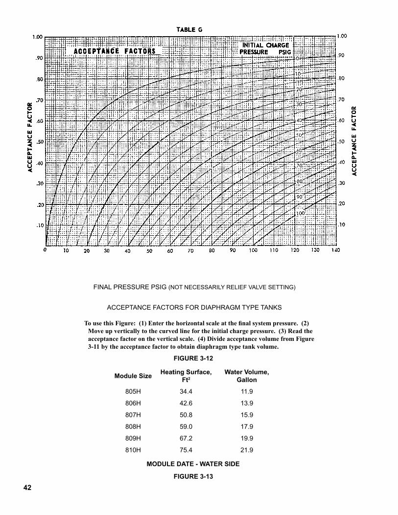
42
FINALPRESSUREPSIG(NOTNECESSARILYRELIEFVALVESETTING)
ACCEPTANCEFACTORSFORDIAPHRAGMTYPETANKS
To use this Figure: (1) Enter the horizontal scale at the final system pressure. (2) Move up vertically to the curved line for the initial charge pressure. (3) Read the acceptance factor on the vertical scale. (4) Divide acceptance volume from Figure 3-11 by the acceptance factor to obtain diaphragm type tank volume.
FIGURE 3-�2
FIGURE 3-�3
Module Size Heating Surface, Ft2
Water Volume, Gallon
805H 34.4 11.9
806H 42.6 13.9
807H 50.8 15.9
808H 59.0 17.9
809H 67.2 19.9
810H 75.4 21.9
MODULE DATE - WATER SIDE
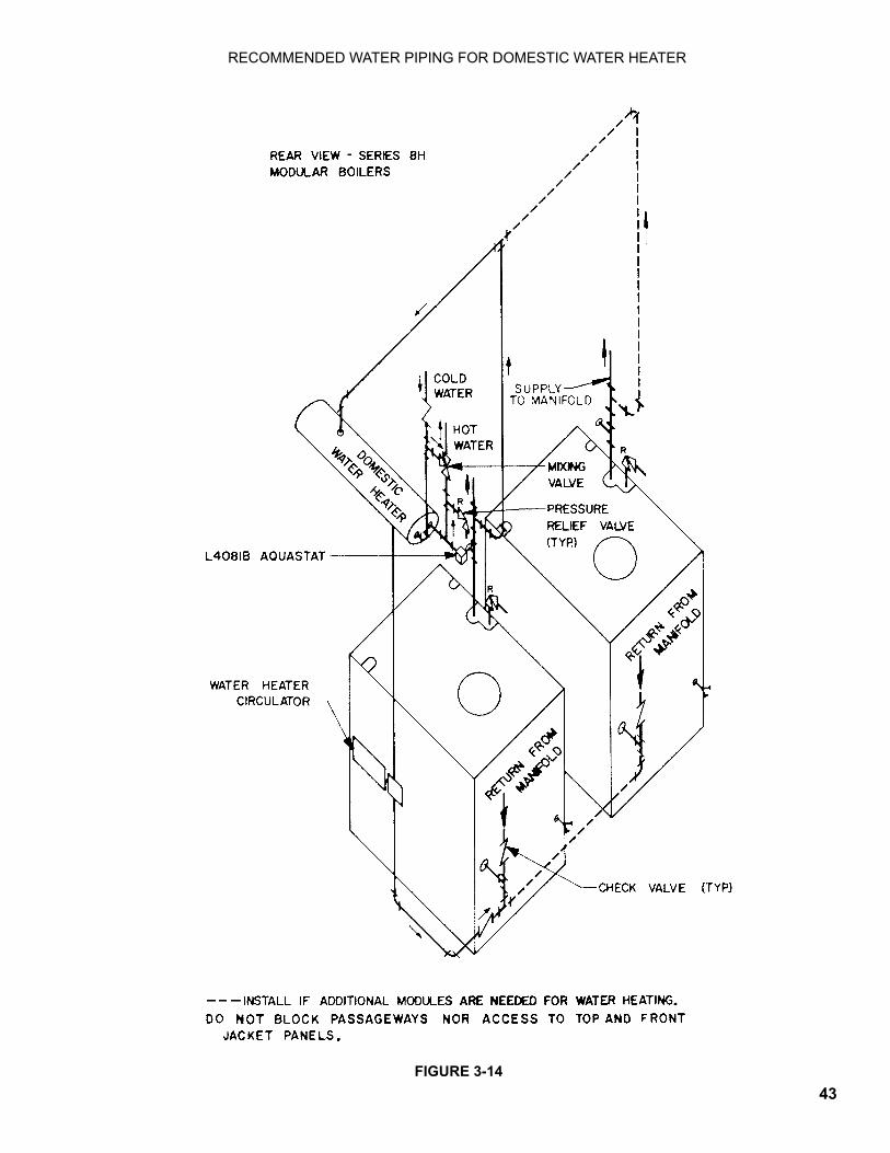
43FIGURE 3-�4
RECOMMENDEDWATERPIPINGFORDOMESTICWATERHEATER
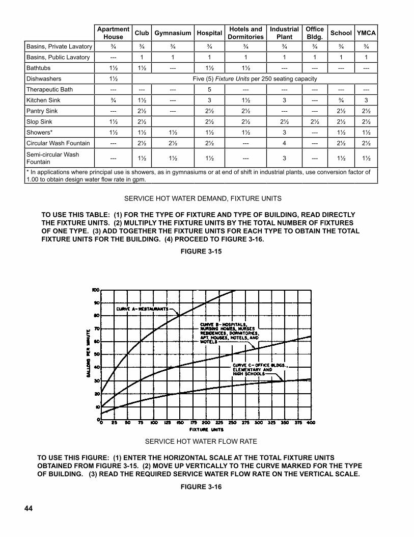
44
SERVICEHOTWATERDEMAND,FIXTUREUNITS
TO USE THIS TABLE: (1) FOR THE TyPE OF FIxTURE AND TyPE OF BUILDING, READ DIREcTLy THE FIxTURE UNITS. (2) MULTIPLy THE FIxTURE UNITS By THE TOTAL NUMBER OF FIxTURES OF ONE TyPE. (3) ADD TOGETHER THE FIxTURE UNITS FOR EAcH TyPE TO OBTAIN THE TOTAL FIxTURE UNITS FOR THE BUILDING. (4) PROcEED TO FIGURE 3-16.
SERVICEHOTWATERFLOWRATE
TO USE THIS FIGURE: (1) ENTER THE HORIzONTAL ScALE AT THE TOTAL FIxTURE UNITS OBTAINED FROM FIGURE 3-15. (2) MOVE UP VERTIcALLy TO THE cURVE MARkED FOR THE TyPE OF BUILDING. (3) READ THE REqUIRED SERVIcE WATER FLOW RATE ON THE VERTIcAL ScALE.
FIGURE 3-�5
FIGURE 3-�6
Apartment House Club Gymnasium Hospital Hotels and
DormitoriesIndustrial
PlantOffice Bldg. School YMCA
Basins,PrivateLavatory ¾ ¾ ¾ ¾ ¾ ¾ ¾ ¾ ¾
Basins,PublicLavatory --- 1 1 1 1 1 1 1 1
Bathtubs 1½ 1½ --- 1½ 1½ --- --- --- ---
Dishwashers 1½ Five(5)Fixture Unitsper250seatingcapacity
TherapeuticBath --- --- --- 5 --- --- --- --- ---
KitchenSink ¾ 1½ --- 3 1½ 3 --- ¾ 3
PantrySink --- 2½ --- 2½ 2½ --- --- 2½ 2½
SlopSink 1½ 2½ 2½ 2½ 2½ 2½ 2½ 2½
Showers* 1½ 1½ 1½ 1½ 1½ 3 --- 1½ 1½
CircularWashFountain --- 2½ 2½ 2½ --- 4 --- 2½ 2½
Semi-circularWashFountain --- 1½ 1½ 1½ --- 3 --- 1½ 1½
*Inapplicationswhereprincipaluseisshowers,asingymnasiumsoratendofshiftinindustrialplants,useconversionfactorof1.00toobtaindesignwaterflowrateingpm.
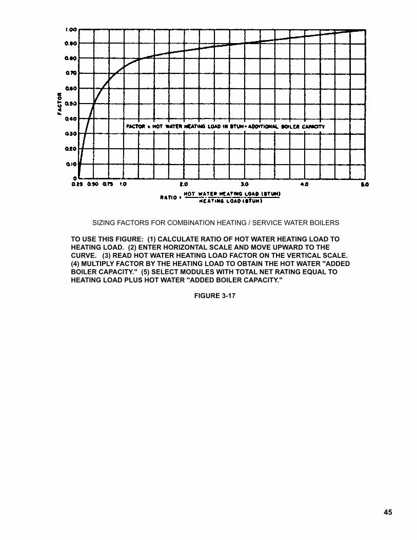
45
SIZINGFACTORSFORCOMBINATIONHEATING/SERVICEWATERBOILERS
TO USE THIS FIGURE: (1) cALcULATE RATIO OF HOT WATER HEATING LOAD TO HEATING LOAD. (2) ENTER HORIzONTAL ScALE AND MOVE UPWARD TO THE cURVE. (3) READ HOT WATER HEATING LOAD FAcTOR ON THE VERTIcAL ScALE. (4) MULTIPLy FAcTOR By THE HEATING LOAD TO OBTAIN THE HOT WATER "ADDED BOILER cAPAcITy." (5) SELEcT MODULES WITH TOTAL NET RATING EqUAL TO HEATING LOAD PLUS HOT WATER "ADDED BOILER CAPACITY."
FIGURE 3-�7
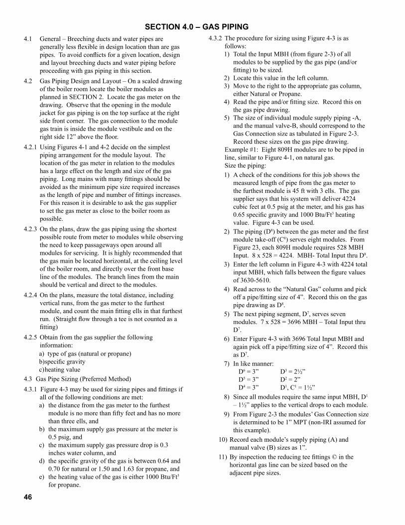
46
4.1 General–Breechingductsandwaterpipesaregenerally less flexible in design location than are gas pipes. To avoid conflicts for a given location, design and layout breeching ducts and water piping before proceedingwithgaspipinginthissection.
4.2 Gas Piping Design and Layout – On a scaled drawing oftheboilerroomlocatetheboilermodulesasplannedinSECTION2.Locatethegasmeteronthedrawing.Observethattheopeninginthemodulejacket for gas piping is on the top surface at the right sidefrontcorner.Thegasconnectiontothemodulegastrainisinsidethemodulevestibuleandontheright side 12” above the floor.
4.2.1UsingFigures4-1and4-2decideonthesimplestpiping arrangement for the module layout. The locationofthegasmeterinrelationtothemoduleshasalargeeffectonthelengthandsizeofthegaspiping. Long mains with many fittings should be avoidedastheminimumpipesizerequiredincreasesas the length of pipe and number of fittings increases. Forthisreasonitisdesirabletoaskthegassuppliertosetthegasmeterasclosetotheboilerroomaspossible.
4.2.3Ontheplans,drawthegaspipingusingtheshortestpossibleroutefrommetertomoduleswhileobservingthe need to keep passageways open around all modules for servicing. It is highly recommended that thegasmainbelocatedhorizontal,attheceilinglevelof the boiler room, and directly over the front base lineofthemodules.Thebranchlinesfromthemainshouldbeverticalanddirecttothemodules.
4.2.4Ontheplans,measurethetotaldistance,includingverticalruns,fromthegasmetertothefurthestmodule, and count the main fitting ells in that furthest run. (Straight flow through a tee is not counted as a fitting)
4.2.5 Obtain from the gas supplier the following information:a) type of gas (natural or propane)b) specific gravityc)heatingvalue
4.3GasPipeSizing(PreferredMethod)4.3.1 Figure 4-3 may be used for sizing pipes and fittings if
all of the following conditions are met:a) thedistancefromthegasmetertothefurthest
module is no more than fifty feet and has no more thanthreeells,and
b) the maximum supply gas pressure at the meter is 0.5 psig, and
c) the maximum supply gas pressure drop is 0.3 incheswatercolumn,and
d) the specific gravity of the gas is between 0.64 and 0.70 for natural or 1.50 and 1.63 for propane, and
e) the heating value of the gas is either 1000 Btu/Ft3forpropane.
SECTION 4.0 – GAS PIPING4.3.2TheprocedureforsizingusingFigure4-3isas
follows:1) Total the Input MBH (from figure 2-3) of all
modules to be supplied by the gas pipe (and/or fitting) to be sized.
2) Locatethisvalueintheleftcolumn.3) Movetotherighttotheappropriategascolumn,
eitherNaturalorPropane.4) Read the pipe and/or fitting size. Record this on
thegaspipedrawing.5) The size of individual module supply piping -A,
andthemanualvalve-B,shouldcorrespondtotheGasConnectionsizeastabulatedinFigure2-3.Recordthesesizesonthegaspipedrawing.
Example #1: Eight 809H modules are to be piped in line,similartoFigure4-1,onnaturalgas.
Size the piping:1) A check of the conditions for this job shows the
measuredlengthofpipefromthegasmetertothe furthest module is 45 ft with 3 ells. The gas supplier says that his system will deliver 4224 cubic feet at 0.5 psig at the meter, and his gas has 0.65 specific gravity and 1000 Btu/Ft3heatingvalue.Figure4-3canbeused.
2) Thepiping(D8) between the gas meter and the first moduletake-off(C8)serveseightmodules.FromFigure 23, each 809H module requires 528 MBH Input. 8 x 528 = 4224. MBH- Total Input thru D8.
3) EntertheleftcolumninFigure4-3with4224totalinput MBH, which falls between the figure values of 3630-5610.
4) Readacrosstothe“NaturalGas”columnandpickoff a pipe/fitting size of 4”. Record this on the gas pipedrawingasD8.
5) The next piping segment, D7,servessevenmodules. 7 x 528 = 3696 MBH – Total Input thru D7.
6) EnterFigure4-3with3696TotalInputMBHandagain pick off a pipe/fitting size of 4”. Record this asD7.
7) In like manner: D6=3” D3 = 2½” D5=3” D2=2” D4=3” D1,C1 = 1½”
8) Since all modules require the same input MBH, D1– 1½” applies to the vertical drops to each module.
9) FromFigure2-3themodules’GasConnectionsizeisdeterminedtobe1”MPT(non-IRIassumedforthisexample).
10) Record each module’s supply piping (A) and manualvalve(B)sizesas1”.
11) By inspection the reducing tee fittings © in the horizontalgaslinecanbesizedbasedonthe adjacent pipe sizes.
47
C8isbetweenD8whichis4”andD7whichisalso4”andfeedsD1 which is 1½”. Hence C8shouldberecorded on the drawing as 4” x 4” x 1½”.
12) In like manner: C7 = 4 x 3 x 1½ C4 = 3 x 2½ x 1½ C6 = 3 x 3 x 1½ C3 = 2½ x 2 x 1½ C5 = 3 x 3 x 1½ C2 = 2 x 1½ x 1½13) Record all pipe and fitting sizes on the gas pipe
drawingforreferenceduringinstallation.4.4 Gas Pipe Sizing (Alternate Method)4.4.1 IfalloftheconditionsforusingFigure4-3arenot
met,thefollowingproceduremustbeusedtosizegaspiping:1) Determinethetotalequivalentlengthofpipefrom
the meter to the furthest module by adding to the measuredlengththeequivalentlengthofeachfitting from Figure 4-4. (Straight thru flow through a tee is not considered a fitting).
2) Determinetheactualcubicfeetofgastobecarried by the main segment by dividing the BTU requirement by the heating value of the gas.
3) Determine the equivalent cubic feet of .60 specific gravity gas by multiplying the actual cubic feet from 2) above by the appropriate specific gravity multiplierfromFigure4-6.
4) Enter Figure 4-5 under column for the total equivalentlengthofpipeasfoundin1)above.
5) Read down until finding a number equal to or greaterthantheequivalentcubicfeetfrom3)above, which the main segment is required to carry.
6) Readacrosstothelefthandcolumnandpickofftheminimumpipesizerequired.
Example #2: Eight 809H modules are to be piped in line with propane from a tank source 115 feet from the furthest module and 8 ells are in the supply line. The propane to be used has a specific gravity of 1.40 and a heating value of 2420 Btu/Ft3. Size the piping:a) To the measured length of 115’ add the equivalent
length of 8 ells x 10.1 Ft/Ell for a total equivalent of 195.8 Ft. (The factor of 10.1 comes from Figure 4-4underthecolumnforellsatanestimated4”mainsize.)
b) TheactualcubicfeetrequiredinmainD8is 8 (modules) x 528,000 (Btu/809H) = 1745 Ft3/Hr 2420 (BTU/Ft3)
Inalikemannertheactualcubicfeetrequiredintheremaining main segments are found to be: FlowD7 = 7 x 528,000 + 2420 = 1527 Ft3/Hr FlowD6 = 6 x 528,000 + 2420 = 1309 Ft3/Hr FlowD5 = 5 x 528,000 + 2420 = 1091 Ft3/Hr FlowD4 = 4 x 528,000 + 2420 = 873 Ft3/Hr FlowD3 = 3 x 528,000 + 2420 = 655 Ft3/Hr FlowD2 = 2 x 528,000 + 2420 = 436 Ft3/Hr FlowD1 = 1 x 528,000 + 2420 = 218 Ft3/Hr
c) Enter figure 4-6 at a specific gravity of 1.40 and note the multiplier of 1.3. Tabulate equivalent flow rates for each pipe segment as follows:
Equiv. Flow D8 = 1745 x 1.53 = 2671 Ft3/Hr Equiv. Flow D7 = 1527 x 1.53 = 2337 Ft3/Hr Equiv. Flow D6 = 1309 x 1.53 = 2003 Ft3/Hr Equiv. Flow D5 = 1091 x 1.53 = 1669 Ft3/Hr Equiv. Flow D4 = 873 x 1.53 = 1335 Ft3/Hr Equiv. Flow D3 = 655 x 1.53 = 1001 Ft3/Hr Equiv. Flow D2 = 436 x 1.53 = 668 Ft3/Hr Equiv. Flow D1 = 218 x 1.53 = 334 Ft3/Hrd) Enter Figure 4-5 from the top at column marked
200 Ft. of pipe. The length found in a) above was 195.8 Ft. which is between column marked 175 and 200 Ft. Use next larger of 200 Ft.
e) Read down until finding a number equal to or greater than the equivalent cubic foot flow requirementfoundinc)above.
f) Readacrosstothelefthandcolumnandpickoffthe following required minimum pipe sizes:
SizeD8=4” SizeD7=4” SizeD6=4” SizeD5=3” SizeD4=3” SizeD3=3” SizeD2 = 2½” SizeD1=2”g) D1=2”becomestheverticalriserfromeachofthe
modulestotheoverheadhorizontalmain.h) Markallpipesizesontheplanforreferenceduring
installation.4.5 Gas Pipe Installation With modules fully assembled, including jackets,
install gas supply piping in accordance with the current edition of “National Fuel Gas Code” (ANSI Z223.1)andallrequirementsofthegassupplierandmunicipality.
4.5.1 Please consider the serviceman who must periodically clean and adjust the modules, and repair accessories. Do not block passageways with piping. Do not block access panels on the module jackets.
4.5.2 Material – Use only Schedule 40 black iron pipe. Make sure all threads are fully formed and free of burrs. Threaded joints should be sealed with an approvedcompoundtopreventleaks.
4.5.3 Traps – Install a trap similar to that shown in Figure 4-8 at the low end of the vertical run to each module.
4.5.4 Supports – Pipe supports should be installed according to Figure 4-7. Supports should encircle the pipe at ceilinglevelbutallowmovementforexpansionofthepiping.Theweightofthegaspipingmustnotbeplaceduponthemodulegasconnection.
4.5.5 Grounding – Gas piping must be grounded. If any non-conductive fittings are used they must be bridged

48
with an appropriately sized ground wire. Particular attention should be given to a propane system with above ground tank(s). Such tank(s) must be externally grounded.
4.5.6 Leak Testing – If the gas lines have been designed accordingtoprecedingsectionsofthismanual,theoperating gas pressure will be 0.5 psig. Under such pressure, fuel gas may be used for leak testing. On eachmodule,turnthemanualportionofcombinationvalve to off position before applying gas pressure. Immediately after applying gas pressure, apply leak checksolutiontoallgaspipingandobservepipingforleaks. Repair any leaks found and retest piping. If the gassupplierrequiresleaktestingatpressureshigherthan 0.5 psig, or with inert gas, follow that required procedureinfull.
4.6 GasPipingMaintenance–Pipingshouldbeinspectedannually or after any extended shut down period. If the normal operating gas pressure is 0.5 psig or less, fuelgascanbeusedforleakdetectionasdescribedin4.5.6 above.
4.6.1 Any pipe or fitting showing unusual rust or corrosion shouldbereplaced.
4.6.2 Gaspipingshouldnotbeusedasanelectricalconductor. Relocate any electrical circuit which is foundtobeusingthegaspipingasaconductor.
Note: Many municipalities allow light weight, low voltage,wellinsulatedelectricalwiretobesupportedonthegaspipingwithapprovednon-conductivefasteners.
4.6.3 Gas piping should not be used to support any other pipe or heavy object. Find other means to support any such heavy object.
4.6.4 Traps should be cleaned at least once every two years. Turn off gas supply, remove cap below tee, as shown in Figure 4-8, and clean out all moisture and foreignmaterial.Replacecapandcheckforleaksasdescribed in 4.5.6 above.
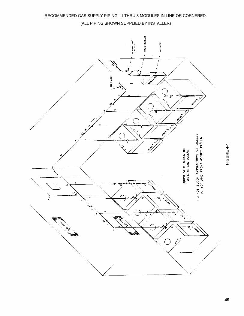
4�
FIG
UR
E 4-
�
RECOMMENDEDGASSUPPLYPIPING-1THRU8MODULESINLINEORCORNERED.
(ALLPIPINGSHOWNSUPPLIEDBYINSTALLER)
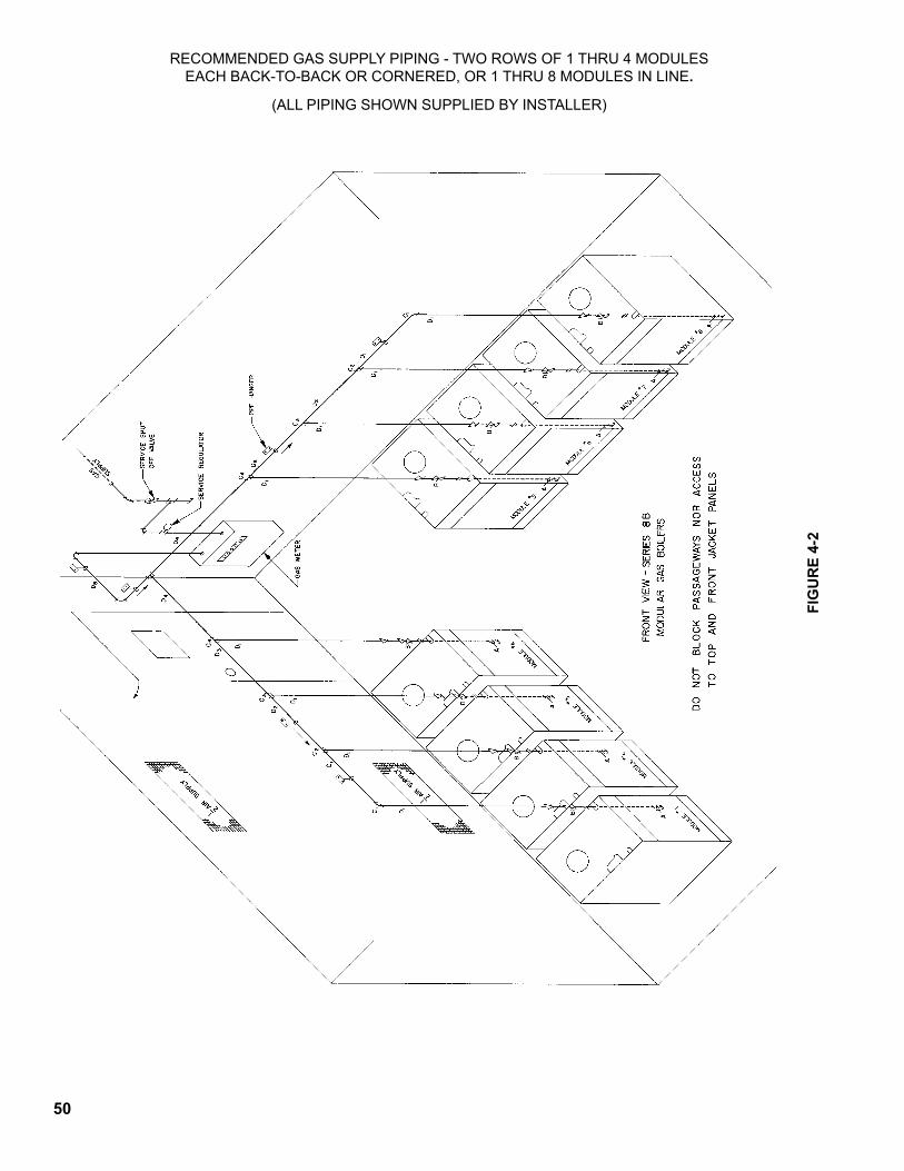
50
RECOMMENDEDGASSUPPLYPIPING-TWOROWSOF1THRU4MODULESEACHBACK-TO-BACKORCORNERED,OR1THRU8MODULESINLINE.
(ALLPIPINGSHOWNSUPPLIEDBYINSTALLER)
FIG
UR
E 4-
2
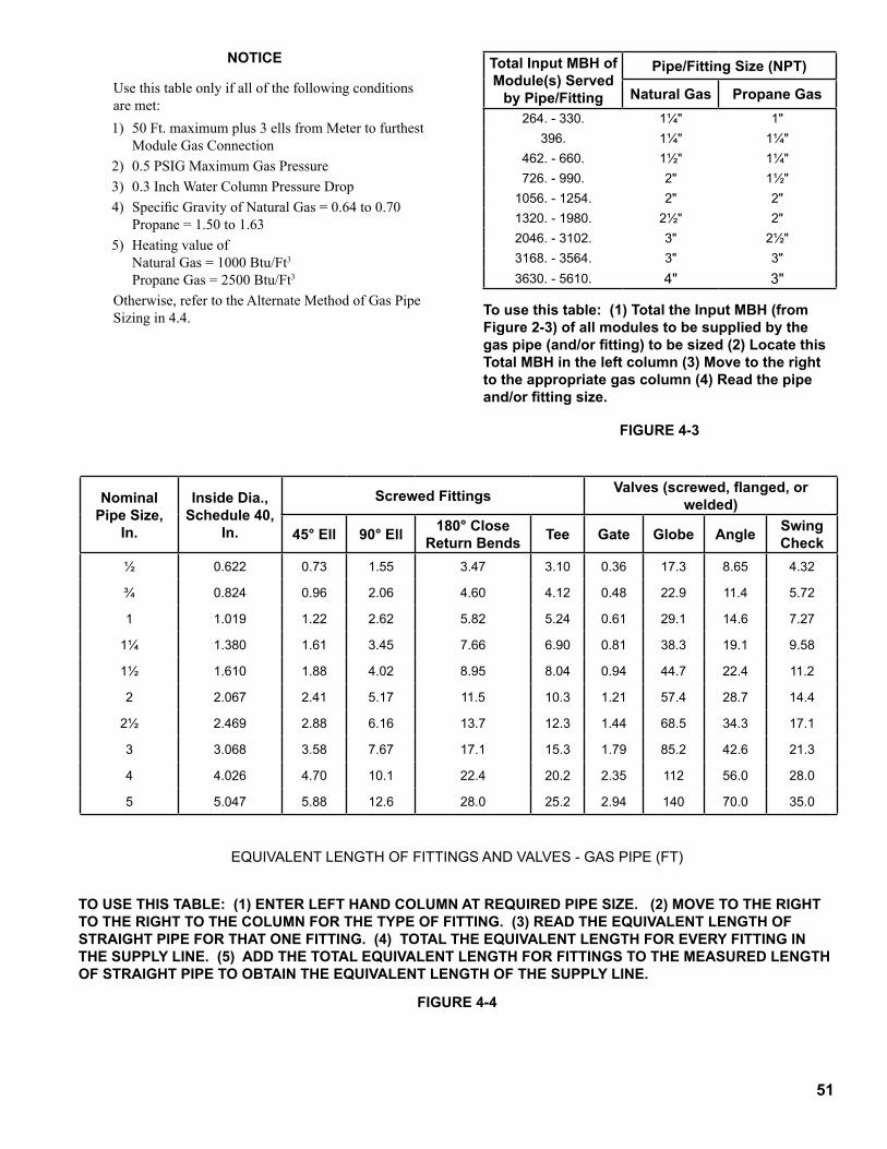
5�
NOTICE
Use this table only if all of the following conditions are met:1) 50 Ft. maximum plus 3 ells from Meter to furthest
ModuleGasConnection2) 0.5 PSIG Maximum Gas Pressure3) 0.3 Inch Water Column Pressure Drop4) Specific Gravity of Natural Gas = 0.64 to 0.70
Propane = 1.50 to 1.635) Heating value of Natural Gas = 1000 Btu/Ft3
Propane Gas = 2500 Btu/Ft3
Otherwise, refer to the Alternate Method of Gas Pipe Sizingin4.4. To use this table: (1) Total the Input MBH (from
Figure 2-3) of all modules to be supplied by the gas pipe (and/or fitting) to be sized (2) Locate this Total MBH in the left column (3) Move to the right to the appropriate gas column (4) Read the pipe and/or fitting size.
FIGURE 4-3
EQUIVALENTLENGTHOFFITTINGSANDVALVES-GASPIPE(FT)
TO USE THIS TABLE: (1) ENTER LEFT HAND cOLUMN AT REqUIRED PIPE SIzE. (2) MOVE TO THE RIGHT TO THE RIGHT TO THE cOLUMN FOR THE TyPE OF FITTING. (3) READ THE EqUIVALENT LENGTH OF STRAIGHT PIPE FOR THAT ONE FITTING. (4) TOTAL THE EqUIVALENT LENGTH FOR EVERy FITTING IN THE SUPPLy LINE. (5) ADD THE TOTAL EqUIVALENT LENGTH FOR FITTINGS TO THE MEASURED LENGTH OF STRAIGHT PIPE TO OBTAIN THE EQUIVALENT LENGTH OF THE SUPPLY LINE.
FIGURE 4-4
Total Input MBH of Module(s) Served
by Pipe/Fitting
Pipe/Fitting Size (NPT)
Natural Gas Propane Gas264.-330. 1¼" 1"
396. 1¼" 1¼"462.-660. 1½" 1¼"726.-990. 2" 1½"1056.-1254. 2" 2"1320.-1980. 2½" 2"2046.-3102. 3" 2½"3168.-3564. 3" 3"3630.-5610. 4" 3"
Nominal Pipe Size,
In.
Inside Dia., Schedule 40,
In.
Screwed Fittings Valves (screwed, flanged, or welded)
45° Ell 90° Ell 180° close Return Bends Tee Gate Globe Angle Swing
Check½ 0.622 0.73 1.55 3.47 3.10 0.36 17.3 8.65 4.32
¾ 0.824 0.96 2.06 4.60 4.12 0.48 22.9 11.4 5.72
1 1.019 1.22 2.62 5.82 5.24 0.61 29.1 14.6 7.27
1¼ 1.380 1.61 3.45 7.66 6.90 0.81 38.3 19.1 9.58
1½ 1.610 1.88 4.02 8.95 8.04 0.94 44.7 22.4 11.2
2 2.067 2.41 5.17 11.5 10.3 1.21 57.4 28.7 14.4
2½ 2.469 2.88 6.16 13.7 12.3 1.44 68.5 34.3 17.1
3 3.068 3.58 7.67 17.1 15.3 1.79 85.2 42.6 21.3
4 4.026 4.70 10.1 22.4 20.2 2.35 112 56.0 28.0
5 5.047 5.88 12.6 28.0 25.2 2.94 140 70.0 35.0
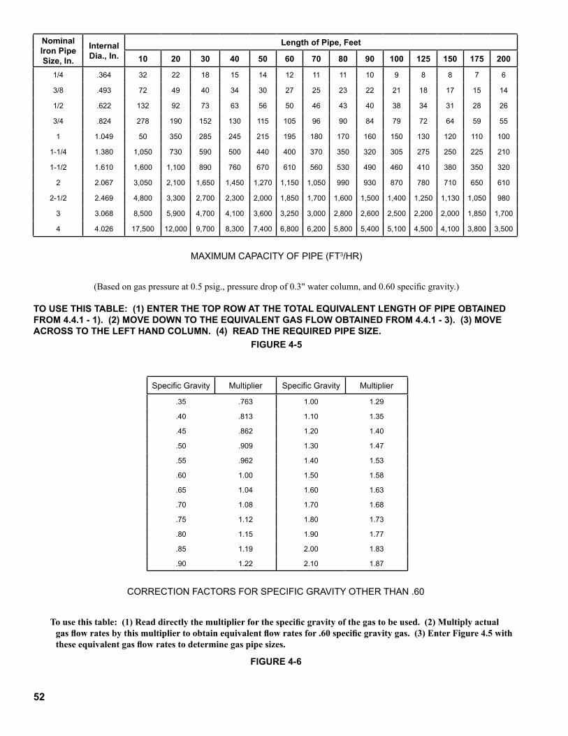
52
MAXIMUMCAPACITYOFPIPE(FT3/HR)
(Based on gas pressure at 0.5 psig., pressure drop of 0.3" water column, and 0.60 specific gravity.)
TO USE THIS TABLE: (1) ENTER THE TOP ROW AT THE TOTAL EqUIVALENT LENGTH OF PIPE OBTAINED FROM 4.4.1 - 1). (2) MOVE DOWN TO THE EqUIVALENT GAS FLOW OBTAINED FROM 4.4.1 - 3). (3) MOVE AcROSS TO THE LEFT HAND cOLUMN. (4) READ THE REqUIRED PIPE SIzE.
CORRECTIONFACTORSFORSPECIFICGRAVITYOTHERTHAN.60
To use this table: (1) Read directly the multiplier for the specific gravity of the gas to be used. (2) Multiply actual gas flow rates by this multiplier to obtain equivalent flow rates for .60 specific gravity gas. (3) Enter Figure 4.5 with these equivalent gas flow rates to determine gas pipe sizes.
FIGURE 4-5
FIGURE 4-6
Nominal Iron Pipe Size, In.
Internal Dia., In.
Length of Pipe, Feet
�0 20 30 40 50 60 70 80 �0 �00 �25 �50 �75 200
1/4 .364 32 22 18 15 14 12 11 11 10 9 8 8 7 6
3/8 .493 72 49 40 34 30 27 25 23 22 21 18 17 15 14
1/2 .622 132 92 73 63 56 50 46 43 40 38 34 31 28 26
3/4 .824 278 190 152 130 115 105 96 90 84 79 72 64 59 55
1 1.049 50 350 285 245 215 195 180 170 160 150 130 120 110 100
1-1/4 1.380 1,050 730 590 500 440 400 370 350 320 305 275 250 225 210
1-1/2 1.610 1,600 1,100 890 760 670 610 560 530 490 460 410 380 350 320
2 2.067 3,050 2,100 1,650 1,450 1,270 1,150 1,050 990 930 870 780 710 650 610
2-1/2 2.469 4,800 3,300 2,700 2,300 2,000 1,850 1,700 1,600 1,500 1,400 1,250 1,130 1,050 980
3 3.068 8,500 5,900 4,700 4,100 3,600 3,250 3,000 2,800 2,600 2,500 2,200 2,000 1,850 1,700
4 4.026 17,500 12,000 9,700 8,300 7,400 6,800 6,200 5,800 5,400 5,100 4,500 4,100 3,800 3,500
SpecificGravity Multiplier SpecificGravity Multiplier
.35 .763 1.00 1.29
.40 .813 1.10 1.35
.45 .862 1.20 1.40
.50 .909 1.30 1.47
.55 .962 1.40 1.53
.60 1.00 1.50 1.58
.65 1.04 1.60 1.63
.70 1.08 1.70 1.68
.75 1.12 1.80 1.73
.80 1.15 1.90 1.77
.85 1.19 2.00 1.83
.90 1.22 2.10 1.87
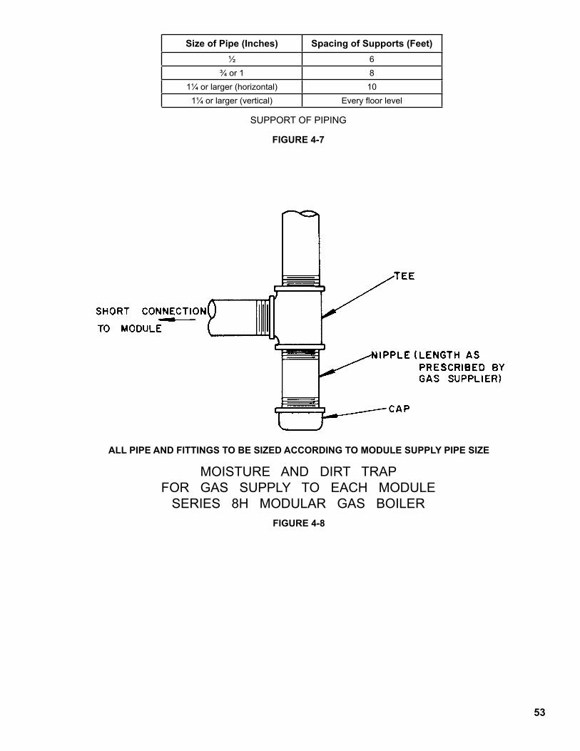
53
SUPPORTOFPIPING
FIGURE 4-7
MOISTUREANDDIRTTRAPFORGASSUPPLYTOEACHMODULESERIES8HMODULARGASBOILER
ALL PIPE AND FITTINGS TO BE SIZED ACCORDING TO MODULE SUPPLY PIPE SIZE
FIGURE 4-8
Size of Pipe (Inches) Spacing of Supports (Feet)½ 6
¾or1 81¼orlarger(horizontal) 101¼orlarger(vertical) Everyfloorlevel
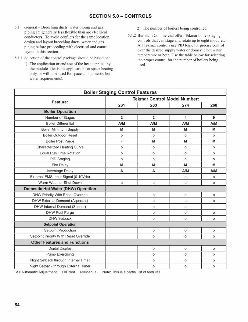
54
SECTION 5.0 – CONTROLS
5.1 General–Breechingducts,waterpipingandgaspiping are generally less flexible than are electrical conductors. To avoid conflicts for the same location, design and layout breeching ducts, water and gas piping before proceeding with electrical and control layoutinthissection.
5.1.1 Selection of the control package should be based on:1) The application or end use of the heat supplied by
the modules (ie: is the application for space heating only, or will it be used for space and domestic hot water requirements).
2) The number of boilers being controlled.
5.1.2 Burnham Commercial offers Tekmar boiler staging controls that can stage and rotate up to eight modules. All Tekmar controls use PID logic for precise control over the desired supply water or domestic hot water temperature or both. Use the table below for selecting the proper control for the number of boilers being used.
Boiler Staging Control Features
Feature:Tekmar Control Model Number:
261 263 274 268Boiler OperationNumber of Stages 2 2 4 9Boiler Differential A/M A/M A/M A/M
Boiler Minimum Supply M M M MBoiler Outdoor Reset o o o o
Boiler Post Purge F M M MCharacterized Heating Curve o o o o
Equal Run Time Rotation o o o oPID Staging o o o oFire Delay M M M M
Interstage Delay A A A/M A/MExternal EMS Input Signal (0-10Vdc) o o
Warm Weather Shut Down o o o o
Domestic Hot Water (DHW) OperationDHW Priority With Reset Override o o oDHW External Demand (Aquastat) o o oDHW Internal Demand (Sensor) o o
DHW Post Purge o o oDHW Setback o o o
Setpoint OperationSetpoint Production o o o
Setpoint Priority With Reset Override o o o
Other Features and FunctionsDigital Display o o o
Pump Exercising o o oNight Setback through Internal Timer o o oNight Setback through External Timer o o o
A= Automatic Adjustment F=Fixed M=Manual Note: This is a partial list of features
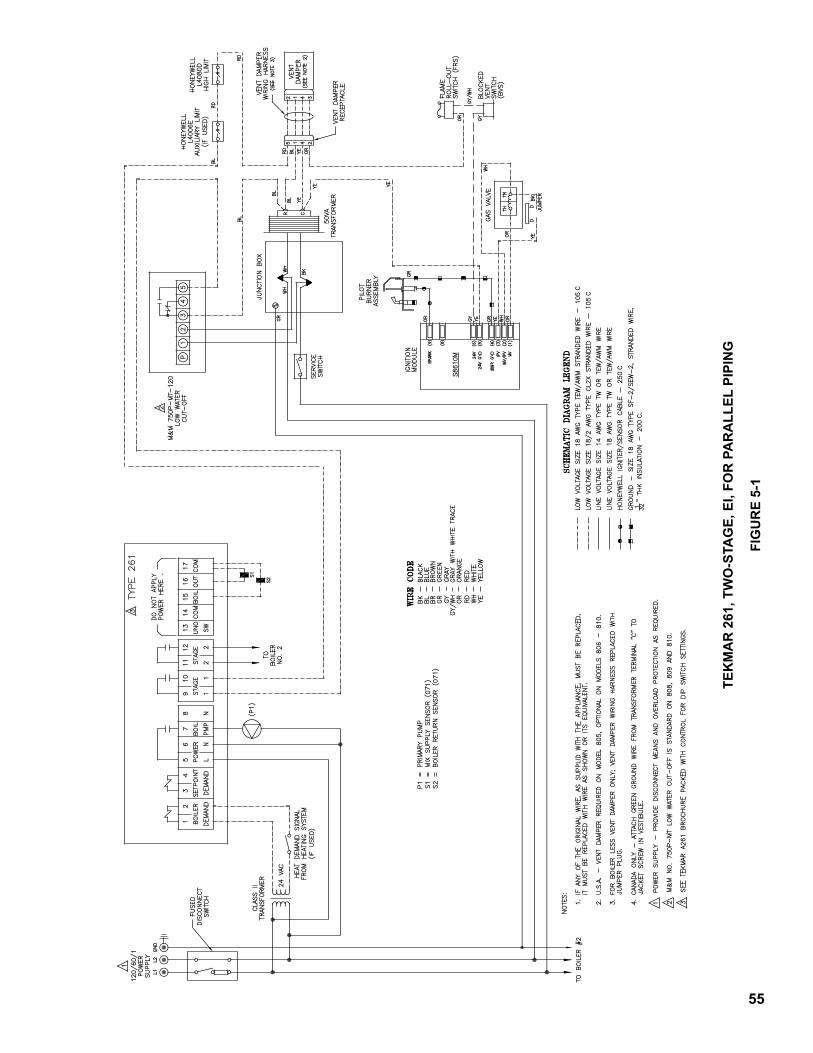
55
TEk
MA
R 2
61, T
WO
-STA
GE,
EI,
FOR
PA
RA
LLEL
PIP
ING
FIG
UR
E 5-
�
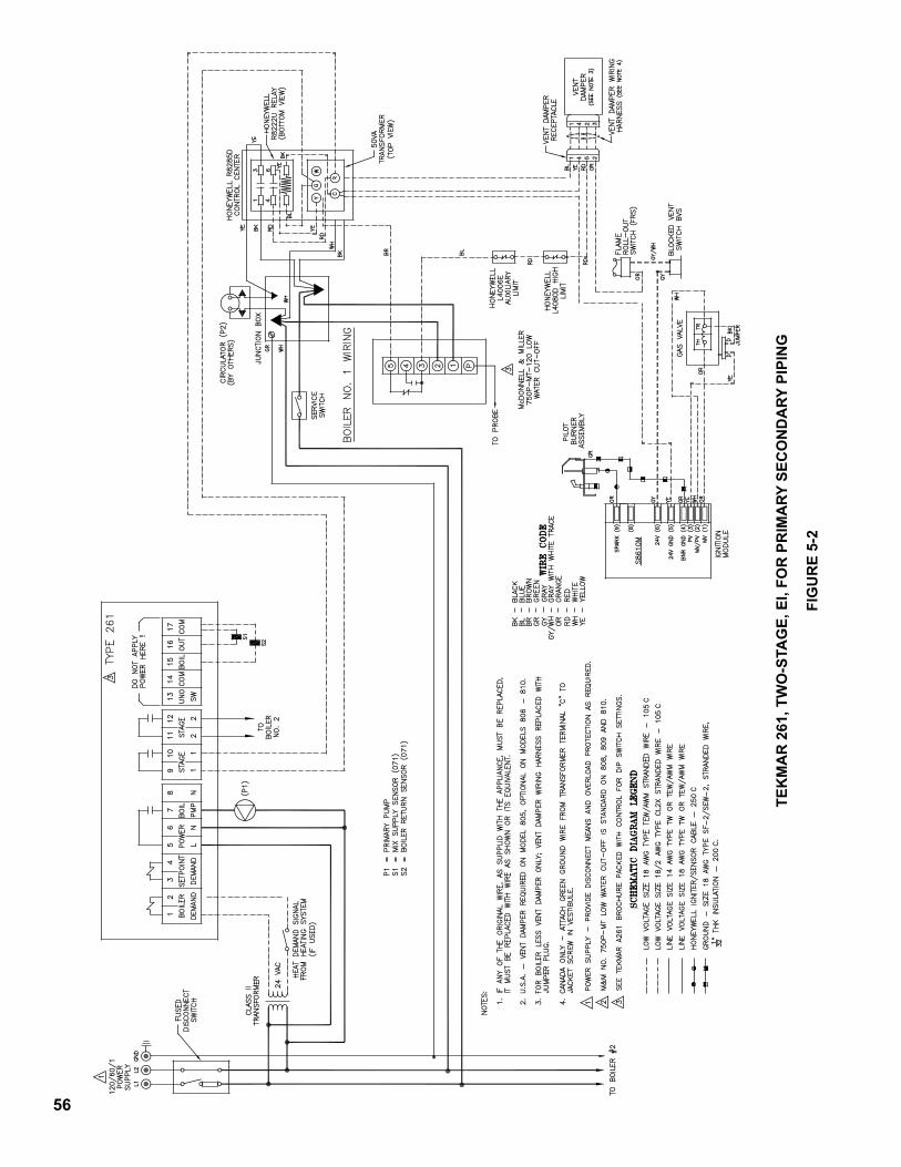
56
TEk
MA
R 2
61, T
WO
-STA
GE,
EI,
FOR
PR
IMA
Ry S
EcO
ND
ARy
PIP
ING
FIG
UR
E 5-
2
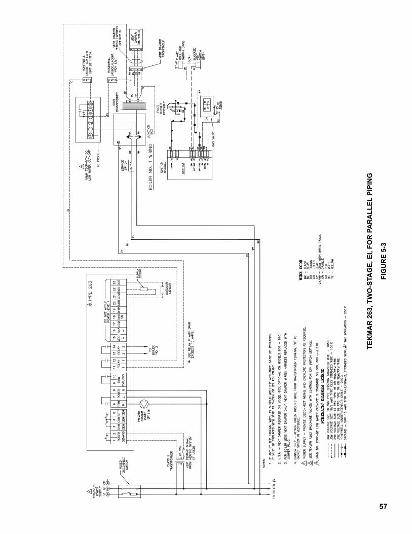
57
TEk
MA
R 2
63, T
WO
-STA
GE,
EI,
FOR
PA
RA
LLEL
PIP
ING
FIG
UR
E 5-
3
58
TEk
MA
R 2
63, T
WO
-STA
GE,
EI,
FOR
PR
IMA
Ry S
EcO
ND
ARy
PIP
ING
FIG
UR
E 5-
4
5�
TEk
MA
R 2
74, F
OU
R-S
TAG
E, E
I, FO
R P
AR
ALL
EL P
IPIN
G
FIG
UR
E 5-
5
60
TEk
MA
R 2
74, F
OU
R-S
TAG
E, E
I, FO
R P
RIM
ARy
SEc
ON
DA
Ry P
IPIN
G
FIG
UR
E 5-
6
6�
TEk
MA
R 2
68, E
IGH
T-ST
AG
E, E
I, FO
R P
AR
ALL
EL P
IPIN
G
FIG
UR
E 5-
7
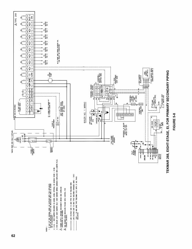
62
TEk
MA
R 2
68, E
IGH
T-ST
AG
E, E
I, FO
R P
RIM
ARy
SEc
ON
DA
Ry P
IPIN
G
FIG
UR
E 5-
8
63
SECTION 6.0START-UP AND SERVICE
WARNING - BEFORE INSTALLATION OF THE BOILER IS CONSIDERED COMPLETE THE OPERATION OF THE BOILER CONTROLS SHOULD ALL BE CHECKED, PARTICULARLY THE LOW WATER CUT-OFF AND THE HIGH LIMIT CONTROLS.6.1 FILL ENTIRE HEATING SYSTEM WITH WATER
and vent air from system. Use the following procedure on a system equipped with zone valves.1) Closeallbutonezonevalve.2) Opendrainvalvesonboilers.3) Open fill valve.4) Closepurgevalve.5) Open relief valves on boilers.6) Allow water to run out of drain valve until zone
has been purged of air and filled with water.7) Open zone valve to the second zone to be purged,
then close the first. Repeat this step until all zones have been purged but always have one zone open. At completion open all zone valves.
8) Close drain valve.9) When water discharges from relief valves, release
theleveronthetopofthereliefvalves,allowingthemtoclose.
10) Continue filling the system until the pressure gauge reads 12 psi. Close fill valve.
11) Openpurgevalve.12) Start system circulator.
6.2 TEST GAS PIPING. Test main and pilot gas piping atboilerforleaksatallpipingconnectionsandvalves.Refer to 4.5.6.
6.3 PURGE GAS PIPING OF AIR1) Disconnectelectricservicetoboiler.2) Turncontrolknobonallmodules'combinationgas
valvestooffposition.3) Openvalveonmaingaslineatmeter.4) StartingwithModule#1disconnectpilottubing
fromoutletsideofcombinationgasvalve.DepressControl Knob slightly and turn to "Pilot" position. Depress Knob fully and hold until gas issues from disconnected fitting. Release Knob and reconnect pilottubing.Turncontrolknobtooff.
5) Repeat (4) for each module in sequence.6.4 Makesurethatpilottubinghasbeenreconnected.
Wait five minutes then proceed "To Light" in accordancewithboileroperatinginstructionsattached to the boiler jacket. On boilers equipped withstandingpilots,lightthepilotofeachboilerinsequence.
6.5 CHECK GAS INPUT rate to each boiler separately. InputratemustnotexceedthatshownonRatingPlate.For propane gas adjust regulator for a burner manifold pressure of eleven (11.0) inches water column.
Fornaturalgas,checkinputrateshownonboilerrating plate as follows:1) Consult local gas company for heating value of gas
(BTU/Cu. Ft.).2) Setlimitandoperatingcontrolhighenoughso
boilerwillnotshutoffwhilecheckinginputrate.3) All other gas burning appliances served by meter
should be turned off temporarily while checking inputrate.
4) Check manifold pressure at 1/8" tapping on burner manifold. Pressure should be approximately 3½" water column for natural gas. Adjustment of gas pressure can be made by turning regulator adjusting screw counterclockwise to decrease manifoldpressure(gasrate)orclockwisetoincrease. Adjustment of Regulator must be within limitations set forth by Gas Supplier.
If necessary to increase or decrease manifold pressure more than 0.3" water for natural gas to provide rated input, remove orifice plugs installed in burner manifold and:
a) Increase orifices one (1) drill size larger to reduce manifoldpressuretothatrecommended,or
b) Replace orifices with one (1) drill size smaller to raisemanifoldpressuretothatrecommended.
c) Reinstall orifice plugs and recheck input rate.5) After adjusting manifold pressure to that
recommended, make a final check on input by clocking the gas meter. Only the gas boiler should beinoperation(makesurethatallothergasappliancesconnectedtothesamemeterarenotoperating).Checkthegasconsumptionindicatedby the gas meter for three minutes for conformity to that required and as determined by the following formula:
GasInput,Cu.Ft.per3minutes= (Input, Btu/hr. (Heating Value of gas, Btu/Cu. Ft.) x 20 NOTE: In the above formula, (Input, Btu/hr.) is
thatshownontheBoilerratingplate,andheatingvalue of gas, Btu/Cu. Ft., must be obtained from the local gas company.
I.E. Input for 5-Section Boiler is 264,000 Btu/hr. Heating value of gas is 1,000 Btu/cu. ft.
Therefore: 264,000 = 264,000 = 13.2 cu. ft./3 min. 1,000 x 20 20,0006) Returnallcontrolsettingstotheirnormal
positions.
64
6.6 ADJUST AIR SHUTTERS on Main Burners by looseningshutterlockscrewandclosingthemuntilyellow tips appear on flames, then open shutters slowly until clearly defined inner cones may be seen. Tightenscrewstoholdtheairshuttersinthisposition.
6.7 SEQUENCE OF CONTROLS See Section 5.0 for the sequence of controls that
applies to the system installed.
6.8 CLEANING BOILER FLUES AND BURNERS Boiler flues should be inspected annually and
burners should be cleaned annually. The proper proceduresforthismaintenance,includingremovaland reinstallation of canopy, burners, and pilot assemblies,aredetailedanddiagrammedinthe"INSTALLATION, OPERATING AND SERVICE INSTRUCTIONS" manual supplied with each 8H SeriesBoiler.
Ix. Repair Parts
All Series 8H repair parts may be obtained through your local Burnham Wholesale Distributor. Should you require assis-tance in locating a Burnham Distributor in your area, or have questions regarding the availability of Burnham products or repair parts, please contact Burnham Customer Service at (717) 481-8400 or Fax (717) 481-8408.
HeatingContractor InstallationDate
Address PhoneNumber
Forserviceorrepairstoboiler,callourheatingcontractor.Whenseekinginformationonboiler,provideBoiler,provideBoilerModelNumberandSerialNumberasshownonRatingLabel.
BoilerModelNumber BoilerSerialNumber_8_____-____ 6________8_____-____ 6________8_____-____ 6________8_____-____ 6________8_____-____ 6________8_____-____ 6________8_____-____ 6________8_____-____ 6_______

65
Important Product Safety InformationRefractory Ceramic Fiber Product
Warning:TheRepairPartslistdesignatespartsthatcontainrefractoryceramicfibers(RCF).RCFhasbeenclassifiedasapossiblehumancarcinogen.Whenexposedtotemperaturesabout1805°F,suchasduringdirectflamecontact,RCFchangesintocrystallinesilica,aknowncarcinogen.Whendisturbedasaresultofservicingorrepair,thesesubstancesbecomeairborneand,ifinhaled,maybehazardoustoyourhealth.
AVOIDBreathingFiberParticulatesandDust
Precautionary Measures:DonotremoveorreplaceRCFpartsorattemptanyserviceorrepairworkinvolvingRCFwithoutwearingthefollowingprotectivegear:
1.ANationalInstituteforOccupationalSafetyandHealth(NIOSH)approvedrespirator
2.Longsleeved,loosefittingclothing3.Gloves4.EyeProtection
• Takestepstoassureadequateventilation.• Washallexposedbodyareasgentlywithsoapandwateraftercontact.• Washworkclothesseparatelyfromotherlaundryandrinsewashing
machineafterusetoavoidcontaminatingotherclothes.• DiscardusedRCFcomponentsbysealinginanairtightplasticbag.RCF
andcrystallinesilicaarenotclassifiedashazardouswastesintheUnitedStatesandCanada.
First Aid Procedures:• Ifcontactwitheyes:Flushwithwaterforatleast15minutes.Seek
immediatemedicalattentionifirritationpersists.• Ifcontactwithskin:Washaffectedareagentlywithsoapandwater.
Seekimmediatemedicalattentionifirritationpersists.• Ifbreathingdifficultydevelops:Leavetheareaandmovetoalocation
withcleanfreshair.Seekimmediatemedicalattentionifbreathingdifficultiespersist.
• Ingestion:Donotinducevomiting.Drinkplentyofwater.Seekimmediatemedicalattention.

66
SERVICE RECORDDATE SERVICEPERFORMED

67
SERVICE RECORDDATE SERVICEPERFORMED

68