Multiple description transform coded transmission over ...
37
Accepted Manuscript Multiple description transform coded transmission over OFDM broadcast channels Ashwani Sharma, Swades De, Hari M. Gupta, Ranjan Gangopadhyay PII: S1874-4907(14)00047-0 DOI: http://dx.doi.org/10.1016/j.phycom.2014.05.001 Reference: PHYCOM 255 To appear in: Physical Communication Received date: 31 December 2012 Revised date: 8 May 2014 Accepted date: 9 May 2014 Please cite this article as: A. Sharma, S. De, H.M. Gupta, R. Gangopadhyay, Multiple description transform coded transmission over OFDM broadcast channels, Physical Communication (2014), http://dx.doi.org/10.1016/j.phycom.2014.05.001 This is a PDF file of an unedited manuscript that has been accepted for publication. As a service to our customers we are providing this early version of the manuscript. The manuscript will undergo copyediting, typesetting, and review of the resulting proof before it is published in its final form. Please note that during the production process errors may be discovered which could affect the content, and all legal disclaimers that apply to the journal pertain.
Transcript of Multiple description transform coded transmission over ...

Accepted Manuscript
Multiple description transform coded transmission over OFDMbroadcast channels
Ashwani Sharma, Swades De, Hari M. Gupta, Ranjan Gangopadhyay
PII: S1874-4907(14)00047-0DOI: http://dx.doi.org/10.1016/j.phycom.2014.05.001Reference: PHYCOM 255
To appear in: Physical Communication
Received date: 31 December 2012Revised date: 8 May 2014Accepted date: 9 May 2014
Please cite this article as: A. Sharma, S. De, H.M. Gupta, R. Gangopadhyay, Multipledescription transform coded transmission over OFDM broadcast channels, PhysicalCommunication (2014), http://dx.doi.org/10.1016/j.phycom.2014.05.001
This is a PDF file of an unedited manuscript that has been accepted for publication. As aservice to our customers we are providing this early version of the manuscript. The manuscriptwill undergo copyediting, typesetting, and review of the resulting proof before it is published inits final form. Please note that during the production process errors may be discovered whichcould affect the content, and all legal disclaimers that apply to the journal pertain.

1 2 3 4 5 6 7 8 9 10 11 12 13 14 15 16 17 18 19 20 21 22 23 24 25 26 27 28 29 30 31 32 33 34 35 36 37 38 39 40 41 42 43 44 45 46 47 48 49 50 51 52 53 54 55 56 57 58 59 60 61 62 63 64 65
Multiple Description Transform Coded Transmission over OFDMBroadcast Channels
Ashwani Sharmaa, Swades Deb,∗, Hari M. Guptab, Ranjan Gangopadhyayc
aMobility Group, DuestoTech, University of Duesto, Bilbao, SpainbElectrical Engineering Dept. and Bharti School of Telecom, Indian Institute of Technology Delhi, New Delhi, India
cThe LNM Institute of Information Technology, Jaipur, India
Abstract
We consider image transmission using multiple description transform coding (MDTC) over or-
thogonal frequency division multiplexed (OFDM) wireless broadcast channels, where the system
may not have any feedback on channel gains. We investigate the redundancy allocation in MDTC-
OFDM system, physical layer frequency diversity, and decoding strategies to maximize the quality
of reconstruction. Via mathematical analysis, supported by MATLAB simulations, we show that,
error resilience of the descriptions can be increased by suitable assignment of coding redundancy
in the transform modules at the source, which can be further optimized if the channel character-
istics are known at the transmitter. Additionally, the relative performance of the MDTC-OFDM
system is studied with respect to a competitive approach, called forward error correction based
multiple description coding (MDC) over OFDM, where we show that, for the same redundancy
assignment, the MDTC based system performs better under harsh channel conditions.
Keywords: Multiple description transform coding; source coding redundancy; MDTC-OFDM
system; feedback-less broadcast channel; frequency diversity; MDTC estimation
1. Introduction
There are three types of coding normally practiced for image/video content: non-progressive
coding, progressive (layered) coding, and multiple description coding (MDC). In MDC, the MD
∗Corresponding author. Tel.: +91.11.2659.1042; fax: +91.11.2658.1606.Email addresses: [email protected] (Ashwani Sharma), [email protected]
(Swades De ), [email protected] (Hari M. Gupta), [email protected] (RanjanGangopadhyay)
Preprint submitted to Elsevier Physical Communication Journal May 8, 2014
*ManuscriptClick here to view linked References

1 2 3 4 5 6 7 8 9 10 11 12 13 14 15 16 17 18 19 20 21 22 23 24 25 26 27 28 29 30 31 32 33 34 35 36 37 38 39 40 41 42 43 44 45 46 47 48 49 50 51 52 53 54 55 56 57 58 59 60 61 62 63 64 65
coder generates multiple descriptions or message blocks from the source content. The generated
descriptions are such that they are correlated with each other. This correlatedness feature is in-
troduced by adding some controlled redundancy or extra bits to the compressed source data. This
process helps to estimate the lost (corrupted) descriptions from the correctly received ones and
thus retransmissions can be avoided [1], but it is at the cost of a reduced compression efficiency.
MDC is a more robust technique for wireless environments, as an MDC receiver can decode the
data with a low but acceptable image quality even if some of the descriptions are lost [2].
At the physical transmission level, orthogonal frequency division multiplexing (OFDM) is used
in many current wireless communication systems, as it provides an opportunity to exploit the
diversity in frequency domain by providing a number of sub-carriers, which can work as multiple
flat fading channels for applications dealing with multiple bit streams.
Combinedly, MDC at the source along with OFDM at the physical layer is an interesting alter-
native image/video coding technique to combat bursty packet losses over wireless channels, and it
is especially promising for applications where retransmission is unacceptable.
1.1. Background and motivation
The simplest way to produce multiple descriptions is to partition the raw source content into the
required number of sets and compress them independently. For description recovery, interpolation
techniques are used [3]. Scalar quantization based MDC (called MDSQ) is another technique that
was introduced in [4]. The recent advancements in this area are Gram-Schmidt orthogonalization
based multiple description quantization (MDQ) [5] and the one via delta-sigma modulation [6].
Another recent development is lattice vector quantization based multiple descriptions (MDLVQ)
generation [7, 8], that exploits the correlation among the source samples. Multiple description
transform coding (MDTC) is another variant of MDC, that was introduced in [9, 10] and further
extended in [11]. In MDTC, a correlating transform is used to introduce dependency among the
coefficients (by adding redundancy or extra bits per coefficient), so that they can be estimated from
each other, albeit with some distortion in the reconstructed data at the receiver. Besides the above
techniques at the source level, forward error correction (FEC) based joint source-channel coding,
called FEC-MDC [12, 13], has been another popular approach that works based on the channel
2

1 2 3 4 5 6 7 8 9 10 11 12 13 14 15 16 17 18 19 20 21 22 23 24 25 26 27 28 29 30 31 32 33 34 35 36 37 38 39 40 41 42 43 44 45 46 47 48 49 50 51 52 53 54 55 56 57 58 59 60 61 62 63 64 65
state information (CSI). Among these several variants, namely, quantization based (e.g., MDSQ,
MDVQ), transformed based (i.e., MDTC), and FEC based MDC, MDTC has the benefit of higher
coding efficiency relative to MDQ techniques [10]. MDTC also enjoys simplicity and widespread
compatibility with any source compression algorithm compared to FEC-MDC [12, 9, 13].
The use of FEC variants for transmission of delay constrained contents, such as image/video,
with or without involving MDC has been studied in different systems. For example, for video trans-
mission over wireless [14], packet interleaving is combined with dynamic FEC to combat burst
errors. Particularly, the packet interleaving and FEC was adapted with respect to packet deadlines,
packet priority, and buffer occupancy, to improve the quality of delivered content. In [15], unequal
error protection (UEP) for progressively encoded image transmission over single carrier wireless
system with Rayleigh fading channels was studied where hierarchical modulation techniques were
considered. The study in [16] provided a lucid description of performance and complexity issues
associated with MDC and UEP-FEC schemes for image and video transmissions.
For image frame transmission, MDTC is generally applied on a compressed frame. It could be
based on either discrete cosine transform (DCT) or discrete wavelet transform (DWT). In [11], a
general framework based on square linear transform on MDTC to generate more than two descrip-
tions from DCT coefficients was presented. For a two-description case (i.e., 2 × 2 transform), a
simple optimal transform was proposed that produces a balanced rate for the two channels, where
the redundancy-distortion trade-off can be controlled by a single parameter in the transform matrix.
For realizing MDC with more than two descriptions, the authors also proposed a cascade structure
for MDTC to maintain the ease of design. To our best knowledge, the important aspect of optimal
redundancy allocation, which helps maximize the description recovery in the face of transmission
errors with the minimum possible overhead of data rate, is still missing in the literature.
Between DCT based and DWT based MDTC variants, the latter was shown to be more robust
to noise [17]. DCT-MDTC principles were applied on DWT images in [17]. The new system was
called DWT-MDTC. The relative performance of DCT-MDTC and DWT-MDTC under varying
number of received descriptions showed that the DWT-MDTC performs better under lossy scenar-
ios. Along this line, our interest is to analytically formulate the MDTC estimation and distortion
3
1 2 3 4 5 6 7 8 9 10 11 12 13 14 15 16 17 18 19 20 21 22 23 24 25 26 27 28 29 30 31 32 33 34 35 36 37 38 39 40 41 42 43 44 45 46 47 48 49 50 51 52 53 54 55 56 57 58 59 60 61 62 63 64 65
associated with the losses by accounting the actual physical channel behavior.
As prior research has demonstrated, physical layer diversity also has an important role along
with MDC for an optimum system performance [18, 19]. Several physical layer works, e.g., prior-
ity based protection scheme [20], rate-distortion performance [21], optimal rate allocation in MD
coded transmission [22], studied the channel diversity issues based on the premise of independent
erasure channels. FEC-based MDC over OFDM (FEC-MDC-OFDM) system performance was
evaluated [23] and mathematically analyzed [24] under the block fading channels. The study was
extended in frequency selective fast fading channel environment [25]. The application of FEC-
MDC for scalable video transmission over OFDM channels was also carried out in [26]. The
discussion on video transmission is however out of scope of this paper. In these studies cross-layer
diversity gain was obtained from frequency selectivity of fading channels. For distortion perfor-
mance measure in [23, 24, 25], the number of descriptions was set equal to the number of OFDM
sub-channels. However, the description loss probability in such fading environments is highly
dependent on the application layer diversity. In other words, characterizing the distortion func-
tion in FEC-based MDC over OFDM channels would be more involved in a frequency selective
fading environment if the number of descriptions is much less than the number of sub-channels.
Also, the error protection overhead added to each application layer coded (layered) description in
FEC-based MDC is dependent on image/video characteristics (e.g., contrast, frame rate).
Although MDTC-OFDM system offers a simpler alternative to MD quantization variants and
FEC-based MDC, the performance of MDTC with two or more descriptions over OFDM channels
has not been adequately studied in the literature. These considerations along with the lack of
CSI feedback in broadcast channels motivate us to investigate the MDTC performance over fading
channels with OFDM-based physical layer.
1.2. Contribution
In this paper, the optimization of DWT-MDTC transmission over OFDM fading broadcast
channels is investigated with an implicit assumption of a symmetric MDC (where the descriptions
are equally important). The major contributions in this paper are the following:
1. To aid applicability of the proposed MDTC-OFDM scheme on any image frames, a gener-
4

1 2 3 4 5 6 7 8 9 10 11 12 13 14 15 16 17 18 19 20 21 22 23 24 25 26 27 28 29 30 31 32 33 34 35 36 37 38 39 40 41 42 43 44 45 46 47 48 49 50 51 52 53 54 55 56 57 58 59 60 61 62 63 64 65
alized parametric function, which models how the image is compressed based on the image
frame’s quality factor (e.g., sharpness, contrast), is introduced.
2. A channel-aware MDTC-OFDM system is designed by optimally assigning the redundancy
to minimize the average distortion. It is shown that the error resilience of the descriptions
can be increased by suitable assignment of coding redundancy in the transform modules at
the source and by exploiting physical layer frequency diversity and channel feedback. It
may be noted that, optimum redundancy allocation in MDC descriptions for a given total
redundancy is critical for minimized distortion of the application content at the receiver.
3. A sub-optimal method, which is solely based on the quality factor of the image and the re-
dundancy allocation at the source, is developed for channel-oblivious MDTC-OFDM system
for broadcast channels. The performance of the proposed method for the channel-oblivious
MDTC-OFDM system is compared with that of the channel-aware MDTC-OFDM system.
In addition, an efficient MDTC decoding (estimation) technique is proposed to maximize the
image reception quality.
A comparative study of the proposed MDTC-OFDM system with a competitive scheme (FEC-
MDC-OFDM) shows that the MDTC-OFDM system performs better under harsh channel condi-
tion.
1.3. Organization
The rest of the paper is organized as follows. Section 2 describes the MDTC-OFDM system
model, the proposed parametric model that generically represents a compressed source, the cas-
cade structure for the MDTC along with the estimation approach, the channel model, and MDTC
descriptions mapping over the OFDM channels. Section 3 contains the distortion analysis, fad-
ing channel dependent error performance, and optimization formulation on redundancy allocation.
Section 4 presents the numerical optimization procedure and the results on channel feedback based
optimum redundancy allocation and channel-oblivious sub-optimal redundancy allocation perfor-
mance, followed by a comparative performance study of MDTC-OFDM and FEC-MDC-OFDM
systems in Section 5. The paper is concluded in Section 6.
5

1 2 3 4 5 6 7 8 9 10 11 12 13 14 15 16 17 18 19 20 21 22 23 24 25 26 27 28 29 30 31 32 33 34 35 36 37 38 39 40 41 42 43 44 45 46 47 48 49 50 51 52 53 54 55 56 57 58 59 60 61 62 63 64 65
2. System model
2.1. MDTC-OFDM system
An example of the proposed MDTC-OFDM system model is depicted in Fig. 1. Following the
LL
LH
HH
HL
LL HL
HHLH
DWT
4 sub−images
first−levelImageframe
serialization ofcoefficients
N’N’ N’
des1
des2
des3
des4
N’ bits
MDTC
coefficients
quantizationuniform
and binarydata coefficients codingN’ bits
128 descriptions,
channelfading + AWGN
N’ bits
IFFT + CP + serialization
in OFDM systemMDTC
Receiver
sequence (optional)adding trainingconversion,serial−to−parallel
each m−ary modulated
(each packet has 4 descriptions)
packetization
description
N data bits
and mapped to 128 subcarriers
b
Packet 2
Packet 1
Packet 32
Packet 2Packet 1
Figure 1: An example of MDTC-OFDM system with 4 descriptions and 128 sub-channels.
JPEG-2000 standard [27], an image is compressed using 2-dimensional DWT, on which MDTC is
applied. The generated descriptions are suitably arranged and fed to the OFDM system with the
same fixed modulation scheme for each sub-carrier1. Suitable estimation techniques are applied
for error recovery at the receiver end, so as to minimize the distortion.
In 2-dimensional DWT, the minimum number of descriptions generated out of an image frame
(after first-level compression) is 4. So, the MDTC scheme has to operate with a minimum 4
descriptions. The compression process can be extended to multi-level DWT and the proposed
1In general, the term sub-carrier refers to one of the carriers (i.e., a narrow-band frequency channel) in a multicar-
rier (OFDM) system, whereas a sub-channel can refer to a single narrow-band channel or more than one (contiguous
or dispersed) such narrow-band channels. In this paper, the frequency band around a single sub-carrier is considered
as a sub-channel, and so the two terminologies are synonymously used here.
6

1 2 3 4 5 6 7 8 9 10 11 12 13 14 15 16 17 18 19 20 21 22 23 24 25 26 27 28 29 30 31 32 33 34 35 36 37 38 39 40 41 42 43 44 45 46 47 48 49 50 51 52 53 54 55 56 57 58 59 60 61 62 63 64 65
MDTC-OFDM system model would work with any number of descriptions (in multiples of 2) by
extending the cascading structure, although the numerical computation for optimum redundancy
assignment in MDTC becomes more involved with the increased number of descriptions (Section
3). Furthermore, it was demonstrated in [28] that the increase in performance gain slows down
significantly as the number of descriptions is increased beyond 2. Driven by these practical obser-
vations, we argue that the general MDTC-OFDM system is not of interest, and we choose to work
with 4 descriptions MDTC system. The number of OFDM sub-carriers can be chosen as per the
wireless access system physical layer standards. In our analysis (Section 3), 128 sub-carriers have
been considered. The functional steps involved in MDTC-OFDM system are as follows:
1) First-level DWT is applied on an image frame producing 4 sub-images: HL, LH, HH, and
LL. If the original frame is of size N1 × N2 pixels, then each sub-image is of size N1
2× N2
2pixels.
2) From the 4 sub-images 4 data coefficient vectors are generated by fetching them serially.
For a sub-image of size N1
2× N2
2pixels, the number of coefficients in each data coefficient vector
is N1N2
4.
3) Adopting the techniques in [29], MDTC cascading is applied on 4 coefficients - one each
from a data coefficient vector - to get 4 correlated coefficients (detailed in Section 2.3).
4) Step 3 is repeated for all coefficients in the data vectors. Thus, 4 correlated description
coefficient vectors are generated, each of length N1N2
4.
5) The description coefficient vectors are uniformly quantized and binary coded with L bits/
coefficient, to form the description bit vectors, each of length Nb = N1N2L4
bits.
6) The description bit vectors are collated and mapped onto the OFDM system (Section 2.5),
and a suitable estimation technique is used for the lost (corrupted) description recovery at the
receiver (Section 2.3).
2.2. Model to generate compressed source vectors
We note that, variances of the compressed data vector depend on the image as well as the
compression technique used. For a comprehensive study on different sources, we introduce a
generalized parametric function,
ψi = a(v)(i − 1)v + b(v), (1)
7

1 2 3 4 5 6 7 8 9 10 11 12 13 14 15 16 17 18 19 20 21 22 23 24 25 26 27 28 29 30 31 32 33 34 35 36 37 38 39 40 41 42 43 44 45 46 47 48 49 50 51 52 53 54 55 56 57 58 59 60 61 62 63 64 65
the slope of which represents the relative difference in variances among the compressed image
coefficients. By adjusting the variance controlling parameter (quality factor) v, the variances of
different data vectors of any given compressed image can be realized. In (1), the coefficients
a(v) and b(v) are functions of v. The values of ψi provide the corresponding relative measures of
variances σ2xi
, for 1 ≤ i ≤ 4. a(v) and b(v) are suitably chosen to control the absolute values of
the variances of the compressed source. We normalize the variances with respect to the highest
value σ2x1
, with σ2x1
= 1, which corresponds to b(v) = 1. a(v) is obtained by setting ψi = 0 at
i = 5, which gives a(v) = −0.25v. This model of generating compressed source vectors gives the
variances as: σ2x1
= 1; σ2x2
= 1 − 0.25v; σ2x3
= 1 − 0.5v; σ2x4
= 1 − 0.75v. Fig. 2 shows the four
1 2 3 40
0.2
0.4
0.6
0.8
1
Norm
alized
variance
σ2 x
i
i
v =0.001v =0.01v =0.1v =0.5v =1v =2v =5v =20
Figure 2: Considered source generating system: different source vector variances with parameter v.
source vector variances, generated with different values of v. It can be noted that, a higher value of
v corresponds to a lesser difference among the variances σ2xi
. Moreover, applying MDC over the
data vectors with equal or nearly equal variances does not contribute to any reduction in distortion,
because the mean square distortion (MSD) of a received MDC image frame is respectively upper
and lower bounded by the average and minimum variances [29]. Accordingly, in this study, we
have concentrated on lower values of v. (Our results are valid for all values for v. However,
higher values are not of much practical interest. We studied the variances of data over several
DWT compressed test images and found that in no cases all the variances are close to each other.
Standard Lena image is best matched with v = .02, whereas for the other image frames, the value
of v lies in the range of 0.001 and 1.)
8

1 2 3 4 5 6 7 8 9 10 11 12 13 14 15 16 17 18 19 20 21 22 23 24 25 26 27 28 29 30 31 32 33 34 35 36 37 38 39 40 41 42 43 44 45 46 47 48 49 50 51 52 53 54 55 56 57 58 59 60 61 62 63 64 65
2.3. MDTC Cascading Structure and estimation
Fig. 3 shows the pair-wise correlating transform module and the cascade structure for generat-
ing 4 descriptions. X1, X2, X3, and X4 are the input data vectors; Y1, Y2, Y3, and Y4 are the output
Y1
Y3
X4
X1Z1
Z2
Z3
Z4Y4
Y2
Tγ
T T
B
A U
V
T
(a) (b)
First stage Second stage
γβ
α
αT
X2
X3
lower module lower module
upper moduleupper module
Figure 3: MDTC construction building blocks: (a) pairwise correlating transform module; (b) cascading structure to
generate more than 2 descriptions.
description vectors. The amount of correlation in the output vectors depends on the redundancies
put in the transform matrices Tα, Tβ , and Tγ . The descriptions yi’s, which are the elements of the
data vector Yi (i = 1, 2, 3, 4), are transmitted over the fading channels.
At the receiver, depending on the number of descriptions received, different loss events can
occur. The receiver’s job is to estimate yi’s and subsequently xi’s via MDTC estimation and
inverse transforms. (Note that, even if there is no loss event in the transmission process, due
to quantization distortion the estimated data coefficient xi at the receiver will be different from
the original xi at the transmitter.) The estimation technique to regenerate the lost (or corrupted)
descriptions would decide the amount of distortion introduced. There has been no standard MDTC
estimation technique available in the literature for the cascading structure. To this end, we analyze
and compare two estimation techniques, denoted as ET1 and ET2. MDTC cascading structure
(Fig. 3(b)) has two stages, each consisting of two modules. The estimation approach is described
below, where the distinct cases for ET1 and ET2 are highlighted.
(i) If all descriptions are received, no distortion due to MDTC estimation is introduced, as no
MDTC estimation is needed.
9

1 2 3 4 5 6 7 8 9 10 11 12 13 14 15 16 17 18 19 20 21 22 23 24 25 26 27 28 29 30 31 32 33 34 35 36 37 38 39 40 41 42 43 44 45 46 47 48 49 50 51 52 53 54 55 56 57 58 59 60 61 62 63 64 65
(ii) If only one description is lost, estimation is done in the corresponding module at the second
stage. For example, if y1 is lost, it is estimated at the second upper module using y2.
(iii) With two descriptions lost, two cases are possible:
Case a: If the lost descriptions belong to different correlating modules, estimation is done at
both the modules of the second stage. For example, if y1 and y3 are lost, y1 is estimated at the
second upper module using y2, and y3 is estimated at the second lower module using y4.
Case b: If the lost descriptions belong to the same correlating module, in ET1, the input co-
efficients corresponding to the lost descriptions are estimated by their respective average values.
For example, if y1 and y2 are lost, z1 and z3 are unavailable and are replaced by their respective
averages. In ET2, on the other hand, the estimation is done at the first stage. For example, if y1 and
y2 are lost, then consider as if z1 and z3 are unavailable. Since y3 and y4 are successfully received,
z2 and z4 are known by inverse transform without added distortion due to estimation. Then, z1 is
estimated at the first upper module using z2, and z3 is estimated at the first lower module using z4.
(iv) Three description loss is equivalent to the occurrence of events (ii) and (iii-b) jointly. For
example, consider y1, y2, and y3 are lost simultaneously. In both ET1 and ET2, y3 is estimated
at the second lower module using y4. In ET1, estimates of z1 and z3 are their respective average
values. In ET2, z1 will be estimated using z2 in the first upper module, and z3 will be estimated
using z4 in the first lower module.
(v) If all descriptions are lost, then simply all xi’s are estimated as their respective average
values.
2.4. Channel model
In this study we use block fading channel model in time as well as frequency domains. De-
noting the coherence bandwidth in terms of the number of sub-channels as M , in a block fading
environment M consecutive sub-channels experience a channel gain with correlation ≈ 1, which
means, they behave similarly; either all, or none, of them can be in deep fading state. Each set of
such M consecutive sub-channels is called a ‘sub-band’. If there are S such sub-bands, the total
number of sub-carriers in the system is K = S · M . All sub-bands are considered independently
faded with Rayleigh distributed envelope, which corresponds to the block fading approximation in
10

1 2 3 4 5 6 7 8 9 10 11 12 13 14 15 16 17 18 19 20 21 22 23 24 25 26 27 28 29 30 31 32 33 34 35 36 37 38 39 40 41 42 43 44 45 46 47 48 49 50 51 52 53 54 55 56 57 58 59 60 61 62 63 64 65
frequency domain [30]. In time domain, with block fading assumption, channel fading coefficients
remain constant throughout the transmission period of a description of length N′
bits (cf. Fig. 1),
and they change independently during the next description transmission interval.
In the MDTC-OFDM system with interleaved mapping of 4 descriptions of each packet to
4 different sub-channels (refer to Section 2.5), the loss probabilities are independent as long as
M < K/4, which implies that each description in a packet will experience independent fading
condition.
2.5. Collating the descriptions and mapping to OFDM system
As shown in Fig. 1, before collating we have 4 description bit vectors. Each vector of length
Nb bits is chopped into N′
bit descriptions. Four such N′
bits from 4 description bit vectors are
contained in a packet. (Note that, the term packet is meaningful only for mapping of the descrip-
tions on to the sub-channels - contiguous or interleaved - which determines the correlatedness of
description errors over fading channels.) Cyclic redundancy check is appended to each N′
bits
content for error detection. For transmitting through K sub-channels in a OFDM system, K/4
such packets are arranged in parallel, to get K bit streams. Training bits are optionally added at the
front of each description for estimating CSI at the receiver [31]. Alternatively, a combination of
block and comb based pilot signals can also be used for the CSI estimation. Since CSI may not be
available in broadcast communications, each description is m-ary (nonadaptive) modulated, and
the symbols are IFFT (inverse fast Fourier transform) one-to-one mapped to specific sub-channels
such that all bits from one description go through the same sub-channel.
Since the MDTC recovery performance depends on how the correlated descriptions belonging
to the same packet are mapped to sub-channels, to achieve the highest gain from the application
layer diversity (by MDC), physical layer diversity must be exploited. To this effect, we consider
an interleaved sub-channel mapping scheme to ensure that all descriptions from the same packet
are transmitted through the sub-channels that can be as far apart from each other as possible so that
they are less likely to be simultaneously affected by block fading. Intuitively, in absence of channel
feedback, as in broadcast communications, interleaved sub-channel mapping is the best possible
channel assignment for MD coded transmission. This physical layer diversity plays a critical role
11

1 2 3 4 5 6 7 8 9 10 11 12 13 14 15 16 17 18 19 20 21 22 23 24 25 26 27 28 29 30 31 32 33 34 35 36 37 38 39 40 41 42 43 44 45 46 47 48 49 50 51 52 53 54 55 56 57 58 59 60 61 62 63 64 65
because the number of sub-channels K is much higher than the number of descriptions that are to
be mapped, and the transmitter in broadcast communications may not have the accurate CSI.
3. Distortion Analysis of MDTC-OFDM System
We now analyze and optimize the performance of the MDTC-OFDM system.
3.1. Distortion associated with 4-description MDTC system
3.1.1. Pair-wise correlation unit
In 2-description MDTC, the distortion measures are given below [29]. Referring to Fig. 3(a),
Tα is the pair-wise correlating transform matrix and is given as:
Tα =
⎛⎝ α 1
2α
−α 12α
⎞⎠ . (2)
The corresponding input-output coefficients relationship is:
⎛⎝u
v
⎞⎠ = Tα
⎛⎝a
b
⎞⎠ . Denoting the re-
dundancy introduced in MDTC as ρ bits/coefficient, the parameter α in (2) can be calculated from
α =
√σb
2σa(2ρ −√
22ρ − 1), (3)
where σ2a and σ2
b are the variances of a and b, respectively.
The step size for the uniform quantizer is defined as Δ. If both descriptions are received
correctly, the distortion is only due to quantization noise, and is given by:
D11 =Δ2
6. (4)
The quantization distortion is much lower than that due to MDTC estimation, and hence it is
ignored in estimation related cases. Thus, if both descriptions are lost, the distortion due to MDTC
estimation is:
D00 = σ2a + σ2
b . (5)
If either one of the two descriptions is lost, the distortion due to estimation of the lost description
is:
D01 = D10 =(α2 + 1
4α2 ) σ2a σ2
b
α2σ2a + 1
4α2 σ2b
. (6)
12

1 2 3 4 5 6 7 8 9 10 11 12 13 14 15 16 17 18 19 20 21 22 23 24 25 26 27 28 29 30 31 32 33 34 35 36 37 38 39 40 41 42 43 44 45 46 47 48 49 50 51 52 53 54 55 56 57 58 59 60 61 62 63 64 65
3.1.2. Cascading structure
We extend the above formulation for the 2-stage 4 × 4 cascading structure (see Fig. 3(b)). Tα,
Tβ , and Tγ are the correlating transform matrices with the respective parameters α, β, and γ. The
redundancy distributed among the four transform modules are ρ1, ρ2, ρ3, and ρ3, respectively. As
in (3), α, β, and γ are calculated from:
α =
√σx2
2σx1(2ρ1 −
√22ρ1 − 1)
, β =
√σx4
2σx3(2ρ2 −
√22ρ2 − 1)
, γ =
√σz3
2σz1(2ρ3 −
√22ρ3 − 1)
.
(7)
If the total redundancy per coefficient is ρ, then ρ1 + ρ2 + 2ρ3 = ρ. For a given ρ, the MDTC
distortion performance is a function of the distribution of ρi’s.
The outputs of the two stages, zi’s and yi’s are:
z1 = αx1 +1
2αx2; z2 = −αx1 +
1
2αx2; z3 = βx3 +
1
2βx4; z4 = −βx3 +
1
2βx4
y1 = γz1 +1
2γz3; y2 = −γz1 +
1
2γz3; y3 = γz2 +
1
2γz4; y4 = −γz2 +
1
2γz4.
The respective variances of the first-stage outputs zi’s are:
σ2z1
= α2σ2x1
+1
4α2σ2
x2= σ2
z2; σ2
z3= β2σ2
x3+
1
4β2σ2
x4= σ2
z4.
We denote the MSD by Di when the number of descriptions received is i (0 ≤ i ≤ 4). Di can
be found from Dllll, where l = 0 or 1, and the position of l indicates the state of the corresponding
description. Di associated with the lost descriptions (as described in Section 2.3) are as follows.
(i) All four descriptions are correctly received: In this case only the distortion due to quantiza-
tion will dominate for both ET1 and ET2. Using (4), the MSD is:
D(ET1)4 = D
(ET2)4 ≡ D1111 =
2Δ2
6=
Δ2
3. (8)
(ii) Only one description, say y1, is lost: In this case, the estimation is done at the second upper
module for both ET1 and ET2. Using (4) and (6), the distortion is given by:
D0111 =
[γ2 + 1
4γ2
]σ2
z1σ2
z3
γ2σ2z1
+σ2
z3
4γ2
+Δ2
6.
13

1 2 3 4 5 6 7 8 9 10 11 12 13 14 15 16 17 18 19 20 21 22 23 24 25 26 27 28 29 30 31 32 33 34 35 36 37 38 39 40 41 42 43 44 45 46 47 48 49 50 51 52 53 54 55 56 57 58 59 60 61 62 63 64 65
Neglecting the quantization distortion and substituting for σ2zi
:
D0111 =
[γ2 + 1
4γ2
] [α2σ2
x1+
σ2x2
4α2
] [β2σ2
x3+
σ2x4
4β2
]
α2γ2σ2x1
+γ2σ2
x2
4α2 +β2σ2
x3
4γ2 +σ2
x4
16β2γ2
. (9)
As explained in Section 2.3, by symmetry,
D0111 = D1011 = D1101 = D1110. (10)
Thus,
D(ET1)3 = D
(ET2)3 ≡ D0111. (11)
(iii) Two descriptions are lost:
Case a: If the lost descriptions belong to different correlating modules, e.g., y1 and y3, the esti-
mation is done at the second stage for both ET1 and ET2. Using (10), the corresponding distortion
is:
D0101 = D0111 + D1101 = 2D0111,
Also, by inspection,
D0101 = D1010 = D1001 = D0110.
Thus, Case a, with D0111 obtained from (9), yields the distortion for two lost descriptions as:
D(ET1)2(a) = D
(ET2)2(a) ≡ 2D0111. (12)
Case b: If the lost descriptions belong to the same correlating module, ET1 and ET2 work
differently. We have, by inspection, D0011 = D1100. For the distortion calculation, assume y1 and
y2 are lost.
In ET1, z1 and z3 are replaced by their respective averages. Using (5), the introduced distortion
is:
D(ET1)2(b) = D
(ET1)0011 = σ2
z1+ σ2
z3= α2σ2
x1+
σ2x2
4α2+ β2σ2
x3+
σ2x4
4β2(13)
In ET2, the estimation will be done at the first stage upper and lower modules with the help of
correct z2 and z4, respectively. The distortion can be expressed as:
D(ET2)2(b) = D
(ET2)0011 = D01|Tα + D01|Tβ
.
14

1 2 3 4 5 6 7 8 9 10 11 12 13 14 15 16 17 18 19 20 21 22 23 24 25 26 27 28 29 30 31 32 33 34 35 36 37 38 39 40 41 42 43 44 45 46 47 48 49 50 51 52 53 54 55 56 57 58 59 60 61 62 63 64 65
Substituting the value of D01 in (6) with the respective transform parameters α and β, we have:
D(ET2)2(b) =
[α2 + 1
4α2
]σ2
x1σ2
x2
α2σ2x1
+σ2
x2
4α2
+(β2 + 1
4β2 )σ2x3
σ2x4
β2σ2x3
+σ2
x4
4β2
. (14)
(iv) Three descriptions are lost: Say, only y1 is received. The distortion in ET1 can be computed
as:
D(ET1)1000 = D1011 + D
(ET1)1100 , (15)
where D1011 is obtained by (9) and (10), and D(ET1)1100 is obtained from (13). Also, by inspection,
D(ETt)1000 = D
(ETt)0100 = D
(ETt)0010 = D
(ETt)0001 , for t = 1, 2. (16)
Hence, the distortion in ET1 due to receiving only one description is:
D(ET1)1 ≡ D
(ET1)1000 . (17)
In ET2, D(ET2)1000 = D1011 + D
(ET2)1100 , where D
(ET1)1100 is obtained from (14). By (16),
D(ET2)1 ≡ D
(ET2)1000 . (18)
(v) All four descriptions are lost: In this case, for both ET1 and ET2 the lost descriptions are
simply represented by their respective averages, and the distortion is:
D(ET1)0 = D
(ET2)0 ≡ D0000 =
4∑
i=1
σ2xi
. (19)
Below, we evaluate the probabilities of receiving i descriptions under different block fading
conditions.
3.2. Block fading channel behavior
To obtain the MSD, we need to compute the description loss probabilities in block fading envi-
ronment. (K/4) packets, each with 4 descriptions, are transmitted through K sub-channels. Recall
that, the number of sub-channels is K � 4 in the proposed MDTC-OFDM system. Since the 4
sub-channels chosen for each packet are spaced apart by K/4 sub-carriers, as long as M ≤ K/4,
each description practically faces independent fading state. The successful reception probability
of i descriptions, Pi (i ≤ 4) depends on the fading condition faced by the 4 descriptions.
15
1 2 3 4 5 6 7 8 9 10 11 12 13 14 15 16 17 18 19 20 21 22 23 24 25 26 27 28 29 30 31 32 33 34 35 36 37 38 39 40 41 42 43 44 45 46 47 48 49 50 51 52 53 54 55 56 57 58 59 60 61 62 63 64 65
Performance of the proposed scheme depends on the probability of loss events. These prob-
abilities are determined with respect to the channel fading parameter. In a Rayleigh channel, the
instantaneous SNR S is exponentially distributed with probability density function (pdf) given by:
fS(a) =1
Sexp
(− a
S
), (20)
where S is the average received SNR. If F is the fading margin, it is related to the receiver thresh-
old SNR Sth (or deep fading threshold corresponding to an acceptable error rate for a reliable
communication) as:
F =S
Sth
. (21)
Let p be the probability that a sub-band is in deep fade, i.e., the received SNR is below fading
threshold Sth. Using (20) and (21), p is obtained as:
p =
∫ Sth
0
fS(a) da = 1 − exp
(− 1
F
). (22)
Note that, the threshold Sth is an acceptable SNR threshold corresponding to an acceptable
BER for a reliable communication. Sth can be obtained using the error rate-SNR relationship for a
chosen modulation technique. Since our current focus is on the system performance due to receiver
Sth as well as channel quality S, we take fading margin F as a variable parameter which includes
both the effects, as apparent from (21).
Using (22), Pi’s can be obtained as follows: All descriptions are received correctly with prob-
ability P4 ≡ P1111 = (1 − p)4. One description loss probability is P3 ≡ P0111 + P1011 + P1101 +
P1110 = 4p(1−p)3. Any two descriptions, one each from the two transform modules in the second
stage of the MDTC cascade structure, are lost with probability P2(a) ≡ P1010 + P1001 + P0110 +
P0101 = 4p2(1 − p)2. Any two descriptions, both from the same transform module in the second
stage, are lost with probability P2(b) ≡ P0011 + P1100 = 2p2(1− p)2. Three descriptions loss prob-
ability is P1 ≡ P1000 + P0100 + P0010 + P0001 = 4p3(1 − p). All descriptions loss probability is
P0 ≡ P0000 = p4.
The MSD D(ETt) is obtained in terms of Pi and D
(ETt)i , 0 ≤ i ≤ 4; t = 1, 2, as:
D(ETt)
=4∑
i=0
D(ETt)i Pi, (23)
16
1 2 3 4 5 6 7 8 9 10 11 12 13 14 15 16 17 18 19 20 21 22 23 24 25 26 27 28 29 30 31 32 33 34 35 36 37 38 39 40 41 42 43 44 45 46 47 48 49 50 51 52 53 54 55 56 57 58 59 60 61 62 63 64 65
which includes the two separate cases of two descriptions loss: case a and case b. Note that, D2(b)
and D3 are different in ET1 and ET2, which would result in different distortion measures associated
with them.
3.3. Cross-layer optimization: Channel-aware MDTC-OFDM system
We now formulate a cross-layer optimization problem which provides an optimal MDTC sys-
tem design for a given fading margin F and variance parameter v. We have to find the optimal
redundancy assignments ρ1, ρ2, and ρ3, to minimize the MSD D in (23). Here, ETt-dependence in
D is not shown for brevity and also since the optimization is generic. The optimization problem
can be formulated as:
minimize D ≡ min{ 4∑
i=0
DiPi
}, subject to ρ1 + ρ2 + 2ρ3 = ρ, (24)
for a given total budget ρ. This optimization problem is solved by the method of Lagrange multi-
pliers. We introduce a Lagrange multiplier λ and the Lagrange function defined by
£(ρ1, ρ2, ρ3, λ) =4∑
i=0
DiPi + λ(ρ1 + ρ2 + 2ρ3 − ρ).
The solution for optimum redundancy that minimizes D are the points where the partial derivatives
of £ with respect to ρ1, ρ2, ρ3, λ are zero. It satisfy the four non-linear equations, obtained as:
� (£, ρ1) = 0, i.e., � (σ2z1
, ρ1) ·
⎡⎢⎣
K0
(14
+ 116γ4
)σ4
z3
(γ2σ2
z1+
σ2z3
4γ2
)2 + K1
⎤⎥⎦ + λ = 0,
� (£, ρ2) = 0, i.e., � (σ2z3
, ρ2) ·
⎡⎢⎣
K0
(γ4 + 1
4
)σ4
z1(γ2σ2
z1+
σ2z3
4γ2
)2 + K1
⎤⎥⎦ + λ = 0,
� (£, ρ3) = 0, i.e., � (γ2, ρ3) ·
⎡⎢⎣
K0
(σ2
z3− σ2
z1
)σ2
z1σ2
z3
2γ2(γ2σ2
z1+
σ2z3
4γ2
)2
⎤⎥⎦ + 2λ = 0,
� (£, λ) = 0, i.e., ρ1 + ρ2 + 2ρ3 − ρ = 0,
(25)
where �(Q(q), q
)is the partial derivative of Q(q) with respect to q. K0 and K1 are respectively
defined as K0 = P1 + P3 + 2P2(a) and K1 = P1 + 2P2(b). The set of equations (25) involves
17

1 2 3 4 5 6 7 8 9 10 11 12 13 14 15 16 17 18 19 20 21 22 23 24 25 26 27 28 29 30 31 32 33 34 35 36 37 38 39 40 41 42 43 44 45 46 47 48 49 50 51 52 53 54 55 56 57 58 59 60 61 62 63 64 65
complex nonlinear terms and it is difficult to obtain a closed form solution. We use numerical
methods to solve this optimization problem. The results are discussed in Section 4.3.
4. Performance Studies and Results
We have performed numerical studies in MATLAB to evaluate and optimize the performance
of MDTC-OFDM system (shown in Fig. 1). MDTC cascading was used to generate 4 descriptions.
After cascaded transform coding and digitization, packets were formed by taking N′bits from each
of the four Nb bit data. 4 descriptions from each packet were parallelly mapped to 4 sub-channels
in a K = 128 sub-carrier OFDM system. In this way, 32 packets are transmitted simultaneously.
QPSK modulation was used for all sub-channels. Although the proposed MDTC-OFDM system
would work for any coherence bandwidth, the uncorrelated loss of descriptions in a packet, which
has been assumed in our analysis, requires that coherence bandwidth M < 32. That is, the analysis
is valid as long as the fading is frequency flat over one sub-carrier (which is assumed true for
OFDM channels) and the flatness is less than 32 carriers.
Since our study in this paper is for transmission over broadcast channels, e.g., broadcast stream-
ing from a base station to the users, where channel gains feedback is unlikely to be available, our
channel mapping assumes no channel gains feedback. Therefore, channel quality dependent pro-
tection or power allocation were considered impractical. A slow fading channel was assumed with
coherence time larger than a packet transmission time and M ≤ K/4. The length N′
was chosen
accordingly, to ensure that each packet transmission time is shorter than the channel coherence
time in a block fading scenario.
In our study we have taken N′
= 512 bits. The quasi-static assumption requires that the
channel gain is constant over the time transmission of N ′ bits. For a given channel rate, say 10
Mbps and K = 128 sub-carriers, packet transmission time T ≈ 6 ms. If the relative speed of the
receiver with respect to the transmitter is ≈ 5 m/s (or 18 kmph), the coherence time Tc ≈ 12 ms,
which is much greater than T . If the environment is more agile, i.e., if the coherence time is lesser,
the description size N ′ can be accordingly curtailed. Therefore, the coherence time assumption is
not unreasonable for any physical layer standards.
18

1 2 3 4 5 6 7 8 9 10 11 12 13 14 15 16 17 18 19 20 21 22 23 24 25 26 27 28 29 30 31 32 33 34 35 36 37 38 39 40 41 42 43 44 45 46 47 48 49 50 51 52 53 54 55 56 57 58 59 60 61 62 63 64 65
4.1. Effect of fading channel on reception probabilities
First, the impact of channel fading is studied in terms of successful reception probabilities
Pi, 0 ≤ i ≤ 4, within a packet (derived in Section 3.2). This knowledge is used in deciding
MDTC construction as well as estimation techniques. Fig. 4 shows the loss probability patterns
at different values of F , from where it can be concluded that the probabilities of simultaneously
losing more descriptions are comparatively lower at higher fading margins. Also, one can observe
98765432100
0.2
0.4
0.6
Pi
Fading margin F (dB)
P3
P4
P2(a)
P2(b)
P1
P0
Figure 4: Description reception probability Pi at different channel fading margin F .
the convexity or monotonicity of the loss probabilities. These trends impact the effective distortion
in channel-oblivious MDTC-OFDM system (discussed in Section 4.4).
4.2. Estimation technique dependent distortion performance
From the distortion analysis (Section 3) we note that, D0 and D4 are independent of the esti-
mation technique. We also have in (11), D(ET1)3 = D
(ET2)3 , and in (12), D
(ET1)2(a) = D
(ET2)2(a) . It can
be further identified from the analysis that, D(ET1)2(b) > D
(ET2)2(b) and D
(ET1)1 > D
(ET2)1 for optimal
redundancy assignments (discussed in Section 4.3). Thus, the overall distortion in ET1 is always
greater than that in ET2. The relative distortion performance plots of ET1 and ET2 as functions
of channel and source parameters also corroborate the above observation, which we omit here for
brevity. Accordingly, our subsequent studies are based on ET2 decoding only.
4.3. Channel-aware MDTC-OFDM system: optimum redundancy assignment in ET2
We now find the optimal redundancy parameters, ρ , ρ1, ρ2, and ρ3, for the optimization problem
discussed in Section 3.3. In Fig. 5 we plot the analytically obtained MSD versus ρ1 and ρ2, for a
19

1 2 3 4 5 6 7 8 9 10 11 12 13 14 15 16 17 18 19 20 21 22 23 24 25 26 27 28 29 30 31 32 33 34 35 36 37 38 39 40 41 42 43 44 45 46 47 48 49 50 51 52 53 54 55 56 57 58 59 60 61 62 63 64 65
given total budget ρ = 2 bits/coefficient. (Note that the highest distortion plane parallel to ρ1 and
ρ2 axes are not of interest and hence excluded.) The minima of this curve, which is the minimum
00.5
11.5
2
00.5
11.5
2−30
−20
−10
0
10
ρ2
ρ1
MS
D (
dB)
Minima
Figure 5: Average distortion versus redundancy in transform module. ρ = 2 bits/coefficient; v = .001; F = 6 dB.
distortion corresponding to the optimized MDTC, corresponds to the optimal values of redundancy
assignment. In the numerical computation, we observed that the optimal value of ρ2 is found to be
very close zero for a given set of input parameters F , v, and ρ. This is because, the corresponding
input coefficients x3 and x4 have much smaller variances with respect to those of x1 and x2 – which
is the case in general for practical image frames that are characterized by v � 1. Thus, the total
redundancy ρ has to be optimally distributed among ρ1 and ρ3 only (since the optimum ρ2 ≈ 0).
In other words, for a given ρ, we have to find the optimum ρ1 to achieve the minimum distortion,
as ρ3 will be adjusted automatically. As noted from Fig. 5, there should be some optimum ρ1 to
achieve a minimum MSD for a given ρ. We have used bisection method (an efficient numerical
technique) to get the optimal ρ1.
In Fig. 6(a), for a pre-assigned total redundancy ρ, the optimal ρ1 corresponding to the mini-
mum distortion is plotted against fading margin, where the decreasing nature of ρ1 with F is clearly
observed. This happens because, as compared to the variation of P2(a) and P3 in Fig. 4, P1 and
P2(b) decrease with F , and ρ1 redundancy contributes to D1 and D2(b). From Fig. 6(a) we can
also observe the relatively slow change in optimal ρ1 for a higher value of ρ, because a higher total
redundancy can sustain up to a large variation in F . The optimal ρ1 is a function of ρ, which is
also found from the figure. The maximum ρ that is allowed to be added is a trade-off between the
20

1 2 3 4 5 6 7 8 9 10 11 12 13 14 15 16 17 18 19 20 21 22 23 24 25 26 27 28 29 30 31 32 33 34 35 36 37 38 39 40 41 42 43 44 45 46 47 48 49 50 51 52 53 54 55 56 57 58 59 60 61 62 63 64 65
9870
0.1
0.2
0.3
0.4ρ =.5
9870
0.2
0.4
0.6 ρ =1
9870.2
0.4
0.6
0.8ρ =2
9870.4
0.6
0.8
1ρ =3
v =.001v =.01v =.1v =.5v =1
0 1 2 3
−25
−20
−15
−10
−5
0
ρ (bit/coefficient)
Min
imiz
ed M
SD
(dB
)
F=9 dB (v=0.01)F=5 dB (v=0.01)F=0 dB (v=0.01)F=9 dB (v=0.1)F=5 dB (v=0.1)F=0 dB (v=0.1)
ρ1 (optimal)
(a) (b)Fading margin F (dB)
Figure 6: (a) Optimal redundancy assignment corresponding to the minimized MSD. The legends placed in the bottom-
left sub-figure applies for all other plots. (b) Minimized MSD versus total redundancy budget ρ.
reception quality (benefit) and the redundancy (cost). The cost-benefit trade-off depends on the
end user’s choice.
In Fig. 6(b), minimized MSD versus ρ indicates that, although the quality improves with ρ, it
quickly saturates. Hence, an upper limit of ρ can be decided depending on a tolerable distortion
level. It can also be observed that, for a given source (e.g., v = 0.1) the achievable quality is greatly
reduced at a lesser F and is a decreasing function of F . Thus, if the channel does not support, the
distortion can not be reduced just by increasing the redundancy budget. Another observation is
that, the quality of reception decreases with the decrease in difference among variances of source
data vectors, i.e., with a higher v. This is because, MDC performs better for the sources of higher
contrasts.
At this point we note that, there are only two design parameters ρ and ρ1 for an optimal channel-
aware MDTC-OFDM system. This optimization requires the channel knowledge (fading margin
F , or CSI) at the application layer. Thus, if the CSI is known a-priori, an optimum ρ1 assignment
can enable to achieve a minimized mean-square distortion. However, since the CSI may not always
be known, we explore to find the sub-optimal value of ρ1 without the dynamic cross-layer message
exchange, i.e., solely based on a given ρ and v at the application layer.
21

1 2 3 4 5 6 7 8 9 10 11 12 13 14 15 16 17 18 19 20 21 22 23 24 25 26 27 28 29 30 31 32 33 34 35 36 37 38 39 40 41 42 43 44 45 46 47 48 49 50 51 52 53 54 55 56 57 58 59 60 61 62 63 64 65
4.4. Channel-oblivious MDTC-OFDM system (without cross-layer optimization)
As suggested by the results in Section 4.3, the fading margin F (or the CSI) could help in
deciding optimal redundancy distribution. But, the CSI may not be available at the transmitter in
broadcast channels, and hence the distortion optimization in (24) is not possible. Yet, the source
variance parameter v is known at the transmitter, which also impacts on the suitable ρ and ρ1
assignment. Thus, although the scope of the cross-layer optimization in limited without the CSI,
one can address the application layer optimization (ρ1 assignment) which depends on the source
(the parameter v) and the total redundancy allocation ρ. Here, we propose a ρ1 assignment policy
for the channel-oblivious MDTC-OFDM system.
The nature of variation of conditional distortions in Fig. 7 convey some meaningful information
which can be exploited to reduce the MSD. For better interpretation of results, we divide the entire
0 0.5 1 1.5 2−40
−30
−20
−10
0
10
ρ1 (bits/coefficient)
Con
ditio
nal d
isto
rtio
ns (
dB)
D1(ET2)
D2(b)(ET2)
D2(a)(ET2)
D3(ET2)
Zone 1 Zone 3
B C
Zone 2
Figure 7: Variation of distortion with ρ1. ρ = 2; ρ2 = 0; v = .001.
range of ρ1 variation into three zones. Zone 1 indicates the increasing trends of D(ET2)2(a) and D
(ET2)3
and decreasing trends of D(ET2)2(b) and D
(ET2)1 . From Fig. 4 we observed that P2(a) > P2(b).
But, at low values of F , P1 > P3. Also, the optimal value of ρ1 in Fig. 6(a) (the subplot with
ρ = 2, v = 0.001) corresponds to point B in Fig. 7. At a higher value of F , the system incurs a
lesser distortion at a lower ρ1 but near to B, because P3 is higher than P1 at a higher F , causing
D3 to dominate over D1. These observations suggest that the fixed value of ρ1 can be taken as
ρ1(B)for improving the distortion performance at low fading margins. From the point B till C (in
zone 2), Conditional distortions have only minor variations, and hence significant change in the
22

1 2 3 4 5 6 7 8 9 10 11 12 13 14 15 16 17 18 19 20 21 22 23 24 25 26 27 28 29 30 31 32 33 34 35 36 37 38 39 40 41 42 43 44 45 46 47 48 49 50 51 52 53 54 55 56 57 58 59 60 61 62 63 64 65
MSD is not expected when ρ1(B)≤ ρ1 ≤ ρ1(C)
. Beyond ρ1 > ρ1(C)in Fig. 7, the conditional
distortions are relatively higher. From Fig. 6(a) we also note that, for any values of v, ρ, and F ,
the channel-aware MDTC-OFDM system does never have the optimum ρ1 values in zone 3. Thus,
in a channel-oblivious MDTC-OFDM system a close-to-minimum distortion performance can be
achieved for a given ρ budget by restricting ρ1 near ρ1(B). Hence, the point B can be set as the
operating point of the system. It may be observed from Fig. 6(a) that the cross-layer optimized
channel-aware MDTC-OFDM has a slowly varying ρ1 with F , and at a lower F , the optimum
ρ1 ≈ ρ1(B). As the channel-oblivious MDTC-OFDM system is not optimized with respect to the
physical layer parameters, the performance of this system is expected to be inferior to the channel-
aware MDTC-OFDM system at higher values of F .
987650
0.5
1
1.5
2
Fading margin F (dB)
Diff
eren
cein
MSD
(dB
)
ρ =.5ρ =1ρ =2ρ =3 v = 1
v = 0.001
Figure 8: Loss of reception quality in channel-oblivious MDTC-OFDM with respect to channel-aware optimal MDTC-
OFDM system at different fading margins.
Fig. 8 shows the performance loss of a channel-oblivious MDTC-OFDM system over the
channel-aware MDTC-OFDM in terms of reception quality. It is observed that, at a typical value
of the fading margin F = 8 dB, for an image with v = 0.001 and an assigned redundancy ρ = 2, the
performance penalty with channel-oblivious MDTC-OFDM system with respect to the (channel-
aware) optimal redundancy allocation is about 1.1 dB. This difference in the performance gain
increases as F is increased, because the effect of P3 dominates over that of P1 (see Fig. 4), making
the optimal value of ρ1 further away from ρ1(B)(see Fig. 7).
Thus, it can be noted that, in the proposed MDTC-OFDM system, although the benefit of
channel oblivious redundancy allocation reduces with the increase in fading margin, quite close
23

1 2 3 4 5 6 7 8 9 10 11 12 13 14 15 16 17 18 19 20 21 22 23 24 25 26 27 28 29 30 31 32 33 34 35 36 37 38 39 40 41 42 43 44 45 46 47 48 49 50 51 52 53 54 55 56 57 58 59 60 61 62 63 64 65
12Y
2
2Y
Y13
Y23
1Y2
Y1
1
Y14
Y24
jY ii
th description R Redundancythj i th
Frequency
(a)
j thof DS
X
X
X
R
R
X
X
X
X
X
X
X
X
X
X
X
X
X
R
X
X
X
X
X
X
X
R
1
1
1
1
1
2
2
2
X1
2
2
2
3
3
3
3
3
3
4
4
4
4
4
4
R
R
R
1
11
1 2
22
2 3
333
4
44
3
6
6
6 6
55
5
5
R
Time
Frequency
(b)
Xj
i coefficient of vector
Figure 9: Comparison of the mapping schemes: (a) MDTC-OFDM; (b) FEC-MDC-OFDM (UEP scheme).
to the optimal performance can be achieved even without the knowledge of channel fading state
under harsh channel conditions.
5. Comparison of MDTC with FEC-MDC
In this Section we study the MDTC-OFDM system performance relative to a recently proposed
competitive approach, called FEC-MDC-OFDM [23]. We compare MDTC-OFDM system with
the optimal equal error protection (EEP) as well as UEP mapping schemes of FEC-MDC-OFDM.
Fig. 9 illustrates the two mapping schemes for the data coefficients (i.e., Xi and Yi in Fig. 3), where
Fig. 9(a) shows the mapping scheme described in Section 2.5 for the MDTC-OFDM system. The
analytical measure of distortion associated with the MDTC-OFDM system has been quantified
in Section 3. Here, we describe the analytical mean-square distortion expression for FEC-MDC-
OFDM, where the optimal redundancy assignment is obtained as in [23]. An example of mapping
with UEP is shown in Fig. 9(b). For the EEP scheme, the redundancy is distributed equally among
all the columns. Let us assume that a column ι has Rι bits of redundancy. Thus, for K total sub-
channels, column ι would have K − Rι number of information bits. Let the total variance of the
information coefficients in column ι be σ2ι , which is nothing but the distortion if this column is lost.
24
1 2 3 4 5 6 7 8 9 10 11 12 13 14 15 16 17 18 19 20 21 22 23 24 25 26 27 28 29 30 31 32 33 34 35 36 37 38 39 40 41 42 43 44 45 46 47 48 49 50 51 52 53 54 55 56 57 58 59 60 61 62 63 64 65
0 2 4 6 8 10−40
−30
−20
−10
0
10
20
Fading margin F (dB)
MSD
(dB
)
EEP 64EEP 128UEP 64UEP 128Channel oblivious MDTCChannel aware MDTC
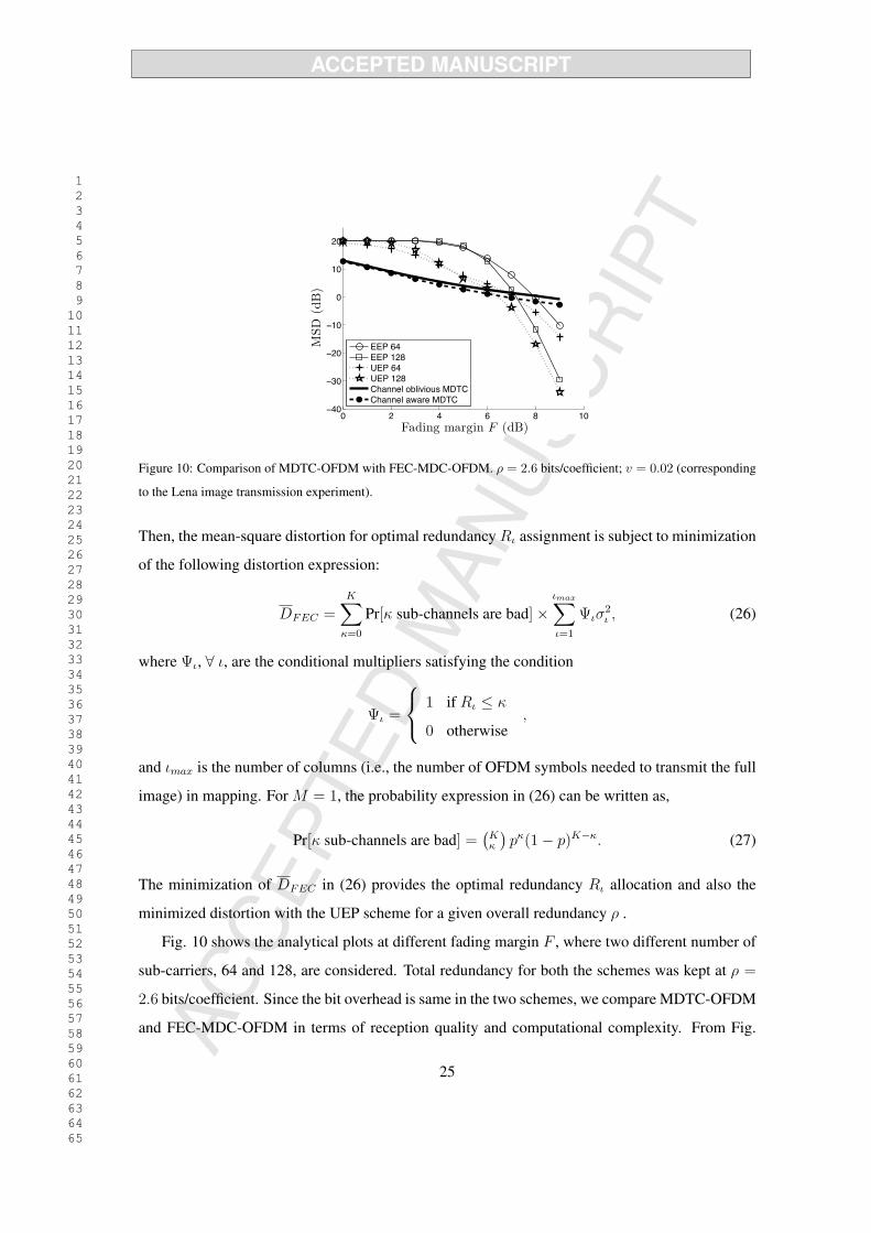
Figure 10: Comparison of MDTC-OFDM with FEC-MDC-OFDM. ρ = 2.6 bits/coefficient; v = 0.02 (corresponding
to the Lena image transmission experiment).
Then, the mean-square distortion for optimal redundancy Rι assignment is subject to minimization
of the following distortion expression:
DFEC =K∑
κ=0
Pr[κ sub-channels are bad] ×ιmax∑
ι=1
Ψισ2ι , (26)
where Ψι, ∀ ι, are the conditional multipliers satisfying the condition
Ψι =
⎧⎨⎩
1 if Rι ≤ κ
0 otherwise,
and ιmax is the number of columns (i.e., the number of OFDM symbols needed to transmit the full
image) in mapping. For M = 1, the probability expression in (26) can be written as,
Pr[κ sub-channels are bad] =(
Kκ
)pκ(1 − p)K−κ. (27)
The minimization of DFEC in (26) provides the optimal redundancy Rι allocation and also the
minimized distortion with the UEP scheme for a given overall redundancy ρ .
Fig. 10 shows the analytical plots at different fading margin F , where two different number of
sub-carriers, 64 and 128, are considered. Total redundancy for both the schemes was kept at ρ =
2.6 bits/coefficient. Since the bit overhead is same in the two schemes, we compare MDTC-OFDM
and FEC-MDC-OFDM in terms of reception quality and computational complexity. From Fig.
25

1 2 3 4 5 6 7 8 9 10 11 12 13 14 15 16 17 18 19 20 21 22 23 24 25 26 27 28 29 30 31 32 33 34 35 36 37 38 39 40 41 42 43 44 45 46 47 48 49 50 51 52 53 54 55 56 57 58 59 60 61 62 63 64 65
10 we can observe that the MDTC-OFDM has a better performance than the FEC-MDC-OFDM
schemes at lower fading margins. Thus, the MDTC provides a higher robustness compared to the
FEC-MDC in bad channel conditions (i.e., at lower values of F ). This is because, as indicated by
(26) and (27), if the number of bad sub-channels κ exceeds the maximum redundancy max{Rι}(which corresponds to the most important stream), then the receiver will not be able to decode any
information, leading to the complete communication outage. The chance of this outage is higher
at a lower F . On the contrary, in MDTC system, redundancy is distributed at the coefficient level
in such a way that even a single stream reception provides some information.
We also observe the dependency of FEC-MDC-OFDM system’s performance on the number
of OFDM sub-carriers. With a lower number of sub-carriers, the performance of FEC-MDC-
OFDM deteriorates, whereas the performance of the MDTC-OFDM is independent of the system
specification in terms of the number of sub-carriers used. The plots also demonstrate that, while
the channel-oblivious MDTC-OFDM system performs poorly with respect to the channel-aware
MDTC-OFDM system at a higher fading margins, it performs rather nearly equally at lower fading
margins, which is also better than that of the FEC-MDC-OFDM system with EEP as well as UEP.
It is important to note that, the complexity involved in obtaining the optimal redundancy as-
signment in FEC-based MDC (with UEP) is very high, which increases with the number of sub-
carriers in the underlying OFDM system. Specifically, the FEC-based MDC requires online com-
putation, with the simplest algorithm for optimal FEC allocation having computational complexity
O (K · L), where K is the number of sub-carriers in the OFDM system and L is the number of
code symbols [20, 32, 23]. This is due to the iterative process of finding an optimum Rι. In con-
trast, the MDTC-OFDM scheme is independent of the number of sub-carriers. In channel-aware
MDTC-OFDM system one needs to perform only the ρ1 assignment, which is a convex optimiza-
tion problem and can be solved by numerical methods. For a given fading margin and a total
redundancy ρ, the channel-aware MDTC-OFDM system requires O(
ρδ
)computations, where δ is
the step size in ρ1 assignment variation, which is much smaller compared to that in the FEC-based
MDC. For example, our optimum ρ1 studies are based on 20 steps of ρ1 assignment. In the channel-
oblivious MDTC-OFDM, the online computational complexity is further reduced to O (1), as the
26

1 2 3 4 5 6 7 8 9 10 11 12 13 14 15 16 17 18 19 20 21 22 23 24 25 26 27 28 29 30 31 32 33 34 35 36 37 38 39 40 41 42 43 44 45 46 47 48 49 50 51 52 53 54 55 56 57 58 59 60 61 62 63 64 65
optimal ρ1 assignment can be obtained by an off-line computation for a given total redundancy ρ.
6. Conclusion
In this paper we have investigated the performance of MDTC transmission of delay-constrained
image/video streaming contents over OFDM broadcast channels, where there are no feedback on
channel gains or having such a feedback is infeasible. At the MDTC construction stage, we have
investigated optimal redundancy assignment in the transform modules and demonstrated the im-
provement in distortion performance at the receiver. At the recovery stage of lost descriptions, we
have demonstrated that, from the knowledge of the distortion introduced by one or more descrip-
tion losses and applying the recovery process at the appropriate transform modules, the distortion
performance can be further improved. We have studied the optimal solution for the channel-aware
MDTC-OFDM system and discussed how closely a sub-optimal channel-oblivious MDTC-OFDM
system can be designed. Finally, we have compared the performance of the proposed MDTC-
OFDM system with that of the FEC-MDC-OFDM system and have demonstrated robustness of
the proposed scheme in severe channel conditions.
Acknowledgment
This work has been supported by the Department of Science and Technology (DST) under the
grant no. SR/S3/EECE/0122/2010. The authors are thankful to the anonymous reviewers for the
insightful comments and valuable suggestions, which have significantly improved the quality of
presentation.
References
[1] V. K. Goyal, Multiple description coding: Compression meets the network, IEEE Sig. Proc.
Mag. 18 (5) (2001) 74–93.
[2] Y. C. Lee, J. Kim, Y. Altunbasak, R. M. Mersereau, Layered coded vs. multiple description
coded video over error-prone networks, Signal Processing: Image Communication 18 (2003)
337–356.
27

1 2 3 4 5 6 7 8 9 10 11 12 13 14 15 16 17 18 19 20 21 22 23 24 25 26 27 28 29 30 31 32 33 34 35 36 37 38 39 40 41 42 43 44 45 46 47 48 49 50 51 52 53 54 55 56 57 58 59 60 61 62 63 64 65
[3] Y. Wang, Q.-F. Zhu, Error control and concealment for video communication: a review,
Proceedings of the IEEE 86 (5) (1998) 974–997.
[4] V. Vaishampayan, Design of multiple description scalar quantizers, IEEE Trans. inform. The-
ory 39 (3) (1993) 821–834.
[5] Y. Frank-Dayan, R. Zamir, Dithered lattice-based quantizers for multiple descriptions, IEEE
Trans. Inform. Theory 48 (1) (2002) 192–204.
[6] J. Ostergaard, R. Zamir, Multiple-description coding by dithered deltasigma quantization,
IEEE Trans. Inform. Theory 55 (10) (2009) 4661–4675.
[7] V. A. Vaishampayan, N. J. A. Sloane, S. D. Servetto, Multiple-description vector quantization
with lattice codebooks: design and analysis, IEEE Trans. Inform. Theory 47 (5) (2001) 1718–
1734.
[8] V. K. Goyal, J. A. Kelner, J. Kovacevic, Multiple description vector quantizationwith a coarse
lattice, IEEE Trans. Inform. Theory 48 (2002) 781–788.
[9] Y. Wang, M. T. Orchard, A. R. Reibman, Multiple description image coding for noisy chan-
nels by pairing transform coefficients, in: Proc. IEEE Workshop on Multimedia Sig. Proc.,
Princeton, NJ, 1997, pp. 419–424.
[10] M. T. Orchard, Y. Wang, V. Vaishampayan, A. R. Reibman, Redundancy rate-distortion anal-
ysis of multiple description coding using pairwise correlating transforms, in: Proc. IEEE Int.
Conf. Image Proc., Santa Barbara, CA, 1997.
[11] V. K. Goyal, J. Kovacevic, Generalized multiple description coding with correlating trans-
forms, IEEE Trans. Image Proc. 47 (2) (2001) 2199–2224.
[12] A. Albanese, J. Blomer, J. Edmonds, M. Luby, M. Sudan, Priority encoding transmission,
IEEE Trans. inform. Theory 46 (6) (1996) 1737–1744.
28

1 2 3 4 5 6 7 8 9 10 11 12 13 14 15 16 17 18 19 20 21 22 23 24 25 26 27 28 29 30 31 32 33 34 35 36 37 38 39 40 41 42 43 44 45 46 47 48 49 50 51 52 53 54 55 56 57 58 59 60 61 62 63 64 65
[13] R. Puri, K. W. Lee, K. Ramchandran, V. Bharghavan, An integrated source transcoding and
congestion control paradigm for video streaming in the Internet, IEEE Trans. Multimedia
3 (1) (2001) 18–32.
[14] R. Razavi, M. Fleury, M. Ghanbari, Adaptive packet-level interleaved FEC for wireless
priority-encoded video streaming, Hindawi J. Advances in Multimedia 2009.
[15] S. S. Arslan, P. C. Cosman, L. B. Milstein, Coded hierarchical modulation for wireless pro-
gressive image transmission, IEEE Trans. Vehicular Technol. 60 (9) (2011) 4299–4313.
[16] E. Baccaglini, T. Tillo, G. Olmo, Image and video transmission: a comparison study of us-
ing unequal loss protection and multiple description coding, Springer Multimedia Tools and
Applications: Spl. Issue Mobile Media Delivery 55 (2) (2011) 247–259.
[17] K. Khelil, R. E. H. Bekka, A. Djebari, J. M. Rouvaen, Multiple description wavelet-based
image coding using correlating transforms, Int. J. Electron. Commun. 61 (2007) 411–417.
[18] J. N. Laneman, E. Martinian, G. W. Wornell, J. G. Apostolopoulos, S. J. Wee, Comparing
application and physical layer approches to diversity on wireless channels, in: Proc. IEEE
ICC, Anchorage, AK, USA, 2003.
[19] H. Zheng, C. Ru, L. Yu, C. W. Chen, Robust video transmission over MIMO-OFDM system
using MDC and space time codes, in: Proc. IEEE Intl. Conf. Multimedia and Expo, Toronto,
Ontario, Canada, 2006, pp. 633–636.
[20] A. E. Mohr, E. A. Riskin, R. E. Ladner, Graceful degradation over packet erasure channels
through forward error correction, in: Proc. IEEE Data Compression Conf., 1999, pp. 92–101.
[21] S. S. Pradhan, R. Puri, K. Ramchandran, n-channel symmetric multiple descriptions - Part I:
(n, k) source-channel erasure codes, IEEE Trans. inform. Theory 50 (1) (2004) 47–61.
[22] S. Zhao, D. Tuninetti, R. Ansari, D. Schonfeld, Multiple description coding over correlated
multipath erasure channels, in: Proc. ICASSP, Las Vegas, NV, USA, 2008.
29

1 2 3 4 5 6 7 8 9 10 11 12 13 14 15 16 17 18 19 20 21 22 23 24 25 26 27 28 29 30 31 32 33 34 35 36 37 38 39 40 41 42 43 44 45 46 47 48 49 50 51 52 53 54 55 56 57 58 59 60 61 62 63 64 65
[23] Y. S. Chan, P. C. Cosman, L. B. Milstein, A cross-layer diversity technique for multi-carrier
OFDM multimedia networks, IEEE Trans. Image Proc. 15 (4) (2006) 833–847.
[24] S.-H. Chang, P. C. Cosman, L. B. Milstein, Performance analysis of n-channel symmetric
FEC-based multiple description coding for OFDM networks, IEEE Trans. Image Proc. 20 (4)
(2011) 1061–1076.
[25] L. Toni, Y. S. Chan, P. C. Cosman, L. B. Milstein, Channel coding for progressive images in
a 2-D time-frequency OFDM block with channel estimation errors, IEEE Trans. Image Proc.
18 (11) (2009) 2476–90.
[26] Y. S. Chan, P. C. Cosman, L. B. Milstein, A multiple description coding and delivery scheme
for motion-compensated fine granularity scalable video, IEEE Trans. Image Proc. 17 (8)
(2008) 1353–1367.
[27] C. Christopoulos, A. Skodras, T. Ebrahimi, The JPEG2000 still image coding system: An
overview, IEEE Trans. Consumer Electron. 46 (4) (2000) 1103–1127.
[28] E. Setton, Y. Liang, B. Girod, Adaptive multiple description video streaming over multiple
channels with active probing, in: Proc. Intl. Conf. Multimedia and Expo, Baltimore, MD,
USA, 2003.
[29] V. K. Goyal, J. Kovacevic, Optimal multiple description transform coding of Gaussian vec-
tors, in: Proc. IEEE Data Compression Conf., Vol. I, Snowbird, UT, 1998, pp. 388–397.
[30] M. Medard, R. G. Gallager, Bandwidth scaling for fading multipath channels, IEEE Trans.
inform. Theory 48 (4) (2002) 840–852.
[31] S. Coleri, M. Ergen, A. Puri, A. Bahai, Channel estimation techniques based on pilot arrange-
ment in OFDM system, IEEE Trans. Broadcasting 48 (3) (2002) 223–229.
[32] V. M. Stankovic, R. Hamzaoui, Z. Xiong, Real-time error protection of embedded codes for
packet erasure and fading channels, IEEE Trans. Circuits, Syst., Video Technol. 14 (3) (2004)
1064–1072.
30
*Brief BiographyClick here to download Brief Biography: authors_bio.txt


*Au
tho
r P
ho
toC
lick
her
e to
do
wn
load
hig
h r
eso
luti
on
imag
e

*Au
tho
r P
ho
toC
lick
her
e to
do
wn
load
hig
h r
eso
luti
on
imag
e

*Author PhotoClick here to download high resolution image

*Author PhotoClick here to download high resolution image