Multiple Access Technique Lecture 8 - Website Staff...
44
Multiple Access Technique Lecture 8 Ir. Muhamad Asvial, MEng., PhD Center for Information and Communication Engineering Research Electrical Engineering Department – University of Indonesia Kampus UI Depok, 16424 – Indonesia [email protected] http://www.ee.ui.ac.id
Transcript of Multiple Access Technique Lecture 8 - Website Staff...

Multiple Access Technique
Lecture 8
Ir. Muhamad Asvial, MEng., PhDCenter for Information and Communication Engineering Research
Electrical Engineering Department – University of Indonesia Kampus UI Depok, 16424 – Indonesia
[email protected]://www.ee.ui.ac.id

Multipexing TechniquesMultipexing Techniques1. Duplexing 2. Multiplexing Techniques Frequency Division Multiplexing (FDM) Time Division Multiplexing (TDM) Code Division Multiplexing (CDM) Wavelength Division Multiplexing (WDM)
3. Multiple Access Techniques Frequency Division Multiple Access (FDMA) Time Division Multiple Access (TDMA) Code Division Multiple Access (CDMA) Direct Sequence CDMA
Spatial Division Multiple Access (SDMA)

Since the RF spectrum is a finite and limited resource, it is necessary to share the available resources between users
Format
ChannelEncoder
SourceEncoder
Format ChannelDecoder
SourceDecoder
Bits orSymbol
To otherdestinations
From othersources
Digitalinput
Digitaloutput
Sourcebits
Sourcebits
Channelbits
Carrier & symbolsynchronization
Channelbits
mil q
mil q
Tx
Rx
PerformanceMeasure
Pe
Modulate
Demodulate&
Detect
Spread MultipleAccess
Waveforms
MultipleAccessDespreadDemultiplex
Multiplex

DuplexingDuplexingA technique commonly used in many radio and telecommunication between a pair of users –
Tx and Rx
Simplex– Information is transmitted in one and only one pre-assigned direction\
Half Duplex– Transmission of information in only one direction at a time– Uses simplex operation at both end
Full Duplex– Simultaneous transmission and reception of info in both directions– In general, duplex operation require 2 frequencies– May be achieved by simplex operation of 2 or more simplex at both ends
• Duplexing can be implemented in either Frequency or Time domain– Frequency Division Duplexing (FDD) & Time Division Duplexing (TDD)
Terminal A Terminal B
Terminal A Terminal B
Terminal A Terminal B
Full-duplex
Half-duplex
Simplex

• Frequency Division Duplexing (FDD)– Multiplexes the Tx and Rx in one time slot in which transmission
and reception is on 2 different frequencies– It provides simultaneous transmission channels for mobile/base
station• i.e. each channel has a Forward and a Reverse frequency
– At the base station, separate transmit and receive antennas are used to accommodate the two separate channels
– At the mobile unit, a single antenna (with duplexer) is used to enable transmission and reception
– To facilitate FDD, sufficient frequency isolation of the transmit and receive frequencies is necessary
– FDD is used exclusively in analog mobile radio systems
Frequency Division Duplexing (TDD)

Time Division Duplexing Time Division Duplexing (TDD)(TDD)
– Multiplexes the Tx & Rx in one frequency at different time slots
– A portion of the time is used to transmit and a portion is used to receive
– TDD is used, for example, in a simple 2-way radio where a button is pressed to talk and released to listen
– If the data rate from the base station >> the end-user’s data rate, it is possible to use buffer-and-burst transmission (giving the appearance of full duplex)
– TDD is only possible for digital transmission
Time Division Duplexing
Time
Am
plitu
deT TR R

Multiplexing TechniquesMultiplexing Techniques• Multiplexing (sometimes called channelization) is the
process of simultaneously transmitting several information signals using a single communication channel
• Commonly used to separate different users such that they share the same resource without interference
• Three major kinds– Frequency Division Multiplexing– Time Division Multiplexing– Code Division Multiplexing
• Communication recourses are allocated a priori and allocated resources are fixed
• Only one pair of transceivers are required

Frequency Division MultiplexingFrequency Division Multiplexing• In FDM, the available bandwidth is divided into non-overlapping
frequency slots• Each message is assigned a frequency slot within the available band• Signals are translated to different frequency band using modulation
and then added together to form a baseband signal• The signals are narrowband and frequency limited
• FDM can be used for either digital or analog transmission
Frequency Band 1
Frequency Band 2
Frequency Band N
f0
f2
fN-2
fN-1
f1
f3
Time
Freq
uenc
y

Time Division Multiplexing (TDM)Time Division Multiplexing (TDM)• Digitized info from several sources are multiplexed in time and
transmitted over a single communication channel• The communication channel is divided into frames of length Tf• Each frame is further segmented into N subinterval called slots, each
with duration Ts = Tf/N, where N is the number of users
• Each user is assigned a slot (or channel) within each time frame• TDM is used to combine several low bit rate signals to form a high-
rate signal to be transmitted over a high bit rate medium• Individual message signals need not have the same rate, or same type
of signal since each channel is independent of one another• TDM is usually used for digital commun. and cannot be used in
analog commun.
Slot1
Slot2
SlotNs1 s2 sk . . .
FRAME
. . .
Sync word Information or data word
s1 s2 . . .SlotN. . .

Code Division MultiplexingCode Division Multiplexing• CDM is a multiplexing method where multiple users are
permitted to transmit simultaneously on the same time and same frequency
• In CDM system, users time share a higher-rate digital channel by overlaying a higher-rate digital sequence on their transmission
• Each user is assigned distinct code sequence (or waveform)• This technique may be viewed as a combination of FDM and
TDM using some sort of code
Signal 1
Signal 3
Signal 2
......
Freq
uenc
y D
omai
n
Time Domain
Signal 2
Signal 1
Signal 3...
Signal 1
Signal 3
Signal 2
...
...
...
Slot 1 Slot 2 Slot 3
Band 1
Band 2
Band 3
Code Division Multiplexing

Wavelength Division Multiplexing Wavelength Division Multiplexing (WDM)(WDM)
In optics, the process of using laser source, repeater amplifier, and optical detector to independently modulated light carriers to be sent over a single fiber is known as WDM
This process has been very difficult until recently
fc of light with sufficient spectral stability is required and was not available until recently
Each individual light carrier could support data rates of up to 10 Gbps with users time multiplexed onto the channelWDM thus offers the possibility of several hundreds of gigabits transmission over a single fiber and also bi-direction transmission over the same fiber

Multiple Access TechniquesMultiple Access TechniquesDefinition:• Multiple Access (MA) techniques are multiplexing
protocols that allow more than a pair of transceivers to share a common medium
• Allocation of resources– not defined a priori– not necessarily fixed
• Multiple Access can be implemented in– Frequency - FDMA– Time - TDMA– Code - CDMA– Combinations (Frequency, Time and Code)

Types of Multiple Access Techniques:• Frequency Division Multiple Access (FDMA)
– Uses different frequencies for different users• Time Division Multiple Access (TDMA)
– Uses same frequency but different time for different users• Code Division Multiple Access (CDMA)
– Uses same frequencies and time but different codes (3G wireless systems)• Space/spatial Division Multiple Access (SDMA)
– Uses spot beam antennas to separate radio signals by pointing at different users with different spot beam, e.g., ACTS
• Demand Access Multiple Access (DAMA)– Uses dynamic assignment protocol (allocates resources on request)
• Random Access Multiple Access (RAMA)• Hybrid Multiple Accesses
– Time Division CDMA, Time Division Frequency Hopping, FDMA/CDMA, etc.

Frequency Division Multiple AccessFrequency Division Multiple Access
1 2 n
B
FRAME
Guard band (at the edges & between) tominimize crosstalk
Frequency 1
...
Frequency 2
Frequency n
Frequency 1
...
Frequency 2
Frequency n
Circuit Circuit
Circuit
Circuit Circuit
Circuit
Time Domain
FrequencyDomain
DownlinkPath
UplinkPath

• Individual frequencies are assigned to individual users on demand • FDMA allocates a single channel to one user at a time• Users use the channel for entire duration of call• If the transmission path deteriorates, the controller switches the
system to another channel• Although technically simple to implement, FDMA is wasteful of
BW– Channel is assigned to a single conversation whether or not
somebody is speaking– It cannot handle alternate forms of data, only voice is
permissible• Used extensively in the early telephone and wireless multi-user
communication systems• FDMA is the most commonly used access protocol especially for
satellite communication

FDMAFDMA• In a cluster, each user is assigned a portion of the available bandwidth
• Let – Ndata = number of data channel– Nctl = number of control channel
• Total Bandwidth
• Number of Channels ,s data ctlN N Nor N
2s s c gB N B B
2s gs
c
B BN N
B
2s data c ctl c gB N B N B B
data c sN B B
Channel1
Channel2 ...... Channel
Ns
Bs
BcBg MHz

• Number of channels per cluster
• Number of channels per cell
• Number of data channels per cluster
• Number of data channels per cell
/
2s gch cluster
c
B BN
B
//
ch clusterch cell
NNN
/ / /data cluster ch cluster ctl clusterN N N
//
data clusterdata cell
NNN

• Number of calls per hour per cell
where t id the trunk efficiency• Average number of users per hour per cell
• Spectral Efficiency
number of calls/hour/cellaverage # of calls/user/houruserN
2# of data channel/cluster chls/MHz/km
sytem BWdata / cluster
cluster s cell
NA B N A
/ number of calls per hourch clustercalls t
NNN
BW available for data transmission 1
sytem bandwidthdata c
FDMAs
N BB

• FDMA Capacity
• Note that some textbooks will not account for guard bands in-between users. However, we can also have
s
s c g
BCN B B
Channel1
Channel2 ...... Channel
Ns
Bs
Bc
Bg
MHz
Guard Bands
(#)
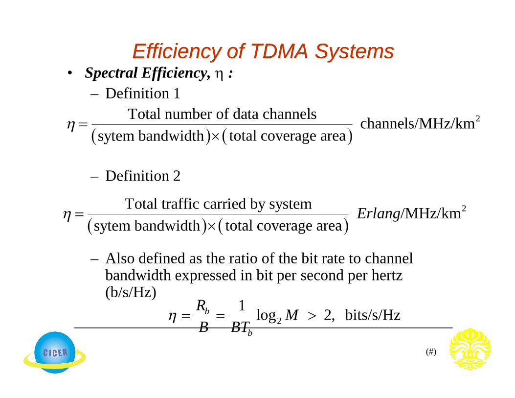
• Spectral Efficiency, :– Definition 1
– Definition 2
– Also defined as the ratio of the bit rate to channel bandwidth expressed in bit per second per hertz (b/s/Hz)
Efficiency of TDMA SystemsEfficiency of TDMA Systems
2Total number of data channels channels/MHz/km
total coverage areasytem bandwidth
2Total traffic carried by system /MHz/km
total coverage areasytem bandwidthErlang
21 log 2, bits/s/Hzb
b
R MB BT
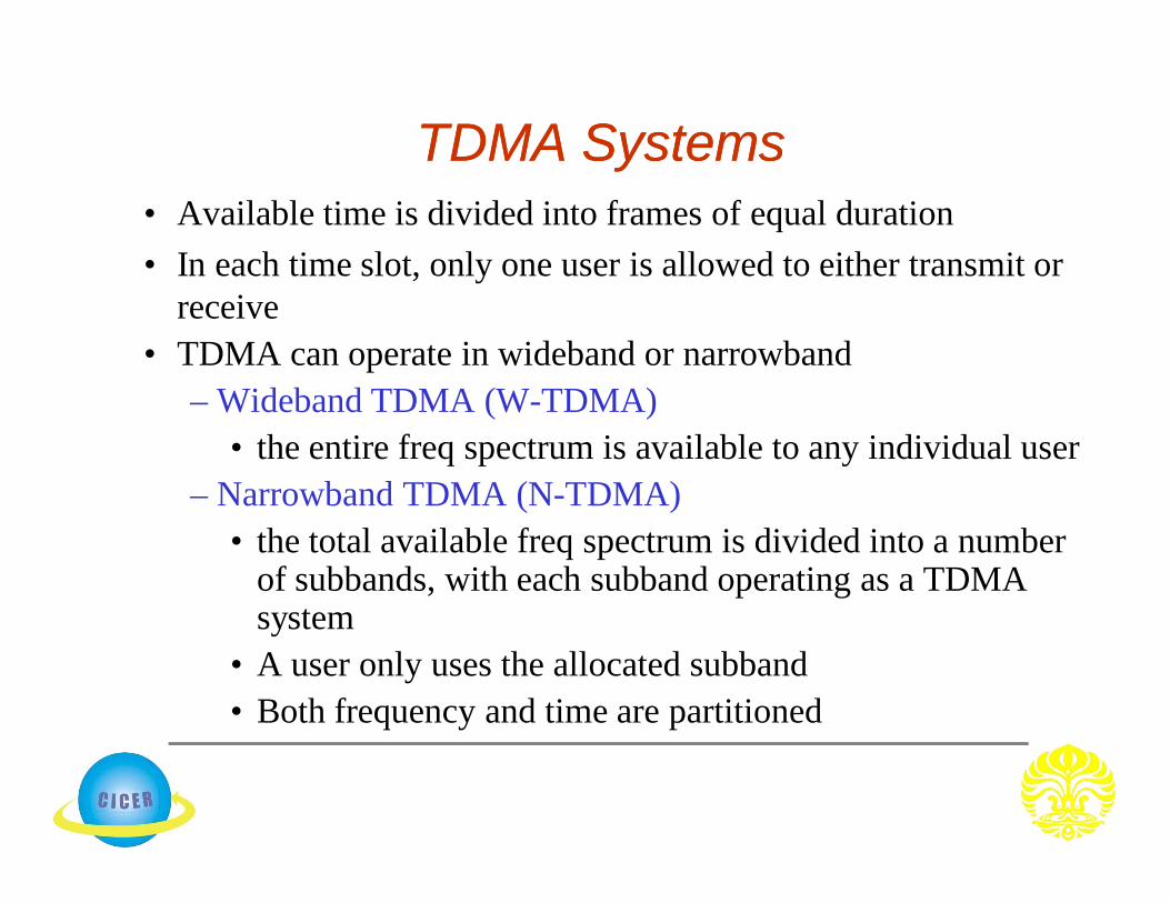
TDMA SystemsTDMA Systems• Available time is divided into frames of equal duration• In each time slot, only one user is allowed to either transmit or
receive• TDMA can operate in wideband or narrowband
– Wideband TDMA (W-TDMA)• the entire freq spectrum is available to any individual user
– Narrowband TDMA (N-TDMA)• the total available freq spectrum is divided into a number
of subbands, with each subband operating as a TDMA system
• A user only uses the allocated subband• Both frequency and time are partitioned

Time Division Multiple AccessTime Division Multiple AccessFrequency 1
...
Frequency 2
Frequency n
Frequency 1
...
Frequency 2
Frequency n
Time Domain
Freq
uenc
y D
omai
n
circuit circuit circuit
circuit circuit circuit
circuit circuit circuit
circuit circuit circuit
circuit circuit circuit
circuit circuit circuit
DownlinkPath
UplinkPath
slot 1 slot 2 slot 2
Control Bits
Slot 1
Trail BitsInformation Data
Slot 2 Slot 3 Slot N
Guard BitsInformation DataTrail Bits Sync. Bits
One TDMA FrameTDMA/FDD

• The number of time slots per frame is a design parameter depending on requirements such as modulation, bandwidth, data rate, etc.
• TDMA transmits data in a “buffer-and-burst” technique and hence transmission is not continuous– low battery consumption is achieved, and simplification
of handoff process is achievable• Transmission from users are interlaced into cyclic time
structure• Since different transceivers are used for communication,
duplexer may not be required• TDMA requires very high data rate compared to FDMA
and hence equalization is not required

Time Division Multiple AccessTime Division Multiple Access• Available time is divided into frames of equal duration
• In each time slot, only one user is allowed to either transmit or receive• Guard time separates the users
Control Bits
Slot 1
Trail BitsInformation Data
Slot 2 Slot 3 Slot N
Guard BitsInformation DataTrail Bits Sync. Bits
One TDMA Frame

(#)
TDMA OperationTDMA Operation

• No inter-modulation impairment– Since TDMA uses one carrier at a time
• No interference from other simultaneous transmissions– TDMA’s technology separates users in time ensuring that they will
not experience interference from other simultaneous transmissions• Flexibility
– TDMA can be easily adapted for the transmission of data or voice• Variable rates
– TDMA offers the ability to carry data rates of 64 kbps to 120 Mbps (expandable in multiples of 64 kbps)
– This enables operators to offer personal communication services including fax, voice-band data, and short message services as well as bandwidth-intensive applications such as multimedia and videoconferencing
Advantages

(#)
• Bandwidth efficient protocol– TDMA uses bandwidth more effectively because no frequency
guard bands are required between channels• Low power consumption
– since transmission is bursty and non-continuous– i.e, TDMA provides the user with extended battery life and talk
time since the mobile is only transmitting a portion of the time (from 1/3 to 1/10) during conversations
• Guard time between time slots may be used to accommodate– clock instability– delay spread– transmission (or propagation) delays and pulse spreading
• Achieves selectivity in time domain, and selectivity is simpler than FDMA
• TDMA devices can be mass produced by VLSI giving rise to low cost
(#)
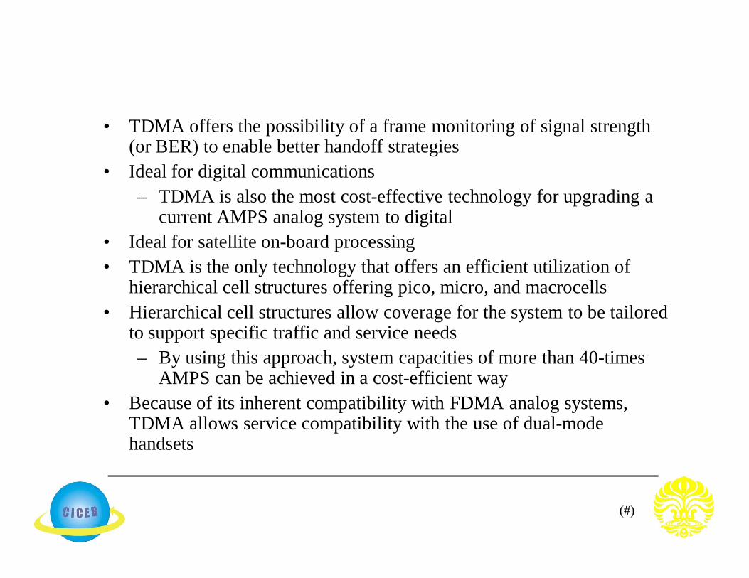
• TDMA offers the possibility of a frame monitoring of signal strength (or BER) to enable better handoff strategies
• Ideal for digital communications– TDMA is also the most cost-effective technology for upgrading a
current AMPS analog system to digital• Ideal for satellite on-board processing• TDMA is the only technology that offers an efficient utilization of
hierarchical cell structures offering pico, micro, and macrocells• Hierarchical cell structures allow coverage for the system to be tailored
to support specific traffic and service needs– By using this approach, system capacities of more than 40-times
AMPS can be achieved in a cost-efficient way• Because of its inherent compatibility with FDMA analog systems,
TDMA allows service compatibility with the use of dual-mode handsets

(#)
• In TDMA, each user has a predefined time slot. However, users roaming from one cell to another are not allotted a time slot– Thus, if all the time slots in the next cell are already
occupied, a call might well be disconnected • Likewise, if all the time slots in the cell in which a user
happens to be in are already occupied, a user will not receive a dial tone
• TDMA is subjected to multipath distortion because of its sensitivity to timing– Even at thousandths of seconds, these multipath signals
cause problems• Overall TDMA is more complex and costly compared to
FDMA
Disadvantages

(#)
• Wideband TDMA (W-TDMA)– the entire frequency spectrum is available to
any individual user• Narrowband TDMA (N-TDMA)
– the total available frequency spectrum is divided into a number of subbands, with each subband operating as a TDMA system
– A user only uses the allocated subband– both frequency and time are partitioned
TDMA SystemsTDMA Systems

TDMA SystemsTDMA Systems• Basic Frame Structure
• Let– Bs = Bt = total spectrum allocation– Bg = guard band– Bc = Channel bandwidth – Bandwidth of individual user– N = frequency reuse factor– Nu = number of subbands– Ld = the number of information data symbols in each slot– Ls, = the total number of symbols in each slot
1 2 ...... (N-1)slot TrailerPreamble
Tf
T1 sec
Nslot3
T2TNslotp t

• Number of users
where
• Cell Capacity, Ncell
– where sf is the source activity factor defined as the % of time the connected mobile is actually getting information
s u slotN N N
1, for W-TDMA2
, for N-TDMAs gu
c
B BNB
u slotcell
N NNN
u slotcell
f
N NNs N
For voice communication with talk spurt (on) state and silence (off) state
Nslot = m in your textbook
Capacity of TDMA System

Code Division Multiple AccessCode Division Multiple Access
• CDMA technology focuses primarily on the “DSSS” technique • Instead of using freq or time slots, it uses digital codes to distinguish
between multiple users• Each user is assigned a unique PN code sequence• The assigned code is uncorrelated with the data • Because the signals are distinguished by digital codes, many users can
share the same bandwidth simultaneously– i.e., signals are transmitted in the same frequency at the same time
• Multiplying the data by the high data rate PN code results in dividing the signal into smaller bits, thus, increasing its BW
• The PN code used for spreading must have – low cross-correlation values and – be unique to every user
(#)
Advantages:1. Voice Activities Cycles
– CDMA is the only one technique that succeeds in taking advantage of the nature of human conversation
– In CDMA, all the users are sharing one radio channel– The human voice activity cycle is 35%, the rest of the time we
are listening– Because each channel user is active just 35% of the entire cycle,
all others benefit with less interference in a single CDMA radio channel
– So, the mutual interference is in a nice-free way, reduced by 65%; and thus, the channel capacity is increased about 3 times
2. Improved call quality, with better and more consistent sound as compared to other systems
Advantages & DisadvantagesAdvantages & Disadvantages

(#)
3. No Equalizer Needed– When the transmission rate is much higher than 10 kbps in both
FDMA and TDMA, an equalizer is required– On the other hand, CDMA only needs a correlator, which is
cheaper than the equalizer4. No Hard Handoff
– In CDMA, every cell uses the same radio– This feature avoids the process of handoff from one freq to
another while moving from one cell to another5. No Guard Time in CDMA
– TDMA requires the use of guard time between time slots• guard time does occupy the time interval for some info bits
– This “waste” of bits does not exists in CDMA, because guard time is not needed in CDMA technique
(#)
6. Less Fading– Less fading is observed in the wide-band signal while
propagating in a mobile ratio environment7. Capacity Advantage
– Given correct parameters, CDMA can have as much as four times the TDMA capacity; and twenty times FDMA capacity per channel/cell
8. No frequency management or assignment needed– In both, TDMA and FDMA, the frequency management is
always a critical– Since there is only one channel in CDMA, no frequency
management is needed9. Enhanced privacy
– CDMA signals resistant to interception or jamming

(#)
10. Soft Capacity– Because in CDMA all the traffic channels share a
single radio channel, we can add one additional user so the voice quality is just slightly degraded
11. Coexistence– Both systems, analog and CDMA can operate in two
different spectra, with no interference at all12. Simplified system planning through the use of the
same frequency in every sector of every cell– Improved coverage characteristics, allowing for the
possibility of fewer cell sites13. Increased talk time for portables14. Bandwidth on demand

(#)
Disadvantages:1. Capacity not well defined
– The capacity of CDMA systems is not well defined. The effective (Eb/No) formula demonstrates the interference-limited nature of the system, but more than one factor in that formula is affected by the number of users, making it hard to gauge how performance degrades as a function of users
2. The Near-Far Problem– The main problem with applying DS/CDMA is the
so-called “Near-Far” effect– This effect is present when an interfering Tx is much
closer to the Rx than the intended Tx – Assume there are 2 users, one near the base and one
far from the base as shown
(#)
• Universal Frequency Reuse– Uses one universal cell frequency reuse pattern applies
• This turns out to be beneficial and improves the capacity of the system
• Ease of freq management is also found in DS/CDMA• Power Control
– Reverse Link (from mobile unit to base station)• link is designed to be asynchronous and is susceptible to the
“near-far” problem• In order to remedy this, the use of power control is employed
– To ensure all signals from the mobiles with a given cell arrive at the base of the cell with equal power
– To maximize the total user capacity – To minimize power consumption of portable units
Characteristic of DS/CDMACharacteristic of DS/CDMA
(#)
• Effective use of the power control will ensure that power control must be accurate and fast enough to compensate for fading
– Forward Link (from base station to mobile unit) • Link does not suffer much from near-far problem
since all cell signals can be received at the mobile with equal power
• When at excessive intercell interference, the power control can be applied by increasing the power to the mobile

Hybrid Multiple Access TechniquesHybrid Multiple Access Techniques
• Some practical systems combine two or more of these multiplexing or multiple access techniques
• Hybrid systems are used to overcome the shortcomings of a single SS or access technique in a given application
• Frequency Division Multiple Access CDMA (FCDMA)– Available spectrum is divided into subbands – Each subbands is then considered as a narrow band CDMA system– GSM, although primarily a TDMA system, requires several
200 kHz freq channels (each carrying eight time slots) in order to provide a practical high capacity cellular system and can also be viewed as an FDMA system also
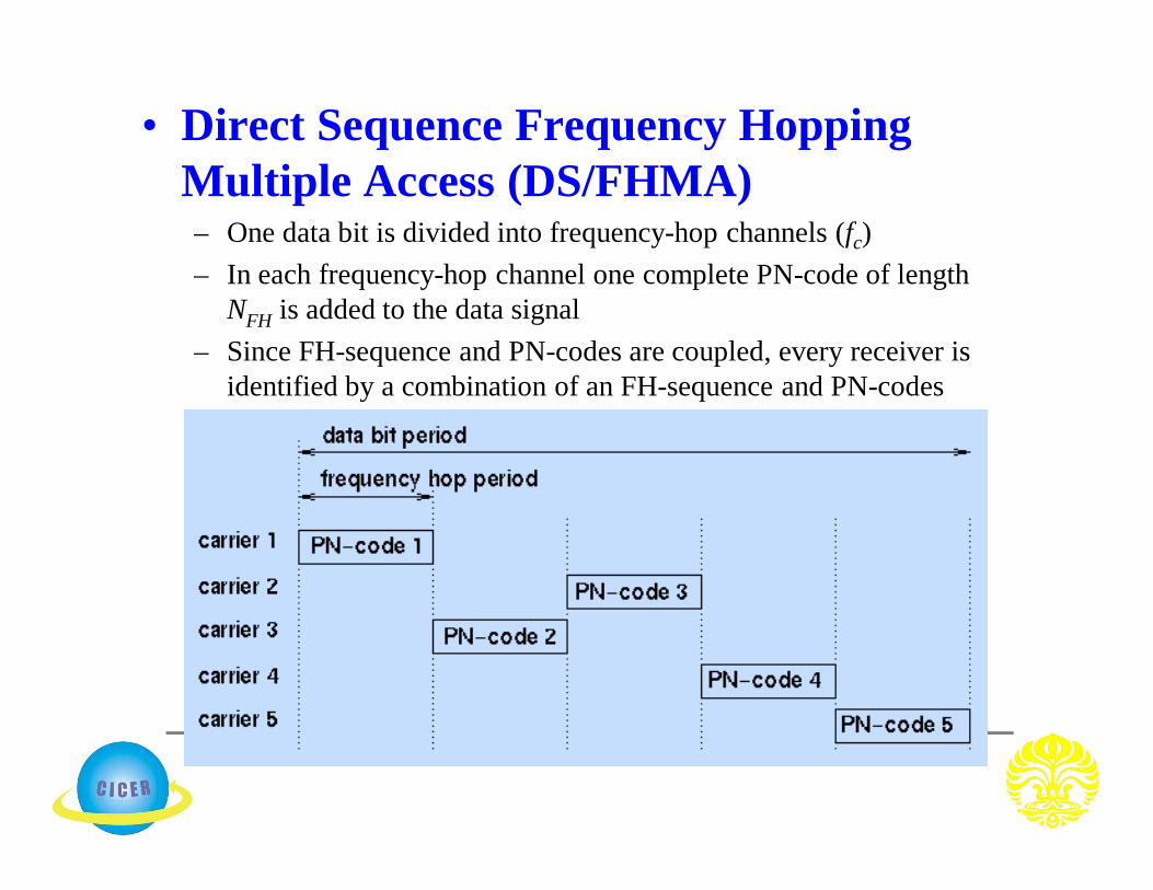
• Direct Sequence Frequency Hopping Multiple Access (DS/FHMA)– One data bit is divided into frequency-hop channels (fc)– In each frequency-hop channel one complete PN-code of length
NFH is added to the data signal– Since FH-sequence and PN-codes are coupled, every receiver is
identified by a combination of an FH-sequence and PN-codes

• Time Division CDMA (TCDMA)– Different spreading codes are assigned to different cells– Within each cell, only one user is allocated a particular time slot
such that only one user is transmitting in each cell at one slot
• Time Division Frequency Hopping (TDFH)– At the start of a new TDMA frame, the user hops to a new channel– This avoids severe fades or erasure in any particular channel– The user is allowed to hop according to a predefined sequence– TXs are made to transmit on different freqs at different times
• Space Division Multiple Access (SDMA) – Also called multiple beam frequency reuse– Different areas of the cell is covered by
multiple beam antenna system– Makes use of orthogonality in geometry (spatial
channel separation)– Each of the coverage area may use either
FDMA, TDMA or CDMA– An example of SDMA is sectored antennas – Adaptive antennas (or smart antennas) is most
likely to be used for the future for the realization of SDMA