
MULTIPATH TRANSMISSION EFFECTS IN FM … Bound...MULTIPATH TRANSMISSION EFFECTS IN FM RECEPTION AND...
10
1960/61, No. 12 393 MULTIPATH TRANSMISSION EFFECTS IN FM RECEPTION AND THEIR SIMULATION IN THE LABORATORY by J. KOSTER *). In mountainous regions the waves from a broadcasting transmitter may reach the receiver along multiple paths of different length as a result of reflections from mountain ridges. The consequence of this in frequency-modulated broadcasts may be severe distortion of the sound. The author has designed a signal generator for simulating and studying this interference in the laboratory. This makes it possible to check at any time, irrespective of receiving conditions, the effect of measures laken in the receiver to reduce this distortion. In FM broadcasting (frequency-modulated VHF transmissions) use is made of waves in the metre bands. These waves as a rule reach the re- ceivers along the direct path from transmitting to receiving aerial. Not infrequently, however, one or more other transmission paths may exist at the same time, owing to the waves being reflected from some natural obstacle, such as a mountain ridge. The various paths will generally differ in length, which means that two or more waves having dif- ferent transit times and hence a phase difference arrive at the receiving aerial. The consequence, particularly if the reflected waves are not much weaker than the direct wave, is a peculiar distortion of the detected signal. The impression one receives is as if the output amplifier.were overloaded, or as if something were loose in the loudspeaker. The cause, however, is of quite a different nature, as will appear from the analysis given below. The distortion in question was very soon noticed when frequency modulation first began to be used. Its cause was also correctly ascertained, and meas- ures for improvement were proposed 1) 2) 3) 4). In this connection the investigations led by Arguimbau made an especially useful contribution 3). In order to study the effect of these measures, a signal generator is needed which is capable of delivering a *) Radio, Television and Record-player Division, Eindhoven. 1) M. S. Corrington, Frequency-modulation distortion caused by multipath transmission, Proc. Inst. Radio Engrs. 33, 878-889, 194·5. M. S. Corrington, Frequency modulation distortion caused by common- and adjacent-channel interference, R.C.A. Rev. 7, 522-560, 1946. 2) F. L. H. M. Stumpers, Interference problems in frequency modulation, Philips Res. Repts. 2, 136-160, 1947. 3) L. B. Arguimbau and J. Granlund, The possibility of trans- atlantic communication by means of frequency modulation, Proc. Nat. Electronics Conf., Part lIl, 644-653, 1947. L. B. Arguimbau and J. Granlund, Interference in FM reception, Tech. report No. 42, Research Lab. ofElectronics, Massachusetts Inst. of Technology, 1947. 4) L. W. Johnson, F.M. receiver design, Wireless World 62, 497-503, 1956. 621.391.826.2:621.376.33 signal corresponding to that which an aerial re- ceives under the conditions mentioned. A relatively simple solution of this problem is described in the present article. To make clear the requirements to be met by such a signal generator, we shall first give a simplified analysis of the effects' involved. The FM receiver Fig. 1 shows the familiar block diagram of a normal FM broadcast receiver. The audio-frequency section (A3-L) need not be considered here. The Ant Fig. 1. Block diagram of a conventional FM broadcast receiver. Ant aerial. Al radio-frequency amplifier. M mixer. 0 local oscillator. A 2 intermediate-frequency amplifier. Lim limiter. D FM detector (discriminator). A3 audio-frequency amplifier. L loudspeaker. (For clarity the limiter is shown as a separate bloek; in reality, limiting occurs partly in the last stage of A2' partly in the discriminator.) radio-frequency amplifier (AI)' the mixer (M) and the intermediate-frequency amplifier (A 2 ) can be re- garded for our purposes as linear networks, in other words, we may apply to them the superposition theorem. This states that in the simultaneous pres- ence of more than one signal the total effect is the sum of the effects of the individual signals, provided only that the amplitude characteristic is sufficiently horizontal and the phase characteristic sufficiently straight. These conditions are reasonably satisfied if the bandwidth of the amplifiers is not less than about three times the maximum frequency devia- tion of the transmitted signal. In the case of FM broadcasting stations the maximum frequency deviation is fixed at 75 kcfs by international agree- ment.
Transcript of MULTIPATH TRANSMISSION EFFECTS IN FM … Bound...MULTIPATH TRANSMISSION EFFECTS IN FM RECEPTION AND...
1960/61, No. 12 393
MULTIPATH TRANSMISSION EFFECTS IN FM RECEPTIONAND THEIR SIMULATION IN THE LABORATORY
by J. KOSTER *).
In mountainous regions the waves from a broadcasting transmitter may reach the receiveralong multiple paths of different length as a result of reflections from mountain ridges. Theconsequence of this in frequency-modulated broadcasts may be severe distortion of the sound.The author has designed a signal generator for simulating and studying this interference in thelaboratory. This makes it possible to check at any time, irrespective of receiving conditions, theeffect of measures laken in the receiver to reduce this distortion.
In FM broadcasting (frequency-modulatedVHF transmissions) use is made of waves in themetre bands. These waves as a rule reach the re-ceivers along the direct path from transmittingto receiving aerial. Not infrequently, however, oneor more other transmission paths may exist at thesame time, owing to the waves being reflected fromsome natural obstacle, such as a mountain ridge.The various paths will generally differ in length,which means that two or more waves having dif-ferent transit times and hence a phase differencearrive at the receiving aerial. The consequence,particularly if the reflected waves are not muchweaker than the direct wave, is a peculiar distortionof the detected signal. The impression one receivesis as if the output amplifier. were overloaded, or asif something were loose in the loudspeaker. Thecause, however, is of quite a different nature, aswill appear from the analysis given below.
The distortion in question was very soon noticedwhen frequency modulation first began to be used.Its cause was also correctly ascertained, and meas-ures for improvement were proposed 1) 2) 3) 4). Inthis connection the investigations led by Arguimbaumade an especially useful contribution 3). In orderto study the effect of these measures, a signalgenerator is needed which is capable of delivering a
*) Radio, Television and Record-player Division, Eindhoven.1) M. S. Corrington, Frequency-modulation distortion caused
by multipath transmission, Proc. Inst. Radio Engrs. 33,878-889, 194·5.M. S. Corrington, Frequency modulation distortion causedby common- and adjacent-channel interference, R.C.A.Rev. 7, 522-560, 1946.
2) F. L. H. M. Stumpers, Interference problems in frequencymodulation, Philips Res. Repts. 2, 136-160, 1947.
3) L. B. Arguimbau and J. Granlund, The possibility of trans-atlantic communication by means of frequency modulation,Proc. Nat. Electronics Conf., Part lIl, 644-653, 1947.L. B. Arguimbau and J. Granlund, Interference in FMreception, Tech. report No.42, Research Lab. ofElectronics,Massachusetts Inst. of Technology, 1947.
4) L. W. Johnson, F.M. receiver design, Wireless World 62,497-503, 1956.
621.391.826.2:621.376.33
signal corresponding to that which an aerial re-ceives under the conditions mentioned. A relativelysimple solution of this problem is described in thepresent article. To make clear the requirementsto be met by such a signal generator, we shall firstgive a simplified analysis of the effects' involved.
The FM receiver
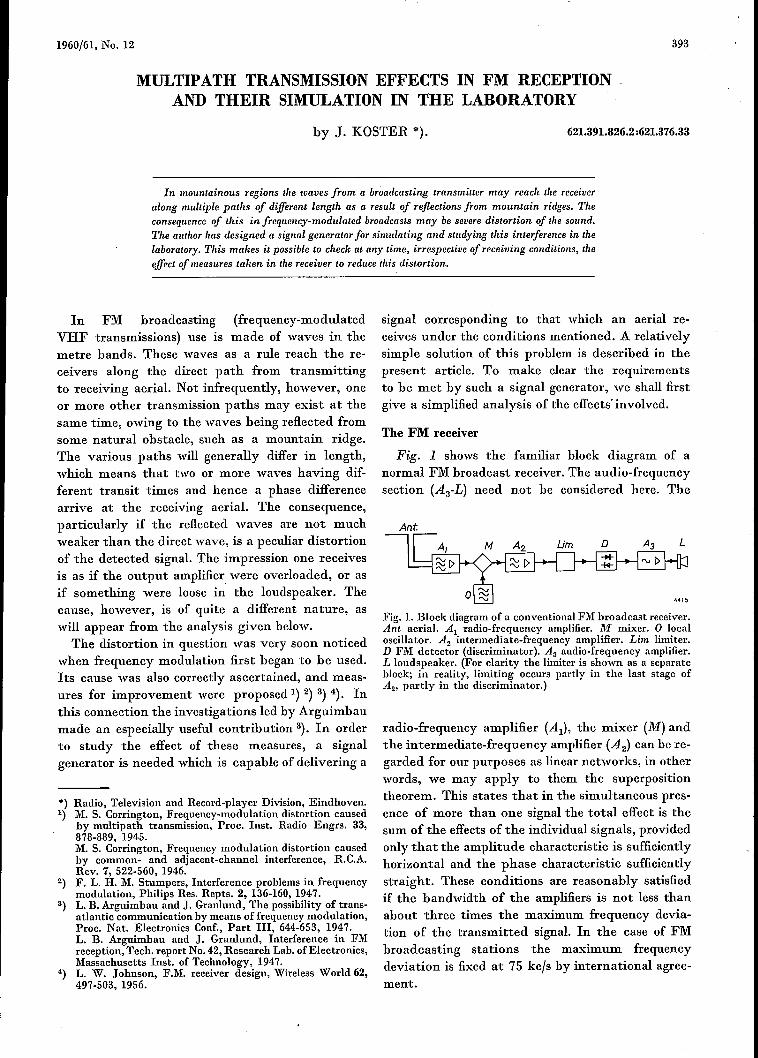
Fig. 1 shows the familiar block diagram of anormal FM broadcast receiver. The audio-frequencysection (A3-L) need not be considered here. The
Ant
Fig. 1. Block diagram of a conventional FM broadcast receiver.Ant aerial. Al radio-frequency amplifier. M mixer. 0 localoscillator. A2 intermediate-frequency amplifier. Lim limiter.D FM detector (discriminator). A3 audio-frequency amplifier.L loudspeaker. (For clarity the limiter is shown as a separatebloek; in reality, limiting occurs partly in the last stage ofA2' partly in the discriminator.)
radio-frequency amplifier (AI)' the mixer (M) andthe intermediate-frequency amplifier (A2) can be re-garded for our purposes as linear networks, in otherwords, we may apply to them the superpositiontheorem. This states that in the simultaneous pres-ence of more than one signal the total effect is thesum of the effects of the individual signals, providedonly that the amplitude characteristic is sufficientlyhorizontal and the phase characteristic sufficientlystraight. These conditions are reasonably satisfiedif the bandwidth of the amplifiers is not less thanabout three times the maximum frequency devia-tion of the transmitted signal. In the case of FMbroadcasting stations the maximum frequencydeviation is fixed at 75 kcfs by international agree-ment.
394. PHILlPS TECHNICAL REVIEW VOLUME 22
The limiter (Lim) and the discriminator (D) areessentially .non-linear systems. It is therefore notenough to consider each input signal individually;we must also take their resultant into account. Weshall see presently that in certain circumstances theinstantaneous frequency of the resultant signalmay make excursions far beyond the band withinwhich the instantaneous frequencies of the con-stituent signals remain. To meet these unfavourablecircumstances it is necessary to give the non-linearpart of the receiver a bandwidth larger than is need-ed for a normal FM signal.
Analysis of multipath transmission effects
In an article in the previous issue of this journalit was shown that an FM receiver to which two sig-nals are simultaneously applied will detect thestronger of the two, whilst the weaker one will actas an interfering signal 5). Multipath reception ofFM signals is to be treated as a special case of this.To avoid unnecessary complication of the problem,
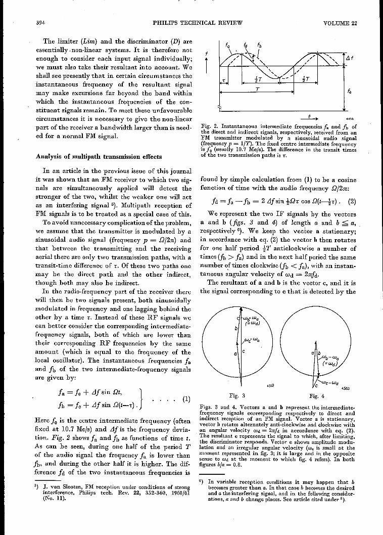
we assume that the transmitter is modulated by asinusoidal audio signal (frequency p = D/2n) andthat between the transmitting and the receivingaerial there are only two transmission paths, with atransit-time difference of r. Of these two paths onemay be the direct path and the other indirect,though both mayalso be indirect.
In the radio-frequency part of the receiver therewill then be two signals present, both sinusoidallymodulated in frequency and one lagging behind theother by a time r. Instead of these RF signals wecan better consider the corresponding intermediate-frequency signals, both of which are lower thantheir corresponding RF frequencies by the sameamount (which is equal to the frequency of thelocal oscillator). The instantaneous frequencies faand fb of the two intermediate-frequency signalsare given by:
fa = fo + LJfsin su. }fb = fo + LJf sin D(t--,;) .
Here fo is the centre intermediate frequency (oftenfixed at 10.7 Mc/s) and LJf is the frequency devia-tion. Fig. 2 shows fa and fb as functions of time t.As can be seen, during one half of the period Tof the audio signal the frequency fa is lower thanfb, and during the other half it is higher. The dif-ference fd of the two instantaneous frequencies is
ó) J. van Slooten, FM reception under conditions of stronginterference, Philips tech. Rev. 22, 352-360, 1960/61(No. ll).
f
Î/H
4416
Fig. 2. Instantaneous intermediate frequencies f« and fb ofthe direct and indirect signals, respectively, received from anFM transmitter modulated by a sinusoidal audio signal(frequencyp = lJT). The fixed centre intermediate frequencyis T« (usually 10.7 Mc/s). The difference in the transit timesof the two transmission paths is T.
found by simple calculation from (1) to be a cosinefunction of time with the audio frequency D/2n:
fd = fa - fb = 2 Llfsin i.Qc cos .Q(t---{c). (2)
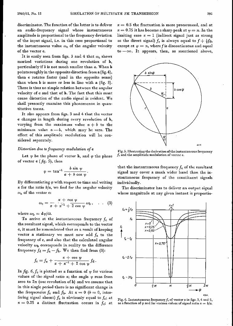
We represent the two IF signals by the vectorsa and b (figs. 3 and 4) of length a and b < a,respectively 6). We keep the vector a stationary;in accordance with eq. (2) the vector h then rotatesfor one half period iT anticlockwise a number oftimes (fb > fa) and in the next half period the samenumber of times clockwise (fb < fa), with an instan-taneous angular velocity of Wd = 2nfa.
The resultant of a and h is the vector c, and it isthe signal corresponding to c that is detected by the
o C
4562
(1) Fig.3 Fig.4
Figs. 3 and 4.. Vectors a and b represent the intermedia te-frequency signals corresponding respectively to direct andindirect reception of an FM signal. Vector a is stationary,vector b rotates alternately anti-clockwise and clockwisewithan angular velocity rod = 2n/d in accordance with eq, (2).The resultant c represents the signal to which, after limiting,the discriminator responds. Vector c shows amplitude modu-lation and an irregular angular velocity (wc is small at themoment represented in fig. 3; it is large and in the oppositesense to Wd at the moment to which fig. 4. refers). In bothfigures b]« = 0.8.
G) In variable reception conditions it may happen that bbecomesgreater than a. In that case b becomesthe desiredand a the interfering signal, and in the followingconsider-ations, a and b change places. See article cited under ó).
1960/61, No. 12 SIMULATION OF MULTIPATH FM TRANSMISSION 395
discriminator. The function ofthe latter is to deliveran audio-frequency signal whose instantaneousamplitude is proportional to the frequency deviationof the input signal, i.e, in this case proportional tothe instantaneous value Wc of the angular velocityof the vector c.
It is easily seen from figs. 3 and 4 that Wc showsmarked variations during one revolution of h,particularly if b is not much smaller than a. When hpoints roughly in the opposite direction from a (fig.4),then c rotates faster (and in the opposite sense)than when h is more or less in line with a (fig. 3).There is thus no simple relation between the angularvelocity of c and that of h. The fact that this mustcause distortion of the audio signal is evident. Weshall presently examine this phenomenon in quan-titative terms.It also appears from figs. 3 and 4 that the vector
c changes in length during every revolution of h,varying from the maximum value a + b to theminimum value a - b, which may be zero. Theeffect of this amplitude modulation will be con-sidered separately.
Distortion due to frequency modulation of c
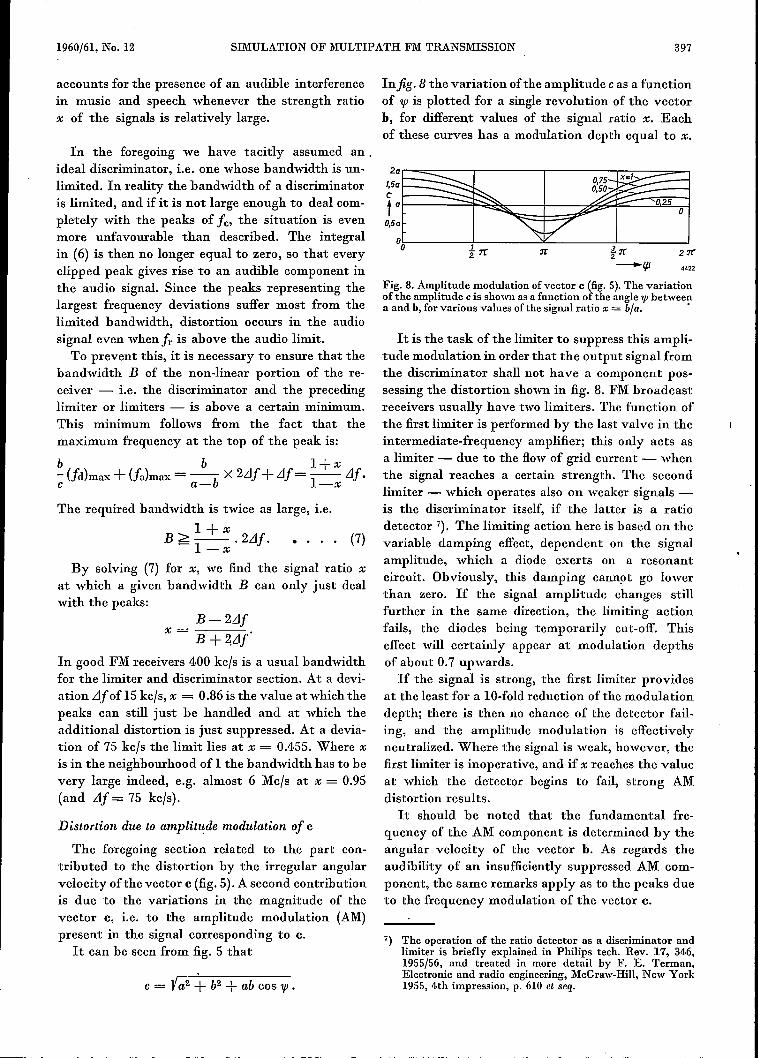
Let '1{J be the phase of vector h, and cp the phaseof vector c (jig. 5), then
b sin '1{Jcp = tan " ---:-----'-
a + b cos '1{J
By diffcrentiating cp with respect to time and writingx for the ratio bla, we find for the angular velocityWc of the vector c:
x + cos '1{JWc = 1 Wb, (3)
x + x + 2 cos '1{J
where Wb = d "P/dt.To arrive at the instantaneous frequency fc of
the resultant signal, which corresponds to the vectorc, it must he remembered that as a result of keepingvector a stationary we must now add fa to thefrequency of c, and also that the calculated angularvelocity Wb corresponds in reality to the differencefrequency îe = fa -fbo We then find from (3):
x + cos '1{Jfc = fa + + -1 . 2 fd .x x + cos '1{J
In jig. 6, fc is plotted as a function of 'If' for variousvalues of the signal ratio x; the angle '1{J runs fromzero to 2n (one revolution of h) and we assume thatin this single period there is no significant change inthe frequencies fa and fbo At x = 0 (b = 0, inter-fering signal absent) fc is obviously equal to fa; atx = 0.25 a distinct fluctuation occurs in fe; at
x = 0.5 the fluctuation is more pronounced, and atx = 0.75 it has become a sharp peak at '1{J = n, In thelimiting case x = 1 (indirect signal just as strongas the direct signal) fc is always equal to f + Hd,except at "P = n, where fis discontinuons and equalto - 00. It appears, then, as mentioned above,
441Q
Fig. 5. Illustrating the derivation oftheinstantaneous frequencyJe and the amplitude modulation of vector C.
that the instantaneous frequency I« of the resultantsignal may cover a much wider band than the in-stantaneous frequency of the constituent signalsindividually.
The discriminator has to deliver an output signalwhose magnitude at any given instant is proportio-
x=1
o
4564.
Fig. 6. Instantaneous frequency Je of vector c in figs. 3,4 and 5,as a function of 1jJ and for various values of signal ratio x = b]a,

396 PHILIPS TECHNICAL REVIEW VOLUME 22
nal to the instantaneous frequency deviation of theinput signal. For example, if the instantaneousfrequency fc of the input signal has the form shownby the curve for x = 0.75 in fig. 6, the output volt-age will have a form that corresponds to the fluctu-ation of fa (i.e. the original audio signal) except fora superimposed peak at 'lfJ = n in each period2n/wb of the vector b. The output signal will thenhave an appearance such as that infig. 7.
The number of peaks per period T is equal to thenumber, of complete revolutions of vector b (thevector a being stationary) in the time T.This numbercan he determined as follows.
4421
Fig. 7. Broken line: sinusoidal audio signal in undistortedreception. Solid line: with reception via two transmissionpaths, a peak occurs whenever the vector c (fig. 5) has a highangular velocity (1p "'" 180°). Such a waveform occurs whenthe phase difference of the modulations of the two receivedsignals is 180°.
We represent the phase of the signal that followsthe shorter transmission path by
Wa = m sin .Qt+ wot
and that of the other signal by
<Jib = m sin .Q(t-i) + wo(t-r') .
The instantaneous phase difference of the two signalsis then:
= 2m sin !.Qi cos .Q(t----ti) + WOi.
This phase difference, then, varies with time in ac-cordance with a cosine function, with the frequency.Q/2n. During the quarter period in which the cosineincreases from zero to 1, the phase difference changesaccording to (4) by an amount of 2m sin !.Qiradians. In a complete period T the variation there-fore amounts to Sm sin !.Qi radians. The numberof times that the vector b in the time T sweeps anangle of 2n radians (giving rise to one peak) is thus~ m sin !.Qi, and this occurs per second
fr = ! iJf sin !t:h times,n
since m = TiJf; the quantity Jr IS the averagerepetition frequency of the peaks.
Since the phase angle swept per period is generallynot an exact multiple of 2n, some peaks will not becompletely formed.
Because the frequency difference fd varies (seefig. 2 or eq. (2)), the repetition frequency fr of thepeaks fluctuates about the mean value Jr' given by(5). The peaks are farthest apart at the momentswhen fa = fb (i.e. at the points ,vhere the two sinewaves in fig. 2 intersect) and are closest togethermidway between these moments. A high pulse rateis associated with a large amplitude. During thetime!T in which j], is greater thanfa, the frequencydifference fd is negative and the peaks point up-wards; during the other half cycle they point down-wards (see fig. 7).
Concerning the numerical value of J~(eq. (5)) it isdifficult to be definite, since the factor sin !.Qiwith varying .Q can assume any value between zeroand 1. The frequency deviation ilf, which may goup to 75 kc/s, amounts on an average to no morethan about 15 kc/so In the most favourable case(sin !.Qi = 1) the value of Jr at the average devia-tion may lie near the threshold of audibility(20 kc/s), and exceeds it only when the deviationincreases. The repetition frequency fr fluctuates,as mentioned, around the mean value Jr, therebyvarying from zero to a value greater than fr. Evi-dently, therefore,fr can only be above the thresholdof audibility during a part of the period T. In thispart the peaks are generally crowded together. Apeak represents a frequency deviation, the meanvalue of which,]c, follows from eq. (3) (if we regardthe angular velocity Wb as constant during the shorttime in which a peak is formed):
'"- Wc Wb r x + cos 'lfJfc = -=- d'lfJ.
2 n 2n2., x + X-I + 2 cos 'lfJo
(6)
(4,) It can he shown that for x smaller than unity thisintegral is zero. This means that the peaks in thetime interval in question are practically inaudible.
What is the situation in practice? Apart from onthe transit-time difference i, the phase differencedepends on the audio frequency P» for at a low audiofrequency the phase varies less per unit time (andthus also in the time i) than at a high audio fre-quency. Since, in the spectrum of music and speech,numerous frequencies occur which are fairly uni-formly distributed over the audio range, there willalways be a great many phase differences, some ofthem small. This, together with the fact that theaverage frequèncy deviation is only about 15 k~/s,(5)
1960/61, No. 12 SIMULATION OF MULTIPATH FM TRANSMISSION 397
accounts for the presence of an audible interferencein music and speech whenever the strength ratiox of the signals is relatively large.
In the foregoing we have tacitly assumed an.ideal discriminator, i.e. one whose bandwidth is un-limited. In reality the bandwidth of a discriminatoris limited, and if it is not large enough to deal com-pletely with the peaks of fe, the situation is evenmore unfavourable than described. The integralin (6) is then no longer equal to zero, so that everyclipped peak gives rise to an audible component inthe audio signal. Since the peaks representing thelargest frequency deviations suffer most from thelimited bandwidth, distortion occurs in the audiosignal even when fr is above the audio limit.To prevent this, it is necessary to ensure that the
bandwidth B of the non-linear portion of the re-ceiver - i.e, the discriminator and the precedinglimiter or limiters - is above a certain minimum.This minimum follows from the fact that themaximum frequency at the top of the peak is:
b b I+x- (fd)max + (fa)max = -- X 2IJf + IJf = _- IJf·c a-b I-x
The required bandwidth is twice as large, i.e.
I+xB>--.2IJf·-I-x
By solving (7) for x, we find the signal ratio xat which a given bandwidth B can only just dealwith the peaks:
B- 2IJfx=----
B + 2.IJfIn good FM receivers 400 kc/s is a usual bandwidthfor the limiter and discriminator section. At a devi-ation IJf of 15kc/s, x = 0.86 is the value at which thepeaks can still just be handled and at which theadditional distortion is just suppressed. At a devia-tion of 75 kc/s the limit lies at x = 0.4055. Where xis in the neighbourhood of 1 the bandwidth has to bevery large indeed, e.g. almost 6 Mc/s at x = 0.95(and IJf = 75 kc/s).
Distortion due to ompiitude modulation of c
The foregoing section related to the part con-tributed to the distortion by the irregular angularvelocity ofthe vector c (fig. 5). A second contributionis due to the variations in the magnitude of thevector c, i.e. to the amplitude modulation (AM)present in the signal corresponding to c.
It can be seen from fig. 5 that
c = Va2 -+ b2 + ab cos "p •
In fig. 8 the variation of the amplitude c as a functionof "p is plotted for a single revolution of the vectorh, for different values of the signal ratio x. Eachof these curves has a modulation depth equal to x.
i~~o frr rr t~ 2rr
-lp 4422
Fig. 8. Amplitude modulation of vector c (fig. 5). The variationof the amplitude c is shown as a function of the angle 1fl betweena and h, for various values of the signal ratio x = bla. •
(7)
It is the task of the limiter to suppress this ampli-tude modulation in order that the output signal fromthe discriminator shall not have a component pos-sessing the distortion shown in fig. 8. FM broadcastreceivers usually have two limiters. The function ofthe first limiter is performed by the last valve in theintermediate-frequency amplifier; this only acts asa limiter - due to the flow of grid current - whenthe signal reaches a certain strength. The secondlimiter - which operates also on weaker signals -is the discriminator itself, if the latter is a ratiodetector 7). The limiting action here is based on thevariable damping effect, dependent on the signalamplitude, which a diode exerts on a resonantcircuit. Obviously, this damping cannot go lowerthan zero. If the signal amplitude changes stillfurther in the same direction, the limiting actionfails, the diodes being temporarily cut-off. Thiseffect will certainly appear at modulation depthsof about 0.7 upwards.If the signal is strong, the first limiter provides
at the least for a IO-fold reduction ofthe modulationdepth; there is then no chance of the detector fail-ing, and the amplitude modulation is effectivelyneutralized. Where the signal is weak, however, thefirst limiter is inoperative, and if x reaches the valueat which the detector begins to fail, strong AMdistortion results.It should be noted that the fundamental fre-
quency of the AM component is determined by theangular velocity of the vector b. As regards theaudibility of an insufficiently suppressed AM com-ponent, the same remarks apply as to the peaks dueto the frequency modulation of the vector c.
7) The operation of the ratio detector as a discriminator andlimiter is briefly explained in Philips tech. Rev. 17, 346,1955/56, and treated in more detail by F. E. Terman,Electronic and radio engineering, McGraw-Hill, New York1955, 4th impression, p. 610 et seq.

398 PHILIPS TECHNICAL REVIEW VOLUME 22
The great importanee of good AM suppressionmay be understood by considering the ease whereAM is not suppressed at all. The low-frequency volt-age generated in the diseriminator by the amplitudemodulation of c is then found to be roughly 15xtimes higher than the undistorted signal that thediseriminator should give (for a frequency deviationof 15 kc/s). Even if x is only 0.1, the AM inter-ference is still 1.5 times stronger than the desiredaudio signal. On the other hand, where the receiverbandwidth is adequate and the values of x are small,but otherwise under the most unfavourable con-ditions, the interferenee due to frequency modula-tion of c is only 0.2x times the undistorted audiosignal. To reduce the total interferenee it is there-fore of paramount importance to have adequateAM suppression.
MeasUl'esfor reducing FM distortion due to multipathtransmission
From the fact that the distortion diseussed in-ereases in severity the closer the signal ratio x =b/ a approaches unity, it follows that our first eounter-measure must be to try to reduee x. For this purposean aerial having a sharp directional effect should beused, positioned in such a way that x is minimum.
The measures to be taken in the receiver itselfeonsist, as follows from the above eonsiderations, ingiving the limiter and discriminator seetion a largebandwidth, in ensuring rigorous limiting, and indesigning a discriminator capable of handling signalratios close to unity.
This article is not eoncerned with the means bywhich these requirements can be met. In the nextsection, however, we shall describe a signal gener-ator designed to simulate the aerial signal resultingfrom multipath transmission. With this signalgenerator it is possible to study the effect of theabove-mentioned measures to reduee distortion,even in plaees where there are no suitable reflectingobstacles in the neighbourhood.
A signal generator for simulating multipath trans-mission effects in FM reception
The investigators cited in footnotes 1) and 3)studied these effects experimentally as well as theo-retically. They conducted the radio-frequency FMsignal, produced in a generator, along two pathsto the receiver under investigation: along a shortdirect path and along a path having an appreciabledelay time. For this second path Corrington used acoaxial cable which had to be more than 3 km longto give a transit time of 16 (J.sec- corresponding toa detour in the "ether" ofless than 5 km. Arguimbau
and Granlund, by piezo-electric means, first con-verted the radio-frequency signal into an ultrasonicvibration; they passed this through _a mercurycolumn, at the end of which they converted it back
. again into an electrical signal. Neither of thesemethods is convenient if the apparatus is requiredto be compact and ,portable. For these reasons wehave adopted a different approach to the problem.
Two radio-frequency signals have to be generated,namely a "direct" signalof instantaneous frequencyFa:
Fa = Fo + LJfsin ûi ,
and a "reflected" signalof instantaneous frequencyFb:
Fb = Fo + LJfsin D(t-7:) .
Here Fo is the centre frequency, and there is onlyone audio frequency (= D/2n). Introducing anangle a which satisfies
a = IDt - 2nnl < 2n ,
where n is an integer, we can write the formula forFb as
Fb = Fo + LJfsin (Dt - a) .
The two radio-frequency signals can thus in prin-ciple be obtained by using the same audio signal tofrequency-modulate two signal generators havingthe same centre frequency Fo, the "delayed" signalbeing made to lag the "direct" signal by a phaseangle a. The latter is produced by a phase shifterwhich will presently be discussed.
In actual FM reception the transit-time difference T givesrise not only to a phase difference a between the modulations,but also to a phase differenceWo T between the radio-frequencysignals; see eq. (4). In order to simulate the latter phase dif-ference, use might he made of a second phase shiftcr, nowfor high frequencies.We have not done this, however, since theonly effect of the phase angle Wo T consists in a displacementof the peaks in fig. 7 over less than the width of onc peak.This displacement is of no importance to the study of multi-path distortion. .
With two separate oscillators it is not possibleto satisfy the condition that the two modulatedsignals shall have the same centre frequency. Onecommon oscillator must therefore be used. Fre-quency modulation, however, can only be intro-duced in the oscillator itself; modulating this (infrequency) by two different audio signals would beno use whatsoever, for it would not yield the re-quired two radio-frequency signals each modulatedby one of the audio signals.

1960f61,No. 12 SIMULATION OF MULTIPATH FM TRANSMISSION
A system free from this limitation is phase modu-lation, for here the modulation can be appliedafter the oscillator. Phase modulation was thereforethe system we decided to adopt. A phase-modulatedsignal, however, differs from a frequency-modulatedsignal in that the frequency deviation is propor-tional not only to the amplitude of the audio signalbut also to the audio frequency. In order to makethe result of phase modulation identical with thatof frequency modulation, the audio signal is passedthrough an integrating network; this delivers anoutput voltage which is inversely proportional tothe audio frequency.
Block diagram
The block diagram of the signal generator isshown infig. 9. The oscillator 01' whose frequency is
and a phase shifter P preceding the integrator hprovides the variable phase angle a. We shall returnin a moment to the circuit arrangements to permitmodulation by music and speech.
Following the normal practice in FM transmitters,the maximum frequency deviation is brought tothe required 75 kc/s by frequency multiplication.This is done in the stages Mual, Mua2, MUbl andMUb2'
For this purpose the total multiplication factor needed ismore than 400. A factor of about 30, however, is sufficient toraise the frequency of Ol (3 Mcfs) to a value within the FMbroadcast band (87.5-100 Mcfs). For this reason 18-foldmultiplication is applied in 111uOI and MUbl' after which, bymixing with an auxiliary frequency of 50 Mcfs, the centrefrequency is reduced from 54 to 4 Mcfs, the 18-fold frequencydeviation being retained. In 1\<Iun2 and 111ub2 a 24-fold mul-
4424
Fig. 9. Block diagram of apparatus for simulating FM multipath reception. Subscripts arelate to the "direct" signal, subscripts b to the "reflected" signal.
Ol 3 Mcfs crystal oscillator. BUI' Bbl buffer stages. G signal generator (type GM 2315).P phase shifter. I«; h integrating networks. PMa, PAIb phase modulators. Munl, MUhlfrequency multipliers (18x). O2 50 Mcfs crystal oscillator. B02' Bb2 buffer stages.Ma, Mb mixing stages. Mu1I2, AII£b2 frequency multipliers (24x). Au.; AUb continuouslyvariable "ladder" attenuators. N matching network. The aerial terminals of the receiverare connected to the output ofN.
controlled by a quartz crystal, gives an output hav-ing a constant frequency of 3 Mc/s. In the phasemodulators PMa and PMb the oscillator output ismodulated in phase by an audio signal which isapplied to the modulators through the above-mentioned integrating networks, la and lb, Twobuffers Bal and Bbl> each consisting of a simplepentode stage, prevent feedback from the phasemodulators to the oscillator.
Fig. 9 refers to the case of a sinusoidal audiosignal. This is delivered by the signal generator G,
tiplication is then applied, which raises the centre frequencyfrom 4 to 96 Mcfs and brings the total multiplication of thedeviation to 18X24 = 432.The auxiliary frequency of50Mcfsis generated by the crystal
oscillator O2, and mixing is done in the stages Aia and Aib.The buffers (pentode stages) Ba2 and Bb2 prevent undesiredcoupling between the channels via 02'The mixing process would not be necessary if the frequency
of Ol were low enough (e.g. 220 kcfs) to allow the same highmultiplication factor used for the frequency deviation to beapplied for the central frequency. A frequency as low as thisfor Ol' however, would have entailed considerable difficul-ties with the bandwidth.
399
4·00 PHILIPS TECHNICAL REVIEW VOLUME 22
At the outputs of the multipliers MUa2 and MUb2a continuously variable attenuator is connected(Atta and Attb' respectively); this is a so-called"ladder" attenuator, which has the property thatthe impedance remains constant (here 50 ohms),whatever the attenuation. Through coaxial cables,whose characteristic impedance is likewise 50 ohms,both signals are conducted to a matching networkN, which terminates the cables with 50 ohms andshows the same impedance at its output. Here theterminals of the receiver are connected.
The circuit shown in fig. 10 makes it possible toshift the sinusoidal modulation of the "reflected"
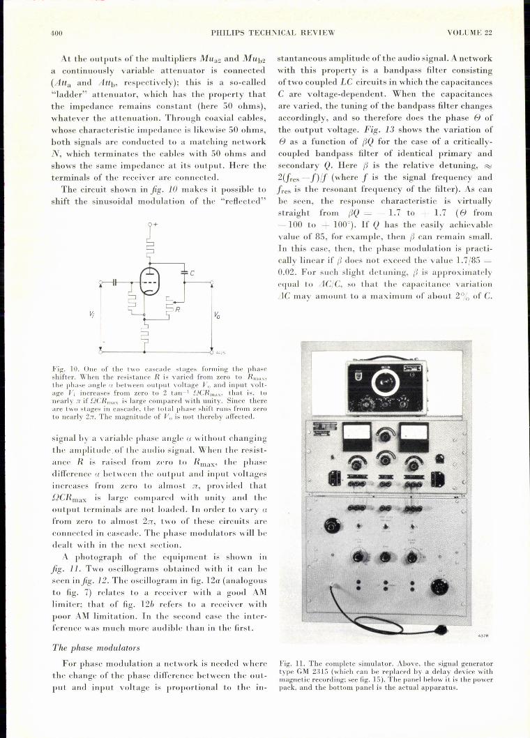
Fig. 10. One of the two cascade stages forming the phaseshif'ter. \Vhen tbe resistance R is varied from zero to R",,,,,the phase angle !1 between output voltage Vo and input volt-age Vi increases from zero to 2 tan 1 DCR",,,,, that is, tonearly :7 if DCR",,,, is large compared with unity. Since thereare two stages in cascade. the total pbase shift runs frorn zeroto nearly 2:7. The magni tude of V" is not thereby affected.
signal by a variable phase angle a without changingthe amplitude. of the audio signal. When the resist-auce R is raised from zero to Rmax, the phasedifference a between the output and input voltagesincreases from zero to almost ie, provided that.QCRmax is large compared with unity and theoutput terminals are not loaded. In order to vary afrom zero to almost 2n, two of these circuits areconnected in cascade. The phase modulators will bedealt with in the next section.
A photograph of the equipment IS shown infig. 11. Two oscillograms obtained with it can bcseen infig. 12. The oscillogram in fig. 12a (analogousto fig. 7) relates to a receiver with a good AMlimiter; that of fig. 12b refers to a receiver withpoor AM limitation. In the second case the inter-ference was much more audible than in thc first.
The phase modulators
For phase modulation a network is needed wherethe change of the phase difference between the out-put and input voltage is proportional to the in-
stantaneous amplitude of the audio signal. A networkwith this property is a bandpass filter consistingoftwo coupled LC circuits in which the capacirancesC are voltage-dependent. When the capacitancesare varied, the tuning of the bandpass filter changesaccordingly, and so therefore does the phase e ofthe output voltage. Fig. 13 shows the variation ofe as a function of {JQ for the case of a critically-coupled bandpass filter of identical primary andsecondary Q. Here {J is the relative detuning, ~2(fres - f)lf (where f is the signal frequency andfr es is the resonant frequency of the filter). As canbe seen, the response characteristic is virtuallystraight from {JQ = - 1.7 to + 1.7 (e from- 100 to + 100°). If Q has the easily achievablevalue of 85, for example, then {J can remain small.In this case, then, the phase modulation is practi-cally linear if {J does not exceed the value 1.7/85 =0.02. For such slight detuning, {J is approximatelyequal to LICjC, so that the capacitance variationL1Cmay amount to a maximum of about 2% of C.
4376
Fig. 11. The complete simulator. Above, the signal generatortype GM 2315 (which call be replaced by a delay device withmagnetic recording; see fig. 15). The panel below it is the powerpack, and the bottom panel is the actual apparatus.

1960/61, No. 12 SIMULATION OF MULTIPATH FM TRANSMISSION 4·01
Fig. 12. OsciJlograms of the output voltage from the discriminator in an FM receiverconnected to the simulator described. The modulation was sinusoidal. a) Receiver withsatisfactory AM limiting (cf. fig. 7). b) Receiver with inadeqnate AM limiting.
a
Semiconductor diodes in the cut-off state behaveas voltage-dependent capacitances. The capacitanceC depends in the following way on the appliedreverse voltage V:
where Kl and K2 are diode constants (K2 IS nega-
180e ---I--1'20 .>60
-J -2 -I 01/ I-:0 I 2 J
60-f3Q
V -120-!------"'-180 44-26
Fig. 13. Phase variation e of the output voltage from acritically-coupled bandpass filter having an identical primaryand secondary Q factor, as a function of Q times the relativede tuning {J.
tive). Fig. 14 shows the variation of C with voltageV measured on a silicon diode.If a small alternating voltage is snperposed on the
direct voltage V, the change of C is roughly pro-portional to the alternating voltage. This principleis applied in the phase modulators PMa and PMb(fig. 9).
b
Modulation by music or speech
In order to make the distorted output signalfrom the receiver visible in an oscillogram, theobvious method is to modulate with a sinusoidalaudio signal; this case is represented in the blockdiagram in fig. 9.After the signal generator haelbeen thus designed,
however, the nced arose for some means of judgingby ear the quality of received music or speech whenthe distortion described is present. For this purposethe apparatus was extended with a deviee for modu-lating by music or speech. The signal generatoranel the phase shifter are then put out of action -the latter because the phase angle a it delivers is notproportional to the audio frequency, which means
/OOpF
80
1\~
I'---r-- -40
20
-5 -10 -f5V-V 4427
Fig. 14. Measured capacitance C of a silicon diode as a functionof the DC reverse voltage V.
402 PHILIPS TECHNICAL REVIEW VOLUME 22
CIRCULAR OPTICAL ABSORPTION WEDGES
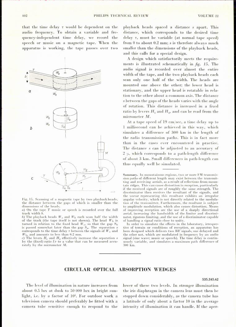
that the time delay T would be dependent on theaudio frequency. To obtain a variable and fre-quency-independent time delay, we record thespeech or mUSICon a magnetic tape. When theapparatus IS working, the tape passes over two
b
c
Fig. IS. Scanning of a magnetic tape by two playbackheads,the distance between the gaps of which is smaller than thedimensions of the heads.a) On the tape T music or speech is recorded over the fulltrack width b.b) The playback heads Wa and rr"b each scan half the widthof the track (the tape itself is not shown). The head Wh isturned in relation to the fixed head W,,, so that the gap Sbis passed somewhat later than the gap Sa. The separation scorresponds to the time delay r between the signals of Wa andWh, and amounts to less than 0.2 mm.c) The levers H, and H2 effectively increase the separation sby the (fixed) ratio liT to a value that can be measured accu-rately by the micrometer M.
The level of illumination in nature increases fromabout 0.5 lux at dusk to 50 000 lux in bright sun-light, i.e. by a factor of 105• For outdoor work atelevision camera should preferably be fitted with acamera tube scnsitive enough to respond to the
playback heads spaced a distance s apart. Thisdistance, which corresponds to the desired timedelay T, must be variable (at normal tape speed)from 0 to about 0.2 mm; s is therefore always muchsmaller than the dimensions of the playback heads,and this calls for a special design.A design which satisfactorily meets the require-
ments is illustrated schematically in fig. IS. Theaudio signal is recorded over almost the entirewidth of the tape, and the two playback heads eachscan only one half of the width. The heads aremounted one above the other; the lower head isstationary, and the upper head is rotatable in rela-tion to the other about a common axis. The distances between the gaps of the heads varies with the angleof rotation. This distance is increased in a fixedratio by levers HI and H2' and can be read from themicrometer M.At a tape speed of 19 cm/sec, a time delay up to
1 millisecond can be achieved in this way, whichsimulates a difference of 300 km in the length ofthe radio transmission paths. This is in fact morethan in the cases ever encountered in practice.The distance s can be adjusted to an accuracy of2 [L, whieh corresponds to a path-length differcnceof about 3 km. Small differences in path-length canthus equally well be simulated.
.!.l._'8
Summary. In mountainous regions, two or more FM t.ransmis-sion paths of different length may exist between the transmit-ting and receiving aerials, as a result of reflections from IHOUll-
tain ridges. This can cause distortion in reception, par ticularl yif the received signals are of roughly the same strength. Thediscriminator t hen receives the resultant of tbe signals, andthe vector reprcsenting this resultant exhibits an irregularangular velocity, which is no t directly related to the modula-tion of the transmitter. Furthermore, the resultant is subjectto amplitude modulation, which also canses distortion. Meansof improving reception are the use of a sharply directionalaerial, increasing the bandwidth of the limiter and discrirni-nator, rigorous limiting, and the use of a discriminator capableof handling a signal ratio close to unity.
In order to simulate the effects in the laborator y, irrespec-tive of terrain or conditioris of reception, an apparatus hasbeen designed which delivers two RF signals, one delayed andthe other not, which are modulated in frequency by an audiosignal (sine wave; music or speech). The time delay is contin-uously variable, and simulates a maximum path difference of300 km.
535.345.62
lower of these two levels. In stronger illuminationthe iris diaphragm in the camera lens must then bestopped down considerably, as the camera tube hasa latitude of only about a factor 10 in the averageintensity of illumination it can handle. If the aper-


