multimedia - Matrix TSL€¦ · If you are using Fischertechnik then you will need to refer to the...
14
matrix multimedia Experiment plans for control technology Document contents Introduction 1. Calibrating a sensor 2. Simple control programs 3. Programs with Analogue feedback
Transcript of multimedia - Matrix TSL€¦ · If you are using Fischertechnik then you will need to refer to the...

matrixmultimedia
Experiment plans for control technology
Document contents
Introduction 1. Calibrating a sensor 2. Simple control programs 3. Programs with Analogue feedback
Introduction This document has been written to give practical ideas of how to use Flowlog in teaching simple control technology. It can be used in conjunction with the course outline plan for teaching control and datalogging. In this document we have assumed that you will be using Flowlog with a Fischertechnik starter kit or an Analogue Feedback System. Flowlog offers other opportunities for presenting students with control problems: the Control cards provide a framework for particular problems including:
1. Light switch control 2. Sound level indicator 3. Elevator control 4. Hand dryer model 5. Car park barrier 6. Pedestrian crossing 7. Automatic door
Items 4 to 7 are also supported by Fischertechnik models which students can get working with the Flowlog. If you are using Fischertechnik then you will need to refer to the instruction guide for building the models entitled “Computing starter Assembly instructions”. Other resources that you will find useful include:
• Flowlog ‘how to…’ videos on the Flowlog installation disk • Analogue Feedback Systems datasheet
These experiments can be used for both Flowlog Lite and the Standard Flowlog – these plans assume that you are using a standard Flowlog. Please do give us your feedback on the usefulness of these experiment plans. John Dobson Managing Director Matrix Multimedia Limited 060803

Calibrating a sensor Experiment plan
1 Calibrating a sensor
Learning Objectives • To understand the basic electronics behind a simple analogue sensor • To understand how to select and calibrate a sensor • To understand the electrical characteristics of a sensor • To understand how to make and use a sensor • Understand errors in calibration
Equipment List Flowlog Analogue feedback system, or separate thermistor potential divider circuit with good thermal coupling to a temperature probe. Temperature probe 5V power supply (optional)
Background information You will need to introduce students to the following concepts:
• Simple sensor potential divider circuit • PTC/NTC thermistor operation • How a voltage is converted to a value - look up tables and calculation
Our solution to this experiment is:
This is approximate but sufficiently accurate for our purposes. We raised the temperature with a simple control program – put the temperature probe next to the sensor and assumed perfect thermal connectivity – a big assumption. This exercise does not need to be rigorous – students just need to understand the process of calibration and they will need values of voltage 1 against temperature on later worksheets. Voltage on v1 temperature 1.56 25 1.37 30

Calibrating a sensor Experiment plan
1.23 35 1.1 40 0.97 45 0.85 50

Calibrating a sensor Student worksheet
Student Worksheet - Simple sensor calibration Note – this worksheet will need customising for your own purposes. Background This experiment allows you to understand how sensors work and how a computer system calibrates sensors. Equipment List Flowlog Analogue feedback system, or Fischertechnik hand dryer model or separate thermistor potential divider circuit Temperature probe 5V power supply (optional) Summary In this experiment you will be heating up a sensor, which forms part of a potential divider chain, and you will be monitoring the voltage produces at the resistor/sensor junction at the same time as monitoring the temperature rise with a calibrated sensor. By producing a table of values of the voltage produced against the recorded actual temperature you can make a table which calibrates your sensor. Setting up the equipment Set up the Flowlog and the Analogue Feedback System as follows:
1
2
3
4
V1
V2
1
2
3
4
LIGHT SOUND
Power
EX
TE
RN
AL
DIG
ITAL
r5.4
r5.4
r5.4
r5.4r5.4
r4.6r5.4 r5.4
r4.6r5.4 r5.4
r4.6r5.4r5.4
r4.6 r8 r8
EX
TE
RN
AL
AN
ALO
GU
E 1
EX
TE
RN
AL
AN
ALO
GU
E 2
a b
c
h
n
p
r
t
m
datalogging control electrical measurementd
e f
g
l
i j
k
o
q
s
TEMP.
INPUTSPOWER
OUTPUTS
5VV
Power supply
Make sure the temperature probe is plugged into the Flowlog system and that the temperature probe is well inserted into the metal block inside the Analogue Feedback System. Procedure
1. Read the datasheet on the Analogue Feedback System and make sure you understand how the fan, heater and sensor are connected and how they operate.
2. Start a new live graph which monitors the external temperature at the same time as monitoring the voltage on V1 – the potential divider chain junction.
3. Write a simple control program that turns the heater on – no time limit. 4. Start both the control program and the live graph 5. Monitor the results until the temperature stops rising – about 10 minutes should do 6. Save your results.
Analysis and further work
1. Produce a table showing the input analogue voltage against recorded temperature. You can export the data to Excel to make this easier
2. Write a short report that highlights what errors there may be in these results and what you might do in an industrial setting to reduce these errors

Calibrating a sensor Student worksheet
3. Modify your control program so that it monitors temperature and voltage for a rising and a falling temperature. Compare the results with the previous data. What are the differences and why? Write a new control program to test your hypothesis.
4. How would you alter any programs you write to alleviate the shortcomings in sensor systems?
Simple control programs Experiment plan
2 Simple control programs
Learning Objectives • Digital control systems • Inputs and outputs • Flowlog commands
o Repeat….until o Input o Output o Delay
Equipment List Flowlog Analogue feedback system, or Fischertechnik hand dryer model
Connections Analogue Feedback system Output 1(n) to heater positive Output 1(m) to heater negative Output 2(p) to fan positive Output 2(o) to fan negative Fischertechnik hand dryer Note that output 1 is the heater, Output 2 is the fan and voltage 1 is the sensor input.
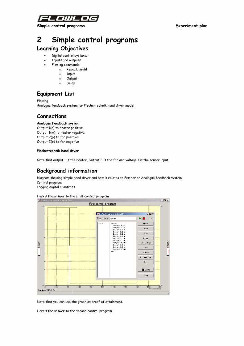
Background information Diagram showing simple hand dryer and how it relates to Fischer or Analogue feedback system Control program Logging digital quantities Here’s the answer to the first control program
Note that you can use the graph as proof of attainment. Here’s the answer to the second control program

Simple control programs Experiment plan

Simple control programs Student worksheet
Student Worksheet - Simple control programs Note – this worksheet will need customising for your own purposes. Background This experiment allows you to understand how a simple open loop control system can be programmed using Flowlog.. Equipment List Flowlog Analogue feedback system, or Fischertechnik hand dryer model. Summary In this experiment you will need to design a simple control program that turns outputs on and off at certain time intervals. Setting up the equipment If you are using Fischertechnik: Make the hand dryer model as shown in the Computing Starter guide. Make the connections to the Flowlog as shown in the diagram below (you will need the thermistor and resistor for the next experiment):
1
2
3
4
V1
V2
1
2
3
4
LIGHT SOUND
Power
EX
TE
RN
AL
DIG
ITAL
r5.4
r5.4
r5.4
r5.4r5.4
r4.6r5.4 r5.4
r4.6r5.4 r5.4
r4.6r5.4 r5.4r4.6 r8 r8
EX
TE
RN
AL
AN
ALO
GU
E 1
EX
TE
RN
AL
AN
ALO
GU
E 2
a b
c
h
n
p
r
t
m
datalogging control electrical measurementd
e f
g
l
i j
k
o
q
s
TEMP.
INPUTSPOWER
OUTPUTS
Phototransistor
Sensorbeam
Fan motor
Hand dryer
Light beam
5VV
Power supply
Thermistor
Resistor
bulb/heater
motor/fan
If you are using the Analogue Feedback system:

Simple control programs Student worksheet
1
2
3
4
V1
V2
1
2
3
4
LIGHT SOUND
Power
EX
TE
RN
AL
D
IGITA
L
r5.4
r5.4
r5.4
r5.4r5.4
r4.6r5.4 r5.4
r4.6r5.4 r5.4
r4.6r5.4 r5.4r4.6 r8 r8
EX
TE
RN
AL
AN
ALO
GU
E 1
EX
TE
RN
AL
A
NA
LOG
UE
2
a b
c
h
n
p
r
t
m
datalogging control electrical measurementd
e f
g
l
i j
k
o
q
s
TEMP.
INPUTSPOWER
OUTPUTS
5VV
Power supply
Note that we will use the analogue sensor in the next worksheet. Procedure - First control program Make a control program to mimic a simple industrial control system that:
1. Turns the heater on 2. Turns the fan on 3. Waits for 30 seconds 4. Turns the heater off 5. Waits for 10 seconds whilst the heater cools down 6. Turns the fan off
Develop this program in Flowlog Control and prove that it has worked using the Live Graph mode. You will need to use the Output and Delay commands only. Procedure - Second control program You will need to make a control program that:
1. Waits for button 1 to be pressed 2. Turns the fan on 3. Waits for 30 seconds 4. Turns the heater off 5. Waits for 10 seconds whilst the heater cools down 6. Turns the fan off
Develop this program in Flowlog Control and prove that it has worked using the Live Graph mode. You will need to use the commands in the first control program as well as the Repeat…until command.

Control with analogue feedback Experiment plan
3 Control with analogue feedback Learning Objectives
• Closed loop control systems • That there are different types of input: analogue and digital • Flowlog commands
o If…then…else o Loop….
Equipment Flowlog Analogue feedback system, or Fischertechnik hand dryer model with potential divider chain
Connections If you are using Fischertechnik:
1
2
3
4
V1
V2
1
2
3
4
LIGHT SOUND
Power
EX
TE
RN
AL
DIG
ITAL
r5.4
r5.4
r5.4
r5.4r5.4
r4.6r5.4 r5.4
r4.6r5.4 r5.4
r4.6r5.4r5.4
r4.6 r8 r8E
XT
ER
NA
L A
NA
LOG
UE
1E
XT
ER
NA
L A
NA
LOG
UE
2
a b
c
h
n
p
r
t
m
datalogging control electrical measurementd
e f
g
l
i j
k
o
q
s
TEMP.
INPUTSPOWER
OUTPUTS
Phototransistor
Sensorbeam
Fan motor
Hand dryer
Light beam
5VV
Power supply
Thermistor
Resistor
bulb/heater
motor/fan
Here you can see the connections you need to make to the Flowlog: The heater or bulb is attached to output 1, the fan motor is attached to output 2, and the voltage 1 input is attached to the junction of the thermistor and the resistor. If you are using Fischertechnik then you will need to construct the Hand dryer model which will suffice for this exercise. If you are using the Analogue Feedback System~:

Control with analogue feedback Experiment plan
1
2
3
4
V1
V2
1
2
3
4
LIGHT SOUND
Power
EX
TE
RN
AL
D
IGITA
L
r5.4
r5.4
r5.4
r5.4r5.4
r4.6r5.4 r5.4
r4.6r5.4 r5.4
r4.6r5.4 r5.4r4.6 r8 r8
EX
TE
RN
AL
AN
ALO
GU
E 1
EX
TE
RN
AL
AN
ALO
GU
E 2
a b
c
h
n
p
r
t
m
datalogging control electrical measurementd
e f
g
l
i j
k
o
q
s
TEMP.
INPUTSPOWER
OUTPUTS
5VV
Power supply
Use of a 5V power supply is optional – you can rig up one of the outputs of Flowlog to power the potential divider chain but the calibration results will be different if you used a 5V supply earlier. This worksheet is geared around the use of Standard Flowlog. This worksheet can still be used with Flowlog Lite – you can also use the 5V output on Flowlog Lite for the sensor circuit power.
Background information Before asking students to do this exercise you may want to introduce them to topics as follows:
• Advantages of analogue over digital • Diagram showing sensor circuit and an explanation of how sensors work electrically • Flow diagrams of feedback systems
Here’s our answer to the problem:

Control with analogue feedback Student worksheet
Student Worksheet - First control program Note – this worksheet will need customising for your own purposes. Background This experiment allows you to understand how a closed loop control system can be programmed using Flowlog.. Equipment List Flowlog Analogue feedback system, or Fischertechnik hand dryer model. Summary In this experiment you will need to design control program that keeps the temperature of a simulated industrial heater constant. Setting up the equipment If you are using Fischertechnik: Make the hand dryer model as shown in the Computing Starter guide. Make the connections to the Flowlog as shown in the diagram below (you will need the thermistor and resistor for the next experiment):
1
2
3
4
V1
V2
1
2
3
4
LIGHT SOUND
Power
EX
TE
RN
AL
DIG
ITAL
r5.4
r5.4
r5.4
r5.4r5.4
r4.6r5.4 r5.4
r4.6r5.4 r5.4
r4.6r5.4 r5.4r4.6 r8 r8
EX
TE
RN
AL
AN
ALO
GU
E 1
EX
TE
RN
AL
AN
ALO
GU
E 2
a b
c
h
n
p
r
t
m
datalogging control electrical measurementd
e f
g
l
i j
k
o
q
s
TEMP.
INPUTSPOWER
OUTPUTS
Phototransistor
Sensorbeam
Fan motor
Hand dryer
Light beam
5VV
Power supply
Thermistor
Resistor
bulb/heater
motor/fan
If you are using the Analogue Feedback system set up the equipment as follows:

Control with analogue feedback Student worksheet
1
2
3
4
V1
V2
1
2
3
4
LIGHT SOUND
Power
EX
TE
RN
AL
D
IGITA
L
r5.4
r5.4
r5.4
r5.4r5.4
r4.6r5.4 r5.4
r4.6r5.4 r5.4
r4.6r5.4 r5.4r4.6 r8 r8
EX
TE
RN
AL
AN
ALO
GU
E 1
EX
TE
RN
AL
AN
ALO
GU
E 2
a b
c
h
n
p
r
t
m
datalogging control electrical measurementd
e f
g
l
i j
k
o
q
s
TEMP.
INPUTSPOWER
OUTPUTS
5VV
Power supply
Procedure Your task here is to design a control program to mimic a simple heating system that maintains the internal temperature of the heating element constant. The algorithm you need to implement is as follows:
1. Wait until button 1 is pressed 2. turn the heating element on and wait until a temperature of 45 degrees has been reached. 3. maintain the temperature between 40 and 45 degrees using the fan only
You need to develop this program in Flowlog Control and prove that it has worked using the Live Graph mode. You will need to use the commands in the previous tutorial as well as If…then…else If you have not calibrated the sensor in a previous experiment then you will need to choose two voltage levels that the sensor produces and use these as your control values. Further work
1. In industry fans take a large amount of power to start up. Given that the brief is to keep temperature between 40 and 45 degrees how can you save power by altering your control program?
2. In industrial environments there is often quite a lot of electrical noise on sensor lines. How would you change your program to alleviate this problem?