Multilin Meter Enclosure Instruction Manual 7000 Enclosure... · 2019-04-18 · MULTILIN METER...
35
Multilin Meter Enclosure *1601-9215-A3* GE Grid Solutions LISTED Instruction Manual Manual P/N: 1601-9215-A3 Manual Order Code: GEK-119545B
Transcript of Multilin Meter Enclosure Instruction Manual 7000 Enclosure... · 2019-04-18 · MULTILIN METER...
Multilin Meter Enclosure
*1601-9215-A3*
GEGrid Solutions
LISTED
Instruction ManualManual P/N: 1601-9215-A3
Manual Order Code: GEK-119545B

Note
General Safety Precautions• Failure to observe and follow the instructions provided in the equipment manual(s)
could cause irreversible damage to the equipment and could lead to property damage, personal injury and/or death.
• Before attempting to use the equipment, it is important that all danger and caution indicators are reviewed.
• If the equipment is used in a manner not specified by the manufacturer or functions abnormally, proceed with caution. Otherwise, the protection provided by the equipment may be impaired and can result in Impaired operation and injury.
• Caution: Hazardous voltages can cause shock, burns or death.
• Installation/service personnel must be familiar with general device test practices, electrical awareness and safety precautions must be followed.
• Before performing visual inspections, tests, or periodic maintenance on this device or associated circuits, isolate or disconnect all hazardous live circuits and sources of electric power.
• Failure to shut equipment off prior to removing the power connections could expose you to dangerous voltages causing injury or death.
• All recommended equipment that should be grounded and must have a reliable and un-compromised grounding path for safety purposes, protection against electromagnetic interference and proper device operation.
• Equipment grounds should be bonded together and connected to the facility’s main ground system for primary power.
• Keep all ground leads as short as possible.
• At all times, equipment ground terminal must be grounded during device operation and service.
• In addition to the safety precautions mentioned all electrical connections made must respect the applicable local jurisdiction electrical code.
• Before working on CTs, they must be short-circuited.
• To be certified for revenue metering, power providers and utility companies must verify that the billing energy meter performs to the stated accuracy. To confirm the meter’s performance and calibration, power providers use field test standards to ensure that the unit’s energy measurements are correct.
• This product must be padlocked after service or commissioning is completed.
• Only qualified personnel are to operate the device. Such personnel must be thoroughly familiar with all safety cautions and warnings in this manual and with applicable country, regional, utility, and plant safety regulations.

Safety words and definitionsThe following symbols used in this document indicate the following conditions:
Note Indicates a hazardous situation which, if not avoided, will result in death or serious injury.
Note Indicates a hazardous situation which, if not avoided, could result in death or serious injury.
Note Indicates a hazardous situation which, if not avoided, could result in minor or moderate injury.
Note Indicates practices not related to personal injury.
NOTE
Indicates general information and practices, including operational information and practices, that are not related to personal injury.

Table of Contents
1: INTRODUCTION PRODUCT HANDLING .................................................................................................................... 2SAFETY PRECAUTIONS ................................................................................................................... 3STORAGE ............................................................................................................................................. 3COMPLIANCE ..................................................................................................................................... 3SPECIFICATIONS ............................................................................................................................... 4
2: ORDERING INFORMATION
ORDER CODES ................................................................................................................................... 5
3: INSTALLATION RECOMMENDED PROCEDURES FOR WIRE ENTRY HOLE CUTTING ............................ 12INSTALLATION ................................................................................................................................... 14INSTALLATION STEPS ..................................................................................................................... 17DOOR LOCKING INSTRUCTIONS ............................................................................................... 18
4: ELECTRICAL WIRING WIRING INSTRUCTIONS ................................................................................................................ 20WIRE DELTA, 3 CT HOOKUP ........................................................................................................ 23
5: OPERATION METER ENCLOSURE OPERATION .............................................................................................. 25
6: MAINTENANCE REMOVING A METER FROM SERVICE ...................................................................................... 28REINSTALLING THE METER .......................................................................................................... 30
A: APPENDIX CHANGE NOTES ................................................................................................................................ 31WARRANTY STATEMENT ............................................................................................................... 32
MULTILIN METER ENCLOSURE – INSTRUCTION MANUAL I
Multilin Meter Enclosure
Chapter 1: Introduction
GE Grid Solutions
Introduction
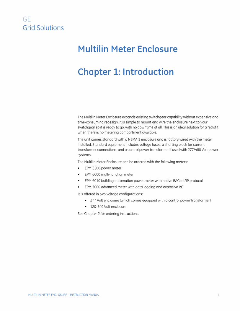
The Multilin Meter Enclosure expands existing switchgear capability without expensive and time-consuming redesign. It is simple to mount and wire the enclosure next to your switchgear so it is ready to go, with no downtime at all. This is an ideal solution for a retrofit when there is no metering compartment available.
The unit comes standard with a NEMA 1 enclosure and is factory wired with the meter installed. Standard equipment includes voltage fuses, a shorting block for current transformer connections, and a control power transformer if used with 277/480 Volt power systems.
The Multilin Meter Enclosure can be ordered with the following meters:
• EPM 2200 power meter
• EPM 6000 multi-function meter
• EPM 6010 building automation power meter with native BACnet/IP protocol
• EPM 7000 advanced meter with data logging and extensive I/O
It is offered in two voltage configurations:
• 277 Volt enclosure (which comes equipped with a control power transformer)
• 120-240 Volt enclosure
See Chapter 2 for ordering instructions.
MULTILIN METER ENCLOSURE – INSTRUCTION MANUAL 1
CHAPTER 1: INTRODUCTION
1.1 Product HandlingNote READ AND UNDERSTAND THE INSTRUCTONS CONTAINED IN THIS DOCUMENT BEFORE
ATTEMPTING TO UNPACK, INSTALL, OPERATE, OR MAINTAIN THIS EQUIPMENT.
Every effort is made to insure that the equipment arrives undamaged and ready to be installed. Packing is designed to protect internal components as well as the enclosure. Do not remove protective packing until you are ready to install the equipment.
When you receive the equipment, you should inspect the shipping container for any obvious signs of rough handling and/or external damage that occurred during transportation. Record any external and internal damage for reporting to the transportation carrier and GE Multilin. All claims should be as specific as possible and include general order numbers.
You will find a plastic bag of instruction booklets and/or CDs in the shipping container. Store these documents in a safe place.
2 MULTILIN METER ENCLOSURE – INSTRUCTION MANUAL
CHAPTER 1: INTRODUCTION
1.2 Safety PrecautionsNote All safety codes, safety standards, and/or regulations must be strictly observed in the
installation, operation, and maintenance of this device.
Hazardous voltages that can cause death or severe personal injury are present inside enclosure. Follow proper installation, operation, and maintenance procedures to avoid these voltages.
Completely read and understand the material presented in this document before attempting installation, operation, or application of the equipment. In addition, only qualified persons should be permitted to perform any work associated with the equipment. Any wiring instructions presented in this document must be followed precisely. Failure to do so could cause permanent equipment damage.
All possible contingencies that may arise during installation, operation, or maintenance, and all details and variations of this equipment do not purport to be covered by these instructions. If further information is desired by purchaser regarding a particular installation, operation, or maintenance of particular equipment, contact a GE Multilin (GE Grid Solutions) representative.
1.3 Storage
Although it has been well packaged, this equipment should not be stored outdoors. If the equipment is to be stored indoors for any period of time, it should be stored with its protective packaging in place. Refer to the EPM 2200, EPM 6000, EPM 6010, and EPM 7000 Instruction Manuals, on the enclosed CD, for the meter storage requirements.
1.4 Compliance
UL508A (Industrial control panel), UL/cUL Listed File number e358101.
MULTILIN METER ENCLOSURE – INSTRUCTION MANUAL 3
CHAPTER 1: INTRODUCTION
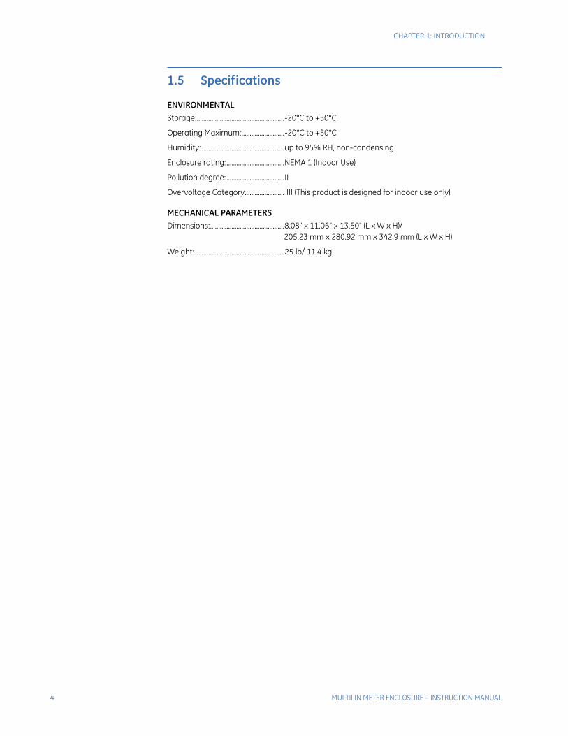
1.5 Specifications
ENVIRONMENTALStorage:.....................................................-20°C to +50°C
Operating Maximum:..........................-20°C to +50°C
Humidity: ..................................................up to 95% RH, non-condensing
Enclosure rating:...................................NEMA 1 (Indoor Use)
Pollution degree: ...................................II
Overvoltage Category........................ III (This product is designed for indoor use only)
MECHANICAL PARAMETERSDimensions:.............................................8.08" x 11.06" x 13.50" (L x W x H)/
205.23 mm x 280.92 mm x 342.9 mm (L x W x H)
Weight: ......................................................25 lb/ 11.4 kg
4 MULTILIN METER ENCLOSURE – INSTRUCTION MANUAL

Multilin Meter Enclosure
Chapter 2: Ordering Information
GE Grid Solutions
Ordering Information
2.1 Order Codes
The order codes for the EPM 2200, EPM 6000, EPM 6010, and EPM 7000 are indicated below.
Refer to the above EPM product manuals for full specifications.
* Software Options are only available with Communications Option S
Table 2–1: Order Codes for EPM 2200 with Meter Enclosure
PL2200 * – * – *Base Unit PL2200 | | | EPM 2200 Meter
Enclosure OptionENC120 | | NEMA1 Rated - Indoor, Single Meter Enclosure, 120V
ENC277 | | NEMA1 Rated - Indoor, Single Meter Enclosure, 277V
Software Option*
A1 | Volts and Amps Meter
B1 | Volts, Amps, Power and Frequency Meter
C1 | Volts, Amps, Power, Frequency and Energy Counters Meter
BN |BACnet Volts, Amps, Power, Frequency and Energy Counters Meter
Communications S RS485 Serial/KYZ Pulse
X None
B BACnet MS/TP Serial and Modbus TCP/IP Internet
MULTILIN METER ENCLOSURE – INSTRUCTION MANUAL 5
CHAPTER 2: ORDERING INFORMATION
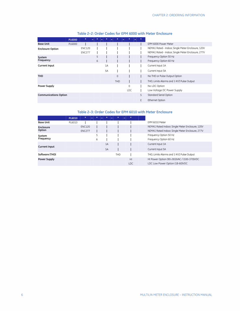
Table 2–2: Order Codes for EPM 6000 with Meter Enclosure
PL6000 * – * – * – * – * – *Base Unit PL6000 | | | | | | EPM 6000 Power Meter
Enclosure Option ENC120 | | | | | NEMA1 Rated - Indoor, Single Meter Enclosure, 120V
ENC277 | | | | | NEMA1 Rated - Indoor, Single Meter Enclosure, 277V
System Frequency
5 | | | | Frequency Option 50 Hz
6 | | | | Frequency Option 60 Hz
Current Input 1A | | | Current Input 1A
5A | | | Current Input 5A
THD 0 | | No THD or Pulse Output Option
THD | | THD, Limits Alarms and 1 KYZ Pulse Output
Power Supply 0 | No LDC Option
LDC | Low Voltage DC Power Supply
Communications Option S Standard Serial Option
E Ethernet Option
Table 2–3: Order Codes for EPM 6010 with Meter Enclosure
PL6010 * – * – * – * – *Base Unit PL6010 | | | | | EPM 6010 Meter
Enclosure Option
ENC120 | | | | NEMA1 Rated Indoor, Single Meter Enclosure, 120V
ENC277 | | | | NEMA1 Rated Indoor, Single Meter Enclosure, 277V
System Frequency
5 | | | Frequency Option 50 Hz
6 | | | Frequency Option 60 Hz
Current Input1A | | Current Input 1A
5A | | Current Input 5A
Software (THD) THD | THD, Limits Alarms and 1 KYZ Pulse Output
Power Supply HI HI Power Option (90-265)VAC / (100-370)VDC
LDC LDC Low Power Option (18-60)VDC
6 MULTILIN METER ENCLOSURE – INSTRUCTION MANUAL
CHAPTER 2: ORDERING INFORMATION
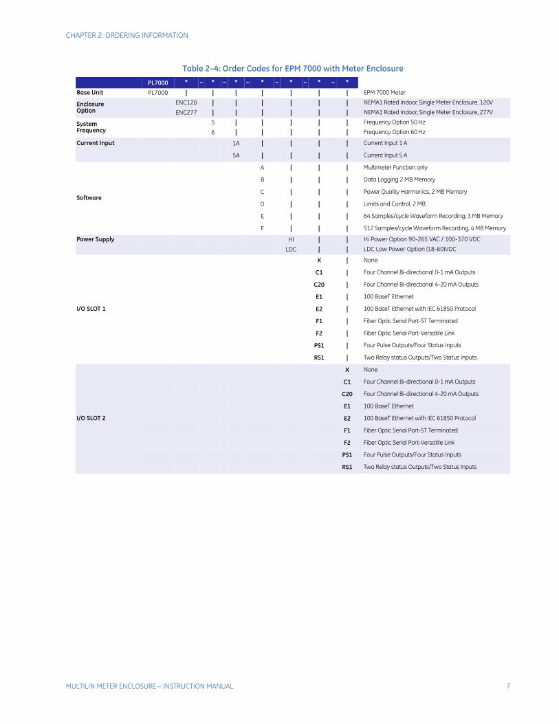
Table 2–4: Order Codes for EPM 7000 with Meter Enclosure
PL7000 * – * – * – * – * – * – *Base Unit PL7000 | | | | | | | EPM 7000 Meter
Enclosure Option
ENC120 | | | | | | NEMA1 Rated Indoor, Single Meter Enclosure, 120V
ENC277 | | | | | | NEMA1 Rated Indoor, Single Meter Enclosure, 277V
System Frequency
5 | | | | | Frequency Option 50 Hz
6 | | | | | Frequency Option 60 Hz
Current Input 1A | | | | Current Input 1 A
5A | | | | Current Input 5 A
Software
A | | | Multimeter Function only
B | | | Data Logging 2 MB Memory
C | | | Power Quality Harmonics, 2 MB Memory
D | | | Limits and Control, 2 MB
E | | | 64 Samples/cycle Waveform Recording, 3 MB Memory
F | | | 512 Samples/cycle Waveform Recording, 4 MB Memory
Power Supply HI | | Hi Power Option 90-265 VAC / 100-370 VDC
LDC | | LDC Low Power Option (18-60)VDC
I/O SLOT 1
X | None
C1 | Four Channel Bi-directional 0-1 mA Outputs
C20 | Four Channel Bi-directional 4-20 mA Outputs
E1 | 100 BaseT Ethernet
E2 | 100 BaseT Ethernet with IEC 61850 Protocol
F1 | Fiber Optic Serial Port-ST Terminated
F2 | Fiber Optic Serial Port-Versatile Link
PS1 | Four Pulse Outputs/Four Status Inputs
RS1 | Two Relay status Outputs/Two Status Inputs
I/O SLOT 2
X None
C1 Four Channel Bi-directional 0-1 mA Outputs
C20 Four Channel Bi-directional 4-20 mA Outputs
E1 100 BaseT Ethernet
E2 100 BaseT Ethernet with IEC 61850 Protocol
F1 Fiber Optic Serial Port-ST Terminated
F2 Fiber Optic Serial Port-Versatile Link
PS1 Four Pulse Outputs/Four Status Inputs
RS1 Two Relay status Outputs/Two Status Inputs
MULTILIN METER ENCLOSURE – INSTRUCTION MANUAL 7

CHAPTER 2: ORDERING INFORMATION
8 MULTILIN METER ENCLOSURE – INSTRUCTION MANUAL

Multilin Meter Enclosure
Chapter 3: Installation
GE Grid Solutions
Installation
Note All safety codes, safety standards, and/or regulations shall be strictly observed installation, operation, and maintenance of this device. This device shall be installed in an un-energized condition and as per the National Electric Code.
Choose a mounting location that offers a flat, rigid mounting surface capable of supporting the weight of the equipment. The unit weighs 25 lbs (11.4 kg) maximum. Mount the equipment in a suitable environment. These enclosures are designed for NEMA 1 environments and are manufactured of painted steel.
Check to make certain that there are no pipes, wires, or other mounting hazards in the immediate mounting area that could create a problem. Also make sure you have enough clearance around the enclosure to run wiring to it safely. GE Multilin recommends at least 2 feet of clearance around the enclosure.
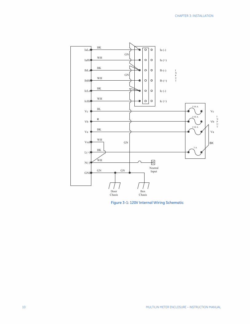
Carefully remove all packing material from the unit. Even though an equipment inspection was made when the equipment was received, make another careful inspection of the enclosure and the devices inside as packing material is removed. Be especially alert for distorted metal, loose wires, or damaged components. This is important because wiring can come loose in shipping and could cause a short circuit or voltage to be on the wrong terminal. Please inspect to make sure all the wiring is in the proper place. Refer to figures 3-1 and 3-2 for internal wiring schematics.
Note Extreme care shall be taken when mounting the enclosure, and making wire entry holes, to prevent metal chips, filings, and other contaminants from entering the enclosure which may damage the equipment and create a hazardous condition.
MULTILIN METER ENCLOSURE – INSTRUCTION MANUAL 9
CHAPTER 3: INSTALLATION
Figure 3-1: 120V Internal Wiring Schematic
10 MULTILIN METER ENCLOSURE – INSTRUCTION MANUAL

CHAPTER 3: INSTALLATION
Figure 3-2: 277V Internal Wiring Schematic
MULTILIN METER ENCLOSURE – INSTRUCTION MANUAL 11
CHAPTER 3: INSTALLATION
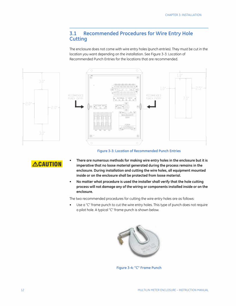
3.1 Recommended Procedures for Wire Entry Hole Cutting
The enclosure does not come with wire entry holes (punch entries). They must be cut in the location you want depending on the installation. See Figure 3-3: Location of Recommended Punch Entries for the locations that are recommended.
Figure 3-3: Location of Recommended Punch Entries
Note • There are numerous methods for making wire entry holes in the enclosure but it is imperative that no loose material generated during the process remains in the enclosure. During installation and cutting the wire holes, all equipment mounted inside or on the enclosure shall be protected from loose material.
• No matter what procedure is used the installer shall verify that the hole cutting process will not damage any of the wiring or components installed inside or on the enclosure.
The two recommended procedures for cutting the wire entry holes are as follows:
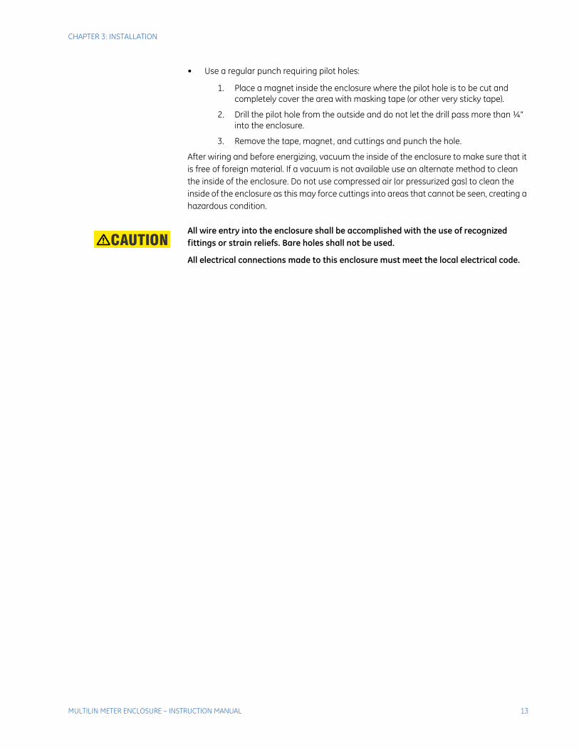
• Use a "C" frame punch to cut the wire entry holes. This type of punch does not require a pilot hole. A typical "C" frame punch is shown below.
Figure 3-4: "C" Frame Punch
12 MULTILIN METER ENCLOSURE – INSTRUCTION MANUAL
CHAPTER 3: INSTALLATION
• Use a regular punch requiring pilot holes:
1. Place a magnet inside the enclosure where the pilot hole is to be cut and completely cover the area with masking tape (or other very sticky tape).
2. Drill the pilot hole from the outside and do not let the drill pass more than ¼" into the enclosure.
3. Remove the tape, magnet, and cuttings and punch the hole.
After wiring and before energizing, vacuum the inside of the enclosure to make sure that it is free of foreign material. If a vacuum is not available use an alternate method to clean the inside of the enclosure. Do not use compressed air (or pressurized gas) to clean the inside of the enclosure as this may force cuttings into areas that cannot be seen, creating a hazardous condition.
Note All wire entry into the enclosure shall be accomplished with the use of recognized fittings or strain reliefs. Bare holes shall not be used.
All electrical connections made to this enclosure must meet the local electrical code.
MULTILIN METER ENCLOSURE – INSTRUCTION MANUAL 13

CHAPTER 3: INSTALLATION
3.2 Installation
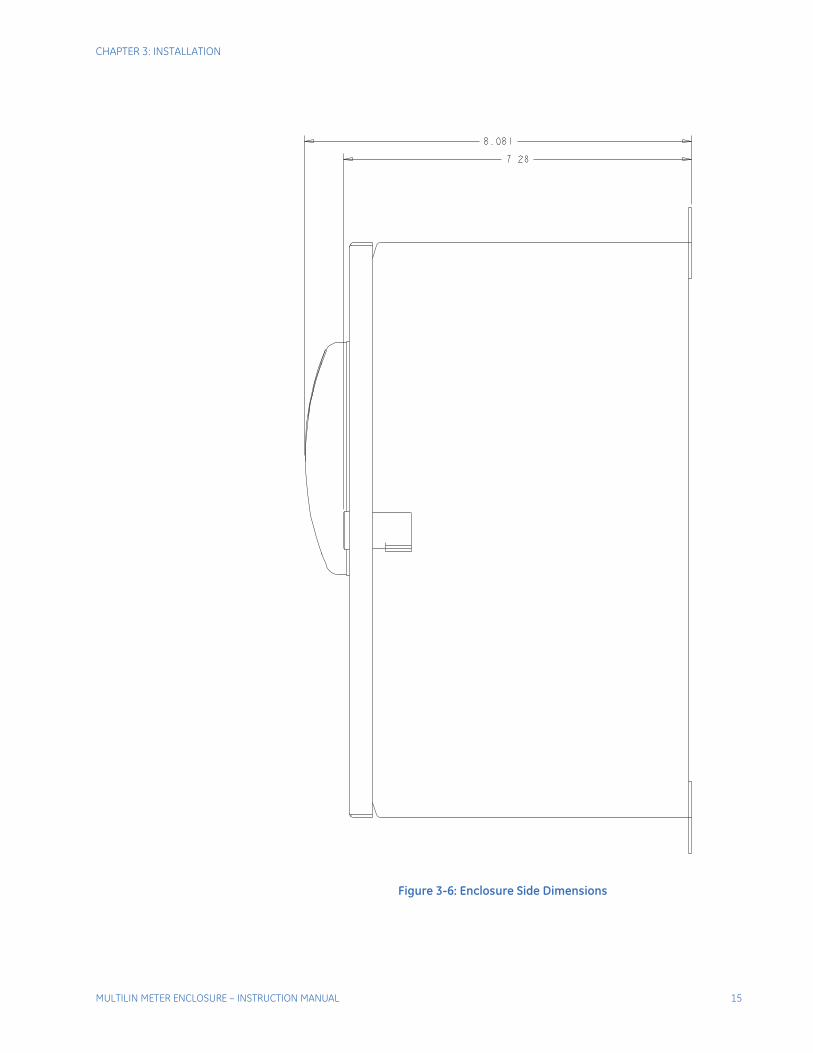
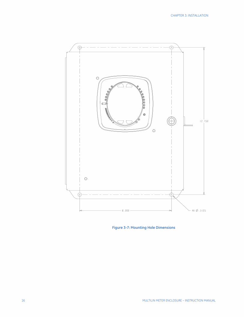
Refer to the following diagrams for enclosure and mounting dimensions.
Figure 3-5: Enclosure Front Dimensions
14 MULTILIN METER ENCLOSURE – INSTRUCTION MANUAL
CHAPTER 3: INSTALLATION
Figure 3-6: Enclosure Side Dimensions
MULTILIN METER ENCLOSURE – INSTRUCTION MANUAL 15
CHAPTER 3: INSTALLATION
Figure 3-7: Mounting Hole Dimensions
16 MULTILIN METER ENCLOSURE – INSTRUCTION MANUAL
CHAPTER 3: INSTALLATION
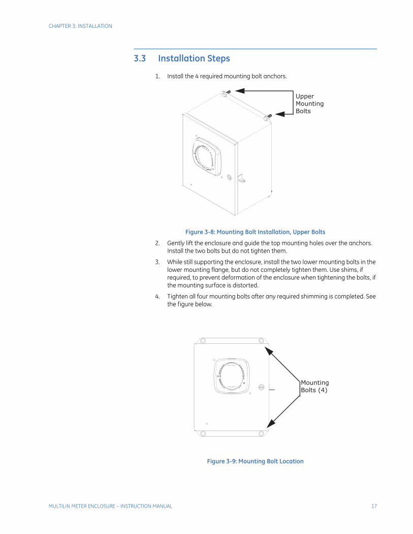
3.3 Installation Steps
1. Install the 4 required mounting bolt anchors.
Figure 3-8: Mounting Bolt Installation, Upper Bolts
2. Gently lift the enclosure and guide the top mounting holes over the anchors. Install the two bolts but do not tighten them.
3. While still supporting the enclosure, install the two lower mounting bolts in the lower mounting flange, but do not completely tighten them. Use shims, if required, to prevent deformation of the enclosure when tightening the bolts, if the mounting surface is distorted.
4. Tighten all four mounting bolts after any required shimming is completed. See the figure below.
Figure 3-9: Mounting Bolt Location
UpperMounting Bolts
Mounting Bolts (4)
MULTILIN METER ENCLOSURE – INSTRUCTION MANUAL 17

CHAPTER 3: INSTALLATION
3.4 Door Locking Instructions
The enclosure has been fitted with means for securing the door so it cannot be opened or tampered with. The padlock bracket can be secured in place with a padlock (3/8 inch shackle diameter). See the figure below.
Figure 3-10: Door with Lock
) g
18 MULTILIN METER ENCLOSURE – INSTRUCTION MANUAL
Multilin Meter Enclosure
Chapter 4: Electrical Wiring
GE Grid Solutions
Electrical Wiring
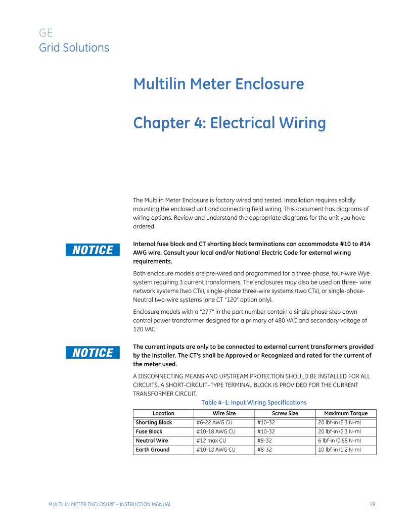
The Multilin Meter Enclosure is factory wired and tested. Installation requires solidly mounting the enclosed unit and connecting field wiring. This document has diagrams of wiring options. Review and understand the appropriate diagrams for the unit you have ordered.
NoteNOTE: Internal fuse block and CT shorting block terminations can accommodate #10 to #14 AWG wire. Consult your local and/or National Electric Code for external wiring requirements.
Both enclosure models are pre-wired and programmed for a three-phase, four-wire Wye system requiring 3 current transformers. The enclosures may also be used on three- wire network systems (two CTs), single-phase three-wire systems (two CTs), or single-phase-Neutral two-wire systems (one CT "120" option only).
Enclosure models with a "277" in the part number contain a single phase step down control power transformer designed for a primary of 480 VAC and secondary voltage of 120 VAC.
Note The current inputs are only to be connected to external current transformers provided by the installer. The CT's shall be Approved or Recognized and rated for the current of the meter used.
A DISCONNECTING MEANS AND UPSTREAM PROTECTION SHOULD BE INSTALLED FOR ALL CIRCUITS. A SHORT-CIRCUIT–TYPE TERMINAL BLOCK IS PROVIDED FOR THE CURRENT TRANSFORMER CIRCUIT.
Table 4–1: Input Wiring Specifications
Location Wire Size Screw Size Maximum Torque
Shorting Block #6-22 AWG CU #10-32 20 lbf-in (2.3 N-m)
Fuse Block #10-18 AWG CU #10-32 20 lbf-in (2.3 N-m)
Neutral Wire #12 max CU #8-32 6 lbf-in (0.68 N-m)
Earth Ground #10-12 AWG CU #8-32 10 lbf-in (1.2 N-m)
MULTILIN METER ENCLOSURE – INSTRUCTION MANUAL 19

CHAPTER 4: ELECTRICAL WIRING
4.1 Wiring InstructionsNoteWARNING! First connect Earth Ground as shown in the figure below.
Figure 4-1: Earth Ground Connection
Understand the diagram(s) that pertain to your unit before you begin the field wiring. The following figures show the available wiring options. Understand your system and use the appropriate figures.
NoteWARNING! CONTROL WIRING MAY HAVE VOLTAGE PRESENT THAT CAN CAUSE SEVERE PERSONAL INJURY OR DEATH. DE-ENERGIZE ALL CONDUCTORS BEFORE BEGINNING TO PERFORM ANY WIRING ACTIVITY WITHIN THE MULTILIN METER ENCLOSURE.
20 MULTILIN METER ENCLOSURE – INSTRUCTION MANUAL
CHAPTER 4: ELECTRICAL WIRING
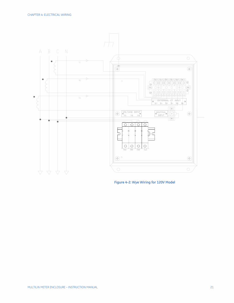
Figure 4-2: Wye Wiring for 120V Model
MULTILIN METER ENCLOSURE – INSTRUCTION MANUAL 21

CHAPTER 4: ELECTRICAL WIRING
Figure 4-3: Wye Wiring for 277V Model
22 MULTILIN METER ENCLOSURE – INSTRUCTION MANUAL
CHAPTER 4: ELECTRICAL WIRING
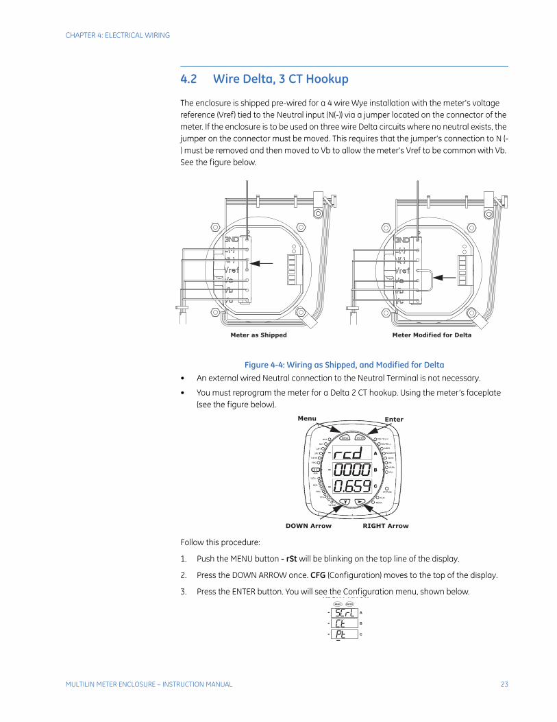
4.2 Wire Delta, 3 CT Hookup
The enclosure is shipped pre-wired for a 4 wire Wye installation with the meter's voltage reference (Vref) tied to the Neutral input (N(-)) via a jumper located on the connector of the meter. If the enclosure is to be used on three wire Delta circuits where no neutral exists, the jumper on the connector must be moved. This requires that the jumper's connection to N (-) must be removed and then moved to Vb to allow the meter's Vref to be common with Vb. See the figure below.
Figure 4-4: Wiring as Shipped, and Modified for Delta
• An external wired Neutral connection to the Neutral Terminal is not necessary.
• You must reprogram the meter for a Delta 2 CT hookup. Using the meter’s faceplate (see the figure below).
Follow this procedure:
1. Push the MENU button - rSt will be blinking on the top line of the display.
2. Press the DOWN ARROW once. CFG (Configuration) moves to the top of the display.
3. Press the ENTER button. You will see the Configuration menu, shown below.
Meter as Shipped Meter Modified for Delta
Menu Enter
DOWN Arrow RIGHT Arrow
RIGHT Arrow
A
B
C
-
-
-
MENU ENTER
MULTILIN METER ENCLOSURE – INSTRUCTION MANUAL 23
CHAPTER 4: ELECTRICAL WIRING
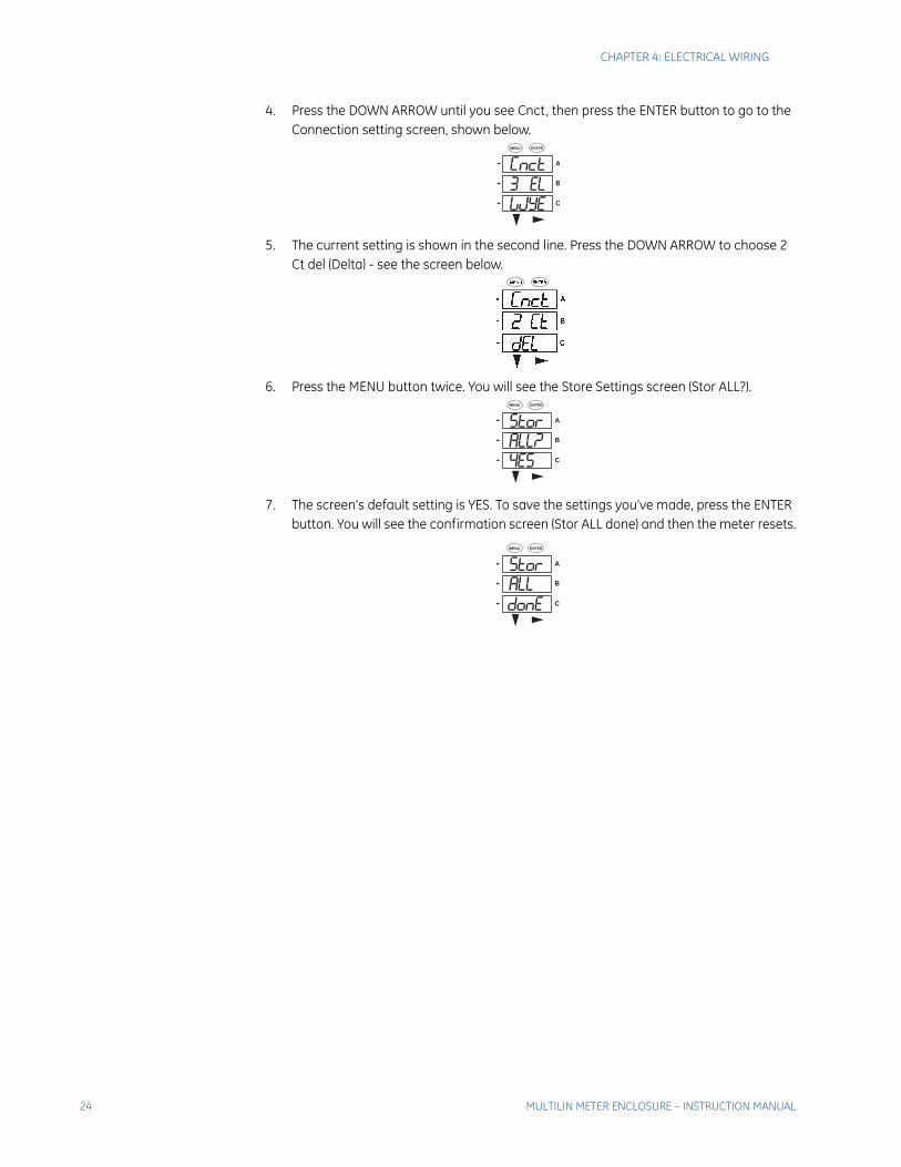
4. Press the DOWN ARROW until you see Cnct, then press the ENTER button to go to the Connection setting screen, shown below.
5. The current setting is shown in the second line. Press the DOWN ARROW to choose 2 Ct del (Delta) - see the screen below.
6. Press the MENU button twice. You will see the Store Settings screen (Stor ALL?).
7. The screen’s default setting is YES. To save the settings you’ve made, press the ENTER button. You will see the confirmation screen (Stor ALL done) and then the meter resets.
A
B
C
-
-
-
MENU ENTER
A
B
C
-
-
-
MENU ENTER
A
B
C
-
-
-
MENU ENTER
24 MULTILIN METER ENCLOSURE – INSTRUCTION MANUAL

Multilin Meter Enclosure
Chapter 5: Operation
GE Grid Solutions
Operation
5.1 Meter Enclosure operation
The meter enclosure with the 120 V option comes equipped with three 10mm x 38mm, 600V, 100mA, fast-acting fuses and one 10mm x 38mm, 500V, 3A, time delay fuse for the protection of the meter’s sense voltage and control power circuits, respectively.
The meter enclosure with 277 V option comes equipped with three 10mm x 38mm, 600V, 500mA, fast-acting fuses and one 10mm x 38mm, 500V, 3A, time delay fuse for the protection of the meter’s sense voltage and control power circuits, respectively.
A disconnecting means and upstream protection should be installed for all circuits. A short-circuit type terminal block is provided for the current transformer circuit. The terminal blocks for the current circuits are short-circuit type. Shorting screws are included (see instructions in Section 6.1).
The temperature rating for enclosure operation is from -20ºC to +50ºC.
For specific meter operating instructions, in the enclosure, refer to the respective EPM 2200, EPM 6000, EPM 6010, or EPM 7000 Instruction Manual on the enclosed CD.
MULTILIN METER ENCLOSURE – INSTRUCTION MANUAL 25

CHAPTER 5: OPERATION
26 MULTILIN METER ENCLOSURE – INSTRUCTION MANUAL
Multilin Meter Enclosure
Chapter 6: Maintenance
GE Grid Solutions
Maintenance
The Multilin Meter Enclosure is designed to be relatively maintenance-free under normal use. However, because of the variability of application conditions and the importance placed on dependable operation and inspection, you should perform maintenance checks on a regularly scheduled basis. Visually inspect for loose parts, wires, and/or hardware; inspect for discoloration of insulation and damaged or discolored components; be alert for accumulation of dirt and/or moisture on structure; check operation of disconnecting means and continuity of fuses, where applicable.
MULTILIN METER ENCLOSURE – INSTRUCTION MANUAL 27

CHAPTER 6: MAINTENANCE
6.1 Removing a Meter From Service
Follow these steps:
1. De-energize all circuits feeding the case.
2. If possible de-energize lines that the CTs are on.
3. Install 4 shorting screws, where shown, on the CT connection block - instructions follow.
NoteWARNING! If the meter must be removed from service, the secondary side of the current transformers MUST be short circuited to prevent a dangerous high voltage condition from appearing across the secondary wires of the current transformer. Arcing and damage to personnel and/or equipment can occur if the screws provided on the shorting block are not installed in the correct locations, prior to disconnecting any wires.
The four brass screws that are parked on each corner of the shorting block are used to short the three high (+) sides and one low (-) side of the CT outputs to the brass bar that is across the middle of the shorting block. The pre-installed jumper connects all lows together.
The brass screws need to be screwed down until the end of the screw makes contact with the terminal strip below, enabling the brass bar to become electrically common with the terminal strip.
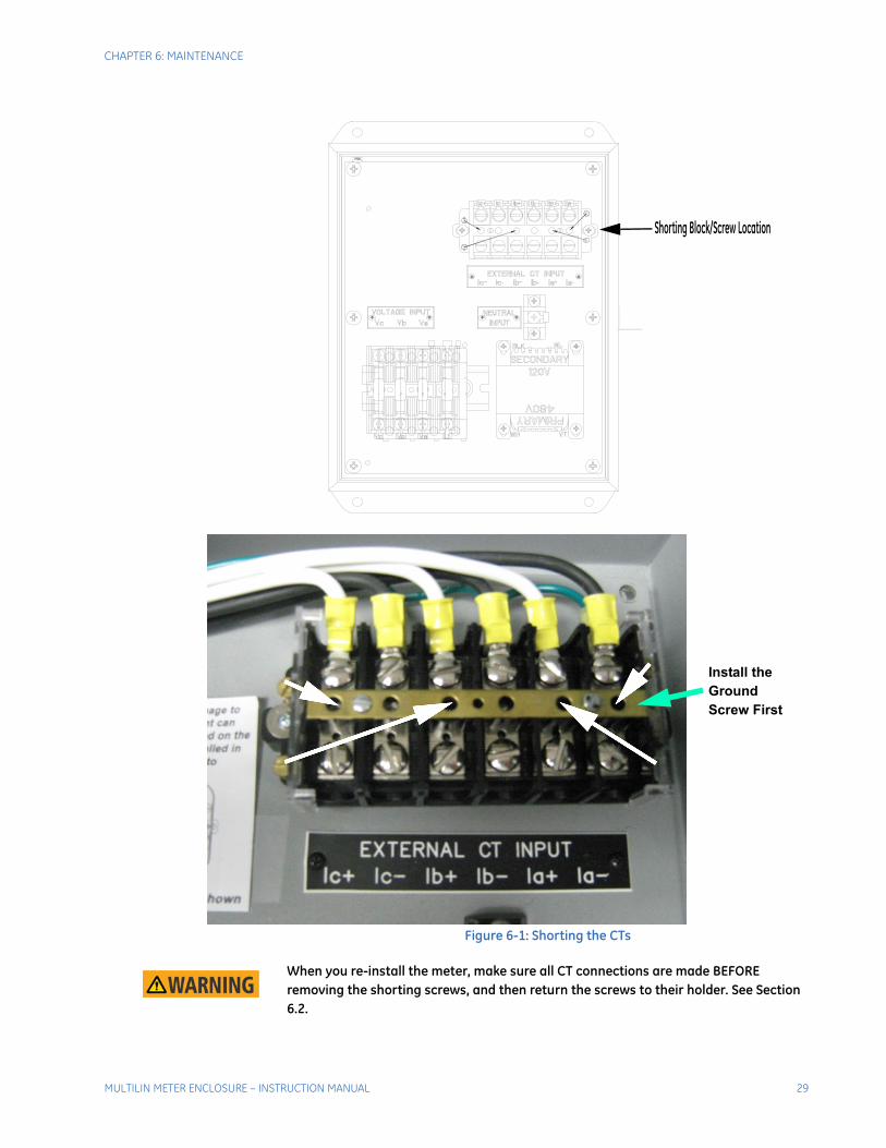
The figures below shows which terminals/holes the screws must be installed in to safely short the secondary of the CTs.
28 MULTILIN METER ENCLOSURE – INSTRUCTION MANUAL
CHAPTER 6: MAINTENANCE
Figure 6-1: Shorting the CTs
NoteWARNING! When you re-install the meter, make sure all CT connections are made BEFORE removing the shorting screws, and then return the screws to their holder. See Section 6.2.
Shorting Block/Screw Location
Install the Ground Screw First
MULTILIN METER ENCLOSURE – INSTRUCTION MANUAL 29

CHAPTER 6: MAINTENANCE
4. Remove the 4 fuses from the fuse holder.
5. Un-screw and disconnect the 6 current leads (CTs) from the meter.
6. Disconnect all connectors from the meter.
7. Remove the 4 mounting nuts.
8. Remove the meter.
6.2 Reinstalling the Meter
Follow this procedure to reinstall the meter:
1. Place meter in the cover cutout.
2. Tighten the 4 mounting nuts.
3. Insert all connectors into the appropriate sockets on the back of the meter.
4. Connect the 6 current leads (CTs) to the meter making sure they are attached in the proper order.
5. Install the 4 fuses in the fuse block, in their proper location.
6. Remove the 4 shorting screws from the CT connection block and return them to their storage positions. See the figure below.
Figure 6-2: Shorting Screws Returned to Their Storage Positions
7. Verify that no foreign material remains inside the enclosure, if there is clean it out.
8. Energize all circuits and verify operation.
Remove the Ground Screw Last
30 MULTILIN METER ENCLOSURE – INSTRUCTION MANUAL
Multilin Meter Enclosure
A: Appendix
GE Grid Solutions
Appendix
A.1 Change Notes
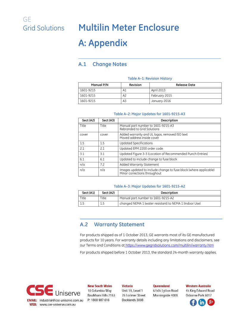
Table A–1: Revision History
Manual P/N Revision Release Date
1601-9215 A1 April 2013
1601-9215 A2 February 2015
1601-9215 A3 January 2016
Table A–2: Major Updates for 1601-9215-A3
Sect (A2) Sect (A3) Description
Title Title Manual part number to 1601-9215-A3Rebranded to Grid Solutions
cover cover Added warranty and UL logos, removed ISO textMoved address inside cover
1.5 1.5 Updated Specifications
2.1 2.1 Updated EPM 2200 order code
3.1 3.1 Updated Figure 3-3 (Location of Recommended Punch Entries)
6.1 6.1 Updated to include change to fuse block
n/a 7.2 Added Warranty Statement
n/a n/a Images updated to include change to fuse block (where applicable)Minor corrections throughout
Table A–3: Major Updates for 1601-9215-A2
Sect (A1) Sect (A2) Description
Title Title Manual part number to 1601-9215-A2
1.5 1.5 changed NEMA 1 (water resistant) to NEMA 1 (Indoor Use)
A.2 Warranty Statement
For products shipped as of 1 October 2013, GE warrants most of its GE manufactured products for 10 years. For warranty details including any limitations and disclaimers, see our Terms and Conditions at https://www.gegridsolutions.com/multilin/warranty.htm
For products shipped before 1 October 2013, the standard 24-month warranty applies.