Multilift RESIDENTAIL Planning Guide 000736 25-m08-2020
44
Multilift RESIDENTIAL VERTICAL PLATFORM LIFT PLANNING GUIDE Applicable Codes: ASME A17.1 ASME A18.1 Part No. 000736 25-m08-2020
Transcript of Multilift RESIDENTAIL Planning Guide 000736 25-m08-2020

MultiliftRESIDENTIAL
VERTICAL PLATFORM LIFT
PLANNING GUIDEApplicable Codes:
ASME A17.1ASME A18.1
Part No. 00073625-m08-2020

Copyright 2020Savaria Concord Lifts, Inc.All Rights ReservedPrinted in Canada

3
Purpose of this guideThis guide assists architects, contractors, and lift professionals to incorporate the Multilift Vertical Platform Lift into a residential or public building design. The design and manufacture of the Multilift Vertical Platform Lift meets the requirements of the following codes and standards:• ASME A18.1-2003 Section 5 (Private)• ASME A18.1-2005 Section 5 (Private)• ASME A18.1-2008 Section 5 (Private)• ASME A18.1-2011 Section 5 (Private)• ASME A18.1-2014 Section 5 (Private)• ASME A18.1-2017 Section 5 (Private)• ASME A17.1-1996 Section 21 (Private)We recommend that you contact your local authority having jurisdiction to ensure that you adhere to all local rules and regulations pertaining to vertical platform lifts.
IMPORTANT NOTICEThis Planning Guide provides nominal dimensions and specifications useful for the initial planning of a vertical platform lift project. Dimensions and specifications are subject to change without notice due to continually evolving code and product applications.
Before beginning actual construction, please consult Savaria or the authorized Savaria dealer in your area to ensure you receive your site-specific installation drawings with the dimensions and specifications for your project.
Visit our website (www.savaria.com) for the most recent Multilift drawings and dimensions.
How to use this guide1 Determine your client’s intended use of the lift.2 Determine the local code requirements.3 Determine the site installation parameters.4 Determine the cab type and hoistway size requirements.5 Plan for electrical requirements.
HistoryDecember 10, 2010 - Initial release of new formatJanuary 21, 2011 - Added Mobile Multilift drawing on pg. 24February 24, 2011 - Added information for automatic access ramp to “Features” in Specifications table on pg. 6June 1, 2011 - Updated all drawings to reflect current designOctober 18, 2012 - Added enclosure drawings - pg. 22 to 26; Added 3-gate drawing - pg 27October 25, 2012 - Added enclosure to cab types in specifications table on pg. 6; Revised list of drawings (removed 42” width) - pg. 13; Revised enclosure drawings (removed 42” width) - pg. 22 to 26April 25, 2013 - Correct power supply amperage from 20A to 15A in specifications table on pg. 6July 8, 2013 - Added Noise Level to specifications table on pg. 6December 5, 2013 - Added 42x48, 42x54 and 42x60 cab sizes to specifications table on pg. 6; added 42x48, 42x54 and 42x60 cab sizes to list of drawings on page 12 and a NOTE that the 42” wide cab sizes are not self-supporting and need wall mounting; added new drawings on pages 14, 16, 18, 20, 22, 24, 26 and 28December 17, 2013 - Added “must be a dedicated electrical line” to power supply specification in table on pg. 6March 13, 2014 - Revised “Features” in Specifications table on pg. 6November 5, 2014 - Revised Applicable Codes on pg. 3December 11, 2014 - Changed title to reflect RESIDENTIAL and revised codes on page 3January 20, 2015 - Added 2014 code in section aboveSeptember 24, 2015 - Added Daily Cycle to specifications table on page 6March 7, 2016 - Removed copyright from cover page; Savaria Corporation back to Savaria Concord Lifts, Inc.March 28, 2016 - Revised Power supply spec in table on page 6February 16, 2017 - Revised temperature spec in specs table on page 6February 26, 2018 - Removed pages 41 to 43September 27, 2018 - Added ASME 18.1-2017 to code list aboveJanuary 8, 2019 - Added spec for distance between 2 landings on page 6May 6, 2020 - Added Savaria Link option to specs table on page 6 and provisions by others on page 41January 15, 2020 - Added Load Calculations on page 11August 25, 2020 - Added mobile drawings on pages 40 and 41
Part No. 000736, 25-m08-2020 Multilift Residential Planning Guide

4
DescriptionThe Multilift Vertical Platform Lift is designed to provide easy access from one landing to another. The versatile design of this lift can be adapted to most architectural requirements and its rugged construction allows for outdoor or indoor use. It is an ideal deck lift for home use and is also approved for certain commercial accessibility projects as well. The Multilift, with its ACME screw drive system, provides safe and reliable operation.
Lift componentsThe Multilift consists of a tower and a platform as shown in Figure 1.
Figure 1: Typical lift, outdoor, unenclosed, no platform gate
Multilift Residential Planning Guide Part No. 000736, 25-m08-2020

5
Drive tower componentsThe Multilift drive tower components are shown in Figure 2.
Figure 2: Drive tower
Part No. 000736, 25-m08-2020 Multilift Residential Planning Guide

6
SpecificationsMultilift specifications
Applications Residential (indoor/outdoor); commercial (U.S.A.)
Load capacity 750 lb (340 kg)
Maximum travel distance 48” (1219 mm); optionally 72” (1829 mm)
Levels serviced 2
Distance between 2 landings 8” (203 mm) minimum
Travel speed 8 ft/min (0.04 m/s)
Temperature -20 °F to +122 °F (-29 °C to +50 °C)
Noise level (for typical installation) 65.9 dBA (up direction); 65.0 dBA (down direction) Measured at a height of 1m, distance of 1m, in front of the motor with all panels on
Daily cycle Normal: 10; Heavy: 25; Excessive: 40Maximum starts in 1 hour on standard installation: 10NOTE: Please consult your Sales Representative if there a chance you may exceed these amounts.
Cab types/sizes
Type 2 (enclosed and unenclosed hoistway):• 34” x 48” (863 mm x 1219 mm)• 34” x 54” (863 mm x 1371 mm)• 34” x 60” (863 mm x 1524 mm)Type 3/4: (enclosed and unenclosed hoistway):• 35” x 47” (889 mm x 1194 mm)• 35” x 53” (889 mm x 1346 mm)• 35” x 59” (889 mm x 1499 mm)Type 2 with platform gate (unenclosed hoistway):• 36” x 48” (914 mm x 1219 mm)• 36” x 54” (914 mm x 1371 mm)• 36” x 60” (914 mm x 1524 mm)Type 3/4 with platform gate (unenclosed hoistway):• 36” x 47” (914 mm x 1194 mm)• 36” x 53” (914 mm x 1346 mm)• 36” x 59” (914 mm x 1499 mm)All enclosure -Type 2, Type 3, Type 3 with 45” opening, Type 4, Type 4 with 45” opening• 36” x 48” (914 mm x 1219 mm)• 36” x 54” (914 mm x 1371 mm)• 36” x 60” (914 mm x 1524 mm)Type 2, 3, or 4 (with/without platform gate and with enclosure)• 42” x 48” (1067 mm x 1219 mm)• 42” x 54” (1067 mm x 1371 mm)• 42” x 60” (1067 mm x 1524 mm)NOTE that the 42” wide cab units are not self-supporting and need wall mounting.
Side guard panels 42 1/8” (1070 mm) side guard panels on platform
Cab accessFront/rear access - standard (platform Type 2)90 degree access - optional (platform Type 3 and 4)
Power supply 120 VAC, 20 A, 60 Hz, single phase (must be a dedicated electrical line)
Drive systemAcme screw and back-up nut1 hp (0.75 Kw) motor, 110 VACOptional 1 hp, 24-volt battery model available
Control system Electronic-free relay logic controller
Finish Beige electrostatic powder coat paint on all steel surfaces and vacuum-formed plastics
Features
Call/send stations at landingsContinuous-pressure type buttonsOperating control buttons on platformEmergency manual lowering/raising deviceLow-voltage controlsUnderpan sensorsNon-skid platform surfaceAutomatic access ramp (16”); field reversible to suit installation needsEmergency stop button
Options Savaria Link remote monitoring
Multilift Residential Planning Guide Part No. 000736, 25-m08-2020

7
Site construction detailsThe self-supporting base must be able to support at least 3000 lb (13.3 kN) per Figure 3 and must be anchored to a concrete slab (or floor) per Figure 4. Make sure the slab (floor) surface is level.
Figure 3: Floor loading diagram
Figure 4: Anchor points
Part No. 000736, 25-m08-2020 Multilift Residential Planning Guide

8
Figure 5 illustrates the site construction details for a typical outdoor application.
Figure 5: Sample unenclosed outdoor application
⅛
Outdoor applications need a strong and stable surface that will not move throughout the years. For this reason, it is essential, when the temperature can get below the freezing point, to insert an insulate sheet between the concrete slab and the compaction rock. Figure 6 illustrates the concrete slab detail for a typical outdoor application.
Figure 6: Concrete slab detail
Multilift Residential Planning Guide Part No. 000736, 25-m08-2020

9
Landing gate/door detailsLanding gate/door details are specific to each job site. Be sure to refer to your site-specific installation drawings.
There are two options that can be used when preparing for installation of the gate (or door with sill angle). Figure 7 illustrates the two options for a gate. Refer to the Installation Guide for details on installing the landing gate or door.
• Option 1 – Notch out the landing so that the gate angle bracket (or door sill angle) is flush with the vertical landing surface.
• Option 2 – Install a 1/4” fascia panel to fill in the gap in the vertical landing surface from underneath the gate angle bracket (or door sill angle) down to the floor/ground. If your site has a hoistway or pit, be sure to add 1/4” to those dimensions to account for the 1/4” fascia panel.
Figure 7: Options used when installing a gate
Notch out landing to install gate Install fascia panel for gate
Part No. 000736, 25-m08-2020 Multilift Residential Planning Guide

10
Commercial requirementsFollowing are the requirements for commercial applications.
ASME A17.1: An enclosure or hoistway is required (see Figure 8 below).
Figure 8: Hoistway requirements
ASME A17.1/A18.1: The items listed below are required.
• Grab bar (hand rail)• Emergency light on platform• Controller redundancy• Emergency stop/alarm• Platform gate or hoistway• Top landing gate• Disconnect (provided by others)• Door locks
CSA: The Multilift is not approved for commercial use in Canada.
Multilift Residential Planning Guide Part No. 000736, 25-m08-2020

11
Load calculations
Lift Model(inches)
MAX Tower WeightT (lbs)
-MAX Car Weight
CAR (lbs)
MAX CapacityCAP (lbs)
n/a n/a Pit LoadP (lbs)
EstimatedImpact Load
R3 (lbs)
48 500 400 750 N/A N/A 1650 300060 650 400 750 N/A N/A 1800 300072 650 400 750 N/A N/A 1800 3000
N.B.Calculations do not include forces due to wind, seismic loading, any environmental loading and forces due to acceleration.Calculations are assuming that the unit is self supported.A minimum Safety Factor of 4 is recommended; check local code requirements or building special requirements.The average standard cab weight is 350 lbs; the values vary accordingly. If the building doesn't allow bracket mounting spacing of 36", R2 needs to be increased accordingly.The Impact Load is not "necessary" if the lift is installed properly and maintained according to the manufacturer's recommendationIf the unit is ordered with base legs, the Pit Load related to cab weight and capacity will be spread on the footprint.
Lift Model(inches)
MAX Tower WeightT (lbs)
MAX Enclosure
WeightT (lbs)
MAX Car Weight
CAR (lbs)
MAX CapacityCAP (lbs)
Anchor on the wall for tall
travel
MAX Wall Support Loads per
mounting points (double the values = per bracket)
R2 (lbs)
Pit Load
P (lbs)
EstimatedImpact Load
R3 (lbs)
48 500 625 400 750 2275 300060 650 675 400 750 102 472 2475 300072 650 725 400 750 102 472 2525 3000
36x60" Platform, Screw Drive, Hoistway Application No Safety Factor
SAVARIA Multilift
No Safety FactorVertical Platform Lift Anchoring Loads (worst case scenario)
36x60" Platform, Screw Drive, Hoistway Application
Vertical Platform Lift Anchoring Loads (worst case scenario)
Part No. 000736, 25-m08-2020 Multilift Residential Planning Guide

12
Cab typesType 2 cab (standard)
For type 2 cabs, entry and exit are available from both ends of the platform.
Figure 9: Type 2
Type 2LplatformTo
wer
Entrance
Type 2Rplatform
Entrance
Exit Exit
Tow
er
Type 3 and 4 cab (optional)For type 3 and 4 cabs, entry and exit are available from one end and one side of the platform.
Figure 10: Type 3 and 4
Type 4platform
Entrance
Tow
erType 3platform To
wer
Entrance
Exit Exit
Multilift Residential Planning Guide Part No. 000736, 25-m08-2020

13
DrawingsThe next several pages provide various Multilift drawings. Always refer to your installation drawings for details specific to your site.
• Elevation and plan view drawings (for the different cab types and sizes)
•Type 2, enclosed hoistway, 34'' x 48'', 34” x 54”, 34” x 60”•Type 3, enclosed hoistway, 35'' x 47'', 35” x 53”, 35” x 59”•Type 4, enclosed hoistway, 35'' x 47'', 35” x 53”, 35” x 59”
•Type 2, unenclosed hoistway, 34'' x 48'', 34” x 54”, 34” x 60”•Type 3, unenclosed hoistway, 35'' x 47'', 35” x 53”, 35” x 59”•Type 4, unenclosed hoistway, 35'' x 47'', 35” x 53”, 35” x 59”
•Type 2 with platform gate, unenclosed hoistway, 36'' x 48'', 36” x 54”, 36” x 60”•Type 3 with platform gate, unenclosed hoistway, 36'' x 47'', 36” x 53”, 36” x 59”•Type 4 with platform gate, unenclosed hoistway, 36'' x 47'', 36” x 53”, 36” x 59”
•Type 2 without platform gate – 42” x 48”, 42” x 54”, 42” x 60”•Type 3 without platform gate – 42” x 48”, 42” x 54”, 42” x 60”•Type 4 without platform gate – 42” x 48”, 42” x 54”, 42” x 60”•Type 2 with platform gate – 42” x 54”, 42” x 60”•Type 3 (42” B side opening) with platform gate – 42” x 60”•Type 4 with platform gate – 42” x 54”, 42” x 60”•Type 2, enclosure, 36” x 48'', 36” x 54”, 36” x 60”•Type 3, enclosure, 36” x 48'', 36” x 54”, 36” x 60”•Type 3 (45” opening), enclosure, 36” x 48'', 36” x 54”, 36” x 60”•Type 4, enclosure, 36” x 48'', 36” x 54”, 36” x 60”•Type 4 (45” opening), enclosure, 36” x 48'', 36” x 54”, 36” x 60”
•Type 2, enclosure, 42” x 48'', 42” x 54”, 42” x 60”•Type 3, enclosure, 42” x 48'', 42” x 54”, 42” x 60”•Type 4, enclosure, 42” x 48'', 42” x 54”, 42” x 60”•Type 2, three gates, 36” x 48'', 36” x 54”, 36” x 60”
• Two sample landing gate layout drawings are provided
•42” x 36” auto left-hand gate•42” x 36” manual left-hand gate
• Mobile Multilift drawings
Note: For specifications on other landing gates and doors, go to our website www.savaria.com, select the “architects and builders” tab at the top of the page and then select “Doors and Gates” from the menu on the left-hand side of the page.
The link is as follows: http://www.savaria.com/architects/drawings/doors-gates/index.php.
Part No. 000736, 25-m08-2020 Multilift Residential Planning Guide

14
Figure 11: Elevation and plan view - type 2, enclosed hoistway, 34” cab
Multilift Residential Planning Guide Part No. 000736, 25-m08-2020
15
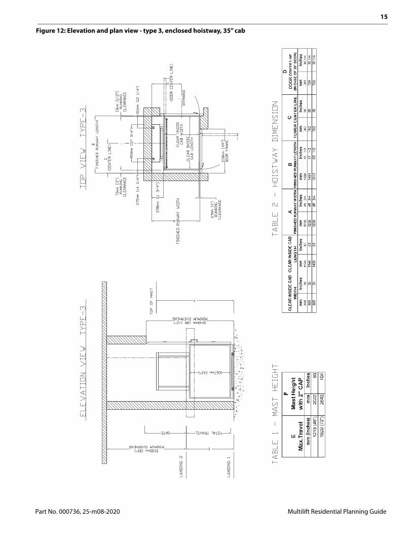
Figure 12: Elevation and plan view - type 3, enclosed hoistway, 35” cab
Part No. 000736, 25-m08-2020 Multilift Residential Planning Guide

16
Figure 13: Elevation and plan view - type 4, enclosed hoistway, 35” cab
Multilift Residential Planning Guide Part No. 000736, 25-m08-2020

17
Figure 14: Elevation and plan view - type 2, unenclosed hoistway, 34” cab
mm
Inch
esm
mIn
ches
mm
Inch
esm
mIn
ches
mm
Inch
esm
mIn
ches
864
3412
1948
1314
51
3/4
622
24
1/2
756
29
3/4
864
3413
7254
1314
51
3/4
699
27
1/2
756
29
3/4
864
3415
2460
1314
51
3/4
775
30
1/2
756
29
3/4
N/A
CLE
AR IN
SID
E C
ABW
IDTH
CLE
AR IN
SID
E C
ABLE
NG
TH
DD
OO
R C
ENTE
R LI
NE(IN
CAS
E O
F 36
" DO
OR)
AFI
NISH
ED R
UNW
AY W
IDTH
BFI
NISH
ED R
UNW
AY L
ENG
THC
TOW
ER C
ENTE
R L
INE
EM
ax.T
rave
lm
m (I
nche
s)
mm
Inch
es12
19 (4
8")
2032
8018
29 (7
2")
2642
104
FM
ast H
eigh
tw
ith 2
" C
AP
Part No. 000736, 25-m08-2020 Multilift Residential Planning Guide

18
Figure 15: Elevation and plan view - type 3, unenclosed hoistway, 35” cab
Multilift Residential Planning Guide Part No. 000736, 25-m08-2020

19
Figure 16: Elevation and plan view - type 4, unenclosed hoistway, 35” cab
Part No. 000736, 25-m08-2020 Multilift Residential Planning Guide

20
Figure 17: Elevation and plan view - type 2 with platform gate, unenclosed hoistway, 36” cab
Multilift Residential Planning Guide Part No. 000736, 25-m08-2020

21
Figure 18: Elevation and plan view - type 3 with platform gate, unenclosed hoistway, 36” cab
Part No. 000736, 25-m08-2020 Multilift Residential Planning Guide

22
Figure 19: Elevation and plan view - type 4 with platform gate, unenclosed hoistway, 36” cab
Multilift Residential Planning Guide Part No. 000736, 25-m08-2020

23
Figure 20: Elevation and plan view – type 2 without platform gate, 42” cab
Part No. 000736, 25-m08-2020 Multilift Residential Planning Guide

24
Figure 21: Elevation and plan view – type 3 without platform gate, 42” cab
Multilift Residential Planning Guide Part No. 000736, 25-m08-2020

25
Figure 22: Elevation and plan view – type 4 without platform gate, 42” cab
Part No. 000736, 25-m08-2020 Multilift Residential Planning Guide

26
Figure 23: Elevation and plan view – type 2 with platform gate, 42” cab
Multilift Residential Planning Guide Part No. 000736, 25-m08-2020

27
Figure 24: Elevation and plan view – type 3 (42” B side opening) with platform gate, 42” cab
Part No. 000736, 25-m08-2020 Multilift Residential Planning Guide

28
Figure 25: Elevation and plan view – type 4 with platform gate, 42” cab
Multilift Residential Planning Guide Part No. 000736, 25-m08-2020

29
Figure 26: Elevation and plan view - type 2, enclosure, 36” cab
Part No. 000736, 25-m08-2020 Multilift Residential Planning Guide

30
Figure 27: Elevation and plan view - type 3, enclosure, 36” cab
Multilift Residential Planning Guide Part No. 000736, 25-m08-2020

31
Figure 28: Elevation and plan view - type 3 (45” opening), enclosure, 36” cab
Part No. 000736, 25-m08-2020 Multilift Residential Planning Guide

32
Figure 29: Elevation and plan view - type 4, enclosure, 36” cab
Multilift Residential Planning Guide Part No. 000736, 25-m08-2020

33
Figure 30: Elevation and plan view - type 4 (45” opening), enclosure, 36” cab
Part No. 000736, 25-m08-2020 Multilift Residential Planning Guide

34
Figure 31: Elevation and plan view – type 2 enclosure, 42” cab
Multilift Residential Planning Guide Part No. 000736, 25-m08-2020

35
Figure 32: Elevation and plan view – type 3 enclosure, 42” cab
Part No. 000736, 25-m08-2020 Multilift Residential Planning Guide

36
Figure 33: Elevation and plan view – type 4 enclosure, 42” cab
Multilift Residential Planning Guide Part No. 000736, 25-m08-2020

37
Figure 34: Elevation and plan view - type 2, three gates
Part No. 000736, 25-m08-2020 Multilift Residential Planning Guide

38
Figure 35: 42” x 36” Auto left-hand gate
Multilift Residential Planning Guide Part No. 000736, 25-m08-2020

39
Figure 36: 42” x 36” Manual left-hand gate
Part No. 000736, 25-m08-2020 Multilift Residential Planning Guide

40
Figure 37: Mobile Multilift RH
Multilift Residential Planning Guide Part No. 000736, 25-m08-2020

41
Figure 38: Mobile Multilift LH
Part No. 000736, 25-m08-2020 Multilift Residential Planning Guide

42
Provisions by others
Multilift Residential Planning Guide Part No. 000736, 25-m08-2020

43
Provisions by others - Savaria Link optionIf you have the Savaria Link Ethernet remote monitoring option, ensure that you have an Ethernet connection with Internet capability in the vicinity of the unit’s controller.If you have the Savaria Link Wireless remote monitoring option, ensure that you have a wireless signal with Internet capability in the vicinity of the unit’s controller.
Multilift Residential Planning Guide25-m08-2020

Multilift RESIDENTIALVertical Platform LiftPLANNING GUIDEPart No. 000736Copyright 2020
Savaria Concord Lifts, Inc.www.savaria.com
Sales2 Walker DriveBrampton, Ontario L6T 5E1CanadaTel: (905) 791-5555Fax: (905) 791-2222Toll Free: 1-800-661-5112