MULTIFUNCTION CONTROL PANEL REPLACEMENT IN B737
12
737424-HDK02 i Issue: 4 Date: 01/04/20 MULTIFUNCTION CONTROL PANEL REPLACEMENT IN B737 TITULO/TITLE: MAINTENANCE MANUAL SUPPLEMENT DOCUMENT NR.: 737424-HDK02 EDIC./ISS. 1 2 3 4 FECHA/DT. 14/01/20 10/02/20 18/03/20 01/04/20 NOMBRE/NAME FIRMA/SIGNAT. FECHA/DT. PREPARED F. GUERRERO 01/04/20 REVISED A. SÁNCHEZ 01/04/20 APPROVED (CVE) A. SÁNCHEZ 01/04/20
Transcript of MULTIFUNCTION CONTROL PANEL REPLACEMENT IN B737

737424-HDK02 i Issue: 4 Date: 01/04/20
MULTIFUNCTION CONTROL PANEL
REPLACEMENT IN B737
TITULO/TITLE:
MAINTENANCE MANUAL SUPPLEMENT
DOCUMENT NR.: 737424-HDK02
EDIC./ISS. 1 2 3 4
FECHA/DT. 14/01/20 10/02/20 18/03/20 01/04/20
NOMBRE/NAME FIRMA/SIGNAT. FECHA/DT.
PREPARED F. GUERRERO 01/04/20
REVISED
A. SÁNCHEZ 01/04/20
APPROVED (CVE)
A. SÁNCHEZ 01/04/20
737424-HDK02 ii Issue: 4 Date: 01/04/20
S4A S.A. posee los derechos de autor de este documento que se entrega confidencialmente, y que no será utilizado con ningún fin distinto de aquel para el que ha sido entregado, no siendo tampoco reproducido en su totalidad o en parte, copiado o transmitido a ninguna persona sin autorización del propietario o del solicitante del trabajo.
S4A copyrights this document, which is delivered in confidence. This document will not be used for any other different purpose than that to which it is intended. This document can not be reproduced by any means without the written authorization of S4A.
Cualquier persona no autorizada que obtenga posesión de este documento por cualquier razón, deberá enviarlo junto con su nombre y dirección, en sobre sellado a:
Any not authorized person obtaining this document, for whichever reason, has to send it along with his/her name and address to: S4A Solutions for Aviation C/ Corazón de María 48 B 28002 Madrid (España)
Los gastos de correo serán reembolsados.
Mail expenses will be reimbursed
LISTA DE DISTRIBUCIÓN/DISTRIBUTION LIST
NAME COMPANY NR. COPIES
INTERNAL: ARCHIVO S4A 1
AWARE: CALIDAD S4A -
EXTERNAL: LOGIC AIR 1
737424-HDK02 iii Issue: 4 Date: 01/04/20
REGISTRO DE EDICIONES DE PAGINAS/PAGE ISSUE REGISTRATION
PAGINA/PAGE EDICION/ISSUE
PAGINA/PAGE EDICION/ISSUE
PAGINA/PAGE EDICION/ISSUE
i to iii
1 to 8
4 4
REGISTRO DE CAMBIOS EN EL DOCUMENTO/DOCUMENT CHANGE REGISTRATION
EDIC./REV. FECHA/DATE RAZON DEL CAMBIO/CHANGE REASON
1
2
3
4
14/01/20
10/02/20
18/03/20
01/04/20
EDICIÓN ORIGINAL/ORIGINAL ISSUE CUSTOMER REQUEST (MAJOR MODIFICATION) EASA COMMENTS (MAJOR MODIFICATION) CUSTOMER REQUEST (MINOR MODIFICATION)
737424-HDK02 1 Issue: 4 Date: 01/04/20
TABLE OF CONTENTS
1. OBJECT............................................................................................................................. 2 2. NORMATIVE COMPLIANCE .............................................................................................. 2 3. APPLICABILITY ................................................................................................................. 2 4. APPROVAL........................................................................................................................ 2 5. INSTALLATION DESCRIPTION.......................................................................................... 2 6. SERVICE CENTER ............................................................................................................ 4 7. MAINTENANCE PROGRAM ............................................................................................... 4 8. MAINTENANCE SCHEDULE AND METHODS. ................................................................... 6
8.1. CONTROL PANEL DISPLAY ...................................................................................6 8.2. ELECTRICAL WIRING ..............................................................................................6
9. SPECIAL PROCEDURES ................................................................................................... 7 9.1. ELECTRICAL WIRING DAMAGES ..........................................................................7
10. ACCEPTABLE CORROSION LEVELS .............................................................................. 8 11. AIRWORTHINESS LIMITATIONS ..................................................................................... 8 12. EWIS INSTRUCTIONS ..................................................................................................... 8 13. INSTALLATION/ REMOVAL INSTRUCTIONS ................................................................... 8
13.1. Removal instructions ...............................................................................................8 13.2. Installation instructions ............................................................................................9
S4A
737424-HDK02 Issue: 4 Date: 01/04/20
2
1. OBJECT
The purpose of this document is to describe the actions to be followed in order to ensure continued airworthiness of Boeing 737 aircraft where S4A Service Bulletin
737424-SB001 has been implemented. The stated service bulletin consists on the multifunction control panel
replacement on board Boeing 737 aircraft.
2. NORMATIVE COMPLIANCE
This document shows compliance with next paragraphs of normative CS 25
Amendment 24: 25.1309 a) b) c) e)
25.1529
3. APPLICABILITY
This document is applicable to Boeing 737 aircraft where S4A Service Bulletin 737424-SB001 has been implemented.
4. APPROVAL
The technical content of this document is approved under the authority of DOA nr. EASA21.J.409
5. INSTALLATION DESCRIPTION
The Boeing 737 aircraft was modified installing a SBAS system as per EASA STC number 10043626. The operator has decided to replace the existing control panels (P/N CMA-5025) with a new single control panel Gable (P/N G7321-122). The rest of
the elements of the SBAS system are the same as before the modification. IMPORTANT NOTE: Neither the activation nor the operation of any
equipment is covered by this modification (equipment and connections are only installed as provisions; activation and operation shall be approved separately).
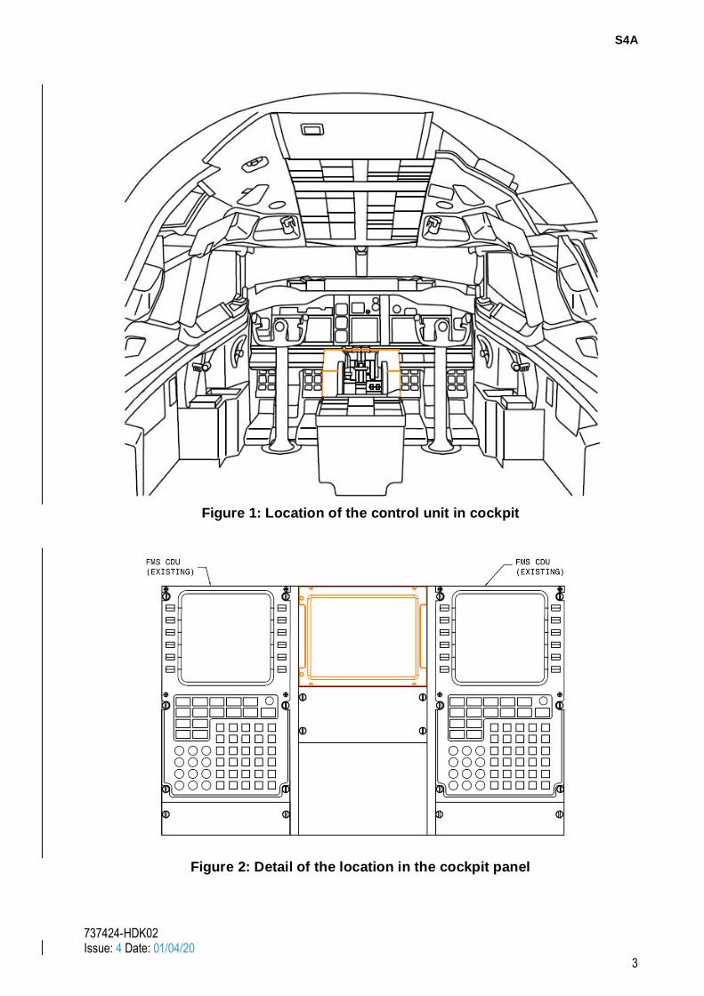
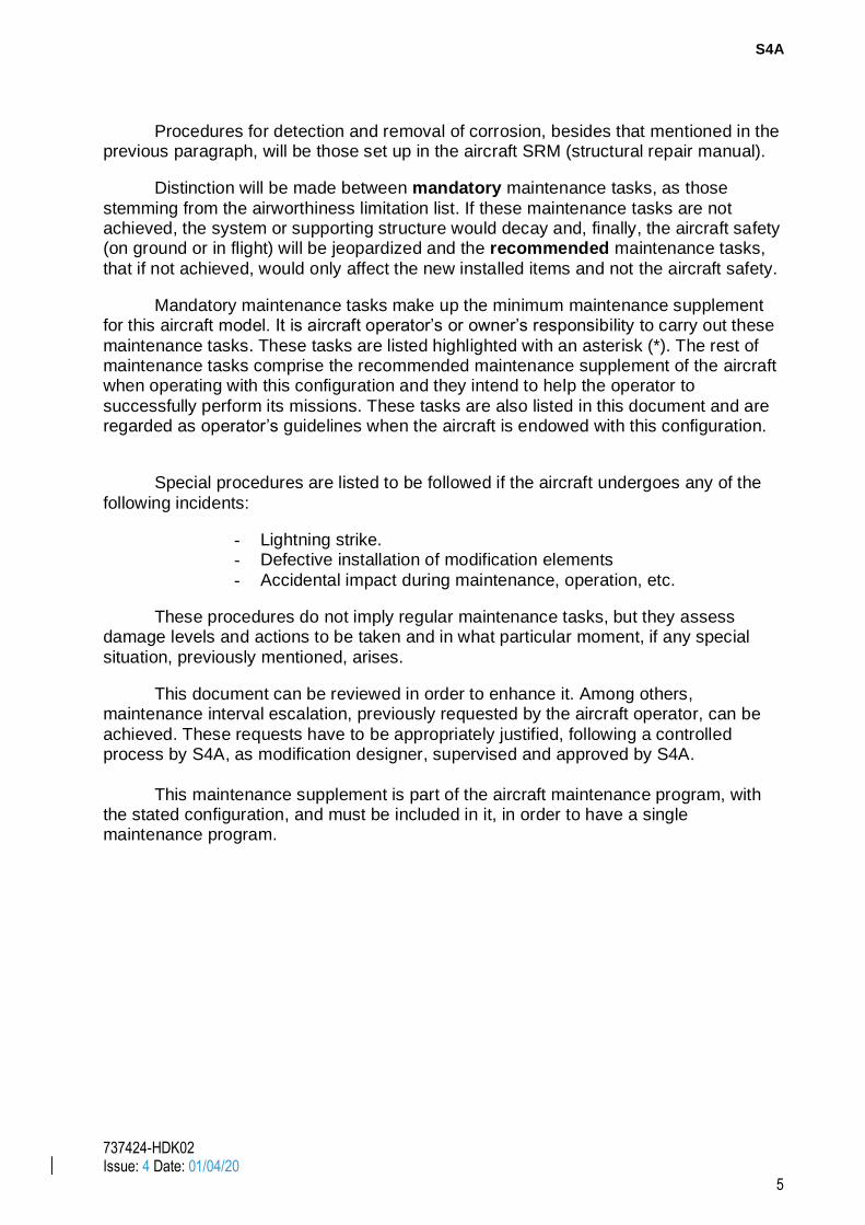
The new display is attached to the Forward Center Pedestal in the location indicated in next figures by means of standard fasteners.
S4A
737424-HDK02 Issue: 4 Date: 01/04/20
3
Figure 1: Location of the control unit in cockpit
Figure 2: Detail of the location in the cockpit panel

S4A
737424-HDK02 Issue: 4 Date: 01/04/20
4
6. SERVICE CENTER
The service center of the equipments comprising this system is:
Gables Engineering Inc. 247 Greco Avenue, Coral Gables, Florida 33146
Tel: (305) 774-4400
Fax: (305) 774-4465 www.gableseng.com
Corporation Logic Air Inc. 91 Gaston Dumoulin
Blainville (Québec) J7C 6B4
CANADA Tel: 579-637-3077
7. MAINTENANCE PROGRAM
It is clearly distinguished between maintenance actions on the new installed items and on the aircraft structure supporting them.
Another paragraph is included describing actions to be taken and procedures to
be followed in the event the aircraft undergoes any damage due to: lightning strike, ground vehicle impact, defective installation of new items, impacts due to maintenance or operation, etc and landing on salty water.
All equipments not requiring any maintenance task are listed, that is to say, they will only be replaced/repaired when it has been checked that the item is out of order (On Condition), and hence, it does not require a check or maintenance task to ensure its
appropriate operation.
Those systems complying with the previous paragraph and, besides, have a BIT (Built in Test) switch, whereby the system operation can be verified, and, therefore, they do not require any check/maintenance task, will also be listed, along with all the
Systems requiring any maintenance task.
Any equipment/component requiring replacement for another one, due to any failure, will be replaced by other of identical P/N, compatible and qualified by the system
manufacturer. Replacements shall be carried out by authorized and properly qualified maintenance personnel exclusively.
All aircraft structural elements where the new installed items are supported or attached are listed in this document. Any element of the supporting structure is listed with its P/N, according to the aircraft
IPC (Illustrated Parts Catalogue). Acceptable corrosion levels, repairable corrosion levels and rejectable corrosion
levels are also mentioned for supporting structure elements.
S4A
737424-HDK02 Issue: 4 Date: 01/04/20
5
Procedures for detection and removal of corrosion, besides that mentioned in the previous paragraph, will be those set up in the aircraft SRM (structural repair manual).
Distinction will be made between mandatory maintenance tasks, as those
stemming from the airworthiness limitation list. If these maintenance tasks are not achieved, the system or supporting structure would decay and, finally, the aircraft safety (on ground or in flight) will be jeopardized and the recommended maintenance tasks,
that if not achieved, would only affect the new installed items and not the aircraft safety.
Mandatory maintenance tasks make up the minimum maintenance supplement for this aircraft model. It is aircraft operator’s or owner’s responsibility to carry out these
maintenance tasks. These tasks are listed highlighted with an asterisk (*). The rest of maintenance tasks comprise the recommended maintenance supplement of the aircraft when operating with this configuration and they intend to help the operator to
successfully perform its missions. These tasks are also listed in this document and are regarded as operator’s guidelines when the aircraft is endowed with this configuration.
Special procedures are listed to be followed if the aircraft undergoes any of the
following incidents:
- Lightning strike. - Defective installation of modification elements
- Accidental impact during maintenance, operation, etc.
These procedures do not imply regular maintenance tasks, but they assess damage levels and actions to be taken and in what particular moment, if any special
situation, previously mentioned, arises.
This document can be reviewed in order to enhance it. Among others, maintenance interval escalation, previously requested by the aircraft operator, can be
achieved. These requests have to be appropriately justified, following a controlled process by S4A, as modification designer, supervised and approved by S4A.
This maintenance supplement is part of the aircraft maintenance program, with the stated configuration, and must be included in it, in order to have a single maintenance program.

S4A
737424-HDK02 Issue: 4 Date: 01/04/20
6
8. MAINTENANCE SCHEDULE AND METHODS.
8.1. CONTROL PANEL DISPLAY
This component does not require a specific maintenance program, except the periodical cleaning of the display, and it shall be repaired or replaced if damaged for any reason.
These parts do not imply any limitation to life of structural supports. Therefore,
these shall be inspected when damage is detected or suspected in order to verify if
damages occur. Summing up, next maintenance characteristics are applicable for control panel
display: Maintenance type: On condition
Inspection interval: If damage is suspected Inspection method: Visual and perform a functional check
Perform periodical cleaning of the element according to following procedure:
1. Access to the MAIN MCDU page of the Gable display.
2. Select CLEAN. With this option, the unit will provide 30 seconds of ‘dead front’ where there are no line selects or any other functions available.
Clean display glass with isopropyl alcohol swipes or equivalent products.
8.2. ELECTRICAL WIRING
Electrical provisions consist in electrical connections between the new control
panel display and the existing elements of the SBAS system. These elements can be considered “On Condition” items and they do not need any specific maintenance program and will be replaced if damaged for any reason or once thy become
unreadable. Summing up, next maintenance characteristics are applicable for electrical
provisions installed: Maintenance type: On Condition
Inspection interval: On condition Inspection method: Visual*
* Perform visual inspection of each harness of the installation, regarding to general state
and fixing of themselves. In case of finding damaged wiring, follow the procedures indicated in paragraph 9.1. of this document.
S4A
737424-HDK02 Issue: 4 Date: 01/04/20
7
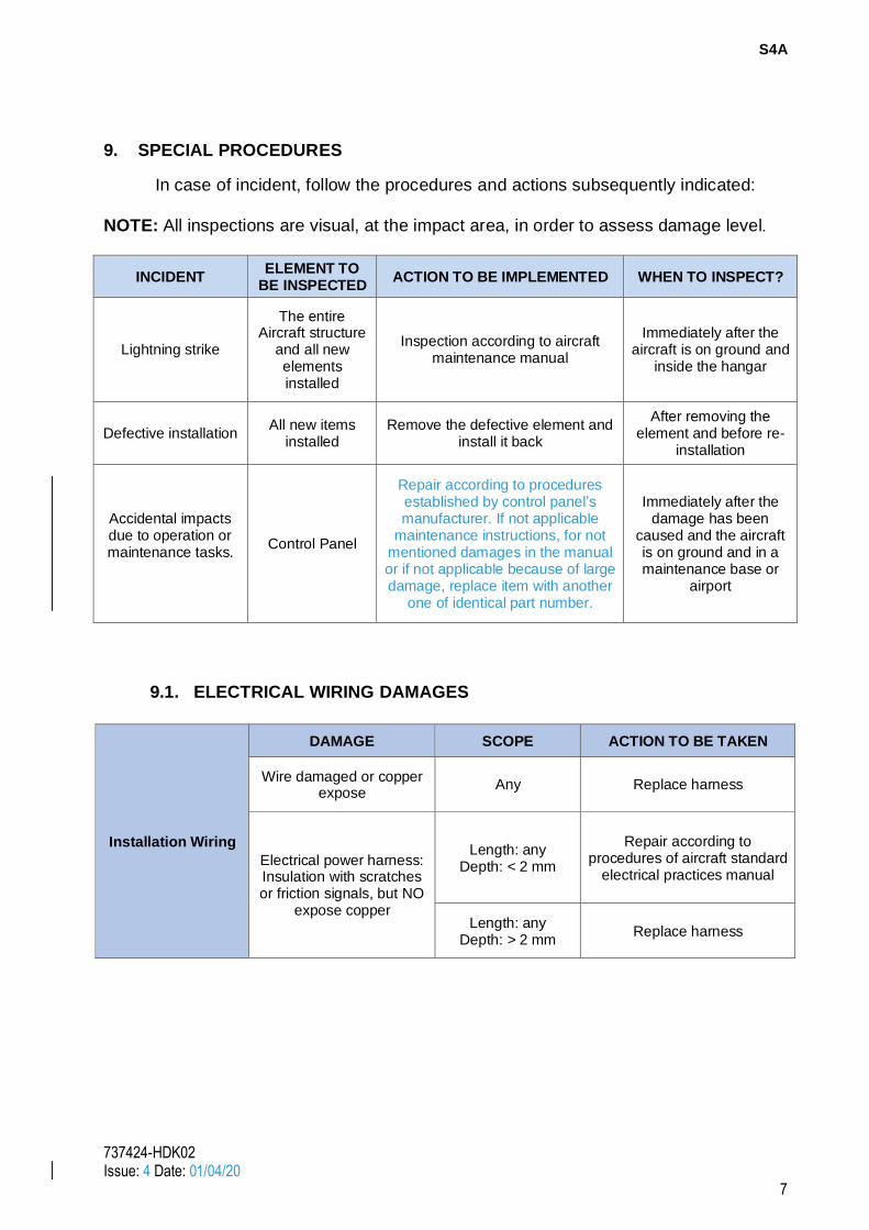
9. SPECIAL PROCEDURES
In case of incident, follow the procedures and actions subsequently indicated:
NOTE: All inspections are visual, at the impact area, in order to assess damage level.
INCIDENT ELEMENT TO
BE INSPECTED ACTION TO BE IMPLEMENTED WHEN TO INSPECT?
Lightning strike
The entire Aircraft structure
and all new elements installed
Inspection according to aircraft maintenance manual
Immediately after the aircraft is on ground and
inside the hangar
Defective installation All new items
installed Remove the defective element and
install it back
After removing the element and before re-
installation
Accidental impacts due to operation or maintenance tasks.
Control Panel
Repair according to procedures established by control panel’s manufacturer. If not applicable
maintenance instructions, for not mentioned damages in the manual or if not applicable because of large damage, replace item with another
one of identical part number.
Immediately after the damage has been
caused and the aircraft is on ground and in a maintenance base or
airport
9.1. ELECTRICAL WIRING DAMAGES
Installation Wiring
DAMAGE SCOPE ACTION TO BE TAKEN
Wire damaged or copper expose
Any Replace harness
Electrical power harness: Insulation with scratches or friction signals, but NO
expose copper
Length: any Depth: < 2 mm
Repair according to procedures of aircraft standard
electrical practices manual
Length: any Depth: > 2 mm
Replace harness
S4A
737424-HDK02 Issue: 4 Date: 01/04/20
8
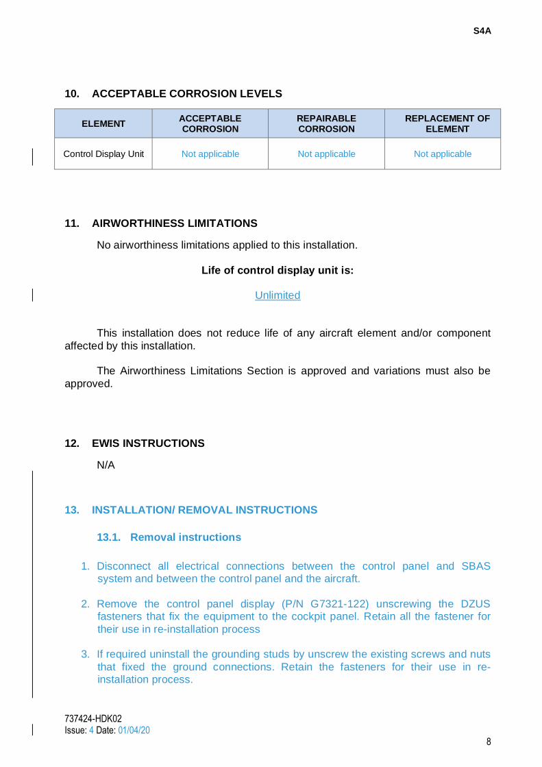
10. ACCEPTABLE CORROSION LEVELS
ELEMENT ACCEPTABLE CORROSION
REPAIRABLE CORROSION
REPLACEMENT OF ELEMENT
Control Display Unit Not applicable Not applicable Not applicable
11. AIRWORTHINESS LIMITATIONS
No airworthiness limitations applied to this installation.
Life of control display unit is:
Unlimited
This installation does not reduce life of any aircraft element and/or component
affected by this installation.
The Airworthiness Limitations Section is approved and variations must also be
approved.
12. EWIS INSTRUCTIONS
N/A
13. INSTALLATION/ REMOVAL INSTRUCTIONS
13.1. Removal instructions
1. Disconnect all electrical connections between the control panel and SBAS
system and between the control panel and the aircraft.
2. Remove the control panel display (P/N G7321-122) unscrewing the DZUS
fasteners that fix the equipment to the cockpit panel. Retain all the fastener for
their use in re-installation process
3. If required uninstall the grounding studs by unscrew the existing screws and nuts
that fixed the ground connections. Retain the fasteners for their use in re-installation process.
S4A
737424-HDK02 Issue: 4 Date: 01/04/20
9
13.2. Installation instructions
1. If the ground connection where removed during the removal process install them
back in the location where it was installed previous the removal. Ensure the
fasteners used are exactly the same as in the original modification.
2. Attach the control display unit to the instruments panel according by means of
DZUS fasteners. Ensure the fasteners are in the same location as before the removal.
3. Connect all electrical connections between the control panel and SBAS system and between control panel and aircraft electrical system.