Multifield Variational Finite Element Sectional Analysis ...
7
Vol. 30, No. 6, 343-349 (2017) DOI: http://dx.doi.org/10.7234/composres.2017.30.6.343 ISSN 2288-2103(Print), ISSN 2288-2111(Online) Paper Multifield Variational Finite Element Sectional Analysis of Composite Beams Manoj Kumar Dhadwal * , Sung Nam Jung * † ABSTRACT: A multifield variational formulation is developed for the finite element (FE) cross-sectional analysis of composite beams. The cross-sectional warping displacements and sectional stresses are considered to be the primary variables through the application of Reissner’s partially mixed principle. The warping displacements are modeled using generic FE shape functions with nonlinear distribution over the beam section. A generalized Timoshenko level stiffness matrix is derived which incorporates the effects of elastic couplings, transverse shear, and Poisson’s deformations. The accuracy of the present analysis is validated for the stiffness constants and elastostatic responses of composite box beams which correlate well with the experimental data and other state-of-the-art approaches. Key Words: Composite beam, Cross-section, Multifield principle, 3D warping 1. INTRODUCTION Composite structures offer a wide variety of advantages in various engineering fields due to their high stiffness-to-weight ratio. The composite materials provide a convenient way to tailor the structural characteristics by defining the required ply layup. Beam theories have gained a lot of attention in the past decades due to the efficient modeling and analysis of com- posite slender structures. The three-dimensional (3D) analysis of composite beams is generally decomposed into two-dimen- sional (2D) sectional and one-dimensional (1D) beam anal- yses [1,2]. Such a decomposition approach is useful for the preliminary design and optimization of slender composite structures. Beam cross-sectional analyses are mainly categorized into FE and analytical formulations based on the implementation. The former offers advantage in that any arbitrary geometry with complex material distribution can be modeled in detail while the latter is limited to only simple cross-sections. Giavotto et al. [3] developed a FE cross-sectional analysis for generally anisotropic beams based on central and extremity solutions. The central solution was used to compute a Timos- henko level stiffness matrix with elastic couplings. Cesnik and Hodges [4] proposed a variational asymptotic beam sectional analysis to compute stiffness constants formulated based on the variational asymptotic method of Berdischevsky [5]. Chandra et al. [6] and Chandra and Chopra [7] developed an analytical formulation with simple expressions for sectional stiffness constants. They also conducted experimental tests to investigate the effect of elastic couplings on the 1D elastostatic response of composite beams and blades. Jung et al. [8] pre- sented a mixed shell-wall based analytical force-displacement approach to determine the sectional stiffness constants at Timoshenko-Vlasov level. Most of the studies mentioned previously adopted a dis- placement-based approach with displacements as the only pri- mary variables which typically results in low accuracy of stresses. Multifield formulations as proposed by Reissner [9] involving stresses as additional unknown variables can over- come this limitation with more computational effort. In addi- tion, implementation of cross-sectional formulation into a FE analysis can offer the accurate modeling of complex geometric features and composite material layups of beams. The present work deals with the development of a FE based multifield variational sectional analysis code (MVSAC) for nonhomogeneous anisotropic beams with arbitrary geometry Received 3 August 2017, received in revised form 26 December 2017, accepted 27 December 2017 * * Department of Aerospace Information Engineering, Konkuk University Department of Aerospace Information Engineering, Konkuk University, Corresponding author (E-mail: [email protected])
Transcript of Multifield Variational Finite Element Sectional Analysis ...

Vol. 30, No. 6, 343-349 (2017)DOI: http://dx.doi.org/10.7234/composres.2017.30.6.343ISSN 2288-2103(Print), ISSN 2288-2111(Online)
Paper
Multifield Variational Finite Element Sectional Analysis of Composite Beams
Manoj Kumar Dhadwal*, Sung Nam Jung*†
ABSTRACT: A multifield variational formulation is developed for the finite element (FE) cross-sectional analysis ofcomposite beams. The cross-sectional warping displacements and sectional stresses are considered to be the primaryvariables through the application of Reissner’s partially mixed principle. The warping displacements are modeled usinggeneric FE shape functions with nonlinear distribution over the beam section. A generalized Timoshenko levelstiffness matrix is derived which incorporates the effects of elastic couplings, transverse shear, and Poisson’sdeformations. The accuracy of the present analysis is validated for the stiffness constants and elastostatic responses ofcomposite box beams which correlate well with the experimental data and other state-of-the-art approaches.
Key Words: Composite beam, Cross-section, Multifield principle, 3D warping
1. INTRODUCTION
Composite structures offer a wide variety of advantages invarious engineering fields due to their high stiffness-to-weightratio. The composite materials provide a convenient way totailor the structural characteristics by defining the required plylayup. Beam theories have gained a lot of attention in the pastdecades due to the efficient modeling and analysis of com-posite slender structures. The three-dimensional (3D) analysisof composite beams is generally decomposed into two-dimen-sional (2D) sectional and one-dimensional (1D) beam anal-yses [1,2]. Such a decomposition approach is useful for thepreliminary design and optimization of slender compositestructures.
Beam cross-sectional analyses are mainly categorized intoFE and analytical formulations based on the implementation.The former offers advantage in that any arbitrary geometrywith complex material distribution can be modeled in detailwhile the latter is limited to only simple cross-sections.Giavotto et al. [3] developed a FE cross-sectional analysis forgenerally anisotropic beams based on central and extremitysolutions. The central solution was used to compute a Timos-henko level stiffness matrix with elastic couplings. Cesnik and
Hodges [4] proposed a variational asymptotic beam sectionalanalysis to compute stiffness constants formulated based onthe variational asymptotic method of Berdischevsky [5].Chandra et al. [6] and Chandra and Chopra [7] developed ananalytical formulation with simple expressions for sectionalstiffness constants. They also conducted experimental tests toinvestigate the effect of elastic couplings on the 1D elastostaticresponse of composite beams and blades. Jung et al. [8] pre-sented a mixed shell-wall based analytical force-displacementapproach to determine the sectional stiffness constants atTimoshenko-Vlasov level.
Most of the studies mentioned previously adopted a dis-placement-based approach with displacements as the only pri-mary variables which typically results in low accuracy ofstresses. Multifield formulations as proposed by Reissner [9]involving stresses as additional unknown variables can over-come this limitation with more computational effort. In addi-tion, implementation of cross-sectional formulation into a FEanalysis can offer the accurate modeling of complex geometricfeatures and composite material layups of beams.
The present work deals with the development of a FE basedmultifield variational sectional analysis code (MVSAC) fornonhomogeneous anisotropic beams with arbitrary geometry
Received 3 August 2017, received in revised form 26 December 2017, accepted 27 December 2017
*
*†
Department of Aerospace Information Engineering, Konkuk University Department of Aerospace Information Engineering, Konkuk University, Corresponding author (E-mail: [email protected])
344 Manoj Kumar Dhadwal, Sung Nam Jung
and material distribution. The sectional stresses (called as reac-tive stresses [9]) are assumed to be unknowns in addition to 3Dsectional warping displacements. The transverse shear andPoisson’s deformation effects are inherently taken into accountthrough the 3D warping. A 6×6 generalized Timoshenko stiff-ness matrix is obtained incorporating the classical and non-classical elastic couplings. The stiffness constants and 1Delastostatic response computed by the present analysis is val-idated for composite beams with elastic couplings.
2. MULTIFIELD CROSS-SECTIONAL ANAL-YSIS
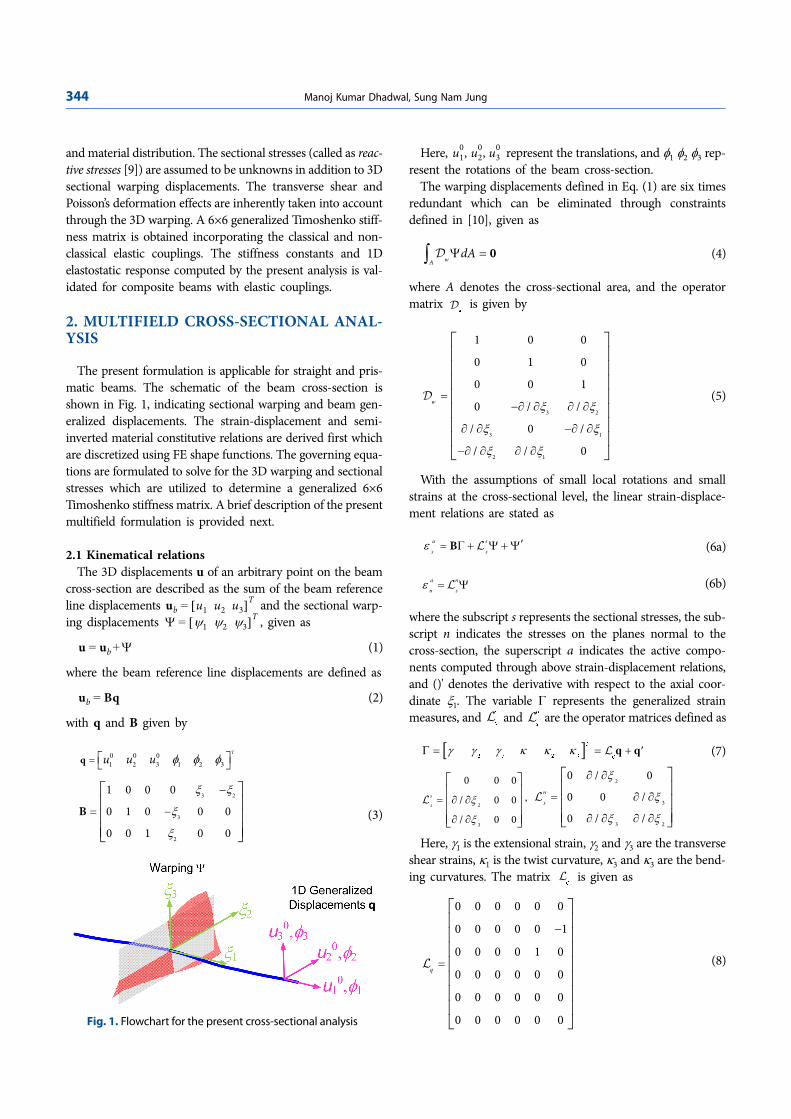
The present formulation is applicable for straight and pris-matic beams. The schematic of the beam cross-section isshown in Fig. 1, indicating sectional warping and beam gen-eralized displacements. The strain-displacement and semi-inverted material constitutive relations are derived first whichare discretized using FE shape functions. The governing equa-tions are formulated to solve for the 3D warping and sectionalstresses which are utilized to determine a generalized 6×6Timoshenko stiffness matrix. A brief description of the presentmultifield formulation is provided next.
2.1 Kinematical relationsThe 3D displacements u of an arbitrary point on the beam
cross-section are described as the sum of the beam referenceline displacements and the sectional warp-ing displacements , given as
(1)
where the beam reference line displacements are defined as
(2)
with q and B given by
(3)
Here, represent the translations, and φ1 φ2 φ3 rep-resent the rotations of the beam cross-section.
The warping displacements defined in Eq. (1) are six timesredundant which can be eliminated through constraintsdefined in [10], given as
(4)
where A denotes the cross-sectional area, and the operatormatrix is given by
(5)
With the assumptions of small local rotations and smallstrains at the cross-sectional level, the linear strain-displace-ment relations are stated as
(6a)
(6b)
where the subscript s represents the sectional stresses, the sub-script n indicates the stresses on the planes normal to thecross-section, the superscript a indicates the active compo-nents computed through above strain-displacement relations,and ()' denotes the derivative with respect to the axial coor-dinate ξ1. The variable Γ represents the generalized strainmeasures, and and are the operator matrices defined as
(7)
,
Here, γ1 is the extensional strain, γ2 and γ3 are the transverseshear strains, κ1 is the twist curvature, κ3 and κ3 are the bend-ing curvatures. The matrix is given as
(8)
ub u1 u2 u3[ ]T
=
Ψ ψ1 ψ2 ψ3[ ]T
=
u ub Ψ+=
ub Bq=
0 0 01 2 3 1 2 3
T
u u u φ φ φ= ⎡ ⎤⎣ ⎦q
3 2
3
2
1 0 0 0
0 1 0 0 0
0 0 1 0 0
ξ ξ
ξ
ξ
−
= −
⎡ ⎤⎢ ⎥⎢ ⎥⎢ ⎥⎣ ⎦
B
u10, u2
0, u30
wAdAΨ =∫ 0D
w
D
3 2
3 1
2 1
1 0 0
0 1 0
0 0 1
0 / /
/ 0 /
/ / 0
wξ ξ
ξ ξ
ξ ξ
−∂ ∂ ∂ ∂
∂ ∂ −∂ ∂
=
−∂ ∂ ∂ ∂
⎡ ⎤⎢ ⎥⎢ ⎥⎢ ⎥⎢ ⎥⎢ ⎥⎢ ⎥⎢ ⎥⎣ ⎦
D
a s
s sε ′= Γ + Ψ + ΨB L
a n
n sε = ΨL
s
s
Ln
s
L
[ ]1 2 3 1 2 3
γ γ γ κ κ κΓ = = + ′T
qq qL
2
3
0 0 0
/ 0 0
/ 0 0
s
s ξ
ξ
= ∂ ∂
∂ ∂
⎡ ⎤⎢ ⎥⎢ ⎥⎢ ⎥⎣ ⎦
L
2
3
3 2
0 / 0
0 0 /
0 / /
n
s
ξ
ξ
ξ ξ
∂ ∂
= ∂ ∂
∂ ∂ ∂ ∂
⎡ ⎤⎢ ⎥⎢ ⎥⎢ ⎥⎣ ⎦
L
qL
0 0 0 0 0 0
0 0 0 0 0 1
0 0 0 0 1 0
0 0 0 0 0 0
0 0 0 0 0 0
0 0 0 0 0 0
q
−
=
⎡ ⎤⎢ ⎥⎢ ⎥⎢ ⎥⎢ ⎥⎢ ⎥⎢ ⎥⎢ ⎥⎣ ⎦
L
Fig. 1. Flowchart for the present cross-sectional analysis

Multifield Variational Finite Element Sectional Analysis of Composite Beams 345
2.2 Semi-inverted material constitutive relationsFor a linearly elastic anisotropic material, the constitutive
relations in the material coordinate system are defined usinggeneralized Hooke’s law as
(9)
where σm denotes the stress vector, εm denotes the strain vec-tor, and Cm is the material constitutive matrix. These consti-tutive relations can be transformed to the beam coordinatesystem through transformation by fiber angle and fiber planeangle for composite materials. The sectional stresses (one nor-mal and two transverse shear components) in the present for-mulation are considered to be unknowns, and hereafter calledas reactive sectional stresses. Therefore, the material constitutiverelations are expressed in a semi-inverted form as given by
(10)
where the superscript r denotes the reactive sectional stresseswhich are directly computed from the multifield formulationwhereas the superscript a denotes the remaining active stressescomputed through kinematical relations.
2.3 Finite element discretizationThe warping displacements and the reactive sectional
stresses are discretized using isoparametric FE shape functionsas
(11a)
(11b)
where and are respectively the nodal values of warpingdisplacements and reactive stresses, and N
ψ and N
σ are the
respective FE shape functions.The warping constraints from Eq. (4) are expressed in dis-
cretized form as
(12)
where Dψ is the warping constraint matrix.
2.4 Governing equationsThe present multifield formulation considers sectional
stresses and displacements as primary variables. The variationof total energy per unit beam length is expressed as
(13)
where δUs is the variation of cross-sectional strain energy, δWis the variation of external work due to applied loads, and δL is
the variation of warping constraints obtained from Eq. (12)using Lagrange multipliers Θ
ψ, as given by
(14)
The generalized form of Reissner’s semi-complimentaryenergy functional ΦR [9] is stated as
(15)
The cross-sectional strain energy is defined using ΦR as
(16)
The active strains from kinematical relations and thereactive strains from semi-inverted material constitutiverelations must be compatible, implying . The variationof sectional strain energy is then obtained as
(17)
Substituting Eqs. (6), (10), and (11) into the above equation,the sectional strain energy becomes
(18)
where the matrices A, E, G, H, and R include the couplingsdue to geometry and material distribution of the beam section,given as
,
, (19)
The sectional stress resultants are defined as
(20)
where
(21)
Here, F1 indicates the extensional force, F2 and F3 representthe transverse shear forces, M1 represents the torsional moment,and M2 and M3 denote the bending moments.
Neglecting surface and body forces, the external work per
m m mσ ε= C
r rss sn
s s
Ta asn nnn n
ε σ
σ ε
=
−
⎡ ⎤⎧ ⎫ ⎧ ⎫⎪ ⎪ ⎪ ⎪⎢ ⎥⎨ ⎬ ⎨ ⎬
⎪ ⎪ ⎪ ⎪⎢ ⎥⎩ ⎭ ⎩ ⎭⎣ ⎦
C C
C C
1 2 3 2 3 1( , , ) ( , ) ( )ψ
ξ ξ ξ ξ ξ ξΨ = ΛN
1 2 3 2 3 1( , , ) ( , ) ( )r
s σ
σ ξ ξ ξ ξ ξ ξ= ϒN
Λ ϒ
( )wAdA
ψ ψΛ = Λ =∫ N D 0D
R s sU W Lδ δ δ δΠ = − =
( )T T TLψ ψ ψ ψ
δ δ δ= − Λ Θ − Θ ΛD D
( )1
( ) ( )2
a T a r T r
R n n s sε σ σ εΦ = −
( )r T r
s R s sAU dAε σ= Φ +⎡ ⎤⎣ ⎦∫
εsa
εsr
εsr
εsa
=
( )( ) ( ) ( )a T a a T r r T a r
s n n s s s s sAU dAδ δε σ δε σ δσ ε ε= + + −⎡ ⎤⎣ ⎦∫
T
T T
s
T
U
ψ ψ
δ
δ
δδ
δ
δ
′ ′Λ Λ
Υ − Υ
Λ Λ=
Γ Γ
Θ Θ
⎡ ⎤⎧ ⎫ ⎧ ⎫⎢ ⎥⎪ ⎪ ⎪ ⎪⎢ ⎥⎪ ⎪ ⎪ ⎪⎪ ⎪ ⎪ ⎪⎢ ⎥⎨ ⎬ ⎨ ⎬⎢ ⎥⎪ ⎪ ⎪ ⎪⎢ ⎥⎪ ⎪ ⎪ ⎪⎢ ⎥⎪ ⎪ ⎪ ⎪⎩ ⎭ ⎩ ⎭⎣ ⎦
0 A 0 0 0
A H G R 0
0 G E 0 0
0 R 0 0 0
0 0 0 0 0
T
A
dAψ σ
= ∫A N N ( )Tn n
s nn sAdA
ψ ψ= ∫E N C NL L
( )Ts n
s sn sAdA
ψ ψ σ= −∫G N C N NL L
T
ssAdA
σ σ
= ∫H N C N T
A
dAσ
= ∫R N B
T
sAdAσ= ∫F B
1 2 3 1 2 3
T
F F F M M M= ⎡ ⎤⎣ ⎦F
346 Manoj Kumar Dhadwal, Sung Nam Jung
unit beam length is stated as
(22)
Substituting Eqs. (1), (2), (11), and (20) into the above equa-tion, the variation of external work can be obtained as
(23)
where
, (24)
2.5 Warping solution and stiffness matrixThe warping displacements and the reactive stresses are
approximated as linear functions of sectional stress resultants,as given by
(25)
(26)
where and respectively indicate the nodal values ofwarping and reactive stress coefficients, and indicates thebeam strain measure coefficients which are constant over thesectional area. The variables with subscript p represent thenodal coefficients corresponding to the derivatives of gener-alized strain measures. The coefficients matrices incorporatethe contributions from extension, shear, bending and torsionof the beam section.
Using the approximations of warping and reactive stressesfrom Eq. (11), and substituting Eqs. (14), (18), and (23) intoEq. (13), the equilibrium equations are obtained as
(27a)
(27b)
The warping and reactive stress coefficients are solved usingthe above set of equations.
The strain energy variation from Eq. (18) can then beupdated as
(28)
The external work variation can be expressed in terms ofgeneralized Timoshenko like sectional stiffness matrix as
(29)
Using the energy principle defined in Eq. (13), the 6×6Timoshenko like stiffness matrix is determined as
(30)
The above stiffness matrix considers the elastic couplingseffects including transverse shear and Poisson’s deformations,and can be fully populated for generally anisotropic beams.
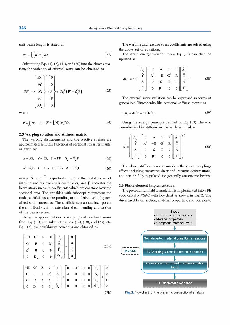
2.6 Finite element implementationThe present multifield formulation is implemented into a FE
code called MVSAC with flowchart as shown in Fig. 2. Thediscretized beam section, material properties, and composite
( )T
s sAW dAσ
′
= ∫ u
( )
T
T T
s qW
ψ
δ
δ
δδ δ
δ
δ
′Λ
Υ
Λ ′= + ′ −
Γ
Θ
⎧ ⎫ ⎧ ⎫⎪ ⎪ ⎪ ⎪⎪ ⎪ ⎪ ⎪⎪ ⎪ ⎪ ⎪⎨ ⎬ ⎨ ⎬⎪ ⎪ ⎪ ⎪⎪ ⎪ ⎪ ⎪⎪ ⎪ ⎪ ⎪⎩ ⎭ ⎩ ⎭
P
0
P q F F
F
0
L
T
sAdA
ψσ= ∫P N ( )T
sAdA
ψσ′ = ′∫P N
, , ,ψ ψ
Λ = Λ ϒ = ϒ Γ = Γ Θ = ΘF F F F% % %%
, , ,p p p pψ ψΛ′ = Λ ϒ′ = ϒ Γ′ = Γ Θ′ = ΘF F F F% % %%
Λ% ϒ%
Γ%
T
p
Tp
TTp q
p
ψ
ψψ
−
Λ
ϒ
=Γ
Θ
⎡ ⎤ ⎡ ⎤⎡ ⎤⎢ ⎥ ⎢ ⎥⎢ ⎥⎢ ⎥ ⎢ ⎥⎢ ⎥⎢ ⎥ ⎢ ⎥⎢ ⎥⎢ ⎥ ⎢ ⎥⎢ ⎥⎢ ⎥ ⎣ ⎦ ⎣ ⎦⎣ ⎦
H G R 0 0
0G E 0 D
R 0 0 000 D 0 0
%
%
%
%
L
T Tp
Tp
Tp
p
ψ
ψψψ
− −
ΛΛ
= +ΓΓ
ϒϒ
ΘΘ
⎡ ⎤ ⎡ ⎤ ⎡ ⎤⎡ ⎤ ⎡ ⎤⎢ ⎥ ⎢ ⎥ ⎢ ⎥⎢ ⎥ ⎢ ⎥⎢ ⎥ ⎢ ⎥ ⎢ ⎥⎢ ⎥ ⎢ ⎥⎢ ⎥ ⎢ ⎥ ⎢ ⎥⎢ ⎥ ⎢ ⎥⎢ ⎥ ⎢ ⎥ ⎢ ⎥⎢ ⎥ ⎢ ⎥⎢ ⎥ ⎣ ⎦ ⎣ ⎦⎣ ⎦⎣ ⎦⎣ ⎦
H G R 0 00 A 0 0
0G E 0 D A 0 0 0
I0 0 0 0R 0 0 000 0 0 00 D 0 0
%
%
%
%
%
%
%
%
T
p p
T T
T
s
T
Uδ δ
Λ Λ
−
=Λ Λ
Γ Γ
ϒ ϒ
⎡ ⎤⎡ ⎤ ⎡ ⎤⎢ ⎥⎢ ⎥ ⎢ ⎥⎢ ⎥⎢ ⎥ ⎢ ⎥⎢ ⎥⎢ ⎥ ⎢ ⎥⎢ ⎥⎢ ⎥ ⎢ ⎥⎢ ⎥⎣ ⎦ ⎣ ⎦⎣ ⎦
0 A 0 0
A H G RF F
0 G E 0
0 R 0 0
% %
% %
%
% %
%
1T T
sWδ δ δ−
= Γ =F F K F
1T
p p
T T
T
−
Λ Λ
−
Λ
Γ
ϒ
Λ
Γ
ϒ
=
⎛ ⎞⎡ ⎤⎡ ⎤ ⎡ ⎤⎜ ⎟⎢ ⎥⎢ ⎥ ⎢ ⎥⎜ ⎟⎢ ⎥⎢ ⎥ ⎢ ⎥⎜ ⎟⎢ ⎥⎢ ⎥ ⎢ ⎥⎜ ⎟⎢ ⎥⎢ ⎥ ⎢ ⎥⎜ ⎟⎢ ⎥⎣ ⎦ ⎣ ⎦⎣ ⎦⎝ ⎠
0 A 0 0
A H G RK
0 G E 0
0 R 0 0
% %
% %
% %
% %
Fig. 2. Flowchart for the present cross-sectional analysis
Multifield Variational Finite Element Sectional Analysis of Composite Beams 347
layup are provided as input to the analysis. The semi-invertedmaterial constitutive relations are first computed, as given inEq. (10). The 3D warping deformation and reactive stresscoefficients are then calculated using Eq. (27) which are usedto compute the generalized 6×6 Timoshenko like stiffnessmatrix in Eq. (30).
3. RESULTS AND DISCUSSION
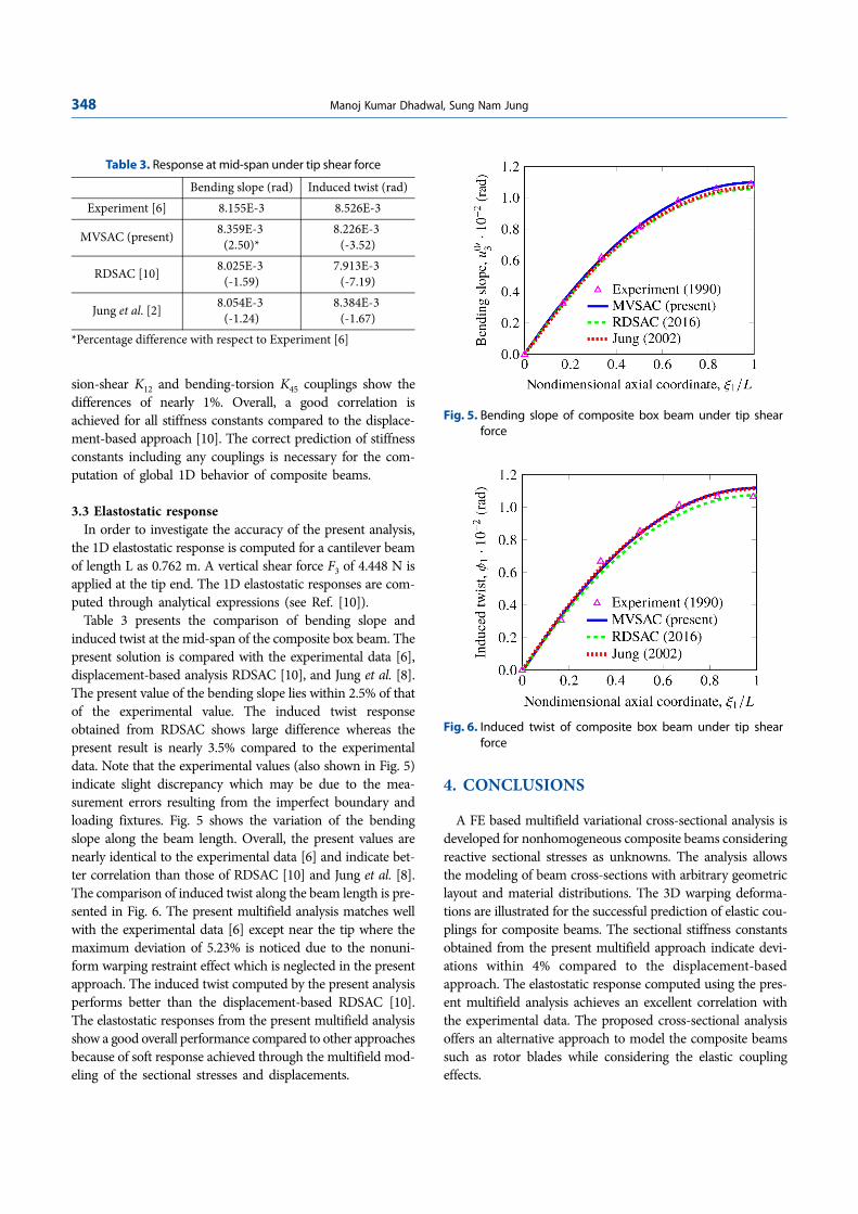
The present analysis MVSAC is validated for an elasticallycoupled composite box beam with a circumferentially anti-symmetric layup [6], as shown in Fig. 3. The material prop-erties are given in Table 1 [6]. The section is discretized with360 eight-node quadrilateral elements and 1,200 nodes givinga total of 7,200 degrees of freedom. The commercial softwareMSC Patran is used for the FE discretization. The sectionexhibits bending-torsion and extension-shear couplings.
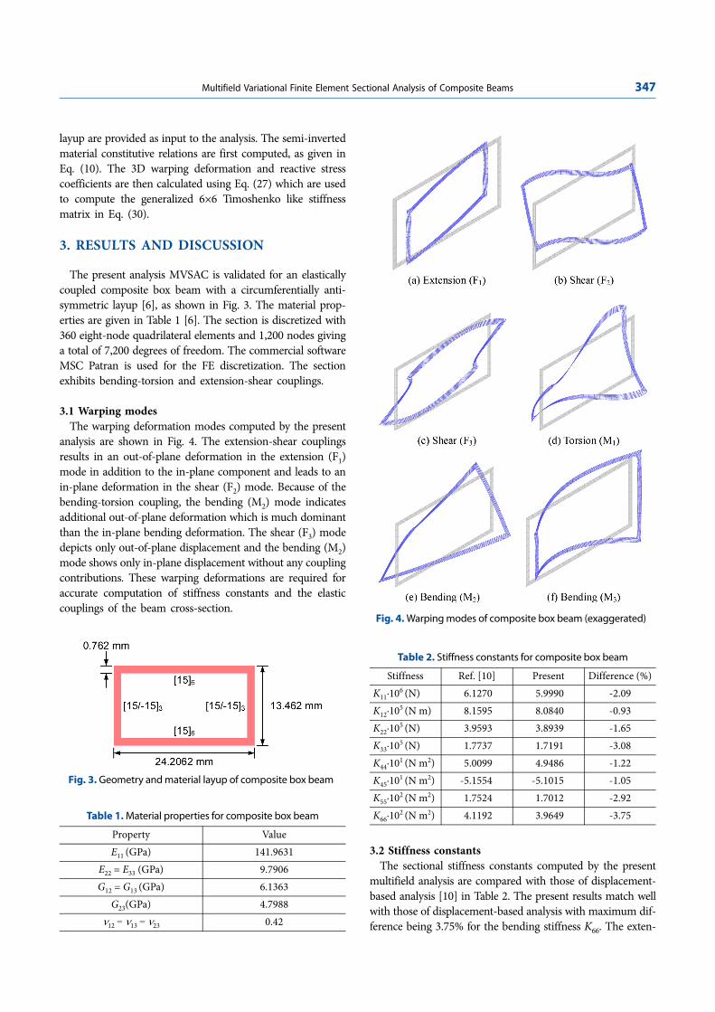
3.1 Warping modesThe warping deformation modes computed by the present
analysis are shown in Fig. 4. The extension-shear couplingsresults in an out-of-plane deformation in the extension (F1)mode in addition to the in-plane component and leads to anin-plane deformation in the shear (F2) mode. Because of thebending-torsion coupling, the bending (M2) mode indicatesadditional out-of-plane deformation which is much dominantthan the in-plane bending deformation. The shear (F3) modedepicts only out-of-plane displacement and the bending (M2)mode shows only in-plane displacement without any couplingcontributions. These warping deformations are required foraccurate computation of stiffness constants and the elasticcouplings of the beam cross-section.
3.2 Stiffness constantsThe sectional stiffness constants computed by the present
multifield analysis are compared with those of displacement-based analysis [10] in Table 2. The present results match wellwith those of displacement-based analysis with maximum dif-ference being 3.75% for the bending stiffness K66. The exten-
Table 1. Material properties for composite box beam
Property ValueE11 (GPa) 141.9631
E22 = E33 (GPa) 9.7906G12 = G13 (GPa) 6.1363
G23(GPa) 4.7988ν12 = ν13 = ν23 0.42
Fig. 3. Geometry and material layup of composite box beam
Fig. 4. Warping modes of composite box beam (exaggerated)
Table 2. Stiffness constants for composite box beam
Stiffness Ref. [10] Present Difference (%)K11·106 (N) 6.1270 5.9990 -2.09K12·105 (N m) 8.1595 8.0840 -0.93K22·105 (N) 3.9593 3.8939 -1.65K33·105 (N) 1.7737 1.7191 -3.08K44·101 (N m2) 5.0099 4.9486 -1.22K45·101 (N m2) -5.1554 -5.1015 -1.05K55·102 (N m2) 1.7524 1.7012 -2.92K66·102 (N m2) 4.1192 3.9649 -3.75
348 Manoj Kumar Dhadwal, Sung Nam Jung
sion-shear K12 and bending-torsion K45 couplings show thedifferences of nearly 1%. Overall, a good correlation isachieved for all stiffness constants compared to the displace-ment-based approach [10]. The correct prediction of stiffnessconstants including any couplings is necessary for the com-putation of global 1D behavior of composite beams.
3.3 Elastostatic responseIn order to investigate the accuracy of the present analysis,
the 1D elastostatic response is computed for a cantilever beamof length L as 0.762 m. A vertical shear force F3 of 4.448 N isapplied at the tip end. The 1D elastostatic responses are com-puted through analytical expressions (see Ref. [10]).
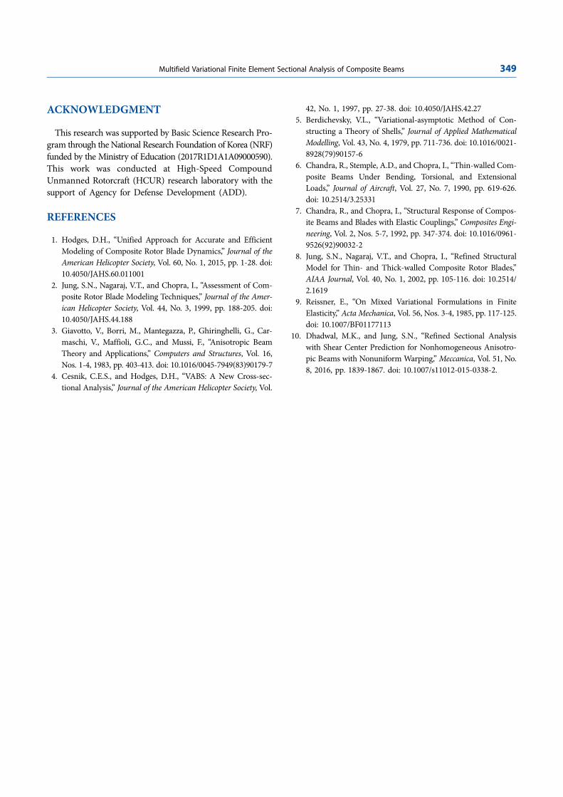
Table 3 presents the comparison of bending slope andinduced twist at the mid-span of the composite box beam. Thepresent solution is compared with the experimental data [6],displacement-based analysis RDSAC [10], and Jung et al. [8].The present value of the bending slope lies within 2.5% of thatof the experimental value. The induced twist responseobtained from RDSAC shows large difference whereas thepresent result is nearly 3.5% compared to the experimentaldata. Note that the experimental values (also shown in Fig. 5)indicate slight discrepancy which may be due to the mea-surement errors resulting from the imperfect boundary andloading fixtures. Fig. 5 shows the variation of the bendingslope along the beam length. Overall, the present values arenearly identical to the experimental data [6] and indicate bet-ter correlation than those of RDSAC [10] and Jung et al. [8].The comparison of induced twist along the beam length is pre-sented in Fig. 6. The present multifield analysis matches wellwith the experimental data [6] except near the tip where themaximum deviation of 5.23% is noticed due to the nonuni-form warping restraint effect which is neglected in the presentapproach. The induced twist computed by the present analysisperforms better than the displacement-based RDSAC [10].The elastostatic responses from the present multifield analysisshow a good overall performance compared to other approachesbecause of soft response achieved through the multifield mod-eling of the sectional stresses and displacements.
4. CONCLUSIONS
A FE based multifield variational cross-sectional analysis isdeveloped for nonhomogeneous composite beams consideringreactive sectional stresses as unknowns. The analysis allowsthe modeling of beam cross-sections with arbitrary geometriclayout and material distributions. The 3D warping deforma-tions are illustrated for the successful prediction of elastic cou-plings for composite beams. The sectional stiffness constantsobtained from the present multifield approach indicate devi-ations within 4% compared to the displacement-basedapproach. The elastostatic response computed using the pres-ent multifield analysis achieves an excellent correlation withthe experimental data. The proposed cross-sectional analysisoffers an alternative approach to model the composite beamssuch as rotor blades while considering the elastic couplingeffects.
Table 3. Response at mid-span under tip shear force
Bending slope (rad) Induced twist (rad)Experiment [6] 8.155E-3 8.526E-3
MVSAC (present) 8.359E-3 (2.50)*
8.226E-3 (-3.52)
RDSAC [10] 8.025E-3 (-1.59)
7.913E-3 (-7.19)
Jung et al. [2] 8.054E-3 (-1.24)
8.384E-3 (-1.67)
*Percentage difference with respect to Experiment [6]
Fig. 5. Bending slope of composite box beam under tip shearforce
Fig. 6. Induced twist of composite box beam under tip shearforce
Multifield Variational Finite Element Sectional Analysis of Composite Beams 349
ACKNOWLEDGMENT
This research was supported by Basic Science Research Pro-gram through the National Research Foundation of Korea (NRF)funded by the Ministry of Education (2017R1D1A1A09000590).This work was conducted at High-Speed CompoundUnmanned Rotorcraft (HCUR) research laboratory with thesupport of Agency for Defense Development (ADD).
REFERENCES
1. Hodges, D.H., “Unified Approach for Accurate and EfficientModeling of Composite Rotor Blade Dynamics,” Journal of theAmerican Helicopter Society, Vol. 60, No. 1, 2015, pp. 1-28. doi:10.4050/JAHS.60.011001
2. Jung, S.N., Nagaraj, V.T., and Chopra, I., “Assessment of Com-posite Rotor Blade Modeling Techniques,” Journal of the Amer-ican Helicopter Society, Vol. 44, No. 3, 1999, pp. 188-205. doi:10.4050/JAHS.44.188
3. Giavotto, V., Borri, M., Mantegazza, P., Ghiringhelli, G., Car-maschi, V., Maffioli, G.C., and Mussi, F., “Anisotropic BeamTheory and Applications,” Computers and Structures, Vol. 16,Nos. 1-4, 1983, pp. 403-413. doi: 10.1016/0045-7949(83)90179-7
4. Cesnik, C.E.S., and Hodges, D.H., “VABS: A New Cross-sec-tional Analysis,” Journal of the American Helicopter Society, Vol.
42, No. 1, 1997, pp. 27-38. doi: 10.4050/JAHS.42.275. Berdichevsky, V.L., “Variational-asymptotic Method of Con-
structing a Theory of Shells,” Journal of Applied MathematicalModelling, Vol. 43, No. 4, 1979, pp. 711-736. doi: 10.1016/0021-8928(79)90157-6
6. Chandra, R., Stemple, A.D., and Chopra, I., “Thin-walled Com-posite Beams Under Bending, Torsional, and ExtensionalLoads,” Journal of Aircraft, Vol. 27, No. 7, 1990, pp. 619-626.doi: 10.2514/3.25331
7. Chandra, R., and Chopra, I., “Structural Response of Compos-ite Beams and Blades with Elastic Couplings,” Composites Engi-neering, Vol. 2, Nos. 5-7, 1992, pp. 347-374. doi: 10.1016/0961-9526(92)90032-2
8. Jung, S.N., Nagaraj, V.T., and Chopra, I., “Refined StructuralModel for Thin- and Thick-walled Composite Rotor Blades,”AIAA Journal, Vol. 40, No. 1, 2002, pp. 105-116. doi: 10.2514/2.1619
9. Reissner, E., “On Mixed Variational Formulations in FiniteElasticity,” Acta Mechanica, Vol. 56, Nos. 3-4, 1985, pp. 117-125.doi: 10.1007/BF01177113
10. Dhadwal, M.K., and Jung, S.N., “Refined Sectional Analysiswith Shear Center Prediction for Nonhomogeneous Anisotro-pic Beams with Nonuniform Warping,” Meccanica, Vol. 51, No.8, 2016, pp. 1839-1867. doi: 10.1007/s11012-015-0338-2.


![A Primer on Geometric Mechanics [5pt] Variational ...isg › graphics › teaching › 2012 › gm_prime… · Variational mechanics Reduced variational principles: Euler-Poincar](https://static.fdocuments.in/doc/165x107/5f22c835dfb9dc685a64123f/a-primer-on-geometric-mechanics-5pt-variational-a-graphics-a-teaching.jpg)