Multicopter collision detection - Excel@FIT 2017excel.fit.vutbr.cz/submissions/2015/074/74.pdf ·...
5
2015 http://excel.fit.vutbr.cz Multicopter collision avoidance system Radim Hrazdil* Abstract There are a lot of people who like making models of planes, helicopters or multicopters, but not all of them can actually fly them. This article presents (HW/SW) system that prevents user from crashing into obstacles and provides convenient way to control any UAV (Unmanned Aerial Vehicle). The main target are vehicles equipped with Robotic operating system (ROS), however the device is designed to be easy to use for another platforms as well and because it is intended to be used on aerial vehicles, it is also designed to be light, extensible and energy-efficient. To achieve this I used ultrasonic sonars mounted on the UAV and connected to the Arduino. This project results in sonar-based distance measurement device with collision avoidance system ins ROS which is a starting point for further development of safety mechanisms and anti-crash user interface, for example using fuzzy logic to avoid collisions. Main contribution of this work is design and realization of a measuring device using Arduino for controlling ultrasonic sensors. Thanks to Arduino, the device can be used independently on platform. ROS packages can be used by other developers as a starting point for their projects. Keywords: Multicopter — Quadcopter — UAV — ROS — Ultrasonic Sonar — Collision avoidance Supplementary Material: Demonstration Video — Downloadable Code *xhrazd13@stud.fit.vutbr.cz, Faculty of Information Technology, Brno University of Technology 1. Introduction Multicopter market is growing quickly as multicopters are becoming cheaper, smaller and more popular. Of course, multirotor aircrafts would not be so popular if there were no applications for them. Multicopters proved themselves to be of a good use in many tasks – aerial filmmaking, aerial photography, industrial over- sight, package delivering, military surveillance and many others. But flying a multicopter is not that easy and it takes hours and hours of training. If I could make multicopters easier to fly, my solution could save a significant amount of money for companies starting in multicopter business who need to pay employees their training hours. During flight operation, pilots are normally lim- ited in determining accurate position of their UAV and objects around it. Cameras field-of-view may not be sufficient to see obstacles from sides of the vehicle, so unexpected gust of wind may result in crash. There is also possibility of losing camera signal, when flying out of reach. Flying without camera can be confusing as well, because in most cases it is difficult to distin- guish front from rear part. Another thing to consider is flying in a space limited places like buildings, halls or tunnels, which is not trivial task even for an expe- rienced pilot. With our system installed, the pilot can fully focus on the mission itself, rather than precise flying.
-
Upload
duongxuyen -
Category
Documents
-
view
218 -
download
2
Transcript of Multicopter collision detection - Excel@FIT 2017excel.fit.vutbr.cz/submissions/2015/074/74.pdf ·...
2015
http://excel.fit.vutbr.cz
Multicopter collision avoidance systemRadim Hrazdil*
AbstractThere are a lot of people who like making models of planes, helicopters or multicopters, but not all ofthem can actually fly them. This article presents (HW/SW) system that prevents user from crashinginto obstacles and provides convenient way to control any UAV (Unmanned Aerial Vehicle).The main target are vehicles equipped with Robotic operating system (ROS), however the device isdesigned to be easy to use for another platforms as well and because it is intended to be used onaerial vehicles, it is also designed to be light, extensible and energy-efficient. To achieve this I usedultrasonic sonars mounted on the UAV and connected to the Arduino.This project results in sonar-based distance measurement device with collision avoidance systemins ROS which is a starting point for further development of safety mechanisms and anti-crash userinterface, for example using fuzzy logic to avoid collisions.Main contribution of this work is design and realization of a measuring device using Arduino forcontrolling ultrasonic sensors. Thanks to Arduino, the device can be used independently on platform.ROS packages can be used by other developers as a starting point for their projects.
Keywords: Multicopter — Quadcopter — UAV — ROS — Ultrasonic Sonar — Collision avoidance
Supplementary Material: Demonstration Video — Downloadable Code*[email protected], Faculty of Information Technology, Brno University of Technology
1. Introduction
Multicopter market is growing quickly as multicoptersare becoming cheaper, smaller and more popular. Ofcourse, multirotor aircrafts would not be so popularif there were no applications for them. Multicoptersproved themselves to be of a good use in many tasks –aerial filmmaking, aerial photography, industrial over-sight, package delivering, military surveillance andmany others.
But flying a multicopter is not that easy and ittakes hours and hours of training. If I could makemulticopters easier to fly, my solution could save asignificant amount of money for companies starting inmulticopter business who need to pay employees their
training hours.
During flight operation, pilots are normally lim-ited in determining accurate position of their UAV andobjects around it. Cameras field-of-view may not besufficient to see obstacles from sides of the vehicle, sounexpected gust of wind may result in crash. There isalso possibility of losing camera signal, when flyingout of reach. Flying without camera can be confusingas well, because in most cases it is difficult to distin-guish front from rear part. Another thing to consideris flying in a space limited places like buildings, hallsor tunnels, which is not trivial task even for an expe-rienced pilot. With our system installed, the pilot canfully focus on the mission itself, rather than preciseflying.

Similar project was developed at the University ofWurzburg in Germany [1]. In this project 12 SRF02ultrasonic sonars were installed around the quadcopterto cover 360 degree circle. As a result, overlappingbeams of adjoining sensors allowed detecting obstacleswith higher resolution. One of the major issues of thechosen sensor distribution was that ultrasonic sensorsdisturb each other [2]. This had to be solved by divid-ing sonars into three groups. However, disadvantage ofthis solution is that not all the space around the quad-copter is covered. Under certain circumstances, theseblind spots could cause problems. For reading sonarmeasurements was used a separate microcontroller.
Collision avoidance module divides the space arounda quadcopter into three zones in each direction and itsbehavior can be described as a finale state machine.Each direction has a state that defines how fast thequadcopter can move in that particular direction.
• State 1 – safe zone.• State 2 – close zone.• State 3 – dangerous zone.
In close zone, speed toward the obstacle is limiteddepending on the current distance. After reachingthe dangerous zone, PID controller is activated. PIDcontroller ensures no further approach towards theobstacle.
Experiments have shown that under good condi-tions, which means straight surfaces around the quad-copter, the system was capable of reproducing sur-rounding environment with a deviation of just aboutfew centimeters. The system was also almost unaf-fected by smoke, which would cause optical sensorsto fail. However, the system lacks on detecting soft orfoamed material.
In conclusion, to ensure maximum possible relia-bility, multiple types of sensors must be used.
In this paper, I propose array of ultrasonic sonarsto cover as much space as possible with sufficient ac-curacy of measuring surrounding obstacles. I focusedon achieving low hardware requirements, low weightof the whole system (including wires, sonar holders,etc) and fast response time.
The target is to mount up to 14 ultrasonic sonarsto create something like a protective shield aroundthe quadcopter. For reading sonars measurements, Ichose Arduino Micro, which is very small and light,yet capable of powering up to 5 sonars at once.
Contribution of this project is hardware and soft-ware design of a device, capable of measuring distanceto obstacles with frequency about 5Hz. Along withthe device, I developed modules for integration intoROS framework, measuring algorithm for Arduino and
simple GUI application for sonar functionality check.I assembled prototype of designed device (Its detaileddocumentation is in progress) with weight less than100g. As a power supply, USB is fully sufficient with500mA limit. Thanks to Arduino, designed solution isplatform-independent and can be used for example onlight, small and relatively cheap Raspberry Pi.
This project has laid the groundwork for futureimprovements and development – implementing fuzzylogic controller or fusing sonar and visual odometrydata for better positioning.
2. Technologies
Robot Operating SystemROS is a framework for writing robot software
[3]. It is a collection of libraries, tools, utilities andconventions with one aim – simplify development ofcomplex robot behavior across platforms. Software inROS is designed and developed as a collection of small,mostly independent programs called nodes. All nodesrun at the same time and all nodes can communicatewith each other. The concept is very similar to objectoriented programming. Consider a group of nodes,each working on very simple task, but they all togethersolve some complex problem.Ultrasonic sensor
Sonar measures distance by measuring time ofa 42kHz acoustic sound wave transmitted to and re-flected from an obstacle. Therefore, as long as anobject is capable of reflecting sound, neither its color,transparency or any other visual characteristics matters.The minimum distance sonars can measure is about30mm and maximum about 10m, but parameters ofeach model are different.
For the developed application, I chose MaxbotixMB1220 XL-MaxSonarr1. It offers the best balancebetween wide or narrow beams and provides a goodbalance between small and large target detection. Italso offers high noise tolerance, which is importantfor UAV applications. Maximum range is 765cm andminimum range is 20cm. Closer or farther distancesare reported as maximal, respectively minimal so thereis virtually no dead zone.Arduino Micro
Arduino is an open-source electronics platformbased on easy-to-use hardware and software. ArduinoMicro board is based on the ATmega32u4, developed
1http://www.maxbotix.com/documents/XL-MaxSonar-EZ_Datasheet.pdf
1http://www.atmel.com/Images/Atmel-7766-8-bit-AVR-ATmega16U4-32U4_Datasheet.pdf
in conjunction with Adafruit. It offers 20 digital and 6analog input/output pins, which is enough to connectrequired number of sensors. Micro can be poweredvia micro-USB, which is also very easy to use forcommunication with computer thanks to built-in seriallibrary.
3. Hardware and Software DesignSensor wiring
Because I want to be able to control up to 14 ul-trasonic sensors, I have to design wiring that wouldn’trequire more pins than are available on the ArduinoMicro. At the same time, it has to allow as high refreshrate as possible.
Two methods were combined to save pins andachieve highest frequency rate – chaining and startingmultiple sensors at once. Chaining feature of Maxbotixsonars allows to start only the first sonar. The follow-ing sonar is started by the previous one after it finishesranging procedure. As front, rear and side sensorsshouldn’t disturb each other, I decided to start themall at once and read their results from analog output,which can be done very quickly.
Sensors are started by 20us pulse to the pin 4 (blueand brown wires in the figure 1). Analog voltage out-put from sensor is on pin 3 and pulse width represen-tation is on pin 2 (green wires). Chaining is accom-plished by connecting pin 5 of first sensor to pin 4 offollowing sensor.
Figure 1. Sensor wiring diagram.
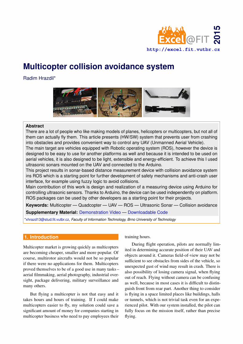
Sensor distribution affects two important param-eters – refresh rate (because of potential disruptions)and weight. I created a sensor beam model (figure2) in Autodesk Autocad to visualize space coveredby sensors and based on the model, I designed sen-sor distribution covering about 90% space around thequadcopter. Author of the quadcopter model is DanielLucena, who published it on GrabCad.com for freeuse2. Model of quadcopter with mounted sensors is
2https://grabcad.com/library/asctec-pelican-quadrotor-1
available in supplementary material.
Figure 2. Quadcopter and sonar beam model forinspecting coverage and finding best sonardistribution.
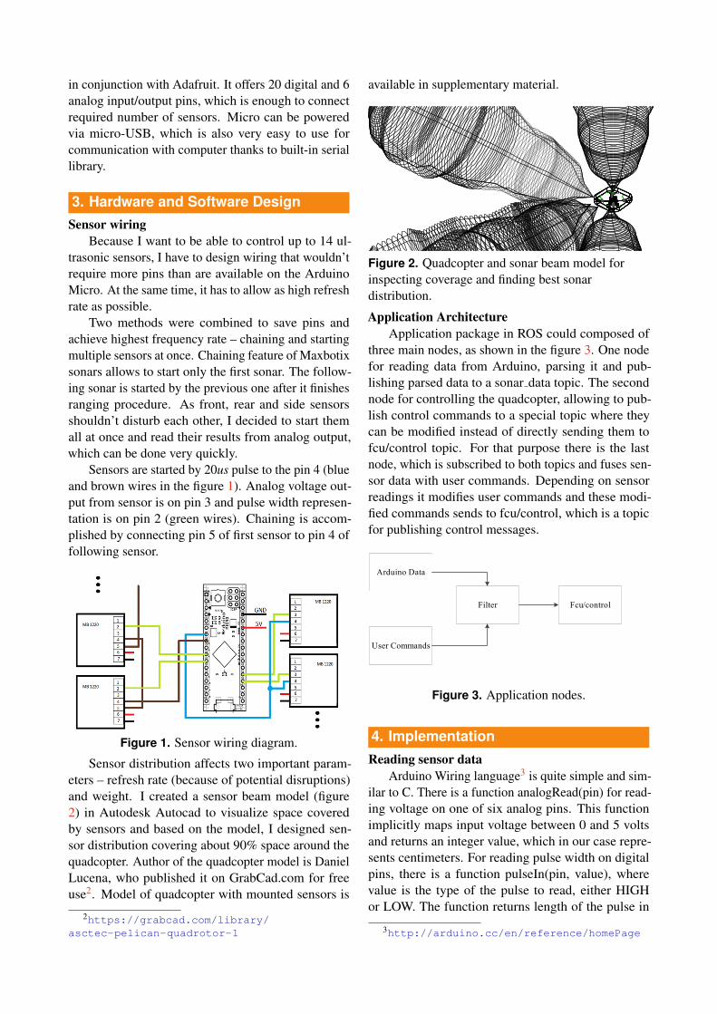
Application ArchitectureApplication package in ROS could composed of
three main nodes, as shown in the figure 3. One nodefor reading data from Arduino, parsing it and pub-lishing parsed data to a sonar data topic. The secondnode for controlling the quadcopter, allowing to pub-lish control commands to a special topic where theycan be modified instead of directly sending them tofcu/control topic. For that purpose there is the lastnode, which is subscribed to both topics and fuses sen-sor data with user commands. Depending on sensorreadings it modifies user commands and these modi-fied commands sends to fcu/control, which is a topicfor publishing control messages.
Arduino Data
Filter
User Commands
Fcu/control
Figure 3. Application nodes.
4. ImplementationReading sensor data
Arduino Wiring language3 is quite simple and sim-ilar to C. There is a function analogRead(pin) for read-ing voltage on one of six analog pins. This functionimplicitly maps input voltage between 0 and 5 voltsand returns an integer value, which in our case repre-sents centimeters. For reading pulse width on digitalpins, there is a function pulseIn(pin, value), wherevalue is the type of the pulse to read, either HIGHor LOW. The function returns length of the pulse in
3http://arduino.cc/en/reference/homePage
Measured distance Digital result Analog result20 25 1950 62 4480 100 71
110 139 98140 178 126170 217 156190 243 174
Table 1. Table of analog and digital measurementsbefore any calibration.
microseconds, so I need to divide the returned valueby 584 to convert it to centimeters.Calibration
After conducting several experiments, it turned outresults obtained by analog and digital readings differvery significantly and neither of them are accurate.A set of 20 measurements was taken by analog anddigital reading and entered into a table. From the table1 is obvious that without any calibration, this systemwould be hardly usable.
Linear error is possible to model by simple linearequation 1, where y is desired correct distance, x ismeasured distance and a, b are real numbers.
y = ax+b (1)
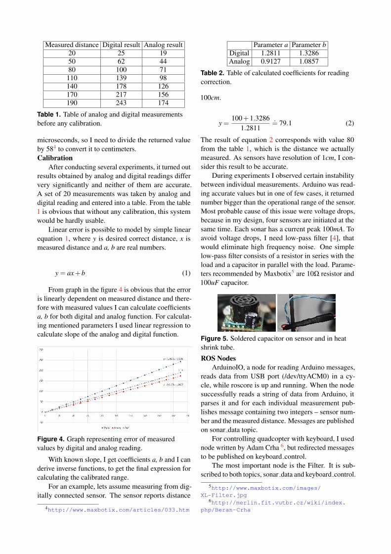
From graph in the figure 4 is obvious that the erroris linearly dependent on measured distance and there-fore with measured values I can calculate coefficientsa, b for both digital and analog function. For calculat-ing mentioned parameters I used linear regression tocalculate slope of the analog and digital function.
Figure 4. Graph representing error of measuredvalues by digital and analog reading.
With known slope, I get coefficients a, b and I canderive inverse functions, to get the final expression forcalculating the calibrated range.
For an example, lets assume measuring from dig-itally connected sensor. The sensor reports distance
4http://www.maxbotix.com/articles/033.htm
Parameter a Parameter bDigital 1.2811 1.3286Analog 0.9127 1.0857
Table 2. Table of calculated coefficients for readingcorrection.
100cm.
y =100+1.3286
1.2811.= 79.1 (2)
The result of equation 2 corresponds with value 80from the table 1, which is the distance we actuallymeasured. As sensors have resolution of 1cm, I con-sider this result to be accurate.
During experiments I observed certain instabilitybetween individual measurements. Arduino was read-ing accurate values but in one of few cases, it returnednumber bigger than the operational range of the sensor.Most probable cause of this issue were voltage drops,because in my design, four sensors are initiated at thesame time. Each sonar has a current peak 100mA. Toavoid voltage drops, I need low-pass filter [4], thatwould eliminate high frequency noise. One simplelow-pass filter consists of a resistor in series with theload and a capacitor in parallel with the load. Parame-ters recommended by Maxbotix5 are 10Ω resistor and100uF capacitor.
Figure 5. Soldered capacitor on sensor and in heatshrink tube.
ROS NodesArduinoIO, a node for reading Arduino messages,
reads data from USB port (/dev/ttyACM0) in a cy-cle, while roscore is up and running. When the nodesuccessfully reads a string of data from Arduino, itparses it and for each individual measurement pub-lishes message containing two integers – sensor num-ber and the measured distance. Messages are publishedon sonar data topic.
For controlling quadcopter with keyboard, I usednode written by Adam Crha 6, but redirected messagesto be published on keyboard control.
The most important node is the Filter. It is sub-scribed to both topics, sonar data and keyboard control.
5http://www.maxbotix.com/images/XL-Filter.jpg
6http://merlin.fit.vutbr.cz/wiki/index.php/Beran-Crha

When a new message comes from sonar data, it up-dates the distance in direction defined by the sonarnumber. Also updates the state of this direction de-pending on the reported distance. When a new mes-sage comes from keyboard control, speed is loweredbased on the state of the desired direction.
5. ConclusionsThis paper described hardware and software designof a measuring device and implementation of an anti-crash package for Robotic operating system.
Designed device can control up to 14 sensors withhigh frequency of measuring. Under good conditions,sensors can measure with deviation 1cm. Achievedcoverage of space around the UAV is about 90%.
The main contribution of this work is design andrealization of a measuring device using Arduino forcontrolling sensors. Thanks to Arduino, the device canbe used independently on platform. I implemented ofan anti-crash package for the most widespread robotprogramming framework nowadays – ROS.
The anti-crash package works independently onthe type of used sensors, so if any other team wantsto start developing with optical type of sensors, theycan use this package as a starting point to speed up thedevelopment.
In the future, I am going to implement advancedcontroller for positioning the UAV utilizing PID con-troller or a fuzzy regulator, which would allow to setparameters like weight or speed for specific model.
Acknowledgements
The author thanks Ing. Vıtezslav Beran, Ph.D. for hissupervision and guidance.
References[1] Sergio Montenegro Nils Gageik, Thilo Muller.
Obstacle detection and collision avoidanceusing ultrasonic distance sensors foranau-tonomous quadrocopter. Technical report,University of Wurzburg, Aerospace Infor-mation Technology(Germany), September2012. [Online; Accessed 03-April-2015].Available at http://www8.informatik.uni-wuerzburg.de/fileadmin/10030800/user_upload/quadcopter/Paper/Gageik_Mueller_Montenegro_2012_OBSTACLE_DETECTION_AND_COLLISION_AVOIDANCE_USING_ULTRASONIC_DISTANCE_SENSORS_FOR_AN_AUTONOMOUS_QUADROCOPTER.pdf.
[2] Bob Gross. Maxsonar operation on a multi-copter. online, February 2013. [Online; Accessed03-April-2015]. Available at http://www.maxbotix.com/articles/067.htm.
[3] Jason M. O’Kane. A Gentle Introductionto ROS. Independently published, October2013. Available at http://www.cse.sc.edu/˜jokane/agitr/.
[4] Wikipedia. Low-pass filter — Wikipedia,the free encyclopedia, 2013. [Online;accessed 01-April-2015]. Available athttp://http://en.wikipedia.org/wiki/Low-pass_filter.