MultiCom Manual 4.0
23
MultiCom for LabVIEW ® for Windows ™
Transcript of MultiCom Manual 4.0

8/3/2019 MultiCom Manual 4.0
http://slidepdf.com/reader/full/multicom-manual-40 1/23
MultiComfor LabVIEW ® for Windows ™

8/3/2019 MultiCom Manual 4.0
http://slidepdf.com/reader/full/multicom-manual-40 2/23
Copyright © 1996, Viewpoint Software Solutions, Inc.
All Rights Reserved

8/3/2019 MultiCom Manual 4.0
http://slidepdf.com/reader/full/multicom-manual-40 3/23
Viewpoint Software Solutions, Inc. does not warrant that the Program will
meet Customer’s requirements or will operate in the combinations which
may be selectedby the Customer or that the operation of the Program will be uninterrupted
or error free or that all Program defects will be corrected.
VIEWPOINT SOFTWARE SOLUTIONS, INC. DOES NOT ANDCANNOT WARRANT THE PERFORMANCE OR RESULTS THAT
MA Y BE OBTAINED BY USING THIS SOFTWARE. ACCORDINGLY,
THE SOFTWARE AND ITS DOCUMENTATION ARE SOLD “A S IS”
WITHOUT WARRANTY AS TO THEIR PERFORMANCE,MERCHA NTABILITY, OR FITNESS FOR ANY PARTICULA R
PURPOSE. THE ENTIRE RISK AS TO THE RESULTS ANDPERFORMANCE OF THE PROGRAM IS ASSUMED BY YOU.
NEITHER VIEWPOINT SOFTWARE SOLUTIONS, INC. NOR ANYONE
ELSE WHO HAS BEEN INVOLVED IN THE CREATION,
PRODUCTION, OR DELIVERY OF THIS SOFTWARE SHALL BE
LIABLE FOR ANY DIRECT, INCIDENTAL, OR CONSEQUENTIAL
DAMAGES, SUCH AS, BUT NOT LIMITED TO, LOSS OFANTICIPATED PROFITS OR BENEFITS, RESULTING FROM THE USE
OF THE PROGRAM OR ARISING OUT OF ANY BREACH OF ANY
WA RRANTY. SOME STA TES DO NOT ALLOW THE EXCLUSION OR
LIMITATION OF DIRECT INCIDENTAL OR CONSEQUENTIAL
DAMAGES, FOR THE ABOVE MAY NOT APPLY TO YOU.
LabVIEW ® is a trademark of National Instruments Inc.
All other brand and product names are trademarks or registered trademarks
of their respective companies.
© Copyright Viewpoint Software Solutions, Inc., 1996.
All Rights Reserved. Reproduction or adaptation of any part of this
documentation beyond that permitted by Section 117 of the 1976 United
States Copyright Act without permission of the Copyright owner is unlawful.
Viewpoint Software Solutions, Inc.
2320 Brighton Townline Road
Rochester, NY 14623-2708

8/3/2019 MultiCom Manual 4.0
http://slidepdf.com/reader/full/multicom-manual-40 4/23
8/3/2019 MultiCom Manual 4.0
http://slidepdf.com/reader/full/multicom-manual-40 5/23
The installed files are described below.
Not e:Not e: If you are installing MultiCom over an older version make sure
that the old A SERIA L.DLL file is removed from your hard disk.
The installation program checks your \ WINDOWS directory for
this file but if an older version is located in other directories,
problems could result.
IntroductionMultiCom is a set of LabVIEW VIs that allow communication with
the Star Gate Technologies Avanstar 100i board. The 100i board
supports either 8 or 16 RS-232 or RS-422 communications ports. Each
port is configurable to support a wide range of baud rates, handshake
modes and other communications parameters.
Installation
MultiCom version 4.0 contains two separate installation programs
located in two separate directories on the installation diskette. The
version in the MCLV16 directory supports LabVIEW versions 3.0, 3.1,and the Windows version of LabVIEW 4.0 (16-bit version). The
version in the MCLV32 directory supports LabVIEW version 4.0 for
Windows 95 (32-bit version).
A setup program is provided to ensure proper software installation. To
run the setup program, perform the following steps:
1. Start Windows and open the Program Manager.
2. Place the MultiCom diskette in a floppy drive.
3. Choose File/Run.
4. Type d :\ MCLVxx \ SETUP where d is the floppy drive letter
(A or B) and xx corresponds to the version of MultiCom that
you want to install (16 or 32). Select OK.
2

8/3/2019 MultiCom Manual 4.0
http://slidepdf.com/reader/full/multicom-manual-40 6/23
\ MCLV40 or copy A100I.CP into your current directory before
you execute A100LOAD.
Not e:Not e: Since A100LOAD only loads code to the board's memory space
(i.e., no portion of A 100LOAD remains resident after execution),
A100LOAD can be executed at anytime before the MultiCom
VIs are used.
Since the Avanstar board uses memory for its buffer space, Windows
and any expanded memory manager such as EMM386 must be
informed so that the Avanstar memory addresses are not overwritten.
In the [386Enh] section of the SYSTEM.INI file in your \ WINDOWS
directory include the line:
EMMExclude=[start segment]-[end segment]
For example, for a board configured to use the 16K block of memory at
D0000h, include the line:
EMMExclude=D000-D3FF
Refer to the documentation for your expanded memory manager to
determine the syntax for excluding memory. Typically, an exclude
parameter will have to be included in the CONFIG.SYS file on the
expanded memory manager device line.
A100I.CP
This fi le is the control program file for the Avanstar board. This fi le is
used by the A100LOAD download program.
4
8/3/2019 MultiCom Manual 4.0
http://slidepdf.com/reader/full/multicom-manual-40 7/23
ASERIAL.DLL
This fi le is the Windows driver file for the Avanstar 100i board for
16-bit platforms. This fi le should be located in the
\ WINDOWS\ SYSTEM directory. The setup program places this file
in the \ WINDOWS\ SYSTEM directory by default .
ASER32.DLLThis fi le is the Windows driver file for the Avanstar 100i board for
32-bit platforms. This fi le should be located in the
\ WINDOWS\ SYSTEM directory. The setup program places this file
in the \ WINDOWS\ SYSTEM directory by default .
PKPK16.DLLPKPK32.DLL
These are utility fi les called by ASER32.DLL and are installed only for
the 32-bit version of MultiCom. These fi les are installed in the same
directory as ASER32.DLL.
README.TXT
This file contains any last minute information not included in this
manual.
SERIAL.LLB
Use this set of VIs if you intend to convert existing VIs that use the
computer’s COM ports to use the Avanstar COM ports. This fi le is
designed to look exactly like the SERIAL.LLB fi le that comes from
National Instruments as a part of LabVIEW. The Mult iCom
SERIA L.LLB contains five VIs:
v Bytes at Serial Port.vi
v Serial Port Break.vi
v
Serial Port Init.vi
5

8/3/2019 MultiCom Manual 4.0
http://slidepdf.com/reader/full/multicom-manual-40 8/23
v Serial Port Write.vi
v Serial Port Read.vi
Note that the names of the VIs are exactly the same as the names of
the VIs in the original SERIAL.LLB. This was done so that an
existing LabVIEW application can be switched over to use the
Avanstar COM ports by simply replacing the original SERIAL.LLB
with the MultiCom SERIA L.LLB. Once the MultiCom SERIA L.LLB
is in place, LabVIEW will automatically use the new VIs instead of the
old ones and therefore will use the Avanstar ports instead of thecomputer’s COM ports. The MultiCom VIs are wired the same as the
LabVIEW serial VIs.
When replacing the original SERIA L.LLB be careful not to overwrite
or delete it. It would be a good idea to rename the original
SERIA L.LLB file before copying the MultiCom version onto your harddisk.
A lso be aware that both the 16-bit and 32-bit versions of MultiCom
install a fi le named SERIAL.LLB. The 16-bit version of SERIA L.LLB
is not compatible with the 32-bit version. If you plan to install both
the 16 and 32 bit versions of MultiCom on the same computer be
careful to rename the files or install the two versions to different
directories.
Once you have replaced the serial VI library, the only noticeable
difference that you will see is on the lower right corner of the icons
will be a small “A” to signify “Avanstar” as shown below.
6

8/3/2019 MultiCom Manual 4.0
http://slidepdf.com/reader/full/multicom-manual-40 9/23
Original icon MultiCom icon
7
8/3/2019 MultiCom Manual 4.0
http://slidepdf.com/reader/full/multicom-manual-40 10/23
SERIALAV.LLB
This library contains 15 VIs. The first five are renamed copies of the
VIs in the SERIA L.LLB. The sixth VI is a special version of the
Avanstar Serial Port Read.vi that include EOS (End-Of-String)
detection and timeout – refer to the section below for information on
this VI. The seventh VI is a special version of Avanstar Serial Port
Init.vi that configures the specified port as an RS-422 port.
v
Avanstar Bytes at Serial Port.viv Avanstar Serial Port Break.vi
v Avanstar Serial Port Init.vi
v Avanstar Serial Port Write.vi
v Avanstar Serial Port Read.vi
v Avanstar Serial Port Read+.vi
v Avanstar Serial 422 Port Init.vi
The last eight VIs were added for MultiCom version 2.0:
v Avanstar Bytes at Output Serial Port.vi
v Avanstar Comm Input Status.vi
v Avanstar CTS/DSR Status.vi
v Avanstar EOS Status.viv Avanstar Max Serial Port.vi
v Avanstar Output Buf Clear.vi
v Avanstar RTS/DTR Control.vi
v Avanstar Serial Port Init+.vi
To configure a port as an RS-232 port use the Serial Port Init VI. Toconfigure for RS-422 use the Avanstar Serial 422 Port Ini t VI. Note
that the two init VIs wire identically. Therefore you can simply
convert a port from 232 to 422 (or vice-versa) by simply replacing the
VI in the wiring diagram.
8

8/3/2019 MultiCom Manual 4.0
http://slidepdf.com/reader/full/multicom-manual-40 11/23
Caut ion:Caut ion: The cable wiring for RS-232 and RS-422 are not
compatible. Be sure that your configuration matches your
hardware setup.
Be aware that both the 16-bit and 32-bit versions of MultiCom install
a file named SERIA LAV.LLB. The 16-bit version of SERIA LAV.LLB
is not compatible with the 32-bit version. If you plan to install both
the 16 and 32 bit versions of MultiCom on the same computer becareful to rename the files or install the two versions to different
directories.
9

8/3/2019 MultiCom Manual 4.0
http://slidepdf.com/reader/full/multicom-manual-40 12/23
MultiCom VIs
The VIs described in this section are the MultiCom VIs that gobeyond the functionality of the serial VIs provided in LabVIEW. For
information on the following VIs:
v Avanstar Bytes at Serial Port.vi
v Avanstar Serial Port Break.vi
v Avanstar Serial Port Init.vi
v Avanstar Serial Port Write.vi
v Avanstar Serial Port Read.vi
v Avanstar Serial 422 Port Init.vi
refer to the documentation on the equivalent VI in the LabVIEW
“GPIB and Serial Port VI Reference Manual.”
Avanstar Bytes at Output Serial Port.vi
This VI returns the number of bytes waiting to be transmitted in the
output buffer. Typically the only time the byte count will be a
non-zero value is if some sort of output handshaking is enabled and the
receiver is holding off the data transmission.
port number is the MultiCom port number(zero-based).
byte count is the number of bytes in the output bufferthat have not been sent.
10

8/3/2019 MultiCom Manual 4.0
http://slidepdf.com/reader/full/multicom-manual-40 13/23
Avanstar EOS Status.vi
This VI checks the input buffer for the specified “end of string”
character. No data is removed or transferred out of the input buffer.
Use this VI to check for an EOS character before the Avanstar Serial
Port Read+.vi is called to eliminate the need for the read operation to
wait for the reception of the EOS character.
port number is the MultiCom port number(zero-based).
EOS character is the ASCII value of the character tobe checked for.
EOS Detected returns a true if the EOS character isdetected in the input buffer.
Avanstar Max Serial Port.vi
Max Port is the value of the largest MultiCom portnumber (zero-based) detected in hardware.
12
8/3/2019 MultiCom Manual 4.0
http://slidepdf.com/reader/full/multicom-manual-40 14/23
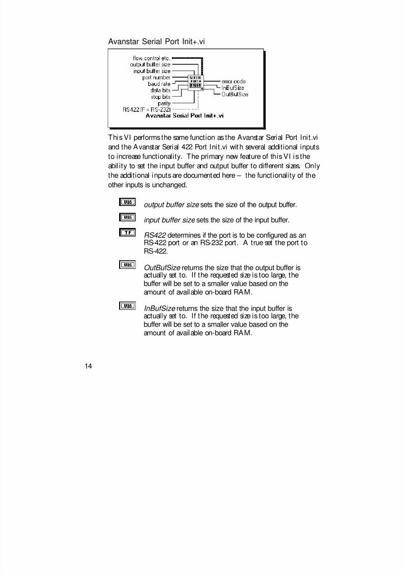
Avanstar Serial Port Init+.vi
This VI performs the same function as the Avanstar Serial Port Init.vi
and the Avanstar Serial 422 Port Init.vi with several additional inputs
to increase functionality. The primary new feature of this VI is the
abil ity to set the input buffer and output buffer to different sizes. Only
the additional inputs are documented here – the functionality of theother inputs is unchanged.
output buffer size sets the size of the output buffer.
input buffer size sets the size of the input buffer.
RS422 determines if the port is to be configured as anRS-422 port or an RS-232 port. A true set the port toRS-422.
OutBufSize returns the size that the output buffer isactually set to. If the requested size is too large, thebuffer will be set to a smaller value based on the
amount of available on-board RAM.
InBufSize returns the size that the input buffer isactually set to. If the requested size is too large, thebuffer will be set to a smaller value based on theamount of available on-board RAM.
14
8/3/2019 MultiCom Manual 4.0
http://slidepdf.com/reader/full/multicom-manual-40 15/23
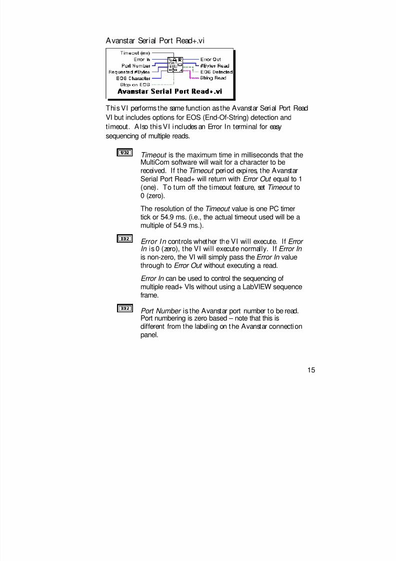
Avanstar Serial Port Read+.vi
This VI performs the same function as the Avanstar Serial Port Read
VI but includes options for EOS (End-Of-String) detection andtimeout. A lso this VI includes an Error In terminal for easy
sequencing of multiple reads.
Timeout is the maximum time in milliseconds that theMultiCom software will wait for a character to be
received. If the Timeout period expires, the AvanstarSerial Port Read+ will return with Error Out equal to 1(one). To turn off the timeout feature, set Timeout to0 (zero).
The resolution of the Timeout value is one PC timertick or 54.9 ms. (i.e., the actual timeout used will be amultiple of 54.9 ms.).
Error In controls whether the VI will execute. If Error In is 0 (zero), the VI will execute normally. If Error In is non-zero, the VI will simply pass the Error In valuethrough to Error Out without executing a read.
Error In can be used to control the sequencing of
multiple read+ VIs without using a LabVIEW sequenceframe.
Port Number is the Avanstar port number to be read.Port numbering is zero based – note that this isdifferent from the labeling on the Avanstar connectionpanel.
15

8/3/2019 MultiCom Manual 4.0
http://slidepdf.com/reader/full/multicom-manual-40 16/23
Requested # Bytes is the maximum number ofcharacters that will be read from the Avanstar port
regardless of whether an EOS is found.
EOS Character is the ASCII code for the characterwhich will cause the serial read to stop (if Stop onEOS is turned on). For example, if a serial devicereturns a string of the form,
+#.####<cr><lf>setting the EOS Character to 10 (a linefeed character)will cause the read to stop after it has received thelinefeed character.
Stop on EOS determines whether the read will searchfor an EOS character. The read will be terminated on
EOS if Stop on EOS is true.
Error Out is the error value returned by the readfunction. If Error Out is a 1 (one), a timeout occurred.If Error Out is a negative number, a board level erroroccurred.
#Bytes Read is the length of the String Read.
EOS Detected shows whether the read stopped becauseof an EOS detection.
String Read is the data received from the Avanstarport.
16

8/3/2019 MultiCom Manual 4.0
http://slidepdf.com/reader/full/multicom-manual-40 17/23
General Information
Understanding the Avanstar hardware
Much of the job of sending and receiving data is taken care of by the
Avanstar board. The Avanstar board contains an individual UART
for each channel and an on-board microprocessor to handle data traffic
between the UARTs and your PC/LabVIEW. Each UART is a circuit
designed to send and receive serial data and contains two 12 byte FIFO(First In, First Out) buffers – one for sending and one for receiving
data. The board’s processor monitors all data channels and transfers
data between the UART’s FIFOs and the board’s buffer area. The
MultiCom VIs send/receive data by transferring data to/from the
Avanstar buffers. See figure below.
UART
Input data
Outputdata
On-board Processor
Avanstar buffers
MultiCom VIs
Stop Bit Support
The Avanstar board supports either 1 or 2 stop bits; the 1.5 stop bits
option is not available. To configure a port for 1 stop bit, pass a 0
(zero) to the stop bits parameter in the init VI. To select 2 stop bits,
pass a 2 to the init VI.
17

8/3/2019 MultiCom Manual 4.0
http://slidepdf.com/reader/full/multicom-manual-40 18/23
Port Numbering
In order to remain compatible and consistent with LabVIEW, theMultiCom VIs use a zero based numbering scheme, (i.e., the first port
is number zero). Note that this confl icts with the numbering on the
Avanstar terminal panel which is one based.
If multiple boards are used, the ports will be numbered according to the
I/O address the board is found at. For example, if two 16 port boards
are used and have I/O addresses of 200h and 208h, then the ports
would be numbered as follows:
16-31208h
0-15200h
Port Numbers I/O Address
Additional Baud Rates
The MultiCom VIs allow you to specify much higher baud rates than
the original VIs do. In order to accommodate these higher baud rates,
the Baud Rate control in the Serial Port Init VI was changed from a
U16 data type to a U32 data type. The following baud rates are
supported under MultiCom.
56,0002,400200
38,4001,800150115,20019,2001,200134.5
76,8009,6001,050110
64,0007,20060075
57,6004,80030050
The Avanstar board has an option for 134.5 baud rate. To select this
rate, pass the value 134 to the init baud rate terminal.
18

8/3/2019 MultiCom Manual 4.0
http://slidepdf.com/reader/full/multicom-manual-40 19/23
Handshaking Modes
All of the handshaking modes featured in the original LabVIEW VIsare supported by MultiCom except “Output alt HW Handshake.” If
you need output hardware handshaking you may have to convert your
application to use the CTS line and “Output HW Handshake” mode.
Buffer Sizes
The Avanstar 100i board contains 16K of memory. This memory is
used for board control registers as well as for input and output buffers.
Out of the 16 Kbytes, 15,328 bytes is available for buffers.
The default buffer size is 464 bytes for the 16 port board (i.e. 464 bytes
for the input buffer and another 464 bytes for the output buffer for
each port .). The minimum buffer size is 2 bytes. The maximum buffersize is only limited by the amount of free space available; therefore to
allocate a large buffer for a particular port, it is necessary to reduce the
size of the some of the other port buffers.
The init VI default for buffer size is 0 (zero). The effect of this (or any
value less than 2) is to leave the buffer size unaltered from its currentvalue. Therefore leaving the buffer size terminal unwired on any of the
MultiCom init VIs will not change the buffer size.
Not e:Not e: The original Serial Port Init VI will default the input and
output buffer sizes to 1024 bytes if the buffer size terminal is left
unwired. Keep this difference in mind if you replace an original
VI with one of the MultiCom init VIs; the operation of your
application may be affected.
Caut ion:Caut ion: Do not change the size of any MultiCom buffer while any
port is active. Changing buffer sizes moves the locations of the
buffers of many MultiCom ports and could result in lost data.
19

8/3/2019 MultiCom Manual 4.0
http://slidepdf.com/reader/full/multicom-manual-40 20/23
Reads/Writes May Hang LabVIEW
The MultiCom software is not interrupt driven and therefore onceLabVIEW enters the MultiCom code, no Windows (LabVIEW or
otherwise) can occur. Consequently, if you request more characters to
be read than have been transmitted, the computer will wait
indefinitely until the requested number of characters are read (unless a
timeout is specified or an EOS character is detected). Likewise, if a
write is held off due to a handshake situation, the computer will waitindefinitely until the hold off condition is released. To avoid this
problem it is important to follow these guidelines:
Readsv Use the Bytes at Serial Port VI to determine the number of bytes
that can be read. The proper use of this VI will also increase the
execution efficiency of your code since no time will be spent in
the MultiCom software waiting to data to be received.
v Use the Avanstar Serial Port Read+ VI with timeout enabled to
prevent LabVIEW from hanging if no data is available.
Writes
v Use the Bytes at Output Port VI to determine if there is room inthe output buffer for the new output string. The proper use of
this VI will also increase the execution efficiency of your code
since no time will be spent in the MultiCom software waiting
for the output buffer to empty.
v Be careful when using handshaking to ensure a proper setup with
the external device.
If LabVIEW hangs in one of these wait loops, press
<Ctrl><Alt><Del> followed by <Enter> to shut down LabVIEW and
return to Windows.
20

8/3/2019 MultiCom Manual 4.0
http://slidepdf.com/reader/full/multicom-manual-40 21/23
Serial Port Break VI
The break generated by the Avanstar board is a fixed time length.A lthough the MultiCom Serial Port Break VI includes a delay terminal
for compatibility with the original LabVIEW VI, the value passed is
ignored by the Avanstar board.
PCI Bus Computers
If you encounter problems installing/running MultiCom on a PCI bus
computer, check your computer's PCI bus configuration. On PCI bus
computers the PCI controller controls the ISA bus's access to memory.
This memory access is set in the machine's BIOS configuration. The
memory that the MultiCom board uses must be accessible to the ISA
bus. Check your BIOS configuration program to be sure that the PCI
controller allows access to the memory that you will be using for your
MultiCom board.
Parity Error Byte in the Flow Control Cluster
If the high-order byte of the Parity Error Byte field in the Flow Control
cluster in the serial initialization routines is non-zero, MultiCom willinsert an FFh into the input buffer (not the low order byte of the
Parity Error Byte field as in LabVIEW) when a parity error is detected.
The low-order byte of the Parity Error Byte field is not used by
MultiCom.
21
8/3/2019 MultiCom Manual 4.0
http://slidepdf.com/reader/full/multicom-manual-40 22/23
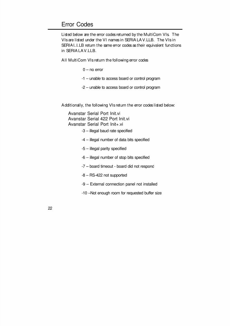
Error Codes
Listed below are the error codes returned by the MultiCom VIs. TheVIs are listed under the VI names in SERIA LAV.LLB. The VIs in
SERIAL.LLB return the same error codes as their equivalent functions
in SERIA LAV.LLB.
All MultiCom VIs return the following error codes
0 – no error
-1 – unable to access board or control program
-2 – unable to access board or control program
Additionally, the following VIs return the error codes listed below:
Avanstar Serial Port Init.viAvanstar Serial 422 Port Init.viAvanstar Serial Port Init+.vi
-3 – illegal baud rate specified
-4 – illegal number of data bits specified
-5 – illegal parity specified
-6 – illegal number of stop bits specified
-7 – board timeout - board did not respond
-8 – RS-422 not supported
-9 – External connection panel not installed
-10 –Not enough room for requested buffer size
22

8/3/2019 MultiCom Manual 4.0
http://slidepdf.com/reader/full/multicom-manual-40 23/23
Avanstar Serial Port Read+.vi
1 – timeout exceeded
How to Reach Us
Viewpoint Software Solutions, Inc.
2320 Brighton Townline Road
Rochester, NY 14623-2708
phone: (716) 475-9555
fax: (716) 475-9645
e-mail: [email protected]
Technical support is available by e-mail , fax or voice. Phone support
is available business days, 9:00 a.m. to 5:00 p.m. Eastern time.
Before calling for technical support please double check your work.
When calling, it is important to have all relevant information on
hand.
23