Multicasting with Physical Layer Constraints in Metropolitan
40
Multicasting with Physical Layer Constraints in Metropolitan Optical Networks with Mesh Topologies Tania Panayiotou KIOS Research Center for Intelligent Systems and Networks KIOS Research Center for Intelligent Systems and Networks Dept. Electrical and Computer Engineering University of Cyprus 16 th February 2011 Acknowledgement: This work is supported by the Cyprus Research Promotion Foundation and the EU Structural Funds under Grant PENEK/ENISX/0308
Transcript of Multicasting with Physical Layer Constraints in Metropolitan

Multicasting with Physical LayerConstraints in MetropolitanOptical Networks with MeshTopologies
Tania Panayiotou
KIOS Research Center for Intelligent Systems and NetworksKIOS Research Center for Intelligent Systems and NetworksDept. Electrical and Computer Engineering
University of Cyprus
16th February 2011
Acknowledgement: This work is supported by the Cyprus Research PromotionFoundation and the EU Structural Funds under Grant PENEK/ENISX/0308

Outline
• IntroductionIntroduction
• Physical Layer Impairments• Physical Layer Impairments
• Multicasting in Transparent Networks• Multicasting in Transparent Networks
M lti t P t ti• Multicast Protection
C l i d F t W k• Conclusions and Future Work

Introduction-Optical Networksp
• Optical Network:p• Telecommunications network with transmission links that are
optical fibers, “intelligent” optical switching nodes, and with anarchitecture that is designed to exploit the unique features offibfibers.
• Advantages of Optical fibers:g p• Huge bandwidth capability (e.g., 25 THz)• Low attenuation loss,• Extremely low bit-error rates,Extremely low bit error rates,• Low cost,• Light weight,• Strength and flexibilityStrength and flexibility,• Immunity to noise and electromagnetic interference• Security and privacy

Introduction-Evolution of Optical Networksp
• Point-to-point Networks:p• Fiber transmission links were used as a direct substitute for copper, with
the fibers terminating on electronic equipment.• Due to electornic equipment only a small fraction of the potentially
available bandwidth could be used.
• WDM Networks:• WDM Networks:• The capacity of a fiber link is dramatically increased.• A number of wavelengths is multiplexed for simultaneous transmission
within the same fiberwithin the same fiber.
1λ1λMUX DMUX
Nλλλ ,...,, 21Nλ Nλ

Introduction-Optical Networksp
• Optical Network:p• Telecommunications network with transmission links that are
optical fibers, “intelligent” optical switching nodes, and with anarchitecture that is designed to exploit the unique features offibfibers.
• WDM Optical Network:p• The capacity of a fiber link is dramatically increased.• A number of wavelengths is multiplexed for simultaneous
transmission within the same fiber.transmission within the same fiber.
1λ1λMUX DMUX
Nλλλ ,...,, 21Nλ Nλ

Introduction-Evolution of Optical Networksp
• A typical WDM network cable contains:• More than 100 fibers which are used as bidirectional pairs.• Each fiber can utilize 32 to 64 wavelengths of 0.8 nm spacing covering arange of 1260 - 1675 nm• Each wavelength transmits at rates of 10 Gbps.Each wavelength transmits at rates of 10 Gbps.
• A denser WDM network:• 80 to 160 wavelengths per fiber• Each wavelength transmits at rates of 40 or 100 Gbps• Future DWDM networks expected to increase to 320 wavelengths per fiber.

Introduction-Evolution of Optical Networksp
a. Opaque Network:• All switching and processing of the data is handled by electronic switch fabrics.All switching and processing of the data is handled by electronic switch fabrics.• The optical signal carrying traffic undergoes an optical-electronic-optical (OEO)
conversion at every switching node.
Adq Ads• Offers full digital regeneration of the signal (re-shape, re-time, re-amplify).• Any incoming stream can be switched to any available wavelength on any fiber.• There is no need for end-to-end traffic engineering.
OEO
OEO
g g• The control and management of the network is easy.
q Cons• Limitations in signal bit rate due to electronics
OEO O
E
OEO
OEO
OE
O• Limitations in signal bit rate due to electronics.• Costly network elements.• Bit rate/protocol/modulation format are not transparent.
EO
EO
WDM LinkElectronic Node

Introduction-Evolution of Optical Networksp
b. Transparent Network:p• Switching and processing of the data is moved to the optical part of the networkq Ads• Eliminates the expensive O-E-O conversions.p• Signal is transparent to bit rate, signal format, and protocols.• Provides high bit rates.
q Cons• Physical layer impairments (e.g. noise, dispersion, crosstalk) limit the
transmission reach of optical signals.g• End-to-end engineering of the traffic is required.• Difficult control and management functions.
Optical Node WDM Link

Introduction-Transparent MANsp
• Metropolitan Area Network
Long-haul
(MAN)• Spans a metropolitan area,
typically tens to a few hundred kilometerskilometers.
• Signal attenuation could be overcome using optical amplifiers, as needed.Th i th t th lifi
Metropolitan• The noise that these amplifiers
introduce can be managed due to the relatively short distances, (short amplifier
)Access
spans).• No dispersion issues due to
short fiber lengths• High optical signal to noise
Users
High optical signal to noise ratio can be preserved.
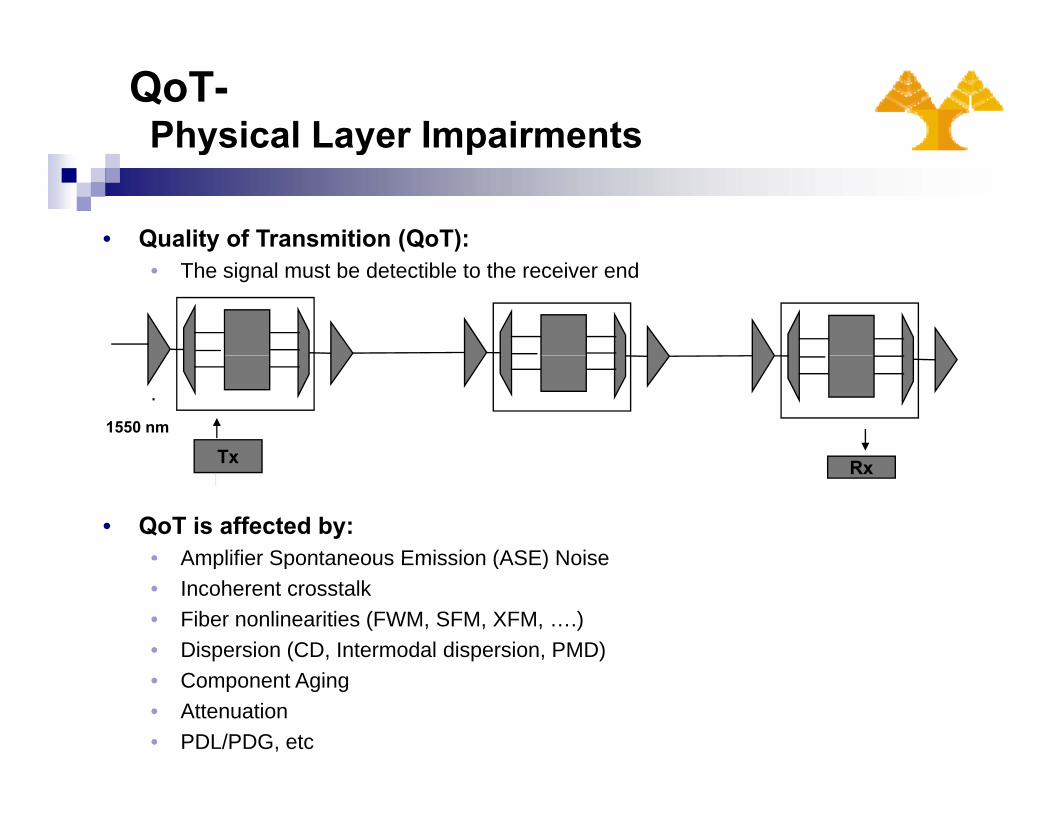
QoT-Physical Layer Impairmentsy y p
• Quality of Transmition (QoT):• The signal must be detectible to the receiver end
1550 nm
Tx
.
RxTx
• QoT is affected by:• Amplifier Spontaneous Emission (ASE) NoiseAmplifier Spontaneous Emission (ASE) Noise• Incoherent crosstalk • Fiber nonlinearities (FWM, SFM, XFM, ….)• Dispersion (CD, Intermodal dispersion, PMD)• Component Aging• Attenuation • PDL/PDG, etc

QoT-Physical Layer System Modelingy y y g
•Physical Layer Impairments must be taken into account during the provisioningh f tphase of request.
•Modeling of the physical layer is based on the physical path Q factor that is usedto calculate the BER of the system.
2222222
,where+−
=σσ 01
01 IIQ
•This approach assumes a baseline system with various receiver noise terms aswell as ASE noise
2222222shotASEiRINiASEsASEASEishotthi −−−−−− +++++= σσσσσσσ
well as ASE noise.•A Q-budgeting approach is used to include:
• Incoherent crosstalk channel penalty budgeted at 0.8dBQ.• Fiber nonlinearities factored at 1 dBQ.• PMD budgeted at 0.2 dBQ.•Optical filter narrowing penalty budgeted at 0.4 dBQ.• Safety margin of 1dBQ included for component aging

QoT-Physical Layer System Modelingy y y g
•This approach enables a network designer to calculate the impact ofphysical layer effects in the design of an optical network without thephysical layer effects, in the design of an optical network without thecomputationally complex time-domain approach.
•A Q threshold is set for a specified BER and the decision to provision a•A Q threshold is set for a specified BER and the decision to provision agiven multicast connection relies on whether we are above or below thethreshold.
Q−
⎞⎛π222
1 2
QQerfcBER e≈⎟
⎠
⎞⎜⎝
⎛=
• Q threshold set at 8.5 dBQ which corresponds to a BER of 10-12

Multicasting-IntroductionIntroduction
•Multicast Applications: interactive distance learning, video-conferencing,distributed games, movie broadcasts from studios, etc.
•Multicast connection:One to many connectivity•One-to-many connectivity
•Light from one source must reach many destinations.•In transparent optical networks optical splitters must be used inside thenodes to split the incoming signal to multiple output ports.p g g p p p
s
m dm
n
d2
d1
Light-tree
d3

Multicast Capable Architectures
MUXDMUXSplitting/Attenuation
Capability
MC-OXCPRE-AMPS POST-AMPS
λ1, λ2..λnλ1, λ2..λn
.
.
.
Add Drop
.
• (MxM) transparent node supporting n wavelengths:• The splitter equally splits the optical signal into M parts, where M is the number of outgoing
(as well as incoming) ports.• PO t = 1/M PiPOut 1/M Pin.• Amplifiers are required to re-amplify the signal.• ASE noise is added to the signal
• These power considerations along with other physical layer impairments must bet k i t t ttaken into account to:
• The design and engineering of transparent optical nodes.• The multicast routing algorithms.

Multicast Capable Architectures
• Several Multicast Capable Mx1 fiber it h1X(M+1) DMUX MUX
Node architectures andEngineering Designs wereinvestigated to determine theimpact of the physical layer :
switch( )splitterDMUX MUX
Nλλλ ,...,, 21
1λ
Nλ
2λ
1..
.
...
.
. . .
1λ
impact of the physical layer :a. Fixed Txs/Rxsb. Tunable Txs/Rxs c. Tunable Txs/ Fixed Rxs Nλλλ ,...,, 21
1λ
2λ
.
.
.
.
.
.
.
gatesVOA
.
.
.
.
.
.
.
.
.
.
.
.
.
.
.
...
d. Fixed Txs /Tunable RxsPOST-AMPPRE-AMP
Nλ
2λ
M .. .
.
. .
• Component Insertion LossComponent Insertion Loss
Component Mux/Dmux VOA Splitter SOA Switch
Losses in dB 3 0.5 10*log(fan out) 0.6 1

Multicast Capable Architectures
• Worst case scenario :• The maximum insertion loss a
signal encounters passing throughthe maximum degree node.
Gain in dB NF
G<13 7
13<G<15 6.7
15<G<17 6 5• Components:
• Amplifiers (EDFAs):• Post-Amplifiers: Compensate
for the node losses and their
15<G<17 6.5
17<G<20 6
G>20 5.5
for the node losses and theirgain is set for the worst casescenario with an output powerof +7dBm.
• Pre-Amplifiers: Preceding the
•Variable OpticalAttenuators (VOAs):Required to equalize thep g
fiber span to compensate forthe fiber losses that are set at0.3dB/Km. Output power is+7dBm.N i Fi b d
Required to equalize theindividual total input powers tothe post amplifiers and signalsare attenuated for the worstcase scenario• Noise Figures are based on
realistic device specifications.case scenario.

Multicast Capable Architectures
a b
• Node Architectures:a. Fixed Tx/Rx : The number of transmitters/receivers for each source/destination node
is equal to the number of wavelengths times the degree of the node.
b. Tunable Tx/Rx :The number of transmitters/receivers for each source/destinationnode is equal to the number of wavelengths.

Multicast Capable Architectures
• Tunable Tx/Rx case: • Switches added at the Tx/Rx can add/drop 50% of the total number
of wavelengths in the network.• The size of the switches is proportional to the number of wavelengths
and the fan-out of the node.• Insertion loss of switches depends on their size.
Size Switches Losses in dB
X<25 1
25<X<36 1 525<X<36 1.5
36<X<56 2.2
56<X<68 3
68<X<80 3.7
80<X<100 4.5
X>100 5

Multicast Routing Algorithms
Several multicast routing algorithms are used for the simulations.1 Minimum Steiner tree heuristic (MST):1. Minimum Steiner tree heuristic (MST):
• Finds the minimum cost tree.• The Steiner tree problem is NP-complete when the multicast group has
more than two members.S l h i ti h b d l d f th St i t bl• Several heuristics have been developed for the Steiner tree problem.
2. Optimized Shortest Paths Tree (OSPT):• Aims at decreasing the number of the links utilized by the tree.
Step 1 For every destination node of the multicast session, repeat Steps 2 and 3
Step 2 Find the minimum-cost path from source to the destination node.Step 3 Update cost = 0 for all the links included in the already-found pathStep 3 Update cost = 0 for all the links included in the already-found path.Step 4 Merge all the minimum-cost paths together and construct a multicast tree.

Multicast Routing Algorithms
3. Balanced Light-Tree (BLT):3. Balanced Light Tree (BLT):• Takes power budget constraints into consideration.• Aims at minimizing the average splitting losses of the tree.• Balancing procedure:Balancing procedure:
node v
Min. splittingLoss Node v
kLoss Node v
Max Splitting LossNode u
node u

Multicast Routing Algorithms
Several multicast routing algorithms are used for the simulations.
Multicast RoutingAlgorithms
Cost Power Budget Constraints
Physical LayerImpairments
Minimum Steiner Optimized Shortest Balanced Light Balanced Light Balanced LightMinimum SteinerTree (MST)
Optimized ShortestPaths Tree (OSPT)
Balanced LightTree (BLT)
Balanced LightTree_Q (BLT_Q)
gTree Q_tolerance
(BLT_Q_tolerance)

Multicast Routing Algorithms
BLT_Q : Aims at maximizing the average Q-value of the tree._ g gBalancing procedure:
node v
Max Q node v
node v
k
Min Qnode u node u
BLT Qtolerance: improves on the BLT Q by maximizing the QBLT_Qtolerance: improves on the BLT_Q by maximizing the Q-factor only at those destination nodes that the Q value below theQtolerance value.

Multicast Routing Algorithms
• The balancing part of the algorithm terminates when twosuccessive iterations fail to increase the minimum Q-factor.
• Tends to create shallower trees increasing the Q-value at thedestination nodes and increasing the total number of the links inthe treethe tree.
BLT Qtolerance:_ tolerance• Aims at maximizing the average Q-value of the tree but keeping
the total number of the links in the tree as low as possible.• Considering that the tolerance Q-factor is k, this algorithmg , g
maximizes the Q-factor only at those destination nodes that theQ-factor is below k.
• Terminates if the Q-value of all destination nodes in the tree isb k if t i it ti f il t i thabove k, or if two successive iterations fail to increase the
minimum Q-factor.
Simulation Parameters
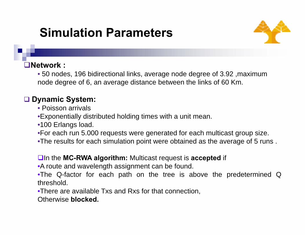
Network :• 50 nodes 196 bidirectional links average node degree of 3 92 maximum• 50 nodes, 196 bidirectional links, average node degree of 3.92 ,maximum node degree of 6, an average distance between the links of 60 Km.
Dynamic System:y y• Poisson arrivals•Exponentially distributed holding times with a unit mean.•100 Erlangs load.•For each run 5 000 requests were generated for each multicast group size•For each run 5.000 requests were generated for each multicast group size.•The results for each simulation point were obtained as the average of 5 runs .
In the MC-RWA algorithm: Multicast request is accepted if•A route and wavelength assignment can be found.•The Q-factor for each path on the tree is above the predetermined Qthreshold.•There are available Txs and Rxs for that connection•There are available Txs and Rxs for that connection,Otherwise blocked.

Simulation Parameters
• To determine the Q-value for each multicast call, a baseline systemQ-value is first calculated based on the signal and noise terms,assuming:• 10 Gbps bit rate
a pre amplified photodiode• a pre-amplified photodiode• 32 wavelengths in each fiber spaced at 100 GHz.• +5dBm power launched into the system .
• To include other common physical layer impairments a Q-budgetingapproach is used that starts from the Q-value for the baselinesystem and budgets Q-penalties for the various physical layerimpairments present.
• Each Q-penalty is calculated as the Q (in dB) without thei i t i l i th Q (i dB) ith th i i t timpairment in place minus the Q (in dB) with the impairment present.

Impairment Aware - MC-RWA Algorithm
• For each multicast connection request, the algorithm first solves the q gmulticast routing problem and then assigns a wavelength for that tree (first-fit algorithm).
• Blocked: There is no available wavelength for the entire tree.
• Accepted:A ro te and a elength assignment can be fo nd• A route and wavelength assignment can be found.
• The Q-factor for each path on the tree is above the predetermined Q threshold.
• There are available Txs and Rxs for that connection• There are available Txs and Rxs for that connection• If the physical impairments constraints are not met, a new
wavelength assignment is implemented and the heuristic is repeated until no new wavelength assignment is possiblerepeated until no new wavelength assignment is possible.

Simulation Results
0 08
Tunable Txs/RxsFixed Txs/Rxs
0 05
0,060,07
0,08
ng
STBLT 0,14
0,160,180,2
ng
STBLTBLT Q 8 5
0,02
0,030,04
0,05
Prbl
ocki BLT_Q_8.5
OSPT
0,060,080,1
0,12
Prbl
ocki
n BLT_Q_8.5OSPT
0
0,01,
4 7 10 13 16 19 22 250
0,020,04
4 7 10 13 16 19 22 25multicast group size multicast group size
•BLT_Q8.5 that takes the PLIs into account performs the best compared to the otherlti t ti l ith f b thmulticast routing algorithms for both cases,
•Pr. Blocking in tunable case is increased compared to the fixed case, since in fixedTxs/Rxs case a larger number of Txs/Rxs is used.

Multicast Protection
• It is important that the multicast traffic is not only routed efficientlyth h th ti l t k b t it i t t d i t iblthrough the optical network but it is protected against any possiblefailures in the network.
• Fiber cuts occur often and are the predominant form of failure.Fiber cuts occur often and are the predominant form of failure.
d1Backup path
sourced2
A fiber cut (link failure) may jeopardize the entire multicast session
d3
• A fiber cut (link failure) may jeopardize the entire multicast session
Multicast Protection
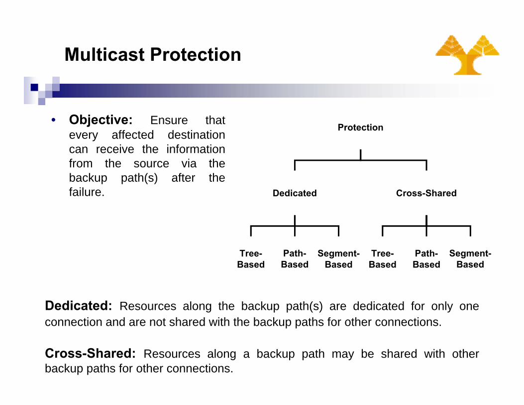
• Objective: Ensure that Protectionjevery affected destinationcan receive the informationfrom the source via thebackup path(s) after the
Protection
backup path(s) after thefailure. Dedicated Cross-Shared
Tree-Based
Path-Based
Segment-Based
Tree-Based
Path-Based
Segment-Based
Dedicated: Resources along the backup path(s) are dedicated for only oneconnection and are not shared with the backup paths for other connections.
Cross-Shared: Resources along a backup path may be shared with otherbackup paths for other connections.

Multicast Protection-Tree-based
Link-Disjoint: Arc-Disjoint:j1. A primary tree.2. A link-disjoint backup tree.
1. A directed primary tree.2. A directed arc-disjoint backup
tree
d
1
d
1
d1
1
d1
1
Redundant capacity reaches the 100 %.
d1
1
11
2
d1
1
1
d1
1
11
2
d1
1
1
s d2
1 12
2
s d2
1
s d2
1 12
2
s d2
1
d32
1
d3
1
d32
1
d3
1

Multicast Protection-Path-based
1. Find primary Light-tree.2. Divides primary tree into several paths according to the destination nodes.3. For each path a minimum cost path from the source to the destination
node is computed, that is arc-disjoint from its primary path.
11
1. {s – d1}2. {s – d2}3. {s – d3}
Self-Sharing: Backuppaths can share theprimary arcs on theprimary tree as long as
d1
1
11
2
d1
1
1
{ 3} primary tree, as long asthere are path arc-disjoint.
s d2 d3
1
1
1
2
s d2
1
2
1 1
1
21
1

Multicast Protection-Segment-basedg
1. Find primary light-tree.p y g2. Divide primary light-tree to un-overlapped segments according to
the segment points of the tree.3. Find the backup paths for each segment .3. Find the backup paths for each segment .
• Definitions:• Segment : A path between two segment points• Segment : A path between two segment points.• Segment points : Splitting nodes, source and destination nodes.

Multicast routing and protection algorithmsg
{s ->m}{ }{m ->n}{n ->d3}{n > d2}
s
{n -> d2}{m ->d1} m d2
nd1 •Each segment is protectedby finding the minimum cost
d3
by finding the minimum costpath between the segmentpoints of each segment.• The backup paths must be
farc-disjoint from theirprimary segments.

Multicast Protection-Segment-based
{s ->m}Sister Node First Algorithm(SSNF)
s{m ->n,d1}
{n ->d3,d2}
(SSNF)• Differs from the conventional SP
in the way the segments areidentifiedD fi i i
m d2
• Definitions:• Sister Nodes: Nodes with a
common parent in the tree.• segment points and m 2segments are as previously
defined.
• The first segment is protected as inth ti l
nd1
the conventional case.• The next segments are protected by
computing the minimum cost treesthat start from the splitting nodes ofeach segment and span the sister
d3
each segment and span the sisternodes in the sets.

Multicast Protection-Segment-based
Level Protection Algorithm (LPA)g ( )• Differs from other segment based schemes in the way the segments
are identified
Divides the primary light-tree into un-overlapped segments basedon the levels of the tree and finds backup paths for each Levelsegment.
Definitions:Segment: a path between two segmentation nodes in the tree.Segmentation node: source node and destination nodes.Level(i) of a segmentation node: the number of the segmentsbetween that segmentation node and the source.Level (i-1, i) segment: is the set of all the segments of the treethat are between level (i-1) and level (i) segmentation nodes.

Multicast Protection-Segment-based (LPA)
s s Level 0
d1
u
d3
y
d2
d1 Level 1
Level 2
d2 d4
d3
d5d4 Level 3
d5d3
Level 4
Segmentation nodes, levelsand level segments areidentified

Multicast Protection-Segment-based (LPA)
•Backup path: A minimum cost tree
s
L(0 1)L(1,2)
L(2,3)
L(3,4)
p pthat starts from any segmentationnode in lower levels, and spans everysegmentation node in the currentlevel.
u y
L(0,1)
L(2,3)L(3,4)
•Example: if we want to protect thesegmentation nodes in level 2, a
i i t t i t d th td1
d2 d4
d3 L(0,1)
L(0,1)
L(0,1)
L(1,2)
L(3,4) minimum cost tree is computed thatstarts from any segmentation node inlevels 0 or 1, and spans everysegmentation node in level 2.
d5
L(1,2)
L(2,3)
•Constrain: The backup tree, must bearc disjoint from its primary levelsegment and from every levelsegment and from every levelsegment that lies between higherlevels.
Simulation Parameters
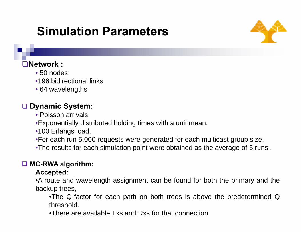
Network :• 50 nodes• 50 nodes•196 bidirectional links• 64 wavelengths
Dynamic System:• Poisson arrivals•Exponentially distributed holding times with a unit mean.•100 Erlangs load•100 Erlangs load. •For each run 5.000 requests were generated for each multicast group size.•The results for each simulation point were obtained as the average of 5 runs .
MC-RWA algorithm:Accepted:•A route and wavelength assignment can be found for both the primary and thebackup treesbackup trees,
•The Q-factor for each path on both trees is above the predetermined Qthreshold.•There are available Txs and Rxs for that connection.

Simulation Results
0 5
Cross- sharing
0 3
Dedicated
0 30,350,4
0,450,5
ing CSP
SSNF 0,2
0,25
0,3
king
CSPSSNF
0,10,150,2
0,250,3
Pr.
bloc
k
LPA
0,05
0,1
0,15
Prbl
ock
LPA
00,05
4 7 10 13 16 19 22 25 28
multicast group size
0
0,05
4 7 10 13 16 19 22 25 28
multicast group sizeg p
•Assumptions: Fixed Txs/Rxs, Q threshold = 8.5 dBQ•LPA performs the best in both cases compared to the other segment based protection
l ith
g p
algorithms.•Cross-Sharing significantly improves the network performance.

Conclusions and Future Work
Conclusions:Conclusions:•Different node architectures and engineering designs produce differentmulticast group blocking, a strong indicator that a better interactionbetween physical and logical layers is needed for multicast connectionbetween physical and logical layers is needed for multicast connectionprovisioning.
Future Work:•Our current work focuses on further accounting and determining theimpact of PDG and PDL on the algorithms and the system performance.• Future work focuses to the provisioning and protection of groupcastrequests when PLIs are taken into account.•Additional work has been done on unicast connections taking intoaccount the PLIs.Additi l k h b d i b t ti f•Additional work has been done on grooming subrate connections for
multicast applications (grooming for groupcast applications is scheduledas future work).