Multicast Virtual Private Networks - M.S. in...
56
Graduate Program in Telecommunications George Mason University Technical Report Series 4400 University Drive MS#2B5 Fairfax, VA 22030-4444 USA http://telecom.gmu.edu/ 703-993-3810 Multicast Virtual Private Networks CHRISTOPHER LENART [email protected] Technical Report GMU-TCOM-TR-09
-
Upload
phungxuyen -
Category
Documents
-
view
220 -
download
0
Transcript of Multicast Virtual Private Networks - M.S. in...
Graduate Program in Telecommunications
George Mason University Technical Report Series
4400 University Drive MS#2B5
Fairfax, VA 22030-4444 USA
http://telecom.gmu.edu/
703-993-3810
Multicast Virtual Private Networks
CHRISTOPHER [email protected]
Technical Report GMU-TCOM-TR-09

Abstract
Multicast has long been a popular technology in computer networks for the e�cient distribution of data, such as patchesor live video, to multiple users simultaneously. The early implementations were always restricted to a single network, anda remote o�ce would need its own multicast distribution system separate from a main o�ce, for example. This reportdescribes Next-Generation Multicast Virtual Private Networks (NG-MVPN). NG-MVPN is a popular technology used byservice providers to connect the multicast networks for several locations over their network. The beginning of this reportstarts by describing the building blocks of NG-MVPN. These are Multicast, Multiprotocol Label Switching (MPLS),Border Gateway Protocol (BGP) and BGP/MPLS VPNs. The report assumes the reader already has an understandingof these technologies. For brevity, the essential parts of these technologies required for NG-MVPN are discussed. Theservice provider multicast technology, MVPN (mVPN), written by Eric Rosen and also called Draft Rosen MVPN alsois discussed as background. Lastly, this report also discusses Global Table Multicast (GTM), which is an extension ofNG-MVPN that uses the global routing table rather than the segregated routing tables used for BGP Virtual PrivateNetworks. Resources for this report are mainly IETF Request for Comments, but also includes technical books, technicalarticles, and personal communication. All references are be cited and listed at the end of the report.

Contents
Introduction i
1 Building Blocks: Multicast, BGP, and MPLS 11.1 Multicast . . . . . . . . . . . . . . . . . . . . . . . . . . . . . . . . . . . . . . . . . . . . . . . . . . 1
1.1.1 Multicast Addressing . . . . . . . . . . . . . . . . . . . . . . . . . . . . . . . . . . . . . . . . 21.1.1.1 Types of Multicast Addresses . . . . . . . . . . . . . . . . . . . . . . . . . . . . . . 2
1.1.2 Multicast Distribution Trees . . . . . . . . . . . . . . . . . . . . . . . . . . . . . . . . . . . . 31.1.2.1 Reverse Path Forwarding . . . . . . . . . . . . . . . . . . . . . . . . . . . . . . . . 4
1.1.3 Internet Group Management Protocol . . . . . . . . . . . . . . . . . . . . . . . . . . . . . . . 51.1.4 Protocol Independent Multicast . . . . . . . . . . . . . . . . . . . . . . . . . . . . . . . . . . 5
1.1.4.1 PIM Sparse-Mode . . . . . . . . . . . . . . . . . . . . . . . . . . . . . . . . . . . . 61.1.4.2 PIM Dense-Mode . . . . . . . . . . . . . . . . . . . . . . . . . . . . . . . . . . . . 71.1.4.3 PIM Single-Source Mode . . . . . . . . . . . . . . . . . . . . . . . . . . . . . . . . 8
1.2 MPLS . . . . . . . . . . . . . . . . . . . . . . . . . . . . . . . . . . . . . . . . . . . . . . . . . . . . 81.2.1 MPLS Signaling . . . . . . . . . . . . . . . . . . . . . . . . . . . . . . . . . . . . . . . . . . . 10
1.2.1.1 LDP . . . . . . . . . . . . . . . . . . . . . . . . . . . . . . . . . . . . . . . . . . . 101.2.1.2 RSVP-TE . . . . . . . . . . . . . . . . . . . . . . . . . . . . . . . . . . . . . . . . 11
1.3 BGP . . . . . . . . . . . . . . . . . . . . . . . . . . . . . . . . . . . . . . . . . . . . . . . . . . . . . 131.3.1 UPDATE Message . . . . . . . . . . . . . . . . . . . . . . . . . . . . . . . . . . . . . . . . . 131.3.2 Multiprotocol BGP . . . . . . . . . . . . . . . . . . . . . . . . . . . . . . . . . . . . . . . . . 14
1.4 BGP/MPLS Virtual Private Networks . . . . . . . . . . . . . . . . . . . . . . . . . . . . . . . . . . . 141.4.1 Network Topology and Terminology . . . . . . . . . . . . . . . . . . . . . . . . . . . . . . . . 151.4.2 Virtual Routing and Forwarding Tables . . . . . . . . . . . . . . . . . . . . . . . . . . . . . . 151.4.3 BGP Addressing and Advertisement . . . . . . . . . . . . . . . . . . . . . . . . . . . . . . . . 16
1.4.3.1 VPNv4 Address Family . . . . . . . . . . . . . . . . . . . . . . . . . . . . . . . . . 161.4.4 Forwarding . . . . . . . . . . . . . . . . . . . . . . . . . . . . . . . . . . . . . . . . . . . . . 181.4.5 Inter-AS Considerations . . . . . . . . . . . . . . . . . . . . . . . . . . . . . . . . . . . . . . 201.4.6 BGP/MPLS VPN Summary . . . . . . . . . . . . . . . . . . . . . . . . . . . . . . . . . . . . 20
1.5 Generic Routing Encapsulation . . . . . . . . . . . . . . . . . . . . . . . . . . . . . . . . . . . . . . . 201.6 Control Plane vs Forwarding Plane . . . . . . . . . . . . . . . . . . . . . . . . . . . . . . . . . . . . . 20
2 Draft Rosen Multicast Virtual Private Networks 222.1 Overview of MVPNs . . . . . . . . . . . . . . . . . . . . . . . . . . . . . . . . . . . . . . . . . . . . 222.2 MVPN Operation . . . . . . . . . . . . . . . . . . . . . . . . . . . . . . . . . . . . . . . . . . . . . . 25
2.2.1 Multicast Distribution Trees . . . . . . . . . . . . . . . . . . . . . . . . . . . . . . . . . . . . 252.2.1.1 MDTs and Generic Routing Encapsulation . . . . . . . . . . . . . . . . . . . . . . . 252.2.1.2 Default MDT . . . . . . . . . . . . . . . . . . . . . . . . . . . . . . . . . . . . . . 252.2.1.3 Data MDT . . . . . . . . . . . . . . . . . . . . . . . . . . . . . . . . . . . . . . . . 26
2.2.2 Auto-Discovery in MVPNs . . . . . . . . . . . . . . . . . . . . . . . . . . . . . . . . . . . . . 282.2.3 RPF . . . . . . . . . . . . . . . . . . . . . . . . . . . . . . . . . . . . . . . . . . . . . . . . . 29
2.3 Considerations for Inter-AS and BGP Free Core . . . . . . . . . . . . . . . . . . . . . . . . . . . . . . 292.3.1 PIM MVPN Join Attribute . . . . . . . . . . . . . . . . . . . . . . . . . . . . . . . . . . . . . 292.3.2 BGP Connector . . . . . . . . . . . . . . . . . . . . . . . . . . . . . . . . . . . . . . . . . . . 29

3 BGP/MPLS Multicast Virtual Private Networks 303.1 Next-Generation Multicast VPN Overview . . . . . . . . . . . . . . . . . . . . . . . . . . . . . . . . . 303.2 PMSI . . . . . . . . . . . . . . . . . . . . . . . . . . . . . . . . . . . . . . . . . . . . . . . . . . . . 31
3.2.1 Instantiating PMSIs . . . . . . . . . . . . . . . . . . . . . . . . . . . . . . . . . . . . . . . . . 333.3 PIM and BGP Control Plane . . . . . . . . . . . . . . . . . . . . . . . . . . . . . . . . . . . . . . . . 33
3.3.1 PIM Control Plane for CE-PE Information . . . . . . . . . . . . . . . . . . . . . . . . . . . . 333.3.2 MP-BGP Control Plane for PE-PE Information . . . . . . . . . . . . . . . . . . . . . . . . . . 33
3.3.2.1 New BGP Path Attributes and Extended Communities . . . . . . . . . . . . . . . . 333.3.2.2 MCAST-VPN NLRI . . . . . . . . . . . . . . . . . . . . . . . . . . . . . . . . . . . 35
3.3.3 MP-BGP for PE-PE Upstream Multicast Hop . . . . . . . . . . . . . . . . . . . . . . . . . . . 413.3.3.1 BGP for Upstream Multicast Hop Selection . . . . . . . . . . . . . . . . . . . . . . 413.3.3.2 Upstream Multicast Hop Selection . . . . . . . . . . . . . . . . . . . . . . . . . . . 41
3.4 Forwarding Plane Considerations . . . . . . . . . . . . . . . . . . . . . . . . . . . . . . . . . . . . . . 423.4.1 Tunnel Type 1 - RSVP-TE P2MP LSP . . . . . . . . . . . . . . . . . . . . . . . . . . . . . . 423.4.2 Tunnel Type 2 - mLDP P2MP LSP . . . . . . . . . . . . . . . . . . . . . . . . . . . . . . . . 423.4.3 Tunnel Type 3 - PIM-SSM . . . . . . . . . . . . . . . . . . . . . . . . . . . . . . . . . . . . . 423.4.4 Tunnel Type 4 - PIM-SM . . . . . . . . . . . . . . . . . . . . . . . . . . . . . . . . . . . . . . 423.4.5 Tunnel Type 6 - Ingress Replication . . . . . . . . . . . . . . . . . . . . . . . . . . . . . . . . 433.4.6 P-Tunnel Aggregation . . . . . . . . . . . . . . . . . . . . . . . . . . . . . . . . . . . . . . . 43
3.5 Global Table Multicast . . . . . . . . . . . . . . . . . . . . . . . . . . . . . . . . . . . . . . . . . . . 433.5.1 Use of NG-MVPN BGP Procedures in GTM . . . . . . . . . . . . . . . . . . . . . . . . . . . 43
3.5.1.1 Route Distinguishers and Route Targets . . . . . . . . . . . . . . . . . . . . . . . . 443.5.1.2 UMH-Eligible Routes . . . . . . . . . . . . . . . . . . . . . . . . . . . . . . . . . . 443.5.1.3 BGP Autodiscovery Routes . . . . . . . . . . . . . . . . . . . . . . . . . . . . . . . 453.5.1.4 BGP C-Multicast Routes . . . . . . . . . . . . . . . . . . . . . . . . . . . . . . . . 45
3.5.2 Inclusive and Selective Tunnels . . . . . . . . . . . . . . . . . . . . . . . . . . . . . . . . . . . 45
4 Summary 464.1 Compare and Contrast . . . . . . . . . . . . . . . . . . . . . . . . . . . . . . . . . . . . . . . . . . . 464.2 Receiver Sites: All or Some . . . . . . . . . . . . . . . . . . . . . . . . . . . . . . . . . . . . . . . . . 464.3 NG-MVPN vs GTM . . . . . . . . . . . . . . . . . . . . . . . . . . . . . . . . . . . . . . . . . . . . . 474.4 Conclusion . . . . . . . . . . . . . . . . . . . . . . . . . . . . . . . . . . . . . . . . . . . . . . . . . . 47

List of Figures
1.1 Basic Modes of Network Transmission . . . . . . . . . . . . . . . . . . . . . . . . . . . . . . . . . . . 21.2 Unicast vs Multicast Trees . . . . . . . . . . . . . . . . . . . . . . . . . . . . . . . . . . . . . . . . . 41.3 PIM-DM vs PIM-SM . . . . . . . . . . . . . . . . . . . . . . . . . . . . . . . . . . . . . . . . . . . . 71.4 MPLS LSPs . . . . . . . . . . . . . . . . . . . . . . . . . . . . . . . . . . . . . . . . . . . . . . . . . 91.5 Point-to-Multipoint MPLS LSPs . . . . . . . . . . . . . . . . . . . . . . . . . . . . . . . . . . . . . . 91.6 LDP Signaling . . . . . . . . . . . . . . . . . . . . . . . . . . . . . . . . . . . . . . . . . . . . . . . . 101.7 Multicast LDP Signaling . . . . . . . . . . . . . . . . . . . . . . . . . . . . . . . . . . . . . . . . . . 111.8 RSVP-TE Signaling . . . . . . . . . . . . . . . . . . . . . . . . . . . . . . . . . . . . . . . . . . . . . 121.9 Multicast RSVP-TE Signaling . . . . . . . . . . . . . . . . . . . . . . . . . . . . . . . . . . . . . . . 121.10 Service Provider Network with Customer Sites . . . . . . . . . . . . . . . . . . . . . . . . . . . . . . . 151.11 VRFs and Attachment Circuits . . . . . . . . . . . . . . . . . . . . . . . . . . . . . . . . . . . . . . . 171.12 MP-BGP VPNv4 BGP UPDATE Message Example . . . . . . . . . . . . . . . . . . . . . . . . . . . . 181.13 VPN Label Advertisements . . . . . . . . . . . . . . . . . . . . . . . . . . . . . . . . . . . . . . . . . 191.14 VPN Forwarding . . . . . . . . . . . . . . . . . . . . . . . . . . . . . . . . . . . . . . . . . . . . . . . 191.15 Control Plane vs Forwarding Plane . . . . . . . . . . . . . . . . . . . . . . . . . . . . . . . . . . . . . 21
2.1 MVPN Overview . . . . . . . . . . . . . . . . . . . . . . . . . . . . . . . . . . . . . . . . . . . . . . 232.2 MVPN Details . . . . . . . . . . . . . . . . . . . . . . . . . . . . . . . . . . . . . . . . . . . . . . . . 242.3 MVPN C-Instance LAN . . . . . . . . . . . . . . . . . . . . . . . . . . . . . . . . . . . . . . . . . . . 242.4 MVPN Default MDT Operation . . . . . . . . . . . . . . . . . . . . . . . . . . . . . . . . . . . . . . 262.5 MVPN Data MDT Signaling . . . . . . . . . . . . . . . . . . . . . . . . . . . . . . . . . . . . . . . . 272.6 MVPN Data MDT Operation . . . . . . . . . . . . . . . . . . . . . . . . . . . . . . . . . . . . . . . 28
3.1 BGP/MPLS Multicast VPN . . . . . . . . . . . . . . . . . . . . . . . . . . . . . . . . . . . . . . . . 313.2 Provider Multicast Service Interface . . . . . . . . . . . . . . . . . . . . . . . . . . . . . . . . . . . . 323.3 Shared Tree to Source Tree Switchover using Source Active A-D Routes . . . . . . . . . . . . . . . . 393.4 GTM Network Topology . . . . . . . . . . . . . . . . . . . . . . . . . . . . . . . . . . . . . . . . . . 44

Introduction
Every day more technology is utilizing digital methods of communication. The popular example of this is television,where a handful of channels were sent using analog radio waves directly to an antenna on a house. There was nothingin between. Today television content is created digitally then packaged digitally to be sent to a television provider’shead-end. From there the content is sent over a private network to the home or even over the Internet. Between allthese points are finite sized communication channels. The content is growing in size too. Standard Definition Television(SDTV) was upgraded to High Definition Television (HDTV). HDTV bandwidth is increasing even further with 4K and8K HDTV, the nomenclature coming from the number of vertical pixels. All of this extra bandwidth is challenging thosefinite communication channels and they must be constantly updated to keep up. Television isn’t the only use case thatis choking networks. Large enterprise networks have servers that maintain software updates, or may also stream anexecutive message video.
Multicast steps in by allowing a network to send one copy of a packet over a link from a source to many receivers. Ratherthan having to send a stream to each server, which is the case with unicast, a source can send one stream and let thenetwork do the work in getting that stream to anyone who wants to receive it. Multicast also keeps track of wherethe interested receivers are, so unlike broadcast, the stream only goes to parts of the network rather than all of thenetwork.
Companies have embraced the use of Virtual Private Networks over Service Provider networks for a number of years,which allow them to distribute tra�c between remote sites without having to build their own infrastructure. These VirtualPrivate Networks have been extended to distribute Multicast across them in a scalable manner. This report explores thenetwork technologies that provide the Virtual Private Networks and how they have been updated and modified to care formulticast tra�c.
Approach
The intention of this technical report is to walk the reader through the various Multicast VPN technologies. Rather thanjump straight into the multicast technologies and describe each underlying technology involved, the approach is to presentthe underlying technologies up front and then put them together when discussing the Multicast VPNs. The report startswith basic concepts that are then built on for the various approaches to doing Multicast VPNs. It is assumed as well thatthe reader already has a background in various computer network technologies. The report is laid out as follows:
• Building Blocks
• Draft Rosen Multicast VPNs
• Next-Generation Multicast VPNs
• Global Table Multicast
• Summary
Building Blocks This chapter explains the basics of mutlicast, MPLS, and BGP that are relevant to multicast VPNs.The topics are cherry-picked so that there is an understanding of the underlying mechanisms for the various multicastVPN technologies. The information from BGP and MPLS is combined to discuss Layer 3 VPNs (L3VPNs) which are a
i

major component of each multicast VPN technology discussed in this report. Much information regarding each technologyis omitted for brevity and simplicity.
Draft Rosen Multicast VPNs One of the first widespread implementations for multicast VPNs, or MVPN, was createdby Eric Rosen at Cisco. It was implemented while it was in draft status at the IETF, hence the name Draft RosenmVPN. Even though it was only released in draft status it had wide acceptance among the various telecommunicationsvendors.
Next-Generation Multicast VPNs Draft Rosen MVPNs evolved to Next-Generation Multicast VPNs (NG-MVPNs)which overcame some of the limitations of Draft Rosen MVPNs. This section focuses on the two IETF RFCs that wereused to establish the standard, and building on the BGP and MPLS concepts established in the Building Blocks section.Global Table Multicast is another Multicast VPN technology that relies on the mechanisms and semantics established bythe NG-MVPN standards. While NG-MVPN has routing table isolation for customers as a key characteristic, GTM relieson the global routing table to reduce operational overhead when that isolation isn’t necessary. This part of the chapterexplores the di↵erences between NG-MVPN and GTM.
Resources
This paper utilizes mainly the documents from the Internet Engineering Task Force (IETF) standards body. The IETFreleases standards in the form of Request For Comments (RFCs) which are allowed unlimited distribution. The initialstage of an RFC is a draft which has many versions over its lifetime as it is edited, reviewed, and updated. Eventuallythe draft is ratified as a standard to become an RFC and is assigned a number. Telecommunication vendors use thesestandards to ensure interoperability with products created by other vendors. Each RFC referenced is mentioned in themain body of the text as a plain-sight reference. Also where applicable the page number is referenced to assist inidentifying the location of a particular piece of information. Some information was taken from various texts as they haveadditional illustrations or more elegant explanations of the technology at hand, or the amount of detail in an RFC wasnot required.
ii

Chapter 1
Building Blocks: Multicast, BGP, andMPLS
This chapter introduces the relevant concepts of Multicast, BGP, MPLS, and the combinations of BGP and MPLS thatare used in Multicast VPNs. Not all aspects of each technology will be covered. The reader is encouraged to follow thereferences for a more in depth understanding of all the technologies.
1.1 Multicast
The familiar method of transmitting data or a message is unicast. This is the common model of one source node andone destination node. An instant message that goes from one computer to another computer is a familiar example.Another example is a single web server sends the contents of a web page to just one node at a time. A file download goesfrom one server to the single user that needs it. Another transmission model is broadcast. In the case of a broadcast amessage is sent to all of the nodes on a network, and is generally limited to that local network. Broadcasts if not usedproperly can overwhelm a network. The last model is multicast. Not everyone needs a file at the same time and noteveryone is watching the same channel at the same time. Multicast solves this problem by only sending the data to thenodes that request it [1, p. 69–71].
Another problem that multicast solves is the escalating bandwidth problem. In the unicast model each person requestingthe data gets a copy. If 100 people request it, the source server will send 100 copies. With multicast the server onlyneeds to send one copy, and this copy gets replicated in the network by an intermediate node, such as a router or switch,until each requesting user gets a copy. Each link in the network only has to forward one copy, even if 100 users arerequesting it [2, p. 1].
1

Source ReceiverEnd Node
Unicast Broadcast Multicast
Figure 1.1: Basic Modes of Network Transmission
Figure 1.1 gives a graphical representation of the three main modes of transmission. The right-most graphic implies thatthe source is sending one transmission but it is sent to multiple receivers that request the content. The mechanisms ofhow a receiver requests data will be described later in this chapter. The figure also shows two major components ofthe multicast network, the source and the receiver. In between are the nodes that replicate and forward the multicasttra�c.
1.1.1 Multicast Addressing
Internet Protocol (IP) Addresses are defined by five classes, A-E. Classes A, B and C are used predominately forunicast, although certain addresses are used for broadcast. The addresses in each class can be further broken downusing subnetting, with the last IP address in a subnet reserved for broadcast for that subnet that’s reserved for aparticular Local Area Network (LAN). Class E addresses are reserved for future or experimental use, but have not hadany widespread implementation. Class D addresses are reserved for multicast, and are defined by the range 224.0.0.0through 239.255.255.255. The exact specifications for the addressing are defined in RFC 1112. The addresses in thisrange are also referred to as group addresses [3, p. 2]. Because they are part of the IP Protocol domain they still followthe dotted decimal notation used for the other classes.
1.1.1.1 Types of Multicast Addresses
Within the Class D range, the addresses are further broken down into various groups, and may either be permanentlyassigned or transient addresses. The assignment of the permanent addresses are maintained by the IANA after they arespecified in the IETF RFCs [4, p. 28].
Link Local-Scope Link local scope is within the range 224.0.0.0 through 224.0.0.255. This range contains addressesspecifically assigned to a function, such as routing protocol updates. The Time-to-Live (TTL) of these addresses areset to 1 so they can only be forwarded once before becoming invalid. The addresses 224.0.0.1 and 224.0.0.2 have theimportant assignments of being the “all hosts on subnet” and “all routers on subnet.”
Globally Scoped This is the large range of 224.0.1.0 through 238.255.255.255. These aren’t limited like the link-localaddresses and can be used to transmit information across large networks and the Internet. Some addresses have beenreserved for specific network functions, such as 224.0.1.1 for Network Time Protocol (NTP), as well as ranges assignedto organizations (all within the 224.0.0.0/8 range).
2

Both the link-local scope and the globally scoped assignments were originally maintained in RFCs, howevernow they are maintained on the IANA website.
Limited Scope These fall within the range 239.0.0.0 through 239.255.255.255. These are analogous to privateaddresses used for unicast, such as 10.0.0.0/8. Networks are required to use policies to prevent any tra�c from theserange from leaving an autonomous system (AS). These are defined in RFC 2365.
GLOP Addressing GLOP addressing isn’t an initialism or acronym, it’s simply the name of the range 233.0.0.0 through233.0.0.255. Established in RFC 2770, this group of addresses was created for organizations that already had an ASnumber assigned by the IANA. The AS number is inserted into the second and third octets of the address to create aunique address range for the organization. This leaves the last octet as the assignable range [4, p. 28–30]. An exampleof a GLOP address for AS 789 is 233.3.21.1 [5, p. 2].
Source-Specific Multicast Well after multicast was created specific addresses were reserved solely for Source-SpecificMulticast (SSM). The range is 232.0.0.0/8 and any group using this address uses SSM. SSM requires special modificationsto Internet Group Management Protocol and Protocol Independent Multicast, which will be discussed in sections 1.1.3and 1.1.4. RFC 4607 declares that the use of any address outside of this range is called Any-Source Multicast (ASM) [6,p. 3]. This report will follow this convention.
1.1.2 Multicast Distribution Trees
An important part of forwarding multicast tra�c through the network is the ability for a network node to build distributiontrees so it can do routing and forwarding. A network node with this capability can be referred to as a multicast-enablednode, and since it is doing multicast routing these nodes will be referred to as a multicast-enabled router, or just multicastrouter. Each multicast router is connected to other multicast routers and shares information with the use of specialmulticast protocols to build trees.
There are two main types of trees: shared-based trees and source-based trees. Shared-based trees can be referred to asshared trees. Source-based trees can be referred to as source trees or Shortest Path Trees (SPTs). In this report, toprevent confusion, the terms shared trees and source trees will be used.
Both trees are based on a common notation referred to as (S,G) notation (pronounced “ess comma gee”) to represent aset of sources and groups. The S represents the source of the stream and is the unicast IP address of the server that issending the tra�c. The G represents the multicast group and it is the identification of a specific stream of tra�c. Asource can have multiple groups associated with it. A group address could represent something like a specific file or achannel in IP based TV. As discussed in the addressing section, the group address from the class D range of all IPv4addresses. An example of a source and group set would be (1.1.1.1,239.1.1.1) where 1.1.1.1 is the multicast sourceserver and 239.1.1.1 is the multicast group address. In shared trees the source is denoted by an asterisk and means “allsources.” The notation is (*,G), and using the previous example is written as (*,239.1.1.1) to represent a specific group,but no specific source.
Shared trees utilize a central point in the tree, referred to as a Rendezvous Point (RP). Sources send their tra�c to theRP then the RP forwards the tra�c to all of the active receivers for a group. Shared trees use the (*,G) notation sincethe source is unknown to the receiver and the tra�c is sent to the RP. Source trees are simpler than shared trees sincethe root of the tree is at the source. The tree then spans the multicast enabled network to all the receivers. This typeof tree makes use of the shortest path between the source and the receiver, and di↵erent trees may exist for di↵erentgroups. The source tree uses the (S,G) notation since the source is known[4, p. 41–43].
3

Source ReceiverEnd Node
Unicast
Intermediate Node (Router)
S1 StreamS2 Stream
Source Tree Shared Tree
4
6
1
3
5
7
2
S1 S1 S2
4
6
1
3
5
7
2
S1 S2
4
6
1
3
5
7
2
RP
Figure 1.2: Unicast vs Multicast Trees
Figure 1.2 compares unicast distribution to the source and shared mode multicast distribution trees. With unicast, thesource needs to send one copy per receiver for the same content. Contrast that to the source tree where source 1 (S1)only needs to send one copy even though it has two receivers. The copy is replicated at intermediate node 5 and eachdownstream node only receives one copy. Even if a downstream node, such as 7, had dozens of receivers attached to it(directly or indirectly) node 5 would only have to send one copy to 7. In the shared tree intermediate node 4 is configuredto be the RP. The stream from source (S2) is unchanged since it passed through that node anyway, but the streamfrom S1 no longer takes the shortest path to node 5 and instead sends it to 4 before being passed along to 5 to then bereplicated.
1.1.2.1 Reverse Path Forwarding
Multicast routing co-exists with unicast routing in a network. Unicast routing is responsible for looking at the destinationof a IP packet1 and forwarding it out the interface that was determined to be on the best path by a unicast routingprotocol. When forwarding multicast packets the router needs to know the best path to the root or source of the tree inthe upstream direction in addition to which interfaces are toward the receivers in the downstream direction. ReversePath Forwarding (RPF) is employed by the router to ensure that there is a loop free topology. It does this by ensuringthat the multicast tra�c is arriving on the same interface that is also the best path to the source. If the tra�c arrives ona di↵erent interface it’s possible that there is a loop in the topology. RPF knows which interface is the best path to the
1Datagram is the original technical term for an IP packet; however the common vernacular is to use packet when referring to IP encapsulateddata.
4

source utilizing the unicast routing table since the source for a multicast is a unicast address. When a multicast packetarrives in a router it will check to make sure it arrived on the upstream interface. If it does the router will forward it. If itdoes not the router will drop it [4, p. 47]. Referencing figure 1.2, intermediate node 5 will only forward tra�c from S1 ifthe tra�c is coming from intermediate node 1; otherwise it will be dropped.
1.1.3 Internet Group Management Protocol
At its most fundamental level, Internet Group Management Protocol (IGMP) is used by IP hosts (receiving nodes) toannounce they would like to receive tra�c from a specific group or multiple groups, also referred to as dynamic hostregistration. Multicast routers listen for these messages as well as send out queries to discover if hosts are active or idle.IGMP was originally specified in RFC 1112, then was enhanced in RFC 2236 as IGMPv2 [4, p. 51]. One of the majorenhancements in IGMPv2 is to allow a host to to leave a group rather than just timing out. The latest is IGMPv3 and isspecified in RFC 3376, and was updated by RFC 4604. RFC 3376 added the ability to filter by source[7, p. 1], while RFC4604 adds wording for SSM.2[8, p. 1].
IGMP messages are embedded into IP packets. There are three types of messages that are germane to the interactionbetween the hosts and multicast routers: Membership Query, Membership Report, and Leave Group. The messageis distinguished by the type field in an IGMP message which is the payload within an IP packet. Queries are sent byrouters to either to learn if an attached network has any groups with active hosts, in the case of a general query, or agroup-specific query to learn if a group has any active hosts. The membership report is used by hosts to either respondto a query, or to send an unsolicited query when an application is launched. The leave group message is used by hosts toexplicitly notify a router that it is leaving a group. In each case the group address is referenced in the message, except inthe case of a general query where the address is set to zero. In all cases the TTL of the packet is set to 1 so the routercannot forward the message [9, p. 2–5].
RFC 3376 describes IGMPv3 and modifies the membership query and introduces a new membership report for version3. The membership query is modified to support a list of one or more specific sources in the message. The groupformat is still the same where the group address is set to zero for a general query and a group address is provided for agroup-specific query. The version 3 membership report is modified so that the IGMP message has one or more records,and each group record can list one or more specific sources. The message itself specifies the number of group records,and each group record specifies the number of sources for that record [7, p. 7–15]. The same RFC also specifies themechanism of INCLUDE and EXCLUDE modes. The INCLUDE mode specifies a list of sources that the host would liketo receive tra�c from, and EXCLUDE specifies a list of sources that the host should not receive multicast tra�c from.These INCLUDE and EXCLUDE lists tell the router that hosts only want tra�c from these specific sources [4, p. 55].RFC 4607 builds on RFC 3376 to add language regarding source-specific multicast rules established in RFC4607 (writtenby the same authors as 4604 and published at the same time). Specifically this references the 232.0.0.0/8 range andestablishes the concept of “SSM-aware” hosts and routers that recognize this address space. [8, p. 1–6]. RFC 4607states that when a host joins an SSM group the router should use SSM methods and does not need to use shared-treedistribution (i.e. a source-tree can be used instead) [6, p. 3–4].
1.1.4 Protocol Independent Multicast
IGMP cares for multicast signaling between a host and a multicast router. However a separate protocol is needed betweenmulticast routers and other multicast routers. Although there are several multicast routing protocols available, such asDistance Vector Multicast Routing Protocol (DVMRP) and Multicast OSPF (MOSPF), this report focuses on ProtocolIndependent Multicast (PIM), and its three modes: Sparse-Mode, Dense-Mode, and Single-Source Mode. PIM gets itsname from the fact that it does not rely on any specific routing protocol for it to function. It can use BGP, OSFP, IS-IS,static routes, etc. This is in contrast to a protocol like MOSPF which requires OSPF as the routing protocol. PIM alsodoes not build its own routing topology, instead relying on the unicast routing tables provided by the aforementionedrouting protocols to build its distribution trees. Using the unicast routing table PIM can do reverse path checks and buildreverse path tables to maintain the interface used to most optimally reach a known source. PIM-DM is regarded to bebetter when there is expected to be a large number of active receivers compared to the total number of receivers in the
2Some recent texts mention only RFC 3376 as the reference for SSM; however the semantics specific to SSM are expanded in RFC 4604.RFC 3376 does establish the message formatting for reports and queries with specific sources.
5

network, and when the tra�c is constantly being forwarded. PIM-SM is regarded as the better choice when the numberof active users will be a small percentage of the total receivers, or when the tra�c for a group will be used sporadically[4, p. 78–79].
Note: From this point onward an IGMP membership report will be referred to as an IGMP Join. This is in line withvarious other texts, articles, and sources regarding IGMP and PIM interaction.
1.1.4.1 PIM Sparse-Mode
PIM Sparse-Mode (SM) was originally specified in RFC 2117 which was later updated by RFC 2362. More recently RFC4601 was created which obsoletes RFC 2362, fixes any errors from RFC 2362, as well as adds rules regarding how tohandle tra�c using SSM addresses [10, p. 4]. PIM-SM relies on shared-trees for multicast distribution. At the centerof the tree is the Rendezvous Point (RP) which functions as an intermediary for the multicast routers attached to thesource and receivers. Another name for the shared tree is the RP Tree (RPT) since the tree for the receivers is rooted atthe RP. The location of the RP is either statically configured or learned dynamically by various methods, one of which isthe Boostrap Router (BSR) method.
Each router builds a Multicast Routing Information Base (MRIB) which stores the best interface to use as a next-hopfor forwarding PIM messages. These messages are typically sent in the opposite direction of the multicast tra�c beingforwarded, as is the case for a PIM Join or Prune message. The MRIB is based on reverse-path forwarding rules, meaningit knows the best path back towards a source. Each source and receiver has a Designated Router (DR)3 that acts on itsbehalf for various PIM related actions.
Each router also has a Tree Information Base (TIB) which contains the state of a multicast router by collecting all themessages received via PIM and IGMP. It stores the state of all the multicast trees on the router [10, p. 5].
When a receiver sends an IGMP Join to its directly connected multicast router a PIM Join is sent to the RP. Thenotation of this join is a (*,G) message meaning the source is undefined. The PIM Join will be propagated toward theRP by each intermediate multicast router until it reaches the RP or another multicast router with a (*,G) entry for thatgroup already established. All routers with receivers for that group will be part of a tree that is rooted at the RP. PIMJoin messages sent periodically as long as the DR has active receivers to prevent that section of the tree from timingout. A source will always send its tra�c to its local multicast router (DR). The source DR will encapsulate the tra�cinto a unicast tra�c and forward it to the RP which decapsulates it and forwards it onto the tree for that group. Thissource-to-RP mechanism is facilitated by a Register Message.
This method is ine�cient however, and only needs to be used to establish an initial source-receiver relationship. Whenthe RP starts receiving the encapsulated packets from the source DR it will begin building a source tree path backtoward the source using (S,G) Joins that specifically contain the source address. Eventually the source specific (S,G)Joins will make it back to the source DR. At this point, the source DR will forward unencapsulated packets toward theRP. The RP will then be receiving two copies of the multicast tra�c - encapsulated and unencapsulated. The RP willdrop the encapsulated packets and send a PIM Register-Stop to the source DR, and at this point the DR will stopsending encapsulated packets to the RP for that group.
So far some e�ciency has been gained in that the RP is now receiving unencapsulated native multicast traf-fic and forwarding it native to the receiver as well. However, further e�ciency is created by allowing the router attachedto the receiver to join a source based tree. With the tra�c hitting the receiver’s router natively, this router now knowsthe source for the group. It will initiate an (S,G) Join back toward the source (based on the MRIB, as it contains thebest path toward the source based on reverse-path forwarding built on the unicast tree) until it reaches the source routeror an intermediate router that already has an entry for that specific (S,G) pair. At some point in the tree a router will bereceiving tra�c from the source on the shortest-path/source tree and the RP simultaneously. The router will drop thetra�c from the RP as well as send a special PIM Prune message toward the RP, denoted as an (S,G,rpt) Prune.4 [10,p. 4–8].
3The DR is one of several routers that exists on a LAN, and is selected through an election process4The PIM Join and Prune message are actually the same message, referred to as a PIM Join/Prune Message. They are distinguished
based on whether the group address is in the Join or Prune field of the message [11, p. 708]
6

Another message used in PIM-SM is the Hello Message. The Hello Message is used by PIM to discover neighbors,maintain adjacencies, and elect DRs in a LAN environment. The Hello messages contain a holddown timer which tellsthe router how long to wait before determining a neighbor is down. The message is sent at a regular interval, typically anumber of seconds. The well known address used for Hello Messages is the ALL-PIM-ROUTERS address of 224.0.0.13[10, p. 21].
1.1.4.2 PIM Dense-Mode
PIM also has a source tree mode where the router with receivers immediately builds a shortest-path tree back to thesource. In contrast to PIM-SM, PIM-DM uses a “push” method rather than a “pull” method[4, p. 80]. PIM-DM isdescribed in RFC 3973. The basic operation of PIM-DM is to flood multicast tra�c throughout the network, then“prune” back the links that do not have any active receivers. The prune is sent upstream toward the source. Anothermessage called a PIM Graft is used when a link needs to be re-added to the multicast tree. The Prune state is based ona timer. When the Prune timer expires tra�c will once again be transmitted down a link that was previously prunedtoward potential receivers. A router can also send a Graft message toward the source when a receiver joins an area thatwas originally pruned from the source tree. PIM-DM uses (S,G) notation only, and each (S,G) pair has a timer associatedwith it to maintain state and does not rely on keepalive messages [12, p. 5-6]. PIM-DM also uses the Join message onlyto override a prune [12, p. 13].
Source ReceiverEnd Node
Intermediate Node (Router)
PIM-DM PIM-SMS1
4
6
1
3
5
7
2
S1
4
6
1
3
5
7
2
RP
Join
Traffic
PruneTraffic Source Join
Figure 1.3: PIM-DM vs PIM-SM
Figure 1.3 makes a basic comparison between PIM-DM and PIM-SM. The graphic on the left shows S1 sending outtra�c to all active receivers. Since node 6 does not have any active receivers it sends a prune message back toward S1
7

via node 4. Node 2 also does not have an active receiver so it sends a prune toward node 3. In contrast, with PIM-SM aPIM Join is sent by any router that’s aware of an active receiver. The Join is sent in the opposite direction of the tra�cflow. A dash-dotted arrowed line from node 4 to 1 is a source-specific Join that the RP sends to the source once itstarts receiving the encapsulated tra�c. As described in section 1.1.4.1 (Sparse Mode) eventually the tra�c to eachreceiver will evolve into a source based tree similar to the PIM-DM tree, where all tra�c is native (unencapsulated) fromthe source to the receiver, whether it goes through the RP or not. The graphic on the right only shows the initial stagesof PIM-SM.
1.1.4.3 PIM Single-Source Mode
As laid out in RFC 4607 some extra considerations are required when receiver joins a group in the 232.0.0.0/8 range. [6,p. 4] IGMP was expanded so it can handle source-specific messages. PIM wasn’t expanded, but RFC 4601 mentionsspecific semantics and rules to be applied for SSM groups that makes PIM Single-Source Mode (PIM-SSM) a subsetof PIM-SM. Mainly, it specifies that when the SSM range is used the (*,G) Join cannot be utilized and the tree mustbe built using a source tree with (S,G) Joins. Also, there is no need for an RP. This means that the PIM Registerand Register-Stop processes are not used, and there is no need for the special (S,G,rpt) Prune since the source tree isalways built. Otherwise, the mechanics for building a tree in PIM-SSM are the same as PIM-SM by utilizing (S,G) Joinsdirectly to the source in the opposite direction of the tra�c flow. The same RPF and MRIB constructs are used [10,p. 80–81].
1.2 MPLS
Multiprotocol Label Switching (MPLS) is an IP technology that uses one or more shim headers (called labels) to forwardpackets rather than the address information contained in an IP header. The shim sits between the IP header and thepayload in the packet. A network that is MPLS enabled consists of two main types of routers: Label Edge Routers (LERs)and Label Switch Routers (LSRs). Throughout the MPLS are Label Switched Paths (LSPs) which are unidirectionaltunnels that carry packets5 through the network. An LSP begins at an LER and passes through LSRs in the middle of thenetwork. The LER can create many LSPs, and it decides which LSP to place a packet using a Forwarding EquivalencyClass (FEC). A basic example of a FEC are packets that all have the same destination IP address [13, p. 6–7]. The LERis either an ingress router, where the LSP begins, or an egress router where the LSP ends.
A label is 4 bytes in size and consists of a 20-bit value, a 3-bit tra�c-class value (commonly referred to as EXP bits), abottom of stack bit which has a value of one when it is the bottom (or only label) in a “stack” of labels between theheader and the payload, and a 8 bit TTL field which as the same function as an IP TTL. An MPLS router forms manymappings of an ingress label to an egress label and an associated interface. An LER or LSR will either “push” (adda new label), “swap” (exchange one label for another), or “pop” (remove a label). The ingress LSR will push one ormore labels onto an IP packet based on FEC information to form the LSP. The router exchanges the incoming label,based on the mappings it already established, with the egress label and then sends the entire packet with its labels to thenext router for a similar operation, or a pop operation since it’s the last router in the LSP (the LER). This exchangeoperation is called label swapping. Basically the router is selecting the interface to the next-hop based on the inner label.There also is an additional operation called Penultimate Hop Popping (PHP) where the penultimate router will pop alabel exposing either another label or the IP header itself. The former is a common operation in Layer 3 VPNs and isdiscussed in section 1.4 [13, p. 7–9].
5An LSP can also carry Layer 2 information without an IP header, such as plain Ethernet, with a technology called Layer 2 VPNs. Theseare outside the scope of this report.
8

4
6
1
3
5
7
2
LSR
LER
LER
Figure 1.4: MPLS LSPs
The line in figure figure 1.4 represents a unidirectional LSP. Its origin is at the LER, transits an LSR, and terminates atanother LER. In one of many scenarios the LER, node 1, will have pushed a label into the IP header, node 5 will do aswap operation, and it knows to send that packet through the interface that connects it to node 7 based on the label itgets from node 1.
Each MPLS router contains a database of labels which need to be populated. These are done by MPLS signalingprotocols. The following sections will discuss the two main signaling protocols, LDP and RSVP-TE, as well as theiradditional mechanisms for Point-to-MultiPoint (P2MP). P2MP forwarding has a single ingress router with multiple egressrouters for the same LSP. A router in the middle will copy the tra�c and send it out two or more interfaces with aseparate label for each interface. A router that does replication is also referred to as a branch node. Downstream from areplication point is a branch node. As with regular LSPs, the P2MP LSP is unidirectional [13, p. 165–166].
4
6
1
3
5
7
2
LSR
LER
LER
Figure 1.5: Point-to-Multipoint MPLS LSPs
Compare figure 1.5 to figure 1.4. Figure 1.5 has node 5 as a branch node which replicates the tra�c to both node 7 andnode 3. In this case, node 7 is a branch node while node 3 is a branch node and a transit node.
9

1.2.1 MPLS Signaling
An association between an IP subnet and a label is called a label binding. A signaling protocol is required to build anddistribute these bindings. To accomplish this the engineering community created a new protocol called Label DistributionProtocol (LDP) and also extended an existing protocol called Resource Reservation Protocol (RSVP). RSVP wasextended to become RSVP Tra�c Engineering (RSVP-TE) [13, p. 11]. BGP was also extended to distribute labels. Thiswill be covered more in section 1.4.3.1.
1.2.1.1 LDP
LDP was defined in RFC 5036, which updates RFC 3036, as a specific protocol for handling labels in MPLS networks.LDP uses message exchanges between directly connected peers or through targeted sessions that span multiple hops.In either case, the peer that exchanges messages is an LDP neighbor. These messages are used for session setup andinformation exchange. Once a session is setup the neighbors exchange label binding information between the labels andFECs (e.g. IP subnet). LDP has a fundamental rule that the LSP it is creating will always follow the shortest pathof the Interior Gateway Protocol (IGP) such as IS-IS or OSPF. LDP relies on the IGP to determine the shortest paththroughout a network based on its routing metrics. LDP distributes its labels from egress to ingress. The egress routerwill advertise a label {L1} for a given FEC to its upstream neighbor. The upstream neighbor will decide, based on theIGP shortest path, if it should use L1 to forward downstream to that FEC on the egress router. If this checks, theupstream neighbor will use that label to forward tra�c to the egress router that initiated it. The upstream neighbor willthen apply label L2 for that FEC, and advertise that label to its upstream neighbors. This process continues with allrouters throughout the network [13, p. 12–13].
An LSP creation in LDP is demonstrated simply in figure 1.6 where node 7 advertises label {100} back toward node 5 fora given FEC. Node 5 installs this label in its forwarding table (assuming it’s the shortest path based on the IGP) thenadvertises label {50} back to node 1 which also installs the label. For an LSP, the ingress router will now push label {50}and forward the packet to node 5 which swaps {50} for {100}, then forwards it on to node 7 where the label is finallypopped. The LSP now consists of labels {50} and {100}.
4
6
1
3
5
7
2
{50}
{100}
Push Label {50}
Swap Label {50},{100}
Pop Label {100}
Figure 1.6: LDP Signaling
RFC 6388 describes the extensions for multicast LDP (mLDP). The LDP message has an extension added so that alabel can be associated with a “P2MP FEC” value, which is the combination of the source address of the tree and aunique identifier. A router must be able to understand mLDP labels and the capability is advertised during LDP neighborinitialization. Using the P2MP FEC an mLDP enabled router can associate the labels as part of the same tree [14,p. 6–11]. As a result when the mLDP router receives two labels that contain the same P2MP FEC it knows to onlyadvertise one label upstream toward the source. The procedure for advertising a label is slightly di↵erent from regularLDP. In regular LDP a router will only use the label for forwarding that matches the IGP best path. In the case of mLDP,
10

the router will only advertise a label that follows the IGP best path toward the source [13, p. 173–174]. In essence,mLDP is doing its own RPF check in order to advertise a label. Figure 1.7 illustrates two labels, {100} and {200} thatare being advertised up the shortest path toward source A. A new P2MP FEC is used which consists of source A and theunique identifier of 1 (this is just an arbitrarily picked value). Since both labels belong to the same P2MP FEC the mLDProuter, node 5, advertises only a single label back toward the source. Node 5, when receiving label {50} will replicate thetra�c toward nodes 7 and 3 using labels {100} and {200} respectively.
4
6
1
3
5
7
2
{50}
{100}
{200}
P2MP FEC: A, 1
P2MP FEC: A, 1
P2MP FEC: A, 1
Source A
Figure 1.7: Multicast LDP Signaling
1.2.1.2 RSVP-TE
Resource Reservation Protocol (RSVP) was originally created with Quality of Service (QoS) in mind. It had mechanismsthat allowed for reserving bandwidth in a network for a specific flow. Scalability concerns doomed it from ever becomingwidespread but the mechanisms for bandwidth reservation proved useful in MPLS networks and it evolved into RSVPTra�c Engineering (RSVP-TE), and was originally defined in RFC 3209. RSVP-TE is di↵erent from LDP in that itdoesn’t necessarily follow the best path provided by an IGP and therefore doesn’t rely on the IGP for shortest pathinformation. Also, the LSP is set up from the ingress router, also called the headend router. The ingress router sends aPath Message toward the egress router, which is defined by an IP address (such as a loopback interface) on the egressrouter. Once the Path Message makes it to the egress router it responds with an Resv Message (“reserve message”)back toward the initiating ingress router. The Resv Message is only addressed to the next-hop back toward the ingress,and each subsequent Resv Message along the path is also one hop. This is because each Resv Message contains a labelalong with bandwidth reservation information. The path that the ingress router sets can be dynamic, which utilizes atra�c engineering database, or statically configured6 [13, p. 21–27].
6RSVP-TE allows for more than just label reservation as it also has tra�c engineering capabilities as well as Fast Reroute capabilitiesallowing for SONET-like failover times in a packet switched network. The mechanics for setup of RSVP-TE such as path computation areoutside the scope of this report.
11

4
6
1
3
5
7
2
{50}
{100}
Push Label {50}
Swap Label {50},{100}
Pop Label {100}
Path MessageResv Message
Figure 1.8: RSVP-TE Signaling
Looking at figure 1.8 shows how RSVP-TE accomplishes the same task by building an LSP from node 1 to node 7 butwith a di↵erent method. Node 1 initiates the LSP by sending a Path Message toward node 7 using an IP address fornode 7. Once node 7 receives the path message it responds with a Resv Message to node 5, its upstream router backtoward node 1. The Resv Message toward node 5 contains the label {100} and also tra�c reservation information (notshown). Node 5 then repeats this process to node 1, advertising label {50}. At this point node 1 will push 50 onto apacket then forward it to node 5, where label {50} is swapped for {100} and sent to node 7.
The mechanisms for P2MP RSVP-TE are mostly the same as regular RSVP-TE. The P2MP version uses the same Pathand Resv Messages to set up the path, and each egress LER gets its own sub-LSP [13, p. 167–169]. A new identifiercalled a P2MP SESSION Object, defined in RFC 4875, is used to relate the multiple sub-LSPs together so that therouter knows that they are the part of the same P2MP LSP. The session object contains three fields: P2MP ID, aTunnel ID, and an Extended Tunnel ID. In the P2MP SESSION Object the P2MP ID is the IP address of the destinationLSR. The Tunnel ID is a unique 16-bit number, and the Extended Tunnel ID is either blank or the IP address of theingress LSR .[15, p. 5].
4
6
1
3
5
7
2
{50}
{100}
Path MessageResv Message
{50}{200}
Figure 1.9: Multicast RSVP-TE Signaling
Figure 1.9 is very similar to figure 1.8 except that two separate Path and Resv Messages are used resulting in label {50}
12

being advertised twice, one for each sub-LSP. Recall that for a P2MP LSP there is a P2MP SESSION Object that “ties”the two sub-LSPs together.
1.3 BGP
Border Gateway Protocol (BGP) was originally created to be a new Exterior Gateway Protocol (EGP) for IP networks.BGP was originally conceived during the 12th meeting of the IETF in 1989 and eventually evolved into RFC 1779, laterobsoleted by 4271. BGP creates loop free topologies between and through various autonomous systems using a pathvector methodology that analyzes a path of a network rather than simply using the lowest cost path like an IGP [16,p. 1–9]. The usefulness of BGP isn’t limited to just its scalability, especially as it pertains to multicast VPNs. Theconstruction of BGP allows it to be extendible. This versatility was leveraged to support additional protocols and gavethe foundation for services such as multicast VPNs which exchange information beyond IPv4.
1.3.1 UPDATE Message
BGP consists of OPEN, NOTIFICATION, KEEPALIVE, and UPDATE Messages for setup and session control. Howeverthe UPDATE message will be the focus of this report as it is the message that carries, with some modifications discussedin section 1.3.2, the multicast information needed in multicast VPNs. An UPDATE message is used to exchange feasibleIPV4 prefixes, or to withdraw them, between BGP speakers (BGP enabled routers). The UPDATE message contains,among a few other things, a field for withdrawn prefixes, Path Attributes, and a field for Network Layer ReachabilityInformation (NLRI) which carries the feasible prefixes that a BGP speaker knows about.
Below the encoding of the UPDATE message is shown.
+————————————————————–+| Withdrawn Routes Length (2 octets) |+————————————————————–+| Withdrawn Routes (variable) |+————————————————————–+| Total Path Attribute Length (2 octets) |+————————————————————–+| Path Attributes (variable) |+————————————————————–+| Network Layer Reachability Information (variable) |+————————————————————–+
Within an UPDATE Message there are several Path Attributes defined, only one of which will be discussed in detail inthis report (NEXT HOP). BGP uses Path Attributes to add information to a set of prefixes that a BGP speaker can useto manage and control how the prefixes are added to its Route Information Base (RIB) and the global routing table.Certain attributes can also be used in policies for greater administrative control over how the prefix is stored or sent toother routers. The NEXT HOP attribute contains an IPV4 unicast address that is used as the next-hop for the prefixescontained in the NLRI field and represents the router that either has these prefixes directly connected or knows how toreach them. A BGP speaker MUST be able to process the NEXT HOP Path Attribute7.
The NLRI field in the original BGP implementation is fairly straightforward as it contains a list of IP address prefix andtheir lengths (subnet size). The number of prefixes contained in an UPDATE message is variable. An UPDATE messagecan contain only one set of Path Attributes. If only one IP prefix pertains to that set, then there will only be one prefix
7BGP defines characteristics for Path Attributes as follows: Well Known Mandatory, Well Known Discretionary, Optional Transitive, andOptional Non-Transitive. The NEXT HOP Path Attribute is Mandatory Well Known and must be handled by the BGP speaker. OptionalTransitive on the other hand does not need to be handled by the BGP speaker and can be forwarded to another BGP speaker. For moredetails refer to RFC 4271 section 5.
13

contained in the NLRI [17, p. 14–21]. Prefixes matching another set of Path Attributes need to be sent in a separateUPDATE message [16, p. 13].
1.3.2 Multiprotocol BGP
Originally BGP was created with IPv4 addressing in mind [16, p. 35]. In order to carry more than just IPv4 informationMultiprotocol BGP (MP-BGP) was defined in RFC 2858, and was later obsoleted by RFC 4760. To extend the capabilitiesof what BGP can carry two new Path Attributes were created, called MP REACH NLRI and MP UNREACH NLRI.Unlike, for example the NEXT HOP Path Attribute, these two new Path Attributes are not required to be processed bythe router. Therefore if the router does not understand or support the new Path Attributes the router can simply ignorethem8. MP UNREACH NLRI functions similarly to the field for withdrawn prefixes in the UPDATE message. If anythingother than IPv4 needs to be sent by a BGP speaker it uses the MP REACH NLRI Path Attribute. It has a similarrole to the legacy NLRI but it has been extended to identify other protocols as well as carry their information. TheMP REACH NLRI also contains its own Next Hop field. The NLRI is encoded depending on the protocol being carried. Toidentify what protocol is being carried MP-BGP defines an Address Family Identifier (AFI) and Subsequent Address FamilyIdentifier (SAFI). The formatting Next Hop is also dependent on the AFI and SAFI of the MP REACH NLRI Path Attribute.
+————————————————————-+| Address Family Identifier (2 octets) |+————————————————————-+| Subsequent Address Family Identifier (1 octet) |+————————————————————-+| Length of Next Hop Network Address (1 octet) |+————————————————————-+| Network Address of Next Hop (variable) |+————————————————————-+| Reserved (1 octet) |+————————————————————-+| Network Layer Reachability Information (variable) |+————————————————————-+
Above the encoding of the MP REACH NLRI Path Attribute is shown, which is a part of the UPDATE Messageencoding shown on page 13. Note that the MP REACH NLRI Path Attribute has its own Next Hop and NLRI fields, thestructures of which are determined by the AFI and SAFI combination[18, p. 1–5]. As it will be seen in this chapter andthe following chapters the MP-BGP MP REACH NLRI and MP UNREACH NLRI Path Attributes will be used to enableextensions to unicast routing and multicast routing by reserving their own AFI and SAFI numbers and creating uniqueNLRI encodings for each extension.
Sometimes it will be described that a route carries certain attributes. This is just another way of describing an UPDATEMessage that has a certain set of attributes that are associated with particular route or set of routes that uses thoseattributes.
1.4 BGP/MPLS Virtual Private Networks
BGP/MPLS Virtual Private Networks or BGP/MPLS VPNs, also known as Layer 3 VPNs (L3VPNs), create a methodfor service providers (SPs) to provide IP VPN services to their customers. The method was originally described in RFC2457bis but was obsoleted by RFC 4364. As we will see later in this report, BGP/MPLS VPNs are very importantcomponents for multicast VPNs since they borrow the mechanisms that are defined in RFC 4364. As the name implies,BGP/MPLS VPNs utilize the concepts of the previous two sections of this report.
8MP REACH NLRI and MP UNREACH NLRI are optional non-transitive meaning the router can ignore them then must drop them ifignored.
14

The major components of BGP/MPLS VPNs that will be discussed are as follows: Network topology and terminology,virtual routing and forwarding tables, BGP addressing and advertisement, and forwarding.
1.4.1 Network Topology and Terminology
BGP/MPLS VPNs come with their own set of terms describing network components. In the world of VPNs the networkis broken up into Customer Edge (CE) routers, Provider Edge (PE) routers, and Provider (P) routers. The P routers sitin the core of the SP network and in the path of the VPN there can be one or more of them (and in some rare casesnone). As the name implies the PE routers sit at the edge of the SP network and connect to one or more CE routersthat sit at the customer’s location. The connection between the PE and CE routers is called an attachment circuit (AC).Figure 1.10 shows an example topology. Nodes 1, 2, 6 and 7 are the PE routers, each with a CE router attached to it.The red CE routers belong to one customer, CE1 being at site 1 and CE2 being at site 2 for that particular customer.The same applies to the blue CE routers, which belong to a di↵erent customer [19, p. 5–9]. Two separate customers canalso connect to the same PE and remain isolated. Virtual Routing and Forwarding Tables make customer separationwithin a router possible.
4
3
5 P
PE
PE
P
P
PE
PE1
7
A1
A2 B2
CE
CE CE
Service ProviderNetwork
CE
2
B1 C D1
6
D2
Figure 1.10: Service Provider Network with Customer Sites
1.4.2 Virtual Routing and Forwarding Tables
In a PE model the PE is responsible for keeping the routing information separate between customers. A Virtual Routingand Forwarding Table (VRF) is used to accomplish this. The VRF is a routing table that is kept separate from the mainrouting table, which will be referred to global routing table in this report, and other VRFs on the same PE. The PErouter also maintains independent forwarding information for each VRF. In essence a VRF behaves like a router within arouter using the same mechanisms to learn prefixes and forward tra�c over a network. The AC between a CE and a PEis associated with a specific VRF for only that customer. The PE router learns prefixs from the CE by using any IGPor BGP, and static routes can also be configured within a specific VRF9. The PE router maintains these prefixes in aseparate logical table that indicates which interface to use for the prefixes learned from the CE [19, p. 9–12].
9See section 7 from RFC 4364 for more details
15

1.4.3 BGP Addressing and Advertisement
The purpose of a BGP/MPLS VPN is to connect remote customer sites over a Service Provider network. Figure 1.10shows two customers, each with two sites, on opposite sides of the network. The previous section mentioned that aCE will exchange prefixes with a PE and the prefixes will be placed in a particular VRF. BGP has been updated usingmultiprotocol extensions discussed in section section 1.3.2 so that the prefixes in one PE can be sent to another PE onthe other side of the network.
1.4.3.1 VPNv4 Address Family
RFC 4364 introduces the VPN IPv4 (VPNv4) Address Family in section 4.1.
Route Distinguisher The key part of the VPN-v4 Address Family is an 8-byte Route Distinguisher (RD) that isprepended to an IPv4 Address. The purpose of the RD is not to convey any additional information about a subnet, butto make any address unique when it is in the domain of the service provider network [19, p. 12–13]. The RD has twoformats defined by a Type field, either 0 or 1. In addition to the two byte Type field are the Administrator and AssignedNumber subfields, both of which add up to six bytes. The first variation is when the type field is 0, which means theAdministrator Subfield is 2 bytes and the Assigned Number subfield is 4 bytes. In this case the Administrator Subfield isthe Autonomous System Number (ASN) field that is assigned by the IANA for a Service Provider to which the ASN isassigned. The Assigned Number is assigned by the Service Provider and is an arbitrary number. The second variationis when the Type field is 1 which means the Assigned Number is four bytes and the Assigned Number is two bytes. Inthis case the Administrator field is an IPv4 IP address, and is recommended to be a public IP address. The AssignedNumber is assigned by the Service Provider to which the IPv4 address is assigned [20, p. 116–117]. Because of the RDand the VRF route table isolation, customers can advertise the same address space over the service provider network,including RFC 1918 private IP addresses (e.g. 192.168.0.0) which are not allowed to be advertised over the Internet [19,p. 12–13]. An example of a Type 0 RD is 65000:100 [21, p. 435]. Type 0 RDs (and Route Targets discussed next) willbe the convention used throughout this report.
Route Target Although VRFs keep the routing information separate for di↵erent CEs on the PE router the same BGPsession is used to forward the prefixes to other BGP speakers/PEs throughout the Service Provider network. The prefixesin the VRF are converted to VPNv4 prefixes when they are exported from the VRF to the PE BGP table. BGP willthen use its knowledge of the network to distribute the route to the other PEs that need to know about it. The farend PE will then import the VPNv4 addresses into the VRF associated with the same customer as the VRF on theadvertising PE. To control which VRF is allowed to import which prefixes, a new Path Attribute is created called a RouteTarget (RT) [19, p. 15–16]. The Route Target uses the same structure as the RD, however it is not prepended to anIPv4 address. The RT is actually defined in RFC 4360 which defines several Extended Communities for use in BGP, andmentions BGP/MPLS VPNs as a possible use for RTs. The RT is a specific form of the Extended Community BGPPath Attribute which is an eight byte value. Like the RD, a Type field defines whether or not an ASN or IPv4 address isused as the Administrator Field, and the Assigned Number field is an arbitrary number assigned by the Service Providerto which the ASN or IP address is assigned [22, p. 2–6]. The RT acts as an identifier for a prefix advertised BGP. Asthe prefix is exported from the VRF to the BGP table an export RT is configured for that VRF. When BGP sends anUPDATE Message it eventually makes it to a PE that is connected to the same customer. This PE has an import RTconfigured for the VRF. For the prefixes to be imported to the VRF the RT must match the value that was set on theother PE that exported the prefixes into BGP. A VRF must have at least one export and import PE, but they do notneed to be similar on the same PE within the same VRF.
16

PE
D1
B1
CE
VRF D
Global Table
VRF B
C
VRF B:RD – 789:201Export RT – 789:2Import RT – 789:2
Figure 1.11: VRFs and Attachment Circuits
Figure 1.11 shows two customers, A1 and B1, each at their own site, connected to a PE. Both customers have anattachment circuit that is associated with a single VRF. There is a third customer that connects to the global routingtable. In this report attachment circuit will only refer to interfaces (physical and logical) that are associated with aVRF even though the same transport technology (such as frame relay, SONET, or Ethernet VLAN) is used to connectall the customers to the same router. Also, more than one CE can connect to the same VRF, either using separatephysical interfaces or the same physical interface and multiple logical interfaces such as VLAN subinterfaces. Furthermoretwo separate logical interfaces can be in separate VRFs even if there is only one physical circuit. In any case, a VRFis associated with only a certain set of prefixes that come from the customer via an IGP, external BGP, or staticallyconfigured in the VRF on the PE, and these prefixes remain separate from the global table and any other VRF on thesame PE. VRF B, the VRF associated with customer B, also has an RD of 789:201 and an RT of 789:2. It exports andimports the same RT, so it will accept prefixes from any VRF exporting 789:2 and any VRF importing 789:2 will acceptprefixes from Customer B site 1. Any prefixes within VRF B at site 1 will be prepended with 789:201 when being sent viaBGP to other PEs. The RT and RD values are assigned by the SP. Note that site 1 is configured with RD 789:201,while site 2 can be configured with 789:202 as shown in figure 1.13 on page 19. Each VRF can have its own RD value.The use of 789 is the AS Number of the SP.
MPLS/BGP VPNv4 NLRI Formatting While various protocols may be used to connect the PE and the CE, thePE-PE communication is carried by BGP. Each PE is a BGP speaker and forms a BGP session with the other PEswith the capability of advertising VPNv4 addresses within the BGP UPDATE message. For VPNv4 an AFI of 1 is used(IPv4) and a SAFI of 128, which signifies it’s a labeled VPNv4 NLRI. Recall from section 1.3.2 that this informationis contained within the MP REACH NLRI Path Attribute of the BGP update. The structure of the NLRI field withinthe MP REACH NLRI Path Attribute is defined in RFC 310 7[19, p. 22] as follows: A length field, a label field, and anaddress field [23, p. 3]. The address field in the VPNv4 NLRI is a combination of the RD and IPv4 address from a VRF[19, p. 22]. The VPNv4 message also contains a Next Hop field which contains the address of the PE that is advertisingand an RD of 0:0. The Next Hop is formatted this way because MP-BGP requires that the address format of the NextHop is the same as the format of the prefixes in the NLRI. This Next Hop is also referred to as the BGP Next Hop. [19,p. 17].
In summary, an UPDATE Message sent between two PEs using the VPNv4 Address Family is summarized in Figure 1.12on the following page.
17

Withdrawn Routes
Total Number of Path Attributes
Withdrawn Routes Length
NEXT-HOP Path Attribute
(Legacy BGP) Path Attribute
MP_REACH_NLRI Path Attribute
BGP UPDATE
AFI 1
SAFI 128
Next Hop
NLRI
Length Field
Label Field
RD Field
Extended Community Path Attribute
Flags
Route Target Value
Network Layer Reachability Information
Figure 1.12: MP-BGP VPNv4 BGP UPDATE Message Example
The extensibility of the BGP protocol, and the concept that allows MP-BGP to exist, is the Path Attribute. In the abovefigure a VPNv4 BGP UPDATE Message is shown, showing how the Path Attributes and their respective fields are nestedwithin the UPDATE message. The values in the AFI, SAFI, the fields in the NLRI field of the MP REACH NLRI, andthe presence of the Extended Community of Route Target type Path Attribute are unique to the VPNv4 message. If theSAFI number were di↵erent the NLRI field of the MP REACH NLRI Path Attribute may be formatted di↵erently, andthe Route Target Extended Community may not be there at all, replaced with a di↵erent Extended Community.
1.4.4 Forwarding
The forwarding used for MPLS/BGP VPNs is MPLS using a combination of the label sent using BGP and another labelusing LDP or RSVP-TE. The label carried in BGP is referred to as the VPN Label or the BGP Label and the one learnedby LDP or RSVP-TE is the IGP Label or the Tunnel Label since this label is used to tunnel the VPN tra�c throughthe Service Provider network. The IGP Label is associated with the IP address that the PE used to advertise the BGPmessage, and can be referred to as the IGP Next Hop [19, p. 23–24]. The BGP Next Hop and the IGP Next Hop aretypically the same IP address and assigned using the address on a loopback interface [24, p. 115]. The IGP Next Hop is
18

advertised throughout the network using an IGP, and a label is associated with it and advertised hop-by-hop using theMPLS mechanisms discussed in section section 1.2.
3
5
MP-BGP MessageVPNv4 Address: 789:202:10.2.2.0/24
BGP Next Hop: 1.1.1.7/32 Label: {123}
Route Target 789:2
Loopback: 1.1.1.7/32
LDP Label for 1.1.1.1/32 {Imp-Null}
LDP Label for 1.1.1.1/32 {200}
LDP Label for 1.1.1.1/32 {100}
10.2.2.0/24
B1
7
B2
2
RT Export: 789:2RT Import: 789:2RD: 789:202
RT Export: 789:2RT Import: 789:2
Figure 1.13: VPN Label Advertisements
Figure 1.13 provides a summary for the BGP VPN advertisement. It shows labels being advertised hop-by-hop by LDPfor the loopback address 1.1.1.1/32. Node 2 is advertising an Implicit Null label which tells the upstream router to popthe top label rather than leave it on. This signals a penultimate hop pop. A label of {123} is also being advertised by aBGP UPDATE message which also contains the VPNv4 prefix 789:202:10.2.2.0/24. The 789:202 is the RD of CustomerB Site 2. RT information is also included as 789:2, and the VRFs at both sites for Customer B is configured to importand export that RT. These two labels combine to form a label stack. The BGP Label is the inner label of the stack andis therefore sometimes referred to as the “Inner Label.” The IGP Label is on top of the stack and is used to forward thepacket through the Service Provider network. As the packet traverses through the network each subsequent hop swapsthe top IGP label while the inner BGP label remains the same. Once the packet reaches the far-end PE the IGP label ispopped (or it is popped at the penultimate hop using PHP). The PE is then able to use the BGP Label to forward thepacket to the correct CE router using a standard label lookup and forwarding process [25, p. 204–206].
53
Loopback: 1.1.1.7/32
10.2.2.0/24IP
{123}
IP
{123}
{200}
IP
{123}
{300}Swap Pop
2 7B1 B2
Figure 1.14: VPN Forwarding
Figure 1.14 is another look at figure 1.13 showing the label stack and how it changes hop by hop between the two PEs.Since the Imp-Null label was advertised by node 2 to node 3 the IGP Label is popped.
19

1.4.5 Inter-AS Considerations
In some situations, depending on the operator, a VPN may extend beyond a single AS. This section briefly describesthe terminology and options that support this scenario. In each case, eBGP is used to communicate between the twonetworks.
Option A: Back-to-Back VRFs In this option an Autonomous System Border Router (ASBR) has a single interface tothe ASBR in the other network. The interface has multiple subinterfaces, at least one per VRF, that is used toexchange routes for that VPN/VRF.
Option B: Labeled VPNv4 Routes In this method an ASBR will receive VPNv4 routes using iBGP, and will thenexchange them to another ASBR in another network using eBGP. That ASBR will distribute the labeled VPNv4routes within the network to another ASBR in another network. This option should only be used between trustednetworks. An LSP is required end-to-end over both networks, and Route Targets must be agreed upon.
Option C: Multihop eBGP for VPNv4 For this scenario two separate networks exchange /32 host addresses repre-senting the BGP process for a router. The PE routers in the di↵erent networks create a multi-hop eBGP session(default for eBGP is only 1 hop as the default TTL for a BGP message is set to 1) to exchange the VPNv4 routes.This requires three labels in a stack. The bottom label is the one found in the VPNv4 update. The middle label isthe one bound to the /32 host address for the edge PE. The top label is bound to the /32 address of the ASBR.This way from the perspective of a packet from a particular PE, it uses the top label to get to the edge of thenetwork, the label is then popped and the packet is forwarded to the other network where the middle label (nowthe top label of a two label stack) is used to reach the other PE, then the bottom label is used for the specificVRF as in normal BGP/MPLS operation.
1.4.6 BGP/MPLS VPN Summary
The important takeaways for BGP/MPLS VPN, as it relates to Multicast VPNs, are that each PE has one or more VRFs,and that the VRFs on all the PEs in the SP network are linked by their Route Targets which determine which VRF canaccept which routes. The Route Target is configured for a VRF, and is carried in the Route Target Extended Communityof the BGP UPDATE Message. In a simple case all the VRFs for a single customer use the same Route Target. Also,each VRF can be uniquely identified by its Route Distinguisher. As will be seen in the next chapters a single IPv4 addressconfigured on the PE, usually on a loopback interface, should be used as the BGP Next Hop. The same IPv4 addresscan be used by extensions to other protocols and the Multicast VPN mechanisms can then map messages within thoseprotocols to messages within BGP and a specific VRF/VPN.
1.5 Generic Routing Encapsulation
Generic Routing Encapsulation (GRE) is defined in RFC 2784 as an attempt to create a generic description of how tocreate tunnels transport IPv4 packets using another IPv4 header. The encapsulation is described as a payload packetbeing encapsulated by a GRE packet. This GRE packet is then encapsulated by another protocol and is referred to as thedelivery packet. The defined values for the delivery protocol and the payload packet are both IP, therefore GRE currentlydescribes a method for IP-in-IP encapsulation [26, p. 1–5]. This technology is important in Draft Rosen VPNs. GREshould not be confused with IP-in-IP encapsulation defined in RFC 1853.
1.6 Control Plane vs Forwarding Plane
An important concept in this report will be the control plane mechanisms in contrast to the forwarding plane mechanisms.The idea of separate control and forwarding planes doesn’t have a definition and the idea can vary depending on whattechnology is in focus. For example within the specific protocol MPLS the control plane can be thought of as RSVP-TEor LDP label signaling, while the forwarding plane can be thought of as the router process of swapping the advertisedlabels and forwarding the tra�c throughout the network. Looking at BGP/MPLS VPNs, extended to multicast VPNs,
20

there is a suite of protocols such as BGP and PIM as well as RSVP-TE. This report defines the former, the protocolsinvolved in session setup, as the control plane, such as BGP advertising an MP-BGP UPDATE message. The protocolsresponsible for forwarding the tra�c through the network, such as RSVP-TE or LDP, will be defined as the forwardingplane.
One example of this is the concept of a BGP Free Core. Each PE can form a BGP session with a BGP Route Reflector(RR), which can be a dedicated router for distributing BGP routes only. This is in contrast to having a mesh of BGPsessions throughout the Service Provider network. BGP connections between routers in the same as (Internal BGPor iBGP) do not need to be directly connected as is a requirement with BGP connections to a di↵erent AS (ExternalBGP or eBGP). This means that the RR can sit anywhere in the network and not need to be directly connected to thePEs and can be centralized. In this configuration BGP does not need to be configured on the P routers since the BGPcommunication is PE-RR-PE. The BGP distribution across the network is the Control Plane.
As discussed previously the BGP UPDATE message carries the Next Hop address of the originating PE and this addressis also distributed by an IGP. MPLS labels are distributed through the network for each Next Hop address since eachone can be considered a FEC. When a PE sets up the forwarding path for tra�c for a specific VRF it associates thepacket with a BGP label with an IGP label on top. The tra�c is then forwarded hop by hop using only the IGP label.The distribution of the IGP label via LDP or RSVP-TE and the forwarding process of swapping labels hop-by-hop is theForwarding Plane. The P routers have no knowledge of the routes on the PEs yet tra�c can be forwarded through thenetwork. In e↵ect, the data is tunneled through the network in a VPN model whether BGP is along the forwarding pathor not.
PPPE PE
RRMP-iBGP MP-iBGP
Label Distribution
Label Distribution
Label Distribution
Figure 1.15: Control Plane vs Forwarding Plane
Figure 1.15 shows MP-iBGP communication between two PEs and an RR. The RR could be physically connected to oneor both of the PEs or it could be connected by any number of routers between it and the PEs. For this reason it doesnot have any lines representing interfaces. A dashed line is used to represent the communication between the PE and RRand is representative of the Control Plane communication. Tra�c does not need to be forwarded through the RR and inthis scenario it is for exchanging BGP information only. The PEs are physically connected to the P routers, and labelsare distributed hop-by-hop. The label distribution is represented by the solid lines and is representative of the ForwardingPlane communication. Note that the Forwarding Plane can have its own control communication such as PIM adjacencyestablishment or LDP neighbor communication. However these are still considered part of the Forwarding Plane.
21

Chapter 2
Draft Rosen Multicast Virtual PrivateNetworks
The BGP/MPLS VPNs discussed in the previous chapter were designed to carry unicast tra�c. With the growingpopularity of multicast services, various enterprises began to require multicast support between their sites over a ServiceProvider (SP) network. Initial implementations of GRE tunnels or Layer 2 VPNs (aka pseudowires) provided results thatare not scalable. The Multicast Virtual Private Network (MVPN) solution, developed by Cisco, is a way to address theseissues. The IETF draft was written by Eric Rosen at Cisco and stayed in draft status, hence the name Draft RosenVPNs. Eventually the draft was turned into a historical RFC, number 6037, which will be used as one of the sources forthis chapter. For the rest of this report the solution will be referred to as Multicast VPN (MPVN). Although the MVPNsolution is built o↵ of unicast BGP/MPLS VPNs there is a large di↵erence between the two. However certain elementsfrom the unicast model are reused, such as VPNs, tunneling tra�c through the network (with GRE instead of MPLS),and the use of Multiprotocol BGP [13, p. 279–280].
2.1 Overview of MVPNs
Standard BGP/MPLS VPNs hide per-VPN state information from the P routers. They are not aware of how many VRFsare on the PE routers in the network. For optimal multicast routing the P routers would need to maintain some sort ofper-VRF state information for the multicast replication trees. Even if the P routers did support this information theywould need to maintain multicast state information for every group for every customer so that the multicast tree is onlybuilt to the PEs which require the tra�c. This is not scalable. Multicast VPN provides a solution to the scalability issueby allowing the SP to maintain a multicast tree only for each VPN rather than every group inside every VPN.
The solution has the following prerequisites:
• PIM-SM is used in the PE VRF instance.
• PIM is used in the SP network.
• The SP network supports multicast forwarding natively.
It is helpful to first define some terms used in the specification.
Customer Element vs. Provider Element The convention in MVPN documentation, and the convention that willbe used in this report, is to add C- for customer or P- for provider before the various technical terms that describeMVPN.
Multicast VRF This is a VRF on a PE that the service provider configures to be multicast enabled. Within each VRFis its own multicast routing table and PIM-SM adjacencies with a PIM capable CE router. The CE related PIM instances,
22

whether directly to the CE router or to the far end PE, will be referred to as C-Instances [27, p. 6]. The Multicast VRFalso participates in MP-BGP for VPNv4 addresses for unicast routes specific to the VPN as well as a new MDT-SAFIaddress structure created for MVPN.
Multicast Domain A Multicast Domain (MD) is a set of multicast VRFs that belong to the same MVPN.
Multicast Distribution Tree The tunnel that is used to carry multicast tra�c across the SP network is referred to asthe Multicast Distribution Tree (MDT). The MDT is the MVPN mechanism that allows the C-Instance PIM sessionsbetween the PEs to appear as if they are directly connected, hiding the core of the network. At a high level each PE seesthe PIM adjacencies of the C-Instance as if they were directly connected via a LAN [13, p. 281–282]. MDTs are createdusing the P-Instances of PIM in the SP network and are used to encapsulate the C-Packets of an multicast VRF. Thereare two types of MDTs: Default and Data. The Default MDT is used to encapsulate all customer multicast tra�c andforward the tra�c to each PE, at least initially. If the tra�c volume becomes large and not all sites within the MD wantto receive the tra�c one or more Data MDTs can be created. Each MD has at least a Default MDT and can have zeroor more Data MDTs [27, p. 5].
Multicast Tunnel The Multicast Tunnel or Multicast Tunnel Interface (MT or MTI) is an abstract concept as there isno actual physical tunnel. From the perspective of the multicast VRF the MT is the interface for the path to the otherVRFs in an MD via an MDT. Depending on the router vendor or platform the tunnel will be displayed as “tunnelx” or“MT” to represent the encapsulation or decapsulation interface [2, p. 67–69][2, p. 80–81].
4
3
5
1
7
A1
A2 B2
2
B1
6
A3B3
Customer A MD Customer B MDCustomer A MVRF Customer B MVRFCustomer A MDT Customer B MDT
Figure 2.1: MVPN Overview
A high level overview of Multicast VPNs is shown in figure 2.1. Both customers have three sites and a Multicast VRFrepresented by the solid circle. Each customer also has its own Multicast VRFs which are part of the MD, each connectedby an independent MDT. Note how each customer has its own MD and MDT. Also recall that each MD can havemultiple MDTs (one Default and multiple Data) even though only one is depicted. Figure 2.2 shows a little more detailedview correlating the terms discussed above using Customer A as an example.
23

PA1
A2
PE1
M-VRF A
PE6
A3
PE5
PIM C-InstancePIM P-Instance
PIM C-Instance (Tunneled)
Multicast Domain A
M-VRF A
M-VRF A
PIM C-Instance
MTI
C-PayloadC-IP Header
P-IP Header (GRE)
C-PayloadC-IP Header
C-PayloadC-IP Header
Figure 2.2: MVPN Details
From left to right, the C-Packets are encapsulated with GRE as it enters the MDT via the MTI. From this point on allC-Groups are hidden and they are all transported through the network using the P-Group that’s assigned to the MDT.Using that mechanism there could be 100 C-Groups but the SP network only needs to build a tree for the one P-Groupusing P-Instance PIM. At PEs 5 and 6 the P-IP Header is removed along with the P-Group and the multicast tra�cis forwarded to the CE. The PEs use the P-Group to identify which VRF the MDT belongs to. This creates a LANenvironment from the perspective of the C-Instance as shown below in figure 2.3.
A1
A2
PE1
M-VRF A
PE6
A3
PE5
M-VRF A
M-VRF A
Figure 2.3: MVPN C-Instance LAN
24
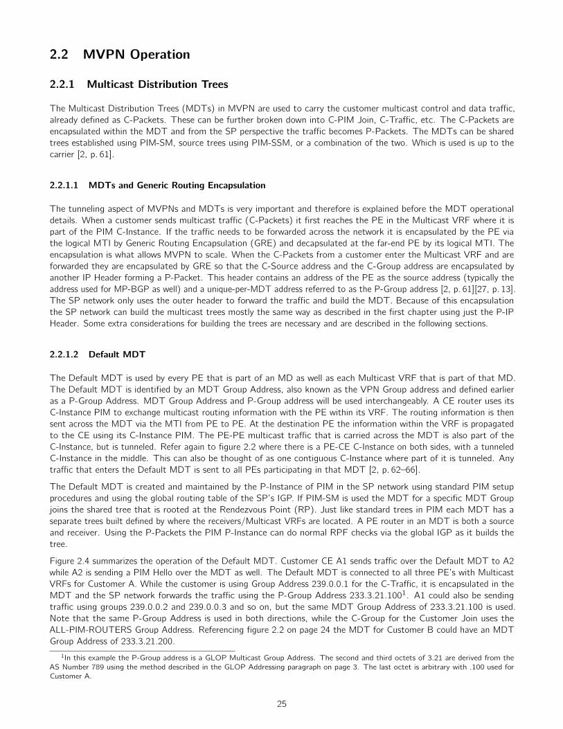
2.2 MVPN Operation
2.2.1 Multicast Distribution Trees
The Multicast Distribution Trees (MDTs) in MVPN are used to carry the customer multicast control and data tra�c,already defined as C-Packets. These can be further broken down into C-PIM Join, C-Tra�c, etc. The C-Packets areencapsulated within the MDT and from the SP perspective the tra�c becomes P-Packets. The MDTs can be sharedtrees established using PIM-SM, source trees using PIM-SSM, or a combination of the two. Which is used is up to thecarrier [2, p. 61].
2.2.1.1 MDTs and Generic Routing Encapsulation
The tunneling aspect of MVPNs and MDTs is very important and therefore is explained before the MDT operationaldetails. When a customer sends multicast tra�c (C-Packets) it first reaches the PE in the Multicast VRF where it ispart of the PIM C-Instance. If the tra�c needs to be forwarded across the network it is encapsulated by the PE viathe logical MTI by Generic Routing Encapsulation (GRE) and decapsulated at the far-end PE by its logical MTI. Theencapsulation is what allows MVPN to scale. When the C-Packets from a customer enter the Multicast VRF and areforwarded they are encapsulated by GRE so that the C-Source address and the C-Group address are encapsulated byanother IP Header forming a P-Packet. This header contains an address of the PE as the source address (typically theaddress used for MP-BGP as well) and a unique-per-MDT address referred to as the P-Group address [2, p. 61][27, p. 13].The SP network only uses the outer header to forward the tra�c and build the MDT. Because of this encapsulationthe SP network can build the multicast trees mostly the same way as described in the first chapter using just the P-IPHeader. Some extra considerations for building the trees are necessary and are described in the following sections.
2.2.1.2 Default MDT
The Default MDT is used by every PE that is part of an MD as well as each Multicast VRF that is part of that MD.The Default MDT is identified by an MDT Group Address, also known as the VPN Group address and defined earlieras a P-Group Address. MDT Group Address and P-Group address will be used interchangeably. A CE router uses itsC-Instance PIM to exchange multicast routing information with the PE within its VRF. The routing information is thensent across the MDT via the MTI from PE to PE. At the destination PE the information within the VRF is propagatedto the CE using its C-Instance PIM. The PE-PE multicast tra�c that is carried across the MDT is also part of theC-Instance, but is tunneled. Refer again to figure 2.2 where there is a PE-CE C-Instance on both sides, with a tunneledC-Instance in the middle. This can also be thought of as one contiguous C-Instance where part of it is tunneled. Anytra�c that enters the Default MDT is sent to all PEs participating in that MDT [2, p. 62–66].
The Default MDT is created and maintained by the P-Instance of PIM in the SP network using standard PIM setupprocedures and using the global routing table of the SP’s IGP. If PIM-SM is used the MDT for a specific MDT Groupjoins the shared tree that is rooted at the Rendezvous Point (RP). Just like standard trees in PIM each MDT has aseparate trees built defined by where the receivers/Multicast VRFs are located. A PE router in an MDT is both a sourceand receiver. Using the P-Packets the PIM P-Instance can do normal RPF checks via the global IGP as it builds thetree.
Figure 2.4 summarizes the operation of the Default MDT. Customer CE A1 sends tra�c over the Default MDT to A2while A2 is sending a PIM Hello over the MDT as well. The Default MDT is connected to all three PE’s with MulticastVRFs for Customer A. While the customer is using Group Address 239.0.0.1 for the C-Tra�c, it is encapsulated in theMDT and the SP network forwards the tra�c using the P-Group Address 233.3.21.1001. A1 could also be sendingtra�c using groups 239.0.0.2 and 239.0.0.3 and so on, but the same MDT Group Address of 233.3.21.100 is used.Note that the same P-Group Address is used in both directions, while the C-Group for the Customer Join uses theALL-PIM-ROUTERS Group Address. Referencing figure 2.2 on page 24 the MDT for Customer B could have an MDTGroup Address of 233.3.21.200.
1In this example the P-Group address is a GLOP Multicast Group Address. The second and third octets of 3.21 are derived from theAS Number 789 using the method described in the GLOP Addressing paragraph on page 3. The last octet is arbitrary with .100 used forCustomer A.
25

4
3
5
1
7
A1
A2
2
6
A3
Join PathTraffic Path
C-Source: 10.1.1.1C-Dest: 239.0.0.1
C-Source: 10.1.2.1C-Dest: 232.0.0.13
C-Source: 10.1.2.1C-Dest: 232.0.0.13P-Source: 1.1.1.6
P-Dest: 239.3.21.100
C-Source: 10.1.1.1C-Dest: 239.0.0.1P-Source: 1.1.1.1
P-Dest: 239.3.21.100
C-Source: 10.1.1.1C-Dest: 239.0.0.1P-Source: 1.1.1.1
P-Dest: 239.3.21.100
Figure 2.4: MVPN Default MDT Operation
The Default MDT has a single P-Group address but is carrying multiple customer (S,G) streams, which use a C-SourceAddress and a C-Group Address. The customer streams can be referred to as (C-S,C-G). Each MDT may be denoted as(P-S,P-G).
2.2.1.3 Data MDT
The Default MDT always sends all tra�c to PEs that are participating in that particular MDT. When the amount oftra�c gets larger this method becomes more and more ine�cient. To regain e�ciency of delivering multicast tra�cto only the PEs that have active receivers the Data MDT is used. The Data MDT can be created when a configuredbandwidth threshold is crossed for the Default MDT. One or more Data MDTs can be created in addition to the DefaultMDT and each MDT receives a unique group address which can be obtained from a pool of P-Group addresses. TheData MDT also only handles data tra�c; control tra�c is only sent over the Default MDT.
The PE router tracks the amount of bandwidth for each (C-S,C-G) customer stream and creates a new Data MDT ifthat particular group exceeds the user configured bandwidth threshold. The PE does not create a new Data MDT basedsolely on the aggregate tra�c amount for all groups traversing a Default MDT. Each (C-S,C-G) stream gets its ownData MDT if it crosses the bandwidth threshold. However if the amount of P-Groups in the pool is exceeded then the PErouter will put more than one customer (C-S,C-G) stream onto a Data MDT. The trade-o↵ is that a smaller P-Grouppool allows for fewer MDTs, which means less P-Instance PIM state, but a larger pool allows for more optimization butwith more P-Instance state.
Just like the Default MDT the Data MDT is created using P-Instance PIM. The PE router with active receivers cansend a PIM P-Join message, but first it needs to learn of the P-Group address of the Data MDT. To facilitate this a newcontrol message is created called a Data MDT Join. The PE with an active source sends the Data MDT Join to allthe PEs participating in the Default MDT using a destination address of 224.0.0.13, the ALL-PIM-ROUTERS GroupAddress. The message payload consists of the customer’s (C-S,C-G) information (the customer’s source address andgroup address for a stream) along with the Data MDT’s P-Group address. A PE router with receivers for that particular
26

(C-S,C-G) stream will then join that Data MDT. PE’s that do not have active receivers will still store the Data MDTJoin information in case an active receiver does want to join that (C-S,C-G) stream. The source PE that initiated theData MDT will wait several seconds before putting tra�c onto the Data MDT to allow for time for the receiving PEs toset up the tunnel [2, p. 66–67].
The Data MDT can be setup by using either PIM-SM or PIM-SSM. If PIM-SM is used the PE routers, upon receipt ofthe Data MDT Join, will send a P-Join back toward the P-RP of the shared tree. If PIM-SSM is used the receiving PEwill send a P-Join back to the source PE router creating a source tree. RFC 6037 recommends the use of PIM-SSM [27,p. 16–17].
4
3
5
1
7
A1
A2
2
6
A3
Data MDT Join PathP-Join
C-Source: 10.1.1.1C-Group: 239.0.0.2
P-Group: 239.3.21.101
P-Source: 1.1.1.1P-Group: 239.3.21.101
Figure 2.5: MVPN Data MDT Signaling
Figure 2.5 shows the source PE advertising the Data MDT Join over the Default MDT. In contrast to creffig:mdtdefaulta new P-Group Address of 233.3.21.101 is used for the Data MDT instead of .100 which is already used for the DefaultMDT. The (C-S,C-G) of (10.1.1.1,239.0.0.2) is the customer stream that crossed the bandwidth threshold configuredon the PE. Only PE 5 has active receivers for this customer stream so it sends a P-Join back to the source PE using thePIM-SSM method. Figure 2.6 below shows the customer tra�c traversing the new Data MDT. Note that the tra�c forthis group is encapsulated using the new P-Group Address specific to the Data MDT of .101.
27

4
3
5
1
7
A1
A2
2
6
A3
Data MDT Join PathP-Join
C-Source: 10.1.1.1C-Group: 239.0.0.2P-Source: 1.1.1.1
P-Group: 239.3.21.101
Figure 2.6: MVPN Data MDT Operation
2.2.2 Auto-Discovery in MVPNs
The P-Group Address for an MDT is manually configured on a router. When PIM-SM is used to build the trees thestandard mechanisms are used, where the source and receiver PEs can discover each other through the RP. The receiverPE is sending (*,G) PIM P-Joins toward the RP while the source is sending Register Messages toward the RP. Becauseof the use of (*,G) the receiver PE does not need to know the source PE’s unicast source address for that particulargroup [2, p. 105]. Each PE only needs to know the P-Group address for the MDT [27, p. 8].
Using PIM-SSM for MDT setup requires an additional mechanism for auto-discovery since the receiver PE does not knowthe source PE’s IP address2. The mechanism created is a new BGP Address Family called MDT SAFI. This AddressFamily uses an AFI of 1 and a SAFI of 66. The NLRI field contains one or more of the 2-tuple of an RD prepended tothe IPv4 address used as the source address plus the P-Group Address.
+————————————————+| RD:IPv4 Source Address (12 octets) |+————————————————+| P-Group Address (4 octets) |+————————————————+
A Route Target (RT) is also included in the same UPDATE message that contains the MP-BGP Address Family forMDT SAFI. Using normal BGP VPN mechanisms the route information can be associated with the correct VRF. TheP-Group could also be used, but this would require that all P-Groups are unique across a multi-provider network. This isdi�cult, so the RFC specifies that RTs must always be used to facilitate the use of multi-provider networks [27, p. 8–10].Each BGP speaker participating in MVPN receives the MDT SAFI information and uses the Route Targets to install
2Contrast this to a typical SSM case in a non-MVPN network where a host is trying to join a specific group and source: The IGMPv3Membership Report (IGMP Join) has the source included in it along with the group it’s trying to join. The router then turns this into a (S,G)PIM Join. In the MVPN case in the P-Instance there is no host joining a group using a specific source; only the P-Group Address is knownfrom manual configuration.
28

the information into the correct VRF. Each PE router can then join the (S,G) tree using normal PIM processes [2,p. 105–106].
2.2.3 RPF
Reverse Path Forwarding (RPF) checks are a fundamental part of multicast and are still needed in an MVPN environment.In a typical PIM network the check occurs by making sure tra�c is arriving over the interface that is part of the shortestpath back to the source according to the global unicast routing table. This check needs be a handled a little di↵erentlywhen in a Multicast VRF that consists of MDT MTIs. The check can occur normally for the PIM P-Instance since this ispart of the global table. Within the VRF the C-Instance tra�c can either be sourced from a CE interface or from theMDT’s MTI for the MVPN. If it is received from the CE interface a normal RPF check can occur since that interface isparticipating in the VRF’s routing table. However if the packets are received from another PE on the other side of theMDT the VRF doesn’t automatically have the route toward the other PE. In this case, the routes within a VRF for theother PEs in the MDT are provided by VPNv4 BGP. The RPF check within the Multicast VRF will set the upstreaminterface as the MTI if the VPNv4 message contains a C-Source address. The RPF neighbor address is set to be theBGP Next Hop address within the VPNv4 message, and PIM will use this address when sending Hello Messages acrossthe MDT. With these modifications the MTI is treated just like a physical interface on the router, and PIM simply usesthe BGP Next Hop as the PIM neighbor on the other side of the MDT [2, p. 70].
2.3 Considerations for Inter-AS and BGP Free Core
When a BGP free core is used, or in Inter-AS scenarios, extra information is necessary for RPF checks or PIM signalingto occur. RFC 6037 specifies two new methods to allow for communication in these scenarios.
2.3.1 PIM MVPN Join Attribute
The PIM MVPN Join Attribute, also called the PIM RPF Vector or PIM Vector, is used to assist with Inter-AScommunication or BGP-Free Core communication. The PIM Vector is a new PIM Join Attribute, an extension of PIM.The PIM Vector contains the IP address of the router that has reachability to the source (the IP address that the PIMJoin/Prune should be forwarded to), and an RD. The RD is taken from the BGP MDT SAFI UPDATE Message [27,p. 11–13][2, p. 122–123].
Using MVPN and BGP MDT advertisements the PE will be aware of the source address, but it is kept outside of the IGPtable and is in the special BGP MDT SAFI Table. The PIM Vector helps in a BGP free core, or in an inter-AS scenario,where the source address isn’t known because it’s not in the IGP table. PIM relines on the IGP table, and there is noBGP MDT Table, since that is only on the PE routers or ASBR router. Instead, P-PIM can use the IP address of theRPF Vector, which is an IP address of a router that knows how to reach the source PE. The source PE is aware of theBGP MDT Table and the global IP address used in the PIM Vector. The RD is required so that the PE can associatethe PIM message with the appropriate BGP MDT Table [2, p. 123].
2.3.2 BGP Connector
With each VPNv4 UPDATE message that a PE distributes from a Multicast VRF it must carry the BGP ConnectorAttribute. It is an optional transitive attribute [27, p. 15–16]. The value of the attribute is the IP address of the PE (likelythe loopback). For Intra-AS communication it doesn’t have much purpose, but for Inter-AS “Option-B” communicationit has significance, when the ASBR changes the next-hop of the UPDATE message. This allows the originating PE’srouter address to be preserved. This allows the far-end PE in the other AS to fulfill its RPF check [2, p. 116–117].
29

Chapter 3
BGP/MPLS Multicast Virtual PrivateNetworks
While Draft Rosen MVPNs were able to allow Service Providers (SPs) to create scalable Multicast Private Networks,Draft Rosen does have its limitations. For one, the SPs are not able to leverage the MPLS technology already deployedin their network. The Draft Rosen method utilized GRE to create the tunnel between the edges through the core whichcreated an overlay network. This results in the SP having to maintain a PIM/GRE topology in addition to a BGP/MPLStopology for the traditional RFC 4364 Unicast VPNs. In a large SP network with many customers a large amount of PIMstate also had to be maintained by the routers in the core, when there is the preference by many SPs to keep their coressimple and only label-switch tra�c. The Default MDT was ine�cient in the sense that all PEs had to receive C-Packetseven if there weren’t any receivers, and higher amounts of tra�c caused more state to be created to support multipleData MDTs [2, p. 153–154].
BGP/MPLS Multicast VPNs were created to extend the use of Unicast VPNs, as defined in RFC 4364, to carry customermulticast tra�c. The RFC defines a framework to allow an SP to carry multiple C-Multicast streams without requiringthe amount of state in the SP network to increase proportionally. The primary method for accomplishing this is byaggregating multiple customer streams into a single distribution tree throughout the backbone P routers. Multipleaggregation methods are defined [28, p. 5–7]. BGP/MPLS Multicast VPNs are defined in RFC 6513, which provides theoverview and framework, and RFC 6514 which includes detailed information about the BGP encodings defined within RFC6513. Eric Rosen co-authored RFC 6513 along with Rahul Aggarwal and both are the main authors for RFC 6514.
RFC 6513 defines an Multicast VPN (MVPN) as two sets of sites, a Sender Site and a Receiver Site. The tra�coriginated by a Sender Site should only be received by its corresponding set of Receiver Sites, and not any other ReceiverSite not in that set. In other words Customer A Sender tra�c should only be received by receivers at Customer A sites.Or, Customer A can send tra�c to another customer if it allows that to happen, which would imply that the othercustomer is in Customer A’s receiver set. This would be the case in an extranet. The MVPN capabilities are carried outusing RFC 4364 mechanisms.
In this chapter the Draft Rosen MVPNs will be referred to as DR-MVPNs and the BGP/MPLS Multicast VPNs describedin RFCs 6513 and 6514 will be referred to as Next-Generation MVPNs (NG-MVPNs). This chapter will also use thesame convention of distinguishing customer and provider elements with the C- and P- prefix. Some terms will be carriedover as well, such as P-Group Address.
3.1 Next-Generation Multicast VPN Overview
In an NG-MVPN network the role of BGP is to convert PIM messages from a customer on a PE into special BGPmessages, send them across the network, and convert them back to PIM at the far end PE for hando↵ to the customerat another site. Using the Unicast BGP/MPLS procedures defined in RFC 4364 the PE can map these messages toa specific Multicast enabled VRF. BGP is also responsible for autodiscovery using a set of special BGP messages andbinding C-Multicast routes to whichever provider tunnel is chosen. Using information carried within BGP the PEs can
30

also establish a variety of P-Tunnels. One option is be PIM/GRE based tunnels as in DR-MVPNs. However, there arealso MPLS based options, including RSVP-TE which can allow for tra�c engineering of the multicast tra�c. Withthe inclusion of MPLS technologies for transport and the use of BGP for control plane the technology has the nameBGP/MPLS Multicast VPNs [13, p. 287-292].
PA1
A2
PE1
M-VRF A
PE6
A3
PE5
PIM Control Plane
BGP Control PlaneP-Tunnel ForwardingC-Traffic (Tunneled)
M-VRF A
M-VRF A
PIM Control Plane
PMSI
C-PayloadC-IP Header
Transport Type
C-PayloadC-PIM
C-PayloadC-PIM
Figure 3.1: BGP/MPLS Multicast VPN
The above figure is purposefully similar to figure 2.2 on page 24 to compare and contrast the two technologies. AsDR-MVPN there is a P2MP P-Tunnel; however the P-Tunnel can be a variety of options using PIM/GRE and MPLS.Rather than an MTI, NG-MVPN uses a somewhat similar concept of a PMSI at the endpoints of the P-Tunnel. Also,the control plane is no longer solely PIM but is now MP-BGP within the SP network. In both cases, the C-Tra�c istunneled throughout the multicast network. NG-MVPNs can be broken up into two parts: control plane and forwardingplane. The control plane is the combination of PIM and BGP while the forwarding plane are the various options fortransporting the customer multicast tra�c across the network, such as MPLS.
3.2 PMSI
As with DR-MVPN, NG-MVPN also has multicast distribution trees. The two types are Inclusive Trees and SelectiveTrees. An Inclusive Tree includes all of the C-Multicast Tra�c of the PEs that are members of the same MVPN. Thenumber of Inclusive Trees is bound by the number of VPNs on a PE router, not by the number of C-Multicast groups.Selective Trees carry only one or more C-Multicast Groups for a given MVPN. In other words, they don’t carry all ofthe C-Multicast groups for a customer. A PE can by default carry all tra�c on an Inclusive Tree and elect to onlyput higher bandwidth flows onto separate Selective Trees. The Selective Trees should be configured so that they onlyterminate on PEs that actually have active receivers [28, p. 7–8]. Inclusive trees also have two subtypes: Multidirectionaland Unidirectional (MI-PMSI and UI-PMSI). The Multidirectional tree is akin to a broadcast network where any PEthat sends a message will have that message sent to any other PE on the MI-PMSI. The Unidirectional PMSI allows aparticular PE to send tra�c to any other PE in that MVPN [28, p. 15–16]. The di↵erence may not be obvious betweena MI-PMSI and a UI-PMSI. A MI-PMSI can be thought of a set of UI-PMSIs that create full-mesh connectivity in anMPVN. This may become more clear when explained in the subsection regarding instantiation of PMSIs in section 3.2.1.
31

The MI-PMSI is used in special circumstances not used in this report (such as PIM as the PE-PE Control Plane or theuse of PIM-BIDIR) so only I-PMSI will be used.
The Inclusive Tree and Selective Tree are akin to the Default MDT and Data MDT of DR-MVPNs respectively. Bothinclusive and selective trees can be aggregated into another tunnel as an aggregated inclusive tree and/or an aggregatedselective tree. This is discussed more in depth in section 3.4.6.
A PE needs the ability to send packets over one or more trees that belong to an MVPN. This concept is realized byProvider Multicast Service Interfaces (PMSIs). A C-Packet sent via a PMSI will be delivered to some or all of the PEsparticipating in the MVPN, and any receiver will be able to determine which VPN the C-Packet resides in. The PMSI isthe entry point for a P-Tunnel, which is the transport mechanism used for delivering C-Packets. RFC 6513 clarifies thata PMSI is not necessarily part of a P-Tunnel, as a single P-Tunnel can carry multiple PMSIs [28, p. 14–15]. The PMSI isalso an abstract concept. When a PE gives a packet to the PMSI it will arrive at one or all of the PEs that belong to agiven MVPN. A PE may send C-Tra�c to the PE routers that have receivers for that tra�c or to all of the PE routersin that MVPN. BGP is used to signal which type of PMSI should be used by including a PMSI Tunnel Attribute that isincluded in a NG-MVPN BGP UPDATE [2, p. 157–158].
There are two types of PMSIs. The first is an Inclusive PMSI (I-PMSI). The I-PMSI is used when a PE can send amessage that will be received by all the PEs for that MPVN. Another type of PMSI is the Selective PMSI (S-PMSI).The S-PMSI is used so that a message will be sent to only selected PEs participating in an MVPN [28, p. 15–16]. Itis possible to send tra�c only on S-PMSIs and never use an I-PMSI for carrying C-Multicast Tra�c which allows forfurther optimization [28, p. 19].
4
3
5
1
7
A1
A2
2
6
A3 4
3
5
1
7
A1
A2
2
6
A3
Customer A MVRFCustomer A P-Tunnel
I-PMSI S-PMSI
Figure 3.2: Provider Multicast Service Interface
Figure 3.2 shows an I-PMSI and an S-PMSI. The PMSI can be thought of the interface to the P-Tunnel, however foreach P-Tunnel there may be more than one PMSI. The I-PMSI connects to all the PEs for Customer A, while the S-PMSIconnects to only one PE. The S-PMSI may also carry only a subset of the multicast groups for the MVPN.
32

3.2.1 Instantiating PMSIs
A PMSI is instantiated by P-Tunnels, which are the encapsulation and forwarding method for multicast tra�c in NG-MVPN.The P-Tunnels can be created by PIM, mLDP, RSVP-TE, or replication over P2P Unicast P-Tunnels. In the PIM case,as is in DR-MVPN, there is a P-Instance of PIM that is used to create the tunnels. These can be either source treeor shared tree methods, but an S-PMSI is best created using source tree methods. Using mLDP P2MP can create anS-PMSI or a UI-PMSI, and MP2MP mLDP can create a MI-PMSI. An MI-PMSI can also be created by a set of P2MPmLDP LSPs. RSVP-TE can instantiate an S-PMSI or a UI-PMSI with a single set, where multiple sets can instantiate anMI-PMSI (one by each PE in the MPVN). Unicast P-Tunnels are either a partial or full mesh for UI-PMSI and S-PMSI orMI-PMSI respectively.
P-Tunnels are discussed in detail in section 3.4.
3.3 PIM and BGP Control Plane
NG-MVPN requires that a PE maintains at most one BGP peering session with all the other PEs in the network, or witha Route Reflector (RR), for carrying the NG-MVPN control information [28, p. 11]. This report only considers usingBGP for PE-PE control information and not PIM. In other words, the report only considers translating, for example,PIM C-Join messages into BGP C-Multicast Routes, and not forwarding the PIM Join over a PMSI. The description forPE-CE PIM and PE-PE BGP components are covered below.
3.3.1 PIM Control Plane for CE-PE Information
Similar to Unicast BGP/MPLS VPNs, NG-MVPNs have the CE peer only with the directly attached PE using a multicastrouting protocol over the attachment circuit (AC). The CE does not peer with the remote CE on the other side of theSP network. The AC is part of a VRF that is configured to be multicast enabled. As with DR-MVPNs these multicastpeering sessions between the CE and PE are referred to as multicast C-Instances. The VRF that the AC is attachedto contains both unicast and multicast routing instances. RFC 6513 specifies the use of PIM-SM, PIM-SSM, andBidirectional PIM (BIDIR-PIM) as the PE-CE protocols [28, p. 13]. The PE-PE support methodology for BIDIR-PIM willnot be discussed in this report.
3.3.2 MP-BGP Control Plane for PE-PE Information
New Path Attributes, Extended Communities, and NLRI Encodings (referred to as Route Types) were created to supportNG-MVPNs and are included in NG-MVPN BGP UPDATE Messages. The following sections describe in detail eachaddition.
3.3.2.1 New BGP Path Attributes and Extended Communities
RFC 6514 defines three new path attributes that are used in conjunction with the new NLRI encodings described in thenext section.
PMSI Attribute The P-Tunnel Multicast Service Interface (PMSI) Attribute in a BGP UPDATE message identifieswhich type of P-Tunnel is used to send tra�c. This is an optional transitive attribute. The PMSI Attribute is made up offour fields as follows [29, p. 10–11]:
33

+————————————————-+| Flags (1 Octet) |+————————————————-+| Tunnel Type (1 octet) |+————————————————-+| MPLS Label (3 Octets) |+————————————————-+| Tunnel Identifier (Variable) |+————————————————-+
The Flags field only has one flag which indicates of leaf information is required. The MPLS Label field is either set tozero to indicate there is no label, or a label value is encoded in the high-order 20 bits of the three octets [29, p. 10]. TheMPLS Field is used when the ingress PE uses “upstream label allocation” to distribute a label to an egress router [30,p. 9]. The Tunnel Type field has the following values [29, p. 10]:
• 0 - No Tunnel Information Present
• 1 - RSVP-TE P2MP LSP
• 2 - mLDP P2MP LSP
• 3 - PIM-SSM Tree
• 4 - PIM-SM Tree
• 5 - BIDIR-PIM Tree
• 6 - Ingress Replication
• 7 - mLDP MP2MP LSP
Depending on the value in the Tunnel Type field the Tunnel Identifier includes the following information [29, p. 10–13]:
No Tunnel Information Present No tunnel information is included. This setting can be used when a PE needs to knowthe receivers before it establishes a tunnel. The “Leaf Information Required Bit” is set in this case, which willprompt the other PEs to send Leaf A-D route messages [28, p. 52].
RSVP-TE P2MP LSP The same information in the P2MP Session Object is included. This is the Extended Tunnel ID,Tunnel ID, and P2MP ID.
mLDP P2MP LSP The P2MP FEC Element is included. This is the combination of the source address of the LSPtree and a unique value.
PIM-SSM Tree The P-Root Node Address (P-Source Address of the PE) and the P-Group Address. The P-Groupaddress is an address from the P-Instance of PIM running in the service provider network.
PIM-SM Tree The Sender Address and the P-Group Multicast Address.
BIDIR-PIM Tree BIDIR-PIM uses the same Tunnel Information as PIM-SM.
Ingress Replication The unicast IP address of the tunnel endpoint.
mLDP MP2MP LSP The MP2MP FEC Element, which is similar to the P2MP FEC in concept, and is not discussedin this report.
Section 3.4 discusses the various types of P-Tunnels in depth, except for BIDIR-PIM and mLDP MP2MP, which will notbe covered in this report.
Source AS Extended Community This BGP Extended Community is set to the AS Number (ASN) of the SP networkthat the PE belongs to. It is used for identifying the ASN, and has particular use for Inter-AS updates. It is an optionaltransitive attribute. A unicast BGP/MPLS UPDATE Message must carry this Extended Community [29, p. 13].
34

VRF Route Import Extended Community Every Multicast VRF is required to have an import Route Target configured,which is similar use to the Unicast BGP/MPLS VPNs import/export Route Target. This Route Target is referred to asthe C-Multicast Import RT. It contains two fields. One is the “Global Administrator Field” which contains an IP addressof the PE that is the same across all VRFs (e.g. a loopback address on the PE). The other is the “Local AdministratorField” which is set to a unique 16-bit number that can identify a VRF. The combination of the Global and Local Fieldscan uniquely Identify a VRF [29, p. 14].
An important clarification from unicast BGP/MPLS RTs is that The C-Multicast Import RT is also dynamic in the sensethat the Global Admin Field always contains the IP address of the active sender, which can change [2, p. 166].
The C-Multicast Import RT is just the value that is configured for a particular VRF, and is carried to other PEs byputting the value into the RT Extended Community of a BGP UPDATE message. Of the special BGP/MPLS MVPNRoutes, which are described in section 3.3.2.2, C-Multicast Import RTs are only carried by the Route Target ExtendedCommunities of C-Multicast Routes (Type 6 and 7) [2, p. 166]. Outside of these special routes, the C-Multicast RTvalue must also be carried in the VRF Route Import Extended Community of a BGP UPDATE Message for a unicastBGP/MPLS VPN Route. These unicast routes represent the source of a particular C-Multicast flow. However, if it isknown that none of the unicast routes are capable of being a source, then the route should not carry the VRF RouteImport EC [29, p. 14].
3.3.2.2 MCAST-VPN NLRI
RFC 6514 defines a new MP-BGP NLRI with a set of NRLI encodings for two purposes: MVPN auto-discovery (A-D)and binding as well as advertisement of C-Multicast Routes. Each NRLI encoding is known as a Route Type. One ofthese Route Type may indicate the type of PMSI that is going to be signaled, or it may indicate that a PE has a receiverready to receive tra�c. As discussed earlier there are multiple types of PMSIs and BGP is used to signal which types areused for an MVPN. The first five Route Types are for auto-discovery and binding information are as follows:
• Intra-AS I-PMSI A-D route
• Inter-AS I-PMSI A-D route
• S-PMSI A-D route
• Leaf A-D route
• Source Active A-D route
The last two Route Types are for carrying C-Multicast Route information, “C-Multicast Routes”. Each VRF contains aunique Tree Information Base (MVPN-TIB) containing the C-Multicast Routes for that particular VRF. The two RouteTypes are as follows:
• Shared Tree Join Route
• Source Tree Join Route
The NLRI is identified by AFI 1 and SAFI 5 (MCAST-VPN) and consists of three fields. The first is the Route Type fieldwhich identifies which Route Type will be encoded in the NLRI. The next field is the length field to specify how many bitswill make up the actual Route Type encoding [29, p. 4-6].
+————————————————-+| Route Type (1 Octet) |+————————————————-+| Length (1 octet) |+————————————————-+| Route Type specific (Variable) |+————————————————-+
Each NLRI Route Type encoding is described below along with its behavior in an NG-MVPN network.
35

Route Type 1 - Intra-AS I-PMSI A-D The Intra-AS I-PMSI A-D route is advertised by any PE that wishes toparticipate in NG-MVPN auto-discovery and binding.
+————————————————-+| Route Distinguisher (8 Octets) |+————————————————-+| Originating Router’s IP Address |+————————————————-+
The NLRI contains an RD that is configured for the VRF that the route originated from along with the same IP addressthat it uses in the VRF Route Import EC that was used in a Unicast BGP/MPLS advertisement for that VRF (e.g. aloopback address). The combination of the RD and the Originating Router’s IP address uniquely identifies a MulticastVRF. The advertisement only contains the Tunnel Attribute field if an I-PMSI is being created (remember that anI-PMSI does not need to be used and the network can use solely S-PMSIs). In other words, in any case, the PE send thistype of advertisement. If the I-PMSI is being used then the advertisement must contain the PMSI Attribute, and ifIngress Replication is used it must contain a label for demultiplexing at the receiver end. The Next Hop field of theMP REACH NLRI that contains the MCAST-VPN Route must be set to the same address as the Originating Router’sIP Address field. The advertisement also uses the same Route Target values as the Unicast BGP/MPLS export routesfor that VRF.
Upon receipt of the I-PMSI Intra-AS advertisement, the receiving PE will import the routes into the VRF if the RouteTarget in the RT EC of the route matches the RT value configured for the VRF. When the receiving PE receives theIntra-AS Route advertisement and it does not have the PMSI Tunnel Attribute and Ingress Replication is not used thereceiving PE can assume that (1) only an S-PMSI will be used, or (2) that the originating PE of the advertisementcannot send multicast tra�c (i.e.it is only a receiver). To determine whether it’s case 1 or 2 the VRF Route Import ECis used. If the VRF Route Import EC is not present for a unicast BGP/MPLS route, then the PE that originated thecannot be selected as a source PE (as it does not have routes with a source). Therefore it is case (1), and this PE willonly be used for originating S-PMSI routes.
If a Tunnel Attribute is carried and Ingress Replication is used then the MPLS Label and the Address in the TunnelIdentifier should be used when the local PE sends tra�c to the PE that originated the route. In all other cases the localPE should join the P-Tunnel (if RSVP-TE is used then the sender PE is responsible to building the tunnel to the localPE).
The only time an Intra-AS I-PMSI Route is not originated by a PE is when a MVPN site will not be receiving anymulticast tra�c (i.e. it is only a sender) and Ingress Replication is used.
An example of an Intra-AS I-PMSI A-D route as it is shown in a router’s routing table:1:789:100:1.1.1.1, where 1 is the Route Type, 789:100 is the RD, and 1.1.1.1 is the IP address of the originating router[31].
Route Type 2 - Inter-AS I-PMSI A-D This Route Type is only used when Inter-AS segmented tunnels are usedbetween AS networks. Only an ASBR originates this route.
+————————————————-+| Route Distinguisher (8 Octets) |+————————————————-+| Source AS (4 Octets) |+————————————————-+
The RD is encoded the same as it is in Unicast BGP/MPLS VPNs. The Source AS contains an AS Number of theoriginating router, and occupies the low-order 16 bits of the field. The high-order bits are set to zero. This Route Type isoriginated when an ASBR determines, using Type 1 Routes, that there is an active receiver in its own AS. The Inter-ASI-PMSI A-D Route also carries an import Route Target called “ASBR Import RT” (which is the unicast RT), whichallows for the accptance of Leaf A-D route and C-Multicast routes from an ASBR. The ASBR sends the advertisementvia external BGP to the neighboring AS. It sends the message with the “Leaf Information Required” flag set, and doesnot send any label. The Next Hop field of the MP REACH NLRI field is set to an IP address that is reachable by a
36

router in the other AS. In the network that is on the other side of the ASBR the identification of a source becomes thepair of AS and RD, rather than PE and RD. This means that even with multiple trees on the source AS side, the otherAS may have just one MVPN for all of the MVPNs in the source AS.
Upon receipt of the I-PMSI Inter-AS advertisement, the receiving PE will import the routes into the VRF if the RouteTarget in the RT EC of the route matches the RT value configured for the VRF. If the router is an ASBR it will pass theroutes along in external BGP. If the PMSI Attribute carries a Tunnel Type for PIM-SM/SSM or mLDP P2MP Tree, thereceiving router should join the tree using the identifying information carried in the Tunnel Identifier field of the attribute.If the Tunnel Identifier is set to RSVP-TE P2MP Tree, then the originating router is required to build the sub-LSP tothe receiving router (this may have been done already as the headend is responsible for initiating the LSP construction inRSVP-TE). If the “Leaf Information Required” bit was set then the receiving router will originate a Leaf A-D Route.The Leaf A-D Route Key is populated with the MCAST VPN NLRI information from the Inter-AS I-PMSI advertisement[29, p. 20–30].
An example of an Inter-AS I-PMSI A-D route as it is shown in a router’s routing table:2:789:100:789, where 2 is the Route Type, 789:100 is the RD, and 789 is the source AS Number of the originatingrouter [31].
Route Type 3 - S-PMSI A-D The S-PMSI A-D Route Type is only used when the C-Multicast stream has a specificC-Source address (C-S,C-G).
+————————————————-+| Route Distinguisher (8 Octets) |+————————————————-+| Multicast Source Length (1 Octet) |+————————————————-+| Multicast Source (variable) |+————————————————-+| Multicast Group Length (1 octet) |+————————————————-+| Multicast Group (variable) |+————————————————-+| Originating Router’s IP Address |+————————————————-+
The RD is the same as in the Inter-AS and Intra-AS I-PMSI Route. The Multicast Source contains the IP address of theC-Multicast source IP address. The Multicast Group contains the C-Multicast Group Address or the mLDP P2MP FECvalues when P2MP mLDP is used. The Originating Router’s IP Address is that of the PE, not the CE, as with theIntra-AS I-PMSI A-D message, and it needs to be the same as the address used in the VRF Route Import ExtendedCommunity (e.g. a loopback address). This Route Type carries the PMSI Tunnel Attribute which contains the identityof the P-Multicast Tree used for the P-Tunnel. If the originating PE needs to learn about the leaves of the P-Multicasttree it can set the “Leaf Information Flag” bit. An ASBR in certain circumstances may convert one or more receivedS-PMSIs from another AS into one I-PMSI and distribute it toward the receiver in its own AS.
The process when receiving an S-PMSI A-D route is the same as described for the Inter-AS I-PMSI A-D Route. Ifthe “Leaf Information Required” bit is set then the receiving PE originates a Leaf A-D route. The Route Key Field ispopulated with the MCAST VPN NLRI information from the S-PMSI A-D Route [29, p. 40–45].
An example of an S-PMSI A-D route as it is shown in a router’s routing table:3:789:100:32:10.1.1.1:32:239.0.0.1:1.1.1.1, where 3 is the Route Type, 789:100 is the originating router’s RD, 32 is thelength of the address (indicating IPv4) in both locations, and 10.1.1.1 is the C-Source Multicast Address, 239.0.0.1 isthe C-Group Address, and 1.1.1.1 is the Originating Router’s IP Address [31].
Route Type 4 - Leaf A-D Route The previous three Route Types mentioned the Leaf A-D Route. The Leaf A-DRoute is sent in response to an advertisement that contains the PMSI Tunnel Attribute with the “Leaf InformationRequired” bit set to 1 in an Inter-AS I-PMSI A-D Route or in an S-PMSI A-D Route.
37

+————————————————-+| Route Key (variable) |+————————————————-+| Originating Router’s IP Address |+————————————————-+
The Route Key field carries the MCAST VPN NLRI information from whichever type of PMSI A-D Route it received(either Inter-AS Inclusive or Selective). If the Tunnel Type from the received advertisement is Ingress Replication thenthe Leaf A-D needs to set Ingress Replication in its PMSI Tunnel Attribute Tunnel Type field, and it also needs tocarry a label. This label will be placed on the stack by the ingress PE (the same one that originated the PMSI A-Dadvertisement) so the MVPN tra�c can be demultiplexed into the correct Multicast VRF by the egress PE (the same onethat originated the Leaf A-D advertisement). The Next Hop of the MP REACH NLRI in the Leaf A-D Message must beset to the same IP that is in the Originating Router’s IP Address field. The Leaf A-D advertisement also contains anIP-Based RT EC that is based on the IP address carried in the Next Hop field of the received PMSI A-D advertisement(the sender PE’s IP address) in the Global Admin Field. The Local Admin field is set to zero [29, p. 29]. Zero is usedbecause the correct VRF can be determined by the corresponding Route information in the Route Key field [32].
An example of a Leaf A-D route as it is shown in a router’s routing table:4:3:32:10.1.1.1:32:239.0.0.1:1.1.1.1:1.1.1.7, where 4 is the Route Type. In this example, after the 4:, the S-PMSIMCAST VPN NLRI information is copied, which makes the Route Key field. The trailing 1.1.1.7 is the OriginatingRouter’s IP Address (of the PE that is sending the Leaf A-D advertisement) [31]. The scenario in this example is thatthe PE 1.1.1.1 originated an S-PMSI A-D Route and the PE 1.1.1.7 is responding with a Leaf A-D Advertisement.In a common scenario, an ingress (source) PE will originate a Type 3 S-PMSI A-D Route with the “Leaf InformationRequired” bit set. Receiver PEs that have active receivers will respond with a Type 4 Leaf A-D Route. This is thestandard process when using S-PMSIs [30, p. 17].
Route Type 5 - Source Active A-D Route The Source Active A-D Route is used to advertise if a PE has an activesource. The Source Active A-D Route is only used for groups outside the 232/8 range for SSM and only in conjunctionwith Source Tree C-Multicast Join (Route Type 7) [29, p. 9]. When using the SSM range a PE will simply use theSource Tree C-Multicast Route [32].
+————————————————-+| Route Distinguisher (8 Octets) |+————————————————-+| Multicast Source Length (1 Octet) |+————————————————-+| Multicast Source (variable) |+————————————————-+| Multicast Group Length (1 octet) |+————————————————-+| Multicast Group (variable) |+————————————————-+
The Source Active A-D Route is only used in conjunction with C-Trees when they switch from a shared tree to a sourcetree, or when the C-Tree is only a source tree. Depending on the scenario the fields are populated di↵erently, except theRD field which takes the standard RD encoding from the Multicast VRF in Unicast BGP/MPLS format. In both casesthe Source and Group fields are the C-Source and C-Group addresses. However in the procedure that is solely sourcetree the C-Source and C-Group are received from PIM Register messages1. The MP REACH NLRI Next Hop is thesame as the address carried in the VRF Route Import EC of the unicast BGP/MPLS routes that are advertised by thePE, and should carry the same Route Targets as the Intra-AS I-PMSI A-D Route the PE originates. The Source ActiveA-D Route is propagated to all of the PEs of the MVPN [29, p. 46–47].
1It can also come from an MSDP Source-Active Message but that is outside the scope of this report
38

Source Tree OnlyThere are three ways that a PE can learn about an active multicast source in this scenario. One is for the PE to be aC-RP. A second way is to use PIM Anycast RP procedures. Another way is to use MSDP to exchange the informationfrom the C-RP to the PE. Once a new source is learned using any of these methods the PE will send a Source Active A-Droute to all PEs within the same MVPN [29, p. 49–52]. This is the default method for NG-MVPN. PEs with receiversfor the C-Group in the Source Active message will respond with a Type 7 C-Multicast route toward the ingress PE [2,p. 162].
Shared Tree changing to Source TreeIn certain situations the default method is not suitable. One such situation is when the C-RP is not on a PE and MDSPis not used. In this case a Shared Tree method is used where Joins are sent to the RP. In NG-MVPN the Type 6 SharedTree C-Multicast Route is used instead of a Type 7 Route. These Type 6 messages contain the (C-*,C-G) informationand are forwarded from the PE with a receiver to the PE that is attached to the Customer VPN site of the C-RP [2,p. 164]. At this point the C-RP is sending tra�c to its PE and the PE is forwarding this tra�c to all the PEs on thatI-PMSI. The PE with the C-Source then sends its packets to the C-RP with PIM register messages. The PE with theC-RP attached will then send (C-S,C-G) messages over the I-PMSI to all the PEs. Any C-Receiver o↵ the other PEs willsend (S,G) PIM Joins to their respective PE, which will them forward them as (C-S,C-G) C-Multicast Routes (Type 7Source Tree) to the PE with the C-Source. This PE will then start sending tra�c onto the I-PMSI, while the C-RP isalso sending tra�c. Recall that the I-PMSI includes all PEs. As a result a PE may receive tra�c from both the C-RPPE and the C-S PE over the PMSI. To prevent this the Source Active A-D route is used. Whenever a PE creates an(C-S,C-G) state within its VRF, because of reception of the Source C-Multicast Route, it originates the Source Activeroute to all the PEs of that MVPN. As a result, the PEs that receive the Source Active advertisement, that have activereceivers, will accept tra�c from the PE with the C-Source instead of the PE with the C-RP. The PE connected to theC-RP will stop forwarding any tra�c for that specific (C-S,C-G) as a result of receiving the Source Active advertisement[28, p. 63–67].
4
3
5
1
7
A1
A2
2
6
A3
A4
C-RP
C-S
C-R C-R
Figure 3.3: Shared Tree to Source Tree Switchover using Source Active A-D Routes
Consider the simple topology in figure 3.3. PE1 is attached to the C-Source and PE3 is connected to the C-RP. PE1 isforwarding the tra�c to PE3 which is then forwarding the tra�c to PEs 6 and 7 which have C-Receivers attached tothem over a PMSI. The C-Receiver attached to PE6 may send an (S,G) PIM Join that gets translated to a Type 7(C-S,C-G) Source Tree C-Multicast Route by PE6 and then forwarded to PE1. Upon reception PE1 will start forwardingthe tra�c onto the PMSI. To prevent the scenario described above where PE6 and PE7 receive tra�c from both theC-Source and the C-RP, PE1 will send a Source Active A-D Route to all the PEs. PE6 and PE7 will select PE1 as itssender, and PE3 will cease forwarding tra�c onto the PMSI for that particular (C-S,C-G).
39

Handling a Source Active A-D Route For Both MethodsWhen a PE receives a Source Active A-D Route it will put the route in the Multicast VRF with the corresponding RTs. Itwill also check to see if a matching (C-*,C-G) entry is present. If one is present it will use the tunnel of the correspondingSource Active A-D Route in the forwarding path to receive tra�c. When the PE receives a C-Multicast PIM Join fromthe CE it will install the (C-*,C-G) state in the MVPN TIB and check if there is a corresponding Source Active A-DRoute. If there is one present it will set up the forwarding path to receive tra�c from the tunnel of corresponding SourceActive A-D Route. In both cases the (C-*,C-G) entry must have an associated PE-CE Attachment Circuit within thatMulticast VRF [29, 47–48].
5:789:100:32:10.1.1.1:32:239.0.0.1, where 5 is the Route Type, 789:100 is the originating router’s RD, 32 is the lengthof the address and 10.1.1.1 is the C-Source Multicast Address and 239.0.0.1 is the C-Group Address [31]. Regardless ofhow the fields were populated they will appear the same in the Multicast VRF routing table.
Route Type 6 and Route Type 7 - Shared and Source C-Multicast Route C-Multicast Routes are created inresponse to the creation of C-PIM states on a PE within a Multicast VRF. The encoding for Route Types 6 and 7 arethe same, with only a di↵erence in the Customer Source Address fields.
+————————————————-+| Route Distinguisher (8 Octets) |+————————————————-+| Source AS (4 Octets) |+————————————————-+| Multicast Source Length (1 Octet) |+————————————————-+| Multicast Source (variable) |+————————————————-+| Multicast Group Length (1 octet) |+————————————————-+| Multicast Group (variable) |+————————————————-+
The RD field consists of he standard Unicast BGP/MPLS encoding. The Source AS field contains the AS Number ofthe PE that originated the advertisement. The Multicast Group is always the C-Multicast Group Address. If it is a Type6 Shared Tree C-Multicast Route the C-Multicast Source is the address of the C-RP. If it is a Type 7 Source TreeC-Multicast Route the address consists of the C-Source Address for that group.
A PE creates a Shared Tree Join C-Multicast Route when the C-PIM instance creates a (C-*,C-G) state. If this state isdeleted the PE can send a C-Multicast advertisement using the MP UNCREACH NLRI attribute. A PE will create anddelete a Source Tree C-Multicast Route once the C-PIM instance creates a (C-S,C-G) state using similar methods tothe (C-*,C-G) state. Again, the di↵erence is that with the (C-*,C-G) Shared Tree state the C-Source Address of theadvertisement is the C-RP, and in the (C-S,C-G) case it is the C-Source Address. There is a special case where mLDP isthe C-Instance Protocol (between the CE and PE). In that case there will be an mLDP state with the P2MP FEC, andthe C-Source Address is the P2MP FEC.
All three cases (Shared, Source, and mLDP) are the same for constructing the rest of the C-Multicast Route. Thelocal PE will select the best Uptream multicast Hop (UHM) route and pull the following information: The ASN that iscarried in the Source AS Extended Community of the UMH route and the C-Multicast Import RT of the upstream PE(which is from the value of the VRF Route Import EC of the UMH route). The UMH route was also described as theUnicast BGP/MPLS VPN Route that represents the source of the C-Multicast flow). UMH routes and selection arediscussed in detail in section 3.3.3. The RD of the C-Multicast Route is set to the RD of the UMH route that containsthe subnet for the C-Multicast Source Address. The C-Multicast Route also constructs an RT that is set to the value ofthe C-Multicast Import RT (the value of the C-Multicast Import RT, the VRF Route Import EC, and the last RT are thesame).
If the local and source PEs are in di↵erent AS networks then the AS number of the source PE is used, and the RD istaken from the Inter-AS I-PMSI A-D route for the corresponding C-Multicast Route. An ASBR can use the RD and
40

Originating IP Address information to propagate the C-Multicast Route.
When a PE receives a Shared Tree or Source Tree C-Multicast Route it will check to see if any of the RTs in theExtended Communities of the route match the C-Multicast Import RT of the VRF. It will then create the (C-*,C-G) or(C-S,C-G) state in the VRF (assuming the RTs match for that VRF) then bind either an I-PMSI or S-PMSI to thatroute depending on the PE’s configuration. If a withdrawal message (MP UNREACH NLRI) is received then the PEmust remove the (C-*,C-G) or (C-S,C-G) state in the VRF. If the C-Group is in the non-SSM range then a timer is usedto delay the removal. This is done so that the PE will continue forwarding tra�c over the PMSI until all the PEs havereceived the withdrawal of the Source Active A-D route for a given (C-S,C-G) [29, p. 32–39].
Examples of the routes for both Shared and Source C-Multicast Routes: 6:789:100:789:32:1.1.1.4:32:239.0.0.1, where 6is the Route Type, 789:100 is the originating router’s RD, the following 789 is the Source AS, 32 is the length of theaddress and 1.1.1.4 is the C-Source Multicast Address as the C-RP and 239.0.0.1 is the C-Group Address.
7:789:100:789:32:10.1.1.1:32:239.0.0.1, where 7 is the Route Type, 789:100 is the originating router’s RD, the following789 is the Source AS, 32 is the length of the address and 10.1.1.1 is the C-Source Multicast Address as the C-Sourceand 239.0.0.1 is the C-Group Address [31].
3.3.3 MP-BGP for PE-PE Upstream Multicast Hop
When a PE receives a PIM C-Join or C-Prune message from a CE it contains a (*,G) or (S,G) flow. If the source ofthis flow, or the RP, is across the MVPN of the SP network then the PE needs to find the “Upstream Multicast Hop”(UMH). The UMH is the PE where the tra�c enters a network. This could be the PE where the (*,G) packets enter thenetwork in the case of a shared tree and an RP, the actual source in the case of a (S,G) source tree, or at an ASBR.RFC 6513 refers to both the (*,G) RP source or the (S,G) source as the C-Root. This report will follow the sameconvention. The process of selecting the UMH for a given C-Root is called the “upstream multicast hop selection.”UMH selection can be done by PIM or BGP, but this report only focuses on the BGP method.
3.3.3.1 BGP for Upstream Multicast Hop Selection
In a simple case the PE does the UMH selection by checking the unicast routing table of the VRF that the PE-CEAttachment Circuit is in. However sometimes a customer will choose to use a separate set of unicast routes. In this casethe PE-CE relationship may share unicast routes using MP-BGP and SAFI 22 or OSPF with a Multi-Topology Identifier(the cases are not limited to these two protocols). In this case an MVPN can have two separate VRFs, one for theunicast and one for the routes used for UMH. While the same BGP SAFI can be used to send this tra�c to both VRFsacross the backbone3, RFC 6513 uses a new MP-BGP Address Family (AF), referred to as “Multicast for BGP/MPLSIP Virtual Private Networks (VPNs)” [28, p. 25–26]. This AF should not be confused with the MVPN Address Familyfrom section 3.3.2.2 used for the various autodiscovery/binding and C-Multicast Routes.
The SAFI for this AF is 129. The NLRI of this MP REACH NLRI is a Length field and a Prefix field. The length fielddetermines if it’s IPv4 or IPv6, and the prefix is an RFC 4364 RD prepended to the IP address. These routes mustalso carry the Source AS Extended Community and the VRF Route Import Extended Community, as with the UnicastBGP/MPLS Routes [29, p. 31–32].
3.3.3.2 Upstream Multicast Hop Selection
After a PE receives a C-Join message it looks in the Multicast VRF. In the VRF it looks at all the UMH routes anddetermines the best match for the C-Root from within that C-Join (matching the source Address or the RP address).For the matching routes the PE determines the Upstream PE and RD. The Upstream PE is determined from the VRFRoute Import EC, or if that is not included, the route’s BGP Next Hop. In both cases the RD is taken from the route’s
2SAFI 2 is the value for Multicast Routes. However these are just unicast routes that are used specifically for multicast purposes and arekept in their own routing table.
3In which case RFC 6514 recommends using the same RD between unicast and UMH VRF on the same PE, but a di↵erent RD for the seton di↵erent PEs.
41

NLRI. This creates a set 3-tuples of Route, Upstream PE and Upstream RD. All of the routes in this set are calledthe “UMH Route Candidate Set’. A router must choose the best Route out of the set, which results in the ”SelectedUMH Route,“ and the corresponding ”Selected Upstream PE“ and ”Selected Upstream RD“ [28, p. 27]. When Inter-ASmethods are used the UMH and the Selected Upstream PE are di↵erent. In this case the UMH is the ASBR IP address[28, p. 29].
3.4 Forwarding Plane Considerations
As is in RFC 4346 for Unicast BGP/MPLS VPNs, RFC 6513 decouples the methods for exchanging control/routinginformation from the methods for encapsulating and forwarding the tra�c. The P-Tunnels supported can be encapsulatedin MPLS, IP, or GRE and can be signaled by PIM (using GRE encapsulation) and MPLS (RSVP-TE and mLDP) [28,p. 11]. Inline with separation of control and forwarding, the PMSI is the control plane component that binds the tra�cto a P-Tunnel (as a P-Tunnel can carry more than on PMSI). The P-Tunnel forwarding plane is the component thathandles the encapsulation and forwarding of the tra�c through the network. In the case of MPLS the concepts discussedin Chapter 1 are used to build the tunnel. No new extensions are required for NG-MVPN. In the case of PIM theconcepts discussed in Chapter 2 are used to build the tunnel. PIM P-Tunnels in NG-MVPN are very similar to the ones inDR-MVPN. A PE router will use the PMSI information from the BGP A-D routes in conjunction with the PMSI TunnelAttribute to determine which P-Tunnel is used for a particular customer stream [2, p. 159].
3.4.1 Tunnel Type 1 - RSVP-TE P2MP LSP
Only the headend PE for an RSVP-TE LSP sends Intra-AS I-PMSI A-D Routes with the Tunnel Attribute included. Allother PEs send Intra-AS I-PMSI A-D Routes without the PMSI tunnel attributes. The headend PE, after receiving theIntra-AS I-PMSI A-D Routes without the PMSI Attribute, will build the RSVP-TE sub-LSPs of the P2MP LSP to eachPE that originated the routes. If an S-PMSI is being used then the headend PE will send an S-PMSI A-D Route with the“Leaf Information Required” bit set. This will result in a Leaf A-D Route and the headend router will use this to bind aC-Flow to that S-PMSI and build the LSP. The PMSI Tunnel Attribute contains the Tunnel Type set to RSVP-TE P2MP,the RSVP-TE P2MP Session Object, and optionally a P2MP Sender Template Object4 [28, p. 39–40]. Penultimate HopPopping (PHP) must be disabled so that the MPLS label is carried all the way to the PE. This is because the label isused to correlate the tra�c carried by the LSP to its VRF.
3.4.2 Tunnel Type 2 - mLDP P2MP LSP
When using mLDP the A-D Routes carry a PMSI Tunnel Attribute identifying the use of an mLDP P2MP LSP. TheTunnel Identifier is set to the mLDP P2MP FEC Element [28, p. 42]. The setup process for I-PMSI and S-PMSI tunnelsis the same as the RSVP-TE case. However, the egress PE initiates the LSP construction [2, p. 248–250].
3.4.3 Tunnel Type 3 - PIM-SSM
When PIM-SSM is used to create the P-Tunnel the PMSI Tunnel Attribute states that PIM-SSM is used [28, p. 40]. TheTunnel Identifier is the IP Address of the PE that is attached to the C-Source, which is used as the P-Source Address forthe IP/GRE encapsulation, and the P-Group Address. When S-PMSIs are being created the PE routers should have aset of P-Group Addresses that can be used to create the tunnels [28, p. 41].
3.4.4 Tunnel Type 4 - PIM-SM
When PIM-SM is used to create the P-Tunnel the PMSI Tunnel Attribute states that PIM-SM is used and uses theP-Group Address. The PE at the root of the shared tree sends out the Intra-AS I-PMSI A-D Routes [28, p. 41]. The
4This is used to identify a particular P2MP TE LSP
42

information in the Tunnel Identifier field of the PMSI Attribute is the Sender Address (the IP address of the originatingPE) and the P-Group address. The Sender Address is used as the P-Source Address for the IP/GRE encapsulation [29,p. 12]. As is the case with PIM-SSM, when S-PMSIs are being created the PE routers should have a set of P-GroupAddresses that can be used to create the tunnels. However in the PIM-SM case each PE must have a unique set ofaddresses. [28, p. 41].
3.4.5 Tunnel Type 6 - Ingress Replication
In this type of P-Tunnel the ingress PE replicates C-Tra�c then puts it on to any number of point-to-point unicasttunnels to each PE. IP/GRE or MPLS can be used as the tunnel technology. The PE routers still send an Intra-ASI-PMSI A-D Routes. The PMSI Tunnel Attribute will identify Ingress Replication, and in this case must also send anMPLS label. This label is used to identify the proper VRF at the egress PE [28, p. 42–43].
3.4.6 P-Tunnel Aggregation
As mentioned earlier in the report, multiple PMSIs can be aggregated into one P-Tunnel using MPLS. In essence, anouter tunnel is built using the processes described earlier in the report. These are built using downstream allocated labels.This is because the downstream LSR (with tra�c flowing from ingress PE to egress PE as upstream to downstream inthe context of VPN) originally advertised the label toward the upstream LSR. To support aggregation, a new conceptcalled “upstream label allocation” is used, which is defined in RFC 5331. In this model the upstream LSR allocates andadvertises the label being used [33, p. 1-11].
In NG-MVPN, BGP is used to send the upstream allocated label. The label is contained within the PMSI TunnelAttribute. Intra-AS I-PMSI[28, p. 17], Inter-AS I-PMSI [28, p. 22], and S-PMSI A-D routes [28, p. 42] all can distributethe upstream allocated label. This MPLS label is below the downstream allocated MPLS label used to build the outerLSP, which is the aggregate LSP. The egress PE uses this label to demultiplex the tra�c to the correct VRF. The outerLSP must advertise a regular MPLS label at the last hop. It cannot advertise an Implicit Null or Explicit Null label [28,p. 35–38].
3.5 Global Table Multicast
Global Table Multicast is an IETF specification, currently in draft status at the time of this writing, that uses theNG-MVPN methodology to create multicast provider tunnels in an SP network without the use of VRFs. A commonname for the main table outside of VRFs is called the “global table,” hence the name Global Table Multicast (GTM).GTM is sometimes also called “Internet Multicast” but the GTM IETF draft (“Global Table Multicast with BGP-MVPNProcedures”) avoids the use of the term since the use of Internet implies that the multicast streams carried by theprovider are available to the entire public Internet.
GTM separates the network into a “core network” that is surrounded by one or more non-core parts of the networkcalled “attachment networks.” Between the core and attachment networks is the Protocol Border Router (PBR). ThePBR translates the protocols used in the core network (e.g. BGP) to the protocols used in the attachment network (e.g.PIM), and it gets its name as it sits at the protocol boundary. The routers in the attachment network that attach tothe PBRs are referred to as Attachment Routers (ARs). A PBR isn’t necessarily an edge router in the PE sense, as inNG-MVPN and regular Unicast BGP/MPLS VPNs. The PBR does mark the border of any tunnels that are used totransport multicast tra�c across the core [34, p. 4–5].
3.5.1 Use of NG-MVPN BGP Procedures in GTM
Global Table Multicast PBRs use the same procedures described in NG-MPVN for PE routers. The PE-CE AttachmentCircuit (AC) should be considered any circuit that attaches to a PBR (PBR-AR), and the backbone network in NG-MVPNto be considered the core network between the PBRs. Some adaptations are required [34, p. 6].
43

PBRAR AR
MP-iBGP
PBR
PIM PIM
P-Tunnel
“Core”
Figure 3.4: GTM Network Topology
Figure 3.4 shows a high level diagram of the separation between the “core,” where the GTM procedures are carried out,and the AR routers that attach to the PBRs. The AR can simply be another router within the same AS, it does notneed to be a CE router, and a source and also simply connect directly to a PBR.
3.5.1.1 Route Distinguishers and Route Targets
The MCAST-VPN BGP Routes (SAFI 5 MP REACH NLRI Path Attribute) from NG-MVPN have a Route Target (RT)field and a Route Distinguisher (RD) field in the NLRI. The RD must be set to zero.
Recall that NG-MVPN has two types of RTs: The C-Multicast RT Extended Community (EC) and the UnicastBGP/MPLS VPN Import/Export RT. The C-Multicast RT is carried by Extended Communities in the routes of C-Multicast Shared Tree Routes, C-Multicast Source Tree Routes, and Leaf A-D Routes, and identifies the PE routerthat has been selected by the route’s originator as the Upstream PE or UMH. This RT has a Global Admin Field, whichidentifies the Upstream PE or UMH and a Local Admin Field which is a unique value that identifies a specific VRF. GTMrequires the use of the C-Multicast RT, however with the Local Admin field set to zero to imply that the Global Table isbeing used and not a VRF. The Global Admin Field remains the same. This version of the C-Multicast RT is referredto as the PBR-Identifying RT. The Unicast BGP/MPLS VPN Import/Export RT is optional. If this RT is used andconfigured for the Global Table, then the values must match, and should be unique from any Import/Export RTs usedfor NG-MVPN [34, p. 6-8].
3.5.1.2 UMH-Eligible Routes
NG-MVPN specified that UMH-Eligible Routes use SAFI 128 (Unicast BGP/MPLS VPN) or SAFI 129 (MulticastBGP/MPLS VPN). These are the VPN specific routes that are contained within a VPN and require the use of RTs.GTM specifies that the UMH-Eligible Routes are of SAFI 1 (Unicast), 2 (Multicast) or 4 (MPLS Labeled), and they donot require the use of RTs. No new procedures are required for these routes to be imported into the Global Table of aPBR.
Recall that NG-MVPN described that the PE looks up the C-Root address (either the C-Source or the C-RP) in theGlobal Table and finds the best matches and these are the UMH-Eligible Routes. This is done to determine the UMH,Upstream PE, Upstream RD, and Source AS of the flow. GTM will use the routes of SAFI 2 if available, if not it will useroutes from SAFI 1 or SAFI 4 (which are considered equal according to BGP best path selection). The same NG-MVPNprocedures are used to find the Selected UMH Route. The Upstream RD is always assumed to be zero.
The UMH-Eligible Routes in GTM may carry the VRF Route Import EC and/or the Source AS EC. If these are carriedthen the Upstream PBR and Source AS are identified from these ECs respectively. If the UMH-Eligible Route is notcarrying the Source AS EC the AS is considered to be the local AS. If the UMH-Eligible Route does not carry the VRFRoute Import EC, then the following optional procedure is used: a PBR advertises a route to itself carrying a VRF RouteImport EC with an IP address in its Global Administrator field that is set to the same IP address as the Next Hop and theNLRI address in that route that its advertising to itself. Refer to this as “Route R”. The PBR then advertises “Route R”to other PBRs within the network. When a PBR looks up a route that does not contain the VRF Route Import EC itlooks up a route that contains the Next Hop, and should find “Route R” that was advertised by all of the PBRs. From
44

“Route R“ it can determine the upstream PBR from the PBR-Identifying RT found within. Each PBR will perform thisprocess.
In some cases the UMH-Eligible Route can be learned outside of BGP. For example, the C-Root address may be found inthe IGP links state database, or the C-Root next-hop interface may be a Tra�c Engineering tunnel [34, p. 9-12].
3.5.1.3 BGP Autodiscovery Routes
Some special considerations may be needed for the various A-D Routes [34, p. 14–17].
Intra-AS I-PMSI A-D Routes In addition to the conditions when an NG-MVPN implementation does not need todistribute Intra-AS I-PMSI A-D Routes, GTM specifies that these routes do not need to be distributed when I-PMSIs arenot being used, and when Shared and Source Tree C-Multicast Routes never have their Next Hop field change. Alsosection section 3.5.1.1 on RD and RT changes applies.
Inter-AS I-PMSI Routes There are no additional procedures for GTM, except for sections on RD and RT usage.
S-PMSI Routes There are no additional procedures for GTM, except for sections on RD and RT usage.
Leaf A-D Routes There are no additional procedures for GTM, except for sections on RD and RT usage.
Source Active A-D Routes The changes in section section 3.5.1.1 apply. In NG-MVPN there is the assumption thatno two routes will have the same RD unless they come from the same PE. However in GTM the RD is always set tozero, so all RDs will match. A special procedure is used for GTM. A PBR can attach a VRF Route Import EC to theroute. If this is the case, a BGP speaker distributing the route can change the Next Hop, otherwise the BGP speakermay not change the Next Hop. An egress PBR that receives the route can either use the VRF Route Import EC if it isavailable, or it may use the Next Hop of the originating PBR if it not available (hence the requirement for a BGP speakerto not change the Next Hop if there is no VRF Route Import EC for that route).
3.5.1.4 BGP C-Multicast Routes
In GTM environments when it is known in advance that the Next Hop of a route will not change as it propagates throughthe BGP speakers, the procedure for creating the IP-Address-Specific RT is to just use the IP address of the UpstreamPBR in the Global Admin field of the RT. Otherwise the process from NG-MVPN is used, where the IP-Address-SpecificRT is based on the Next Hop of a Type 1 or Type 2 I-PMSI Route [34, p. 17].
3.5.2 Inclusive and Selective Tunnels
GTM allows the use of both Inclusive and Selective Tunnels. The specification does advise that using Inclusive Tunnelsshould be carefully considered for reasons of scale. If there is a large set of PBRs then the exclusive use of SelectiveTunnels may be a better approach [34, p. 14].
45

Chapter 4
Summary
The previous two chapters explored Draft Rosen MVPNs (DR-MVPNs) and BGP/MPLS MVPNs (NG-MVPNs). Both ofthese utilized concepts from Chapter 1, “Building Blocks,” which discussed the various Protocol Independent Multicast(PIM) technologies, Border Gateway Protocol (BGP), Multiprotocol Label Switching (MPLS), and the combination ofBGP and MPLS to form Unicast Virtual Private Networks.
4.1 Compare and Contrast
Both DR-MPVNs and NG-MVPNs will allow a customer to carry customer multicast tra�c across an SP network.Selecting the ideal method is up to the operator. If a network does not already utilize MPLS, then DR-MVPNs may bethe better choice over deploying MPLS. However, in a network that uses MPLS and already deploys Unicast BGP/MPLSVPNs, NG-MVPNs are the better choice. NG-MVPNs are a newer technology, so networks that use older equipmentmay need to use DR-MVPNs until upgrades can be made.
DR-MVPN relied heavily on PIM to set up the P-Tunnels within the Service Provider (SP) network. BGP is mainly usedfor special cases, for example when PIM-SSM is used and the source needs to be advertised across the network. Incontrast, NG-MVPNs specify the use of BGP/MPLS Unicast VPNs to build the P-Tunnels.
Encapsulation in DR-MVPN uses GRE to encapsulate the customer PIM messages into a new IP packet using a di↵erent IPaddress, one that is part of the SP network. NG-MVPN also allows the use of GRE but also other encapsulation methodsusing MPLS as well as optionally using pre-existing point-to-point tunnels in the case of Ingress Replication.
4.2 Receiver Sites: All or Some
Both DR-MVPNs and NG-MVPNs have methods of sending tra�c to all sites using the same multicast interface oronly select sites. These are Default MDTs and Data MDTs for DR-MVPNs or Inclusive PMSIs and Selective PMSIs forNG-MVPNs. In the case of Default MDTs and Inclusive PMSIs, tra�c may be sent to sites that do not have activereceivers. Considering that the point of multicast is to only send tra�c to sites with active receivers these methods mayseem excessive. However, both have their place.
DR-MVPNs require the Default MDT to build the connectivity to the various sites. Data MDTs cannot send controltra�c. In this case the Default MDT is mandatory. The Data MDTs can then be used, after being signaled over theDefault MDT, to better scale larger tra�c flows. NG-MVPNs allow for only Selective PMSIs to be established. Eventhough an Inclusive PMSI is not mandatory for signaling, it still has uses. An example is a customer with low bandwidthrequirements. In this case there isn’t much burden being placed on the network by sending the tra�c to all customersites, even if not all sites have receivers that have active multicast receivers. Some extra use of resources is traded foravoiding the need to add more multicast state to the SP network. The same is true for Inclusive PMSIs. Another case is
46

simply that all sites actually do need the tra�c, in which case the Default MDT and Inclusive PMSI make sense. BothDR-MVPNs and NG-MVPNs allow for the dynamic creation of Data MDTs or Selective PMSIs, respectively.
For both technologies, the use of Data MDTs or Selective PMSIs comes down to the operator’s preference of scale.NG-MVPNs can further increase scale in the SP network by allowing for the aggregation of P-Tunnels.
4.3 NG-MVPN vs GTM
The methods used in NG-MVPN were extended or modified to create Global Table Multicast (GTM). NG-MVPNs allowfor the multicast tra�c to be tunneled through the network using MPLS, which allows for the multicast tra�c to traversea network that does not have PIM or BGP in the core. The need for GTM over NG-MVPN becomes apparent in verylarge networks that are also not carrying external customer tra�c. In a larger network the configuration of VRFs and theparameters for building P-Tunnels required for NG-MVPN can become burdensome. If the operator is trying to distributeits own tra�c and not customer tra�c the need for VRFs likely is not necessary. However, the mechanics of NG-MVPNsrequire information tied to VRFs to operate. With GTM these mechanics are modified so that the information isn’trequired and the Global Table of a router can be used to originate and accept the BGP MVPN routes. A good use casefor this is Internet Protocol Televison (IPTV) for a cable company. The content can be originated on the company’s ownrouters and does not need to be isolated or distributed to only specific routers for a specific business customer. If thetra�c is going to all of the potentially thousands of routers that terminate TV subscribers, having to build VPNs to eachrouter is an enormous task. With GTM this task can be eliminated and the technology simply needs to be enabled onthe edge routers connected to the source and the subscribers. The TV content can then be pushed to all routers usinge�cient multicast replication through a core that does not have PIM or BGP state. Alternatively, PIM and BGP can beconfigured in the core for uses independent from the VPN or MVPN services, allowing for the subscriber TV content tobe distributed independently from the core PIM and BGP instances.
4.4 Conclusion
DR-MVPNs and NG-MVPNs provide an SP the ability to provide new services for their customers in a scalable manner,while GTM builds on NG-MVPNs to allow an SP to lower operational burden if per-customer isolation is not required.Each technology can be considered when multicast needs to be deployed in a network. With these technologies the reachof multicast is further than ever, enabling more multicast applications to reach even more people.
47

References
[1] Pete Loshin. TCP/IP Clearly Explained. Morgan Kaufmann, 2002.
[2] Vinod Joseph and Srinivas Mulugu. Deploying Next Generation Multicast-Enabled Applications. Morgan Kaufmann,2011.
[3] S. Deering. Host Extensions for IP Multicasting. RFC 1112, RFC Editor, August 1989.
[4] Daniel Minoli. IP Multicast With Applications To IPTV and Mobile DVB-H. John Wiley & Sons, Inc., 2008.
[5] D. Meyer and P. Lothberg. GLOP Addressing in 233/8. RFC 3180, RFC Editor, September 2001.
[6] H. Holbrook and B. Cain. Source-Specific Multicast for IP. RFC 4607, RFC Editor, August 2006.
[7] B. Cain, S. Deering, I. Kouvelas, B. Fenner, and A. Thyagarajan. IGMP Group Management Protocol, Version 3.RFC 3376, RFC Editor, October 2002.
[8] H. Holbrook, B. Cain, and B. Haberman. Using Internet Group Management Protocol Version 3 (IGMPv3) andMulticast Listener Discovery Protocol Version 2 (MLDv2) for Source-Specific Multicast. RFC 4604, RFC Editor,August 2006.
[9] W. Fenner. Internet Group Management Protocol, Version 2. RFC 2236, RFC Editor, November 1997.
[10] B. Fenner, M. Handley, H. Holbrook, and I. Kouvelas. Protocol Independent Multicast - Sparse Mode (PIM-SM):Protocol Specification (Revised). RFC 4607, RFC Editor, August 2006.
[11] Wendell Odom, Rus Healy, and Denise Donohue. CCIE Routing and Switching Certification Guide. Cisco Press,Fourth edition, 2010.
[12] A. Adams, J. Nicholas, and W. Sidak. Protocol Independent Multicast - Dense Mode (PIM-DM): ProtocolSpecification (Revised). RFC 3973, RFC Editor, January 2005.
[13] Ina Minei and Julian Lucek. MPLS-Enabled Applications. John Wiley & Sons, Inc., Third edition, 2011.
[14] IJ. Wijnands, I. Minei, K. Kompella, and B. Thomas. Label Distribution Protocol Extensions for Point-to-Multipointand Multipoint-to-Multipoint Label Switched Paths. RFC 6388, RFC Editor, November 2011.
[15] R. Arrgarwal, D. Papadimitriou, and S. Yasukawa. Extensions to Resource Reservation Protocol - Tra�c Engineering(RSVP-TE) for Point-to-Multipoint TE Label Switched Paths (LSPs). RFC 4875, RFC Editor, May 2007.
[16] Russ White, Danny McPherson, and Srihari Sangali. Practical BGP. Pearson Education, Inc., 2005.
[17] Y. Rekhter, T. Li, and S. Hares. A Border Gateway Protocol 4 (BGP-4). RFC 4271, RFC Editor, January 2006.
[18] T. Bates, R. Chandra, D. Katz, and Y. Rekhter. Multiprotocol Extensions for BGP-4. RFC 4760, RFC Editor,January 2007.
[19] E. Rosen and Y. Rekhter. BGP/MPLS IP Virtual Private Networks (VPNs). RFC 4364, RFC Editor, February 2006.
[20] Peter Tomsu and Gerahrd Wieser. MPLS-Based VPNs. Prentice Hall PTR, 2002.
[21] Randy Zhang and Micah Bartell. BGP Design and Implementation. Cisco Press, 2004.
[22] S. Sangli, D. Tappan, and Y. Rekhter. BGP Extended Communities Attribute. RFC 4360, RFC Editor, February2006.
48

[23] Y. Rekhter and E. Rosen. Carrying Label Information in BGP-4. RFC 3107, RFC Editor, May 2001.
[24] Ivan Pepelnjak and Jim Guichard. MPLS and VPN Architectures. Cisco Press, 2000.
[25] Luc De Ghein. MPLS Fundamentals. Cisco Press, 2006.
[26] D. Farinacci, T. Li, S. Hanks, D. Meyer, and P. Traina. Generic Routing Encapsulation (GRE). RFC 2784, RFCEditor, March 2000.
[27] E. Rosen, Y. Cai, and I. Wijnands. Cisco Systems Solution for Multicast in BGP/MPLS IP VPNs. RFC 6037, RFCEditor, October 2010.
[28] E. Rosen and R. Aggarwal. Multicast in BGP/MPLS IP VPNs. RFC 6513, RFC Editor, February 2012.
[29] R. Aggarwal, E. Rosen, T. Morin, and Y. Rekhter. BGP Encodings and Procedures for Multicast in BGP/MPLS IPVPNs. RFC 6514, RFC Editor, February 2012.
[30] Understanding JUNOS OS Next-Generation Multicast VPNs. https://kb.juniper.net/library/
CUSTOMERSERVICE/GLOBAL˙JTAC/technotes/2000320-en.pdf, January 2014. Accessed:July 15th, 2014.
[31] NG MVPN BGP Route Types and Encodings. http://www.juniper.net/us/en/local/pdf/app-notes/
3500142-en.pdf, 2010. Accessed:July 15th, 2014.
[32] Personal Communication, July 2014. Je↵rey Zhang, Juniper Networks.
[33] R. Aggarwal, Y. Rekhter, and E. Rosen. MPLS Upstream Label Assignment and Context-Specific Label Space.RFC 5331, RFC Editor, August 2008.
[34] J. Zhang, L. Giuliano, E. Rosen, Karthik Subramanian, D. Pacella, and J. Schiller. Global Table Multicast withBGP-MVPN Procedures. Draft 04, IETF Tools, May 2014.
49