Multi-well Pad, Tight Gas, Directional Drilling Program
23
Note: this document may contain some elements that are not fully accessible to users with disabilities. If you need assistance accessing any information in this document, please contact [email protected]. Multi-well pad, tight gas, directional drilling program protects aquifers Jay Foreman Piceance Asset Completions Manager Williams Production RMT LLC Denver, Colorado EPA Hydraulic Fracturing Workshop March 10, 2011 © 2011 The Williams Companies, Inc. All rights reserved.
Transcript of Multi-well Pad, Tight Gas, Directional Drilling Program

Note: this document may contain some elements that are not fully accessible to users with disabilities. If you need assistance accessing any information in this document, please contact [email protected].
Multi-well pad, tight gas, directional
drilling program protects aquifers Jay Foreman Piceance Asset Completions Manager
Williams Production RMT LLC
Denver, Colorado
EPA Hydraulic Fracturing Workshop
March 10, 2011
© 2011 The Williams Companies, Inc. All rights reserved.
Well Construction & Operations
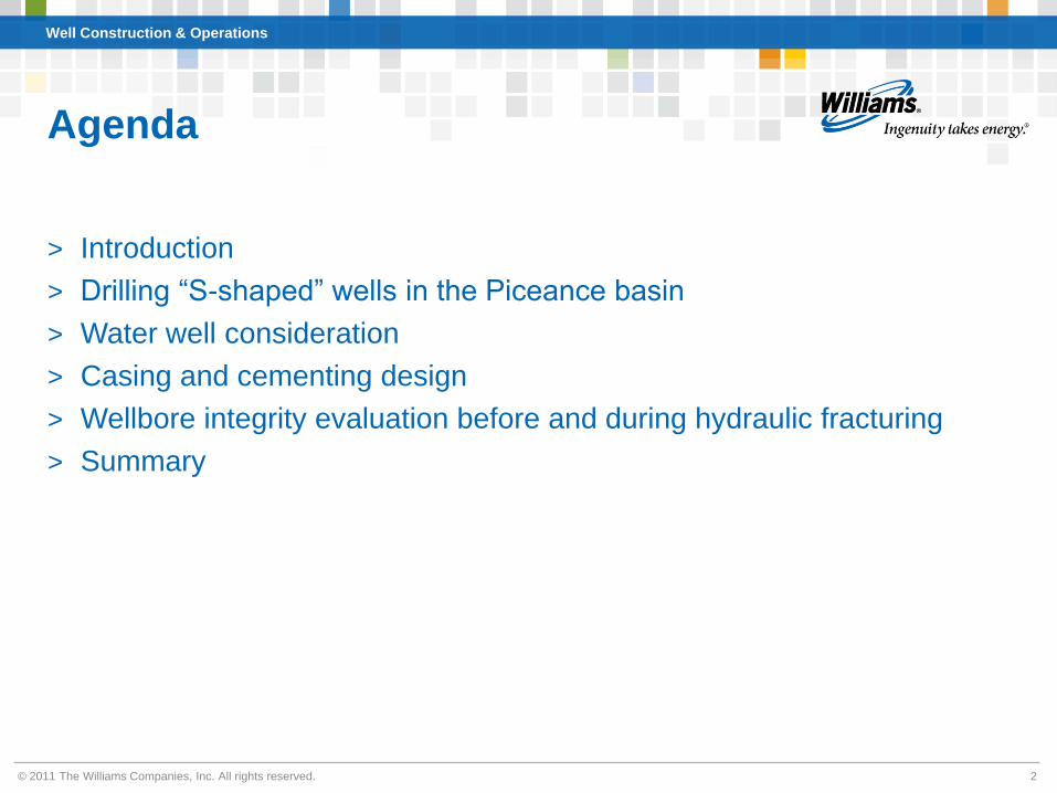
Agenda
> Introduction
> Drilling “S-shaped” wells in the Piceance basin
> Water well consideration
> Casing and cementing design
> Wellbore integrity evaluation before and during hydraulic fracturing
> Summary
© 2011 The Williams Companies, Inc. All rights reserved. 2

Williams’ Piceance Basin asset
Well Construction & Operations
© 2011 The Williams Companies, Inc. All rights reserved. 3

GRAND
HOGBACK
OUTCROP
Piceance Basin cross section
SOUTHWEST
NORTHEAST
Well Construction & Operations
COAL CANYON
OUTCROP
GAS
SATURATED
ZONE
TRANSITION ZONE
CAMEO +/- 1 mile
GRAND RULISON VALLEY
PARACHUTE
> Formations being hydraulically fractured are deep underground
> Drinking water is shallow in comparison
© 2011 The Williams Companies, Inc. All rights reserved.

shale sequence geology
requires vertical
penetration through gas
bearing zones
> Low permeability, small
sand bodies require 10
acre density to produce the
gas resource
© 2011 The Williams Companies, Inc. All rights reserved.
S-shaped, directional wells
> Stacked lenticular sand/
Well Construction & Operations
Water well zone
Gas bearing, “water free” target zones
5
Well Construction & Operations
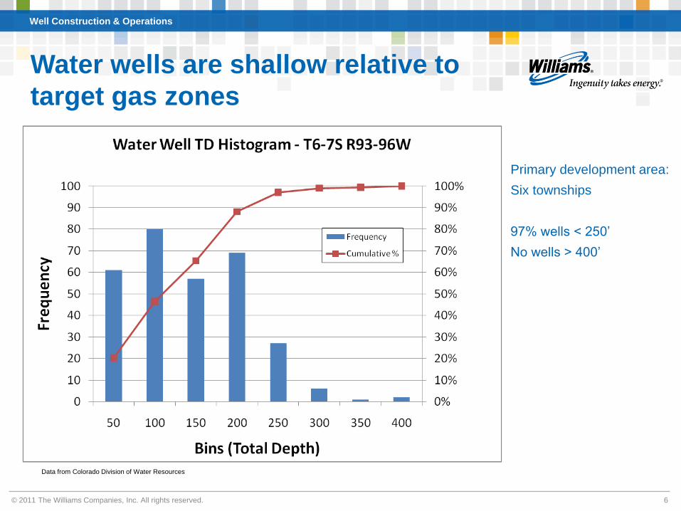
Water wells are shallow relative to
target gas zones
Primary development area:
Six townships
97% wells < 250’
No wells > 400’
Data from Colorado Division of Water Resources
© 2011 The Williams Companies, Inc. All rights reserved. 6

Well Construction & Operations
Cementing best practices - the result
of research and engineering
Centralizers push the casing toward the center Sample of solid cement filling the casing
of the hole and aid mud removal and annulus from a research project
cement placement around casing
7© 2011 The Williams Companies, Inc. All rights reserved.
© 2011 The Williams Companies, Inc. All rights reserved.
Well Construction & Operations
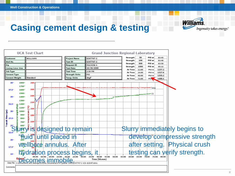
Casing cement design & testing
Slurry is designed to remain
“fluid” until placed in
wellbore annulus. After
hydration process begins, it
becomes immobile.
Slurry immediately begins to
develop compressive strength
after setting. Physical crush
testing can verify strength.
8
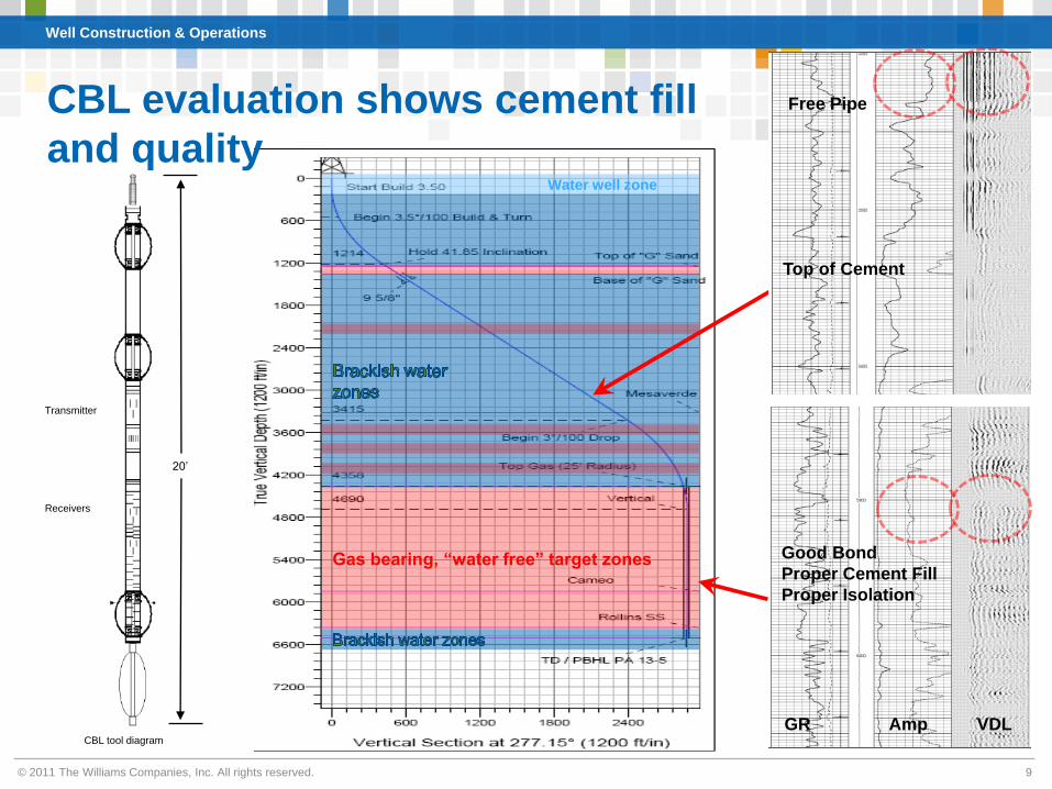
Water well zone
Gas bearing, “water free” target zones
CBL evaluation shows cement fill
and quality
Well Construction & Operations
GR Amp VDL
Top of Cement
Free Pipe
Good Bond
Proper Cement Fill
Proper Isolation
CBL tool diagram
Transmitter
Receivers
20’
© 2011 The Williams Companies, Inc. All rights reserved. 9
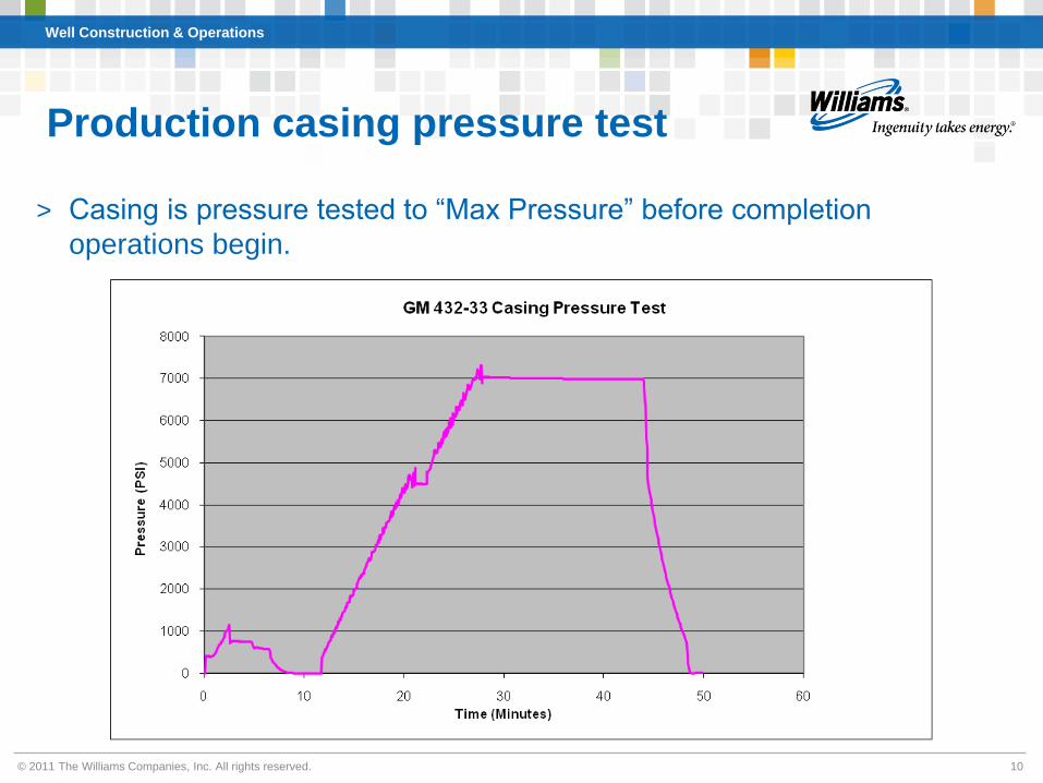
Production casing pressure test
Well Construction & Operations
> Casing is pressure tested to “Max Pressure” before completion
operations begin.
© 2011 The Williams Companies, Inc. All rights reserved. 10
Job Summary
-10
10
30
50
70
90
E
ion v4.0.0
:46
© 2011 The Williams Companies, Inc. All rights reserved.
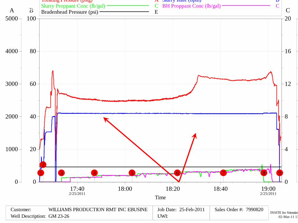
Production casing annulus pressure
monitoring
11
Annular space behind production casing is monitored for pressure
changes during frac treatments. If pressure communication occurs, the
job is shut down immediately and the problem remediated.
ion & Operations
Treating Pressure (psig) A Slurry Rate (bpm) B Slurry Proppant Conc (lb/gal) C BH Proppant Conc (lb/gal) C
A BWell Construct CBradenhead Pressure (psi) E
0
1000
2000
3000
4000
5000
0
20
40
60
80
100
0
4
8
12
16
20
9876543
2
1
17:40 18:00 18:20 18:40 19:00 2/25/2011 2/25/2011
Time
Customer: WILLIAMS PRODUCTION RMT INC EBUSINE Job Date: 25-Feb-2011 Sales Order #: 7990820
Well Description: GM 23-26 UWI: INSITE for Stimulat
02-Mar-11 13
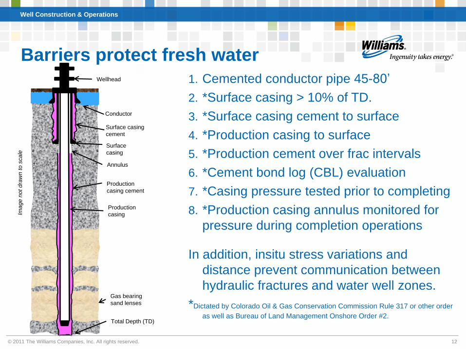
2. *Surface casing > 10% of TD. Conductor 3. *Surface casing cement to surface Surface casing
cement 4. *Production casing to surface Surface
casing 5. *Production cement over frac intervals Annulus
6. *Cement bond log (CBL) evaluation Production
casing cement 7. *Casing pressure tested prior to completing Production 8. *Production casing annulus monitored for casing
pressure during completion operations
In addition, insitu stress variations and
distance prevent communication between
hydraulic fractures and water well zones. Gas bearing
sand lenses *Dictated by Colorado Oil & Gas Conservation Commission Rule 317 or other order
as well as Bureau of Land Management Onshore Order #2. Total Depth (TD)
© 2011 The Williams Companies, Inc. All rights reserved.
Barriers protect fresh water
1. Cemented conductor pipe 45-80’Wellhead
Image n
ot dra
wn t
o s
cale
Well Construction & Operations
12
Well Construction & Operations
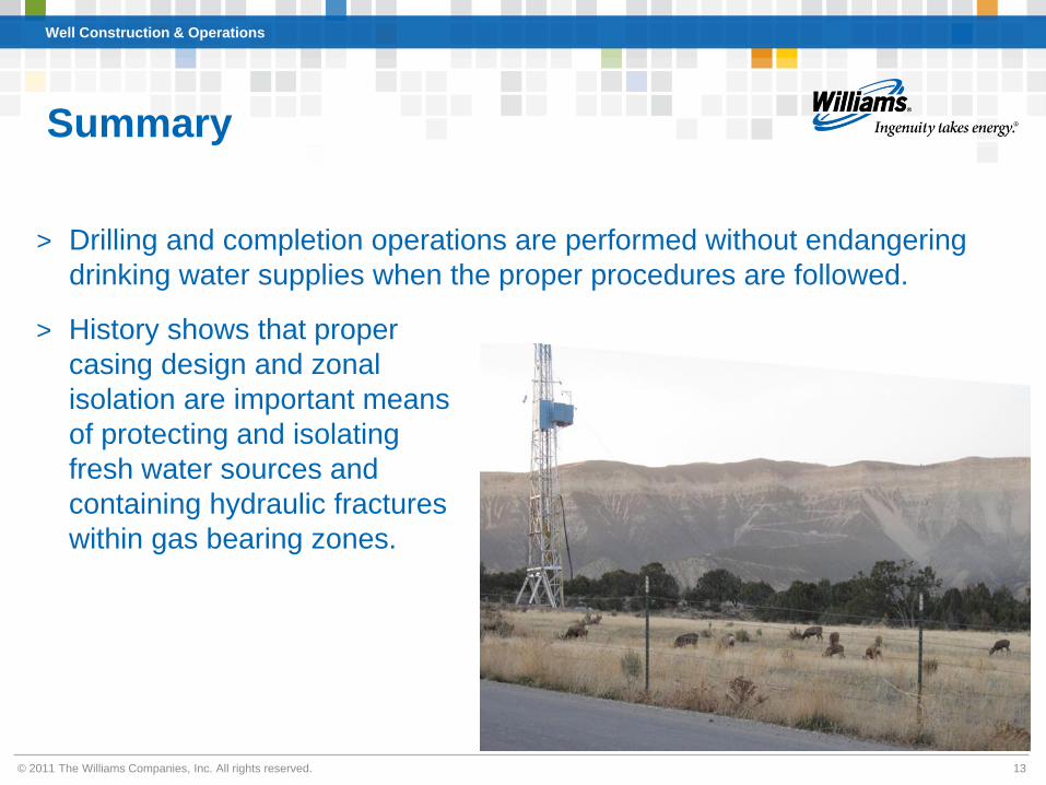
Summary
> Drilling and completion operations are performed without endangering
drinking water supplies when the proper procedures are followed.
> History shows that proper
casing design and zonal
isolation are important means
of protecting and isolating
fresh water sources and
containing hydraulic fractures
within gas bearing zones.
© 2011 The Williams Companies, Inc. All rights reserved. 13
Well Construction & Operations
Questions?
© 2011 The Williams Companies, Inc. All rights reserved. 14

Additional Slides
© 2011 The Williams Companies, Inc. All rights reserved. 15

Well Construction & Operations
S-shaped, directional wells
> Plan view of typical
pad
> Reach multiple
bottom-hole (BH)
locations from fewer
pads (up to 24, 10-
acre wells per pad).
> Typical target: 25’ radius cylinder
© 2011 The Williams Companies, Inc. All rights reserved. 16

Properly placed wells minimize waste
Well Construction & Operations
BH locations placed
based on stresses in
the earth which dictate
hydraulic fracture
orientation
> Minimize drainage
overlap
> Minimize un-drained
areas
Result:
> Efficient drainage of
independent reservoirs
> Less surface
disturbance
SHmax
Shmin
© 2011 The Williams Companies, Inc. All rights reserved. 17

Well Construction & Operations
Microseismic monitoring shows frac
containment within target zones
-1200
-1000
-800
-600
-400
-200
0
200
400
600
800
1000
1200
-1600 -1400 -1200 -1000 -800 -600 -400 -200 0 200 400 600 800
West-East (ft)
So
uth
-No
rth
(ft
)
533-33
543-33
SHmax
Shmin
5200
5300
5400
5500
5600
5700
5800
5900
-600 -500 -400 -300 -200 -100 0 100 200 300 400 500 600 700 800 900 1000 1100 1200 1300 1400
Distance Along Fracture (ft)
MD
(ft
)
Treatment well
perforations
Hydraulic fractures contained
within sand lenses
Plan view – frac azimuth is parallel
to the maximum horizontal
Side view of the same frac
treatment
stress © 2011 The Williams Companies, Inc. All rights reserved. 18

Total Column
12pt bold
Typical producing multi-well pad
Financial Outlook
Well Construction & Operations
© 2011 The Williams Companies, Inc. All rights reserved. 19

01.00.08
Multi-well Pad, Tight Gas, Directional Drilling Program Protects Aquifers Jay Foreman
Williams Production RMT
The statements made during the workshop do not represent the views or opinions of EPA. The claims made by participants have not been verified or endorsed by EPA.
Engineering and regulatory controls are in place in the oil & gas industry specifically in Colorado to ensure that completions operations for natural gas wells are conducted safely, cost effectively, and in an environmentally sound manner. This includes making sure that hydraulic fracture treatments go into and stay in the targeted zones where they will help stimulate oil or gas production. As a Completions Manager for the Piceance Asset, my job is to manage the engineering and operations activity required to turn a drilled well into one that produces natural gas safely and economically. Once a well is drilled, the casing is cemented in place and the drilling rig leaves the site. A completions engineer then examines the logs and specifics of the wellbore to design the perforating and stimulation procedures required to extract natural gas from subsurface rock strata. Since the reservoir rock is so impermeable, natural gas will not typically flow out of the reservoir at economic rates. Therefore, hydraulic fracturing (frac’ing) is required to “stimulate” the formation to produce natural gas. Proper well construction is critical to isolating the subterranean layers during completion and production operations. Not only is this important for keeping the frac treatments in the reservoir but for keeping unwanted water out of the gas zones. All aspects of drilling and completing wells are regulated by the Colorado Oil and Gas Conservation Commission (COGCC) and, if applicable, the Bureau of Land Management (BLM). In this document and the associated presentation given at the EPA’s Well Construction Operations Workshop, these two agencies’ regulations will be collectively referred to as State regulations. I will discuss well construction, cement design, and zonal isolation relative to our directional, multi-well pad development program on the Western Slope of Colorado. Water wells in the area are typically less than 250’ deep yet our surface casings are set at well below this depth with cement circulated to surface. Some pads have over 20 wells on 7-1/2’ centers so directional work begins as shallow as 100’.
Conductor pipe (+/-45’) and surface casings (>10% of the TD of the permitted well depth) are set before the production interval is drilled. The drilling mud in the annulus of the 9-5/8” diameter surface casing is displaced with cement engineered to meet State requirements. After the cement has cured and developed the required compressive strength, a smaller drill bit is used to drill out the bottom of the surface casing and drill the well to the permitted depth. Once a well is drilled and conditioned, the drill pipe is removed and 4-1/2” diameter production casing is run to the total depth (TD) of the well. At that point, the drilling mud in the hole is circulated for several hours to “condition” the hole and prepare it for cementing operations. Production casing of a specified grade and weight (wall thickness) is run such that its resulting burst pressure rating is greater than the anticipated operating pressures during the subsequent completion. Casing design is an area of engineering expertise and is addressed extensively by State regulations. The American Petroleum Institute has developed strict specifications for the manufacture of oilfield tubulars including casing. The design burst pressure of the casing string in a wellbore is duly noted by the operating company’s staff and contractors and the maximum allowable treating pressure (max pressure) is established and known by all who work on the well for the

01.00.08
remainder of its productive life. The pressure is not to be exceeded in order to protect the mechanical integrity of the wellbore.
The well is cemented with specially engineered cement with known density, thickening time, fluid loss, free water, and compressive strength. These parameters are based on bottom hole circulating and static temperatures and must meet State requirements. It is worth noting that manufacturing and testing specifications for completion cements are much more stringent than for cements used in construction projects. The API has established guidelines for all aspects of the cement and cementing operations to which operating and service companies adhere. The volume of cement pumped on the primary cement job is determined by isolation requirements for the zones to be completed as well as applicable State requirements for height of cement in the casing annulus. The cement is pumped down the casing and displaced with water behind a wiper plug. Once in place, the cement cures, getting hard and building compressive strength.
After the drilling rig leaves the well and sufficient time has passed to ensure proper cement compressive strength development, a cement bond log (CBL) is run to evaluate the quality and height of cement fill in the casing annulus. It is evaluated by the completions engineer to determine if the completion operations can be safely and effectively completed on the well. If not, the completion procedure will be altered to include remediation procedures to repair the primary cement job or to even exclude some zones from completion. In either case, the objective is to prevent undesirable communication between zones in the annulus.
Regulators are notified of the start of completions operations. The CBL is submitted to regulators prior to the first frac and any deficiencies with annular fill or cement bond quality are discussed. Calibrated pressure gauges are used to determine if pressure exists on the annulus of the production casing. If the annular pressure limit set by regulatory agencies is exceeded, they must be notified and remediation plans developed, sundried, approved, and executed.
The geologist and completions engineer evaluate the wireline logs to determine how the subsurface zones will be grouped together into frac stages, perforated and hydraulically fractured. The completion procedure is written, capturing critical information such as perforation depths, plug specifications and depths, frac job volumes, rates, proppant concentrations and volumes. All completion procedures note the casing specifications and the max pressure which is not to be exceeded. Treatments are engineered to minimize waste of materials while maximizing production. This can be based on fracture simulation programs and/or on field experience considering production results and the market costs of services and materials. Before any perforating begins, the production casing is pressure tested to the maximum allowable pressure. The test is recorded and submitted to the State. A well that fails the pressure test must be remediated in accordance with plans submitted to and approved by regulatory agencies.
The day of the first frac arrives and the frac crew gets the necessary equipment rigged up to the wellhead. Prior to any hydraulic fracturing treatment, all personnel on location are gathered for a prejob safety meeting where each person’s job responsibilities are reviewed. A headcount is taken and emergency egress procures are reviewed. These meetings even go so far as to designate a driver and note the closest medical facility in the unlikely event that someone is injured during the operation. During this meeting, it is clearly stated who is to “control” the job. One service company supervisor/ engineer and one company representative will be in complete control of the location during the job.

01.00.08
Max Pressure is discussed with all pump operators. Radio communication between all critical crew members is confirmed to ensure job control is maintained at all times.
Specifically engineered pressure gauges (typically 15,000 psi working pressure) and backup gauges are placed on the high pressure treating lines near the wellhead to monitor the treating pressure. Once every person is in their place, the high pressure pumps and lines (typically either 10,000 or 15,000 psi working pressure) are primed and pressure tested to the wellhead above max pressure for the job. Each pump has its own pressure gauge and “trip out” that is checked . This safety device will automatically shut the pump down if treating pressure exceeds the preset limit. A “global kickout” is also set on the control computer in the treatment control van where the two people in charge of the job can safely and comfortably monitor and control all aspects of the job. The global kickout will automatically shut down all pumps should treating pressure reach max pressure. The treatment design is programmed into the computer control system. All blending and pumping equipment on location can be run from the control van by the computer system or manually overridden as job requirements or well response determines.
Low pressure/ high accuracy pressure gauges are used to monitor the pressure on the annulus of the production casing during the treatment. Should annulus pressure rise beyond predetermined limits, the job will be aborted immediately and the situation evaluated. Regulators will be notified of any such event.
Once all safety systems are checked, the wellhead valves are opened and the pumping begins. A “pad” volume greater than wellbore volume is pumped at treating rate until the treating pressure stabilizes. At that point, the injection is stopped and an Instantaneous shut-in pressure (ISIP) reading is taken. Calculations are made from this wellhead pressure to determine how many perforations are open and accepting frac fluid. In addition, a formation frac gradient is calculated and compared to the anticipated frac gradient from the prejob simulation or experience in the area. If all perforations are open, the treatment proceeds. If not, the completion engineer may be consulted and the job can be redesigned if necessary.
During the remainder of the treatment, wellhead treating pressure, casing annulus pressure, and equipment performance are all closely monitored. While all are important, the most critical parameters are the actual wellhead treating pressure vs. anticipated treating pressure and max pressure. The pressure trends throughout the job give clues to what is occurring downhole. Dramatic increases in pressure may indicate that zones are “screening out” and no longer accepting fluid. Dramatic decreases in treating pressure may indicate an equipment problem either on surface or downhole. Subtle pressure changes can give clues to chemical performance as well as fracture growth in the formation. Should treating pressure rise and approach the Max Pressure, the two people in charge of the job will discuss and slow injection rate to reduce pipe and perforation friction and the resulting wellhead treating pressure. In some cases, rate changes in response to the well pressure are sufficient to allow the entire job design to be pumped and flushed. In other cases, the well “refuses” to accept the designed treatment and the job must be terminated early to prevent exceeding max pressure and damaging the wellbore or surface equipment.
01.00.08
Treatment placement can be validated in several ways.
The first is by monitoring the wellhead pressure during the treatment.
Secondly, the actual treating rates, pressures, and concentrations can be loaded back into the fracture design simulator. The simulator can then be “calibrated” to match the actual treatment data. Once a “good” match is obtained, the fracture dimensions of the simulation can be evaluated.
Thirdly, tracers can be run in the treatment and post-frac logs run to determine if unanticipated fracture height growth had occurred.
Lastly, microseismic monitoring from a nearby wellbore can give direct indication of the fracture height, length, and azimuth. With this service, arrays of sensitive geophones “listen” for the minute sounds of the hydraulic fracture growing through the reservoir rock. The location of these events can be calculated and plotted as dots on a three dimensional display. All the events recorded during the treatment are plotted vs. time for a representation of how the fracture grew throughout the treatment. These costly, non-routine monitoring projects are done for specific engineering purposes. The results can be used to further refine the fracture simulator and enhance the geologist’s and completion engineer’s general knowledge of fracture growth in the area.
Finally, the annulus pressure of the production casing is monitored during the treatment to ensure no communication occurs up the backside.
The plug/perf/frac process is repeated until all the frac stages are completed. The well is then cleaned out, production tubing landed, and the well is turned to production. The final analysis of the success or failure of the fracturing process comes from the production results.