Multi-tool and Multi-axis CNC Accumulation for Fabricating ...
22
Yong Chen. MANU-13-1120 1/22 Multi-tool and Multi-axis CNC Accumulation for Fabricating Conformal Features on Curved Surfaces Yayue Pan 1 , Chi Zhou 2 , Yong Chen 1 *, Jouni Partanen 3 1 Epstein Department of Industrial and Systems Engineering, University of Southern California, Los Angeles, CA 90089, U.S.A. 2 Department of Industrial and Systems Engineering, University at Buffalo, Amherst, NY 14260, U.S.A. 3 Department of Mechanical Engineering, Aalto University, Espoo, FI-00076 Aalto, Finland *Author of correspondence, Phone: (213) 740-7829, Fax: (213) 740-1120, Email: [email protected] Abstract In engineering systems, features such as textures or patterns on curved surfaces are common. In addition, such features, in many cases, are required to have shapes that are conformal to the underlying surfaces. To address the fabrication challenge in building such conformal features on curved surfaces, a newly developed additive manufacturing (AM) process named Computer Numerically Controlled (CNC) accumulation is investigated by integrating multiple tools and multiple axis motions. Based on a fiber optical cable and a light source, a CNC accumulation tool can have multi-axis motion, which is beneficial in building conformal features on curved surfaces. To address high resolution requirement, the use of multiple accumulation tools with different curing sizes, powers, and shapes is explored. The tool path planning methods for given cylindrical and spherical surfaces are discussed. Multiple test cases have been performed based on a developed prototype system. The experimental results illustrate the capability of the newly developed AM process and its potential use in fabricating conformal features on given curved surfaces. Keywords: Additive manufacturing, CNC accumulation, conformal structure, curved surface, tool path planning. 1. Introduction Additive manufacturing (AM), also known as layer manufacturing or solid freeform fabrication, is the process of joining materials to fabricate parts directly from CAD models. During the last twenty years, many novel AM processes such as Stereolithography (SLA), Selective Laser Sintering (SLS), and Fused Deposition Modeling (FDM) have been successfully commercialized. Recent advances in material, process and machine development have enabled AM processes evolving from prototyping usage (Rapid Prototyping) to product manufacturing (Rapid Manufacturing) [1]. Most current AM processes are layer-based by utilizing layer by layer deposition or lamination. While the uniform layers make the algorithm development, software coding, and hardware implementation simpler, it is usually accompanied by lowered surface quality. In addition, a built feature will have different material property depending on its building orientation, especially for small features whose sizes are close to the layer thickness. Figure 1a shows an example of a curved surface and conformal features on the surface. The given shape is first sliced into a set of two-dimensional (2D) layers. Accordingly a physical object is fabricated by stacking all the sliced 2D layers together. The fabricated features on the curved surface will have inconsistent size and shape, which may affect the desired material property. In addition, issues such as layer overcuring in the Z axis will pose severe limitations on the accuracy of the fabricated features.
-
Upload
nguyennhan -
Category
Documents
-
view
224 -
download
0
Transcript of Multi-tool and Multi-axis CNC Accumulation for Fabricating ...

Yong Chen. MANU-13-1120 1/22
Multi-tool and Multi-axis CNC Accumulation for Fabricating Conformal Features on Curved Surfaces
Yayue Pan1, Chi Zhou2, Yong Chen1*, Jouni Partanen3 1Epstein Department of Industrial and Systems Engineering, University of Southern California, Los
Angeles, CA 90089, U.S.A. 2Department of Industrial and Systems Engineering, University at Buffalo, Amherst, NY 14260, U.S.A.
3 Department of Mechanical Engineering, Aalto University, Espoo, FI-00076 Aalto, Finland *Author of correspondence, Phone: (213) 740-7829, Fax: (213) 740-1120, Email: [email protected]
Abstract In engineering systems, features such as textures or patterns on curved surfaces are common.
In addition, such features, in many cases, are required to have shapes that are conformal to the underlying surfaces. To address the fabrication challenge in building such conformal features on curved surfaces, a newly developed additive manufacturing (AM) process named Computer Numerically Controlled (CNC) accumulation is investigated by integrating multiple tools and multiple axis motions. Based on a fiber optical cable and a light source, a CNC accumulation tool can have multi-axis motion, which is beneficial in building conformal features on curved surfaces. To address high resolution requirement, the use of multiple accumulation tools with different curing sizes, powers, and shapes is explored. The tool path planning methods for given cylindrical and spherical surfaces are discussed. Multiple test cases have been performed based on a developed prototype system. The experimental results illustrate the capability of the newly developed AM process and its potential use in fabricating conformal features on given curved surfaces.
Keywords: Additive manufacturing, CNC accumulation, conformal structure, curved surface, tool path planning.
1. Introduction Additive manufacturing (AM), also known as layer manufacturing or solid freeform fabrication,
is the process of joining materials to fabricate parts directly from CAD models. During the last twenty years, many novel AM processes such as Stereolithography (SLA), Selective Laser Sintering (SLS), and Fused Deposition Modeling (FDM) have been successfully commercialized. Recent advances in material, process and machine development have enabled AM processes evolving from prototyping usage (Rapid Prototyping) to product manufacturing (Rapid Manufacturing) [1].
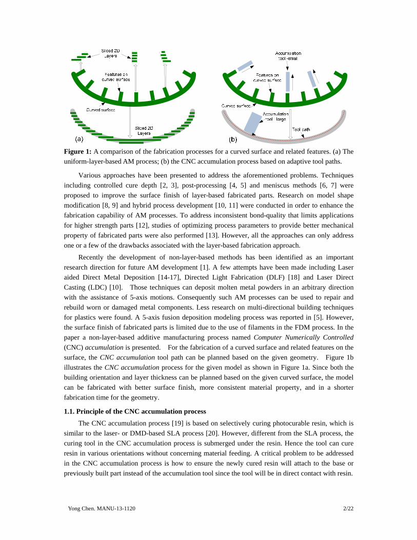
Most current AM processes are layer-based by utilizing layer by layer deposition or lamination. While the uniform layers make the algorithm development, software coding, and hardware implementation simpler, it is usually accompanied by lowered surface quality. In addition, a built feature will have different material property depending on its building orientation, especially for small features whose sizes are close to the layer thickness. Figure 1a shows an example of a curved surface and conformal features on the surface. The given shape is first sliced into a set of two-dimensional (2D) layers. Accordingly a physical object is fabricated by stacking all the sliced 2D layers together. The fabricated features on the curved surface will have inconsistent size and shape, which may affect the desired material property. In addition, issues such as layer overcuring in the Z axis will pose severe limitations on the accuracy of the fabricated features.
Yong Chen. MANU-13-1120 2/22
Figure 1: A comparison of the fabrication processes for a curved surface and related features. (a) The uniform-layer-based AM process; (b) the CNC accumulation process based on adaptive tool paths.
Various approaches have been presented to address the aforementioned problems. Techniques including controlled cure depth [2, 3], post-processing [4, 5] and meniscus methods [6, 7] were proposed to improve the surface finish of layer-based fabricated parts. Research on model shape modification [8, 9] and hybrid process development [10, 11] were conducted in order to enhance the fabrication capability of AM processes. To address inconsistent bond-quality that limits applications for higher strength parts [12], studies of optimizing process parameters to provide better mechanical property of fabricated parts were also performed [13]. However, all the approaches can only address one or a few of the drawbacks associated with the layer-based fabrication approach.
Recently the development of non-layer-based methods has been identified as an important research direction for future AM development [1]. A few attempts have been made including Laser aided Direct Metal Deposition [14-17], Directed Light Fabrication (DLF) [18] and Laser Direct Casting (LDC) [10]. Those techniques can deposit molten metal powders in an arbitrary direction with the assistance of 5-axis motions. Consequently such AM processes can be used to repair and rebuild worn or damaged metal components. Less research on multi-directional building techniques for plastics were found. A 5-axis fusion deposition modeling process was reported in [5]. However, the surface finish of fabricated parts is limited due to the use of filaments in the FDM process. In the paper a non-layer-based additive manufacturing process named Computer Numerically Controlled (CNC) accumulation is presented. For the fabrication of a curved surface and related features on the surface, the CNC accumulation tool path can be planned based on the given geometry. Figure 1b illustrates the CNC accumulation process for the given model as shown in Figure 1a. Since both the building orientation and layer thickness can be planned based on the given curved surface, the model can be fabricated with better surface finish, more consistent material property, and in a shorter fabrication time for the geometry.
1.1. Principle of the CNC accumulation process
The CNC accumulation process [19] is based on selectively curing photocurable resin, which is similar to the laser- or DMD-based SLA process [20]. However, different from the SLA process, the curing tool in the CNC accumulation process is submerged under the resin. Hence the tool can cure resin in various orientations without concerning material feeding. A critical problem to be addressed in the CNC accumulation process is how to ensure the newly cured resin will attach to the base or previously built part instead of the accumulation tool since the tool will be in direct contact with resin.
Yong Chen. MANU-13-1120 3/22
In our previous work [19], the relations between the cured shapes related to the input light energy were studied. The experimental results showed that the curing depth Cd is proportional to the logarithm of the exposure energy. The attaching forces in the CNC accumulation process were also studied. Based on curing equations and designed experiments, the attaching forces related to a set of process parameters were modeled. In order to ensure the cured resin can be safely detached from the tool, the relations between the attaching force and different types of surfaces including fiber optical, plastic film, Teflon film and cured resin were studied. Among them, the best detaching performance is achieved based on:
(1) Applying a coating of Teflon film on the tip of the curing tool such that the attaching force between the resin and the tool can be reduced;
(2) Ensuring adequate resin overcure such that the attaching force between the newly cured resin and the base or the previously built part can be sufficiently large.
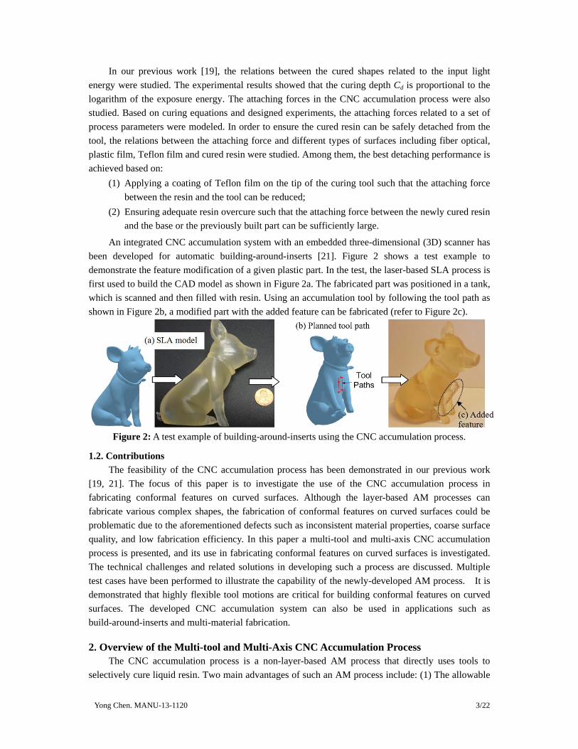
An integrated CNC accumulation system with an embedded three-dimensional (3D) scanner has been developed for automatic building-around-inserts [21]. Figure 2 shows a test example to demonstrate the feature modification of a given plastic part. In the test, the laser-based SLA process is first used to build the CAD model as shown in Figure 2a. The fabricated part was positioned in a tank, which is scanned and then filled with resin. Using an accumulation tool by following the tool path as shown in Figure 2b, a modified part with the added feature can be fabricated (refer to Figure 2c).
Figure 2: A test example of building-around-inserts using the CNC accumulation process.
1.2. Contributions The feasibility of the CNC accumulation process has been demonstrated in our previous work
[19, 21]. The focus of this paper is to investigate the use of the CNC accumulation process in fabricating conformal features on curved surfaces. Although the layer-based AM processes can fabricate various complex shapes, the fabrication of conformal features on curved surfaces could be problematic due to the aforementioned defects such as inconsistent material properties, coarse surface quality, and low fabrication efficiency. In this paper a multi-tool and multi-axis CNC accumulation process is presented, and its use in fabricating conformal features on curved surfaces is investigated. The technical challenges and related solutions in developing such a process are discussed. Multiple test cases have been performed to illustrate the capability of the newly-developed AM process. It is demonstrated that highly flexible tool motions are critical for building conformal features on curved surfaces. The developed CNC accumulation system can also be used in applications such as build-around-inserts and multi-material fabrication.
2. Overview of the Multi-tool and Multi-Axis CNC Accumulation Process The CNC accumulation process is a non-layer-based AM process that directly uses tools to
selectively cure liquid resin. Two main advantages of such an AM process include: (1) The allowable

Yong Chen. MANU-13-1120 4/22
motions between the tool and the work piece are significantly increased; and (2) the feeding of liquid resin is straightforward since the tool is submerged under the resin. In order to fabricate conformal features on curved surfaces, the use of multiple tools and multi-axis motions are investigated in the CNC accumulation process.
(1) Multiple tools. A single accumulation tool was used in our previous work [19]. The light spot size of the tool is ~1.57mm. Such a resolution is usually insufficient for fabricating fine features on curved surfaces. Motivated by the commonly used multi-tool stations in CNC machines [22-24], alternative accumulation tools with higher resolution and in various shapes are investigated in this paper. Accordingly a CNC accumulation system with multiple tools has been developed. The tool path planning based on multiple accumulation tools are also discussed for building features with varying resolutions in a single component.
(2) Multi-axis tool motion: In addition to translational motions in the X, Y, and Z axes that are commonly used in the layer-based AM processes, the tools in the CNC accumulation process can have multiple rotational motions as well. Inspired by the multi-axis CNC machining process, the tool path planning for building features on curved surfaces such as cylindrical and spherical surfaces is investigated. The desired tool motion is required to consider both built features and the underlying surface in order to achieve desired shapes.
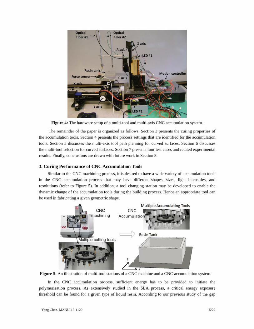
Figure 3 shows a schematic illustration of a multi-tool and multi-axis CNC accumulation system. A photo of the developed prototype system is shown in Figure 4. In the system, two sets of accumulative tools are used to demonstrate the multi-tool station concept. The ultraviolet (UV) LED of the larger tool is from Nichia (NCSU033A). A sapphire ball lenses (NT43-831 from Edmunds Optics) is used to focus light on a quartz fiber optic light guide (NT38-954 from Edmunds Optics). The spot size of the provided ultraviolet (UV) light has a similar size to the core size of the optical fiber, which is 1.57mm. The UV-LED used in the smaller tool is from Mightex System (FCS-0365-000). The optical fiber is also from Mightex System (FPC-0200-22-02SMA). The core size of the optical fiber is much smaller (~0.3mm or 300μm). A Teflon film is applied on the tip of both tools. A 5-axis motion system is designed to allow the accumulation tools to be able to provide UV light in various orientations. The 5-axis motion includes the X, Y, Z translations and the A, C rotations. The X, Y, and C motions are applied to the workpiece while the other two are applied to the tool. Using the setup, multiple test cases have been performed to illustrate the capability of the CNC accumulation process in fabricating conformal features on curved surfaces.
C
A
Figure 3: A schematic illustration of the multi-tool and multi-axis CNC accumulation process.
Yong Chen. MANU-13-1120 5/22
Figure 4: The hardware setup of a multi-tool and multi-axis CNC accumulation system.
The remainder of the paper is organized as follows. Section 3 presents the curing properties of the accumulation tools. Section 4 presents the process settings that are identified for the accumulation tools. Section 5 discusses the multi-axis tool path planning for curved surfaces. Section 6 discusses the multi-tool selection for curved surfaces. Section 7 presents four test cases and related experimental results. Finally, conclusions are drawn with future work in Section 8.
3. Curing Performance of CNC Accumulation Tools Similar to the CNC machining process, it is desired to have a wide variety of accumulation tools
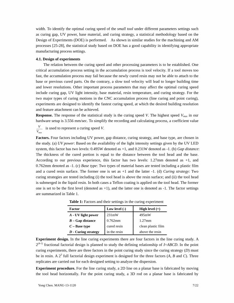
in the CNC accumulation process that may have different shapes, sizes, light intensities, and resolutions (refer to Figure 5). In addition, a tool changing station may be developed to enable the dynamic change of the accumulation tools during the building process. Hence an appropriate tool can be used in fabricating a given geometric shape.
Figure 5: An illustration of multi-tool stations of a CNC machine and a CNC accumulation system.
In the CNC accumulation process, sufficient energy has to be provided to initiate the polymerization process. As extensively studied in the SLA process, a critical energy exposure threshold can be found for a given type of liquid resin. According to our previous study of the gap

Yong Chen. MANU-13-1120 6/22
between the tool and the built part, a specific gap as well as the curing depth can be identified based on the critical energy [19]. For fixed curing depth and penetration depth, the curing width is
proportional to the spot diameter ( 2w d pL B C D= ). Thus, a highly focused UV spot can cure a
feature with high resolution while a tool with a much larger spot can cure a large area with an increased building speed. A single tool with a spot diameter around 2mm was used in our previous work [19]. In this study, a second tool is added with a spot diameter of 0.3mm. In the paper they are named large tool and small tool respectively. By integrating the two accumulation tools in the system, a good balance between the building resolution and fabrication speed can be achieved.
The curing performances of the two accumulation tools based on the aforementioned UV LEDs and fiber cables are measured and compared. For a photocurable resin (Accura 60 from 3D Systems), a set of experiments have been conducted to model the curing performance of the accumulation tools.
Figure 6 shows the relation between curing depth and curing time for the point curing case (i.e. the curing tool is moving in the curing direction [19]). As shown in the figure, the fitted curves are close to the polymerization equations for both tools. In addition, for the same exposure time, the small tool will always cure deeper than the large tool. Results also indicate that the cured shape by using the small tool has a smaller size than the large tool.
Figure 6: The relation between curing depth and exposure time for the accumulation tools.
Figure 7: The relation between curing width and motion speed for the accumulation tools.
Figure 7 shows the relation between curing width and curing speed for the line curing case (i.e. the curing tool is moving in a direction that is orthogonal to the curing direction [19]). As shown in the figure, the large tool has much larger curing width than the small tool for the same motion speed. When the curing speed is fast (>0.75 mm/s), nothing will be cured by using the large tool while the small tool can still cure lines with a high resolution. Based on our experiments, the minimum line width (i.e. lateral resolution) that can be achieved by the small and big tools is around 0.2mm and 1.5mm respectively.
4. Process Settings of Multi-tool CNC Accumulation System The process settings of the large tool have been studied based on trial-and-errors in [19].
However, the resolution of the large tool is much lower than that of the small tool. As shown in Figures 6 and 7, the small tool has a higher motion velocity, a bigger curing depth and a smaller line
Yong Chen. MANU-13-1120 7/22
width. To identify the optimal curing speed of the small tool under different parameters settings such as curing gap, UV power, base material, and curing strategy, a statistical methodology based on the Design of Experiments (DOE) is performed. As shown in similar studies for the machining and AM processes [25-28], the statistical study based on DOE has a good capability in identifying appropriate manufacturing process settings.
4.1. Design of experiments The relation between the curing speed and other processing parameters is to be established. One
critical accumulation process setting in the accumulation process is tool velocity. If a tool moves too fast, the accumulation process may fail because the newly cured resin may not be able to attach to the base or previous cured parts. On the contrary, a slow tool velocity will lead to longer building time and lower resolutions. Other important process parameters that may affect the optimal curing speed include curing gap, UV light intensity, base material, resin temperature, and curing strategy. For the two major types of curing motions in the CNC accumulation process (line curing and point curing), experiments are designed to identify the fastest curing speed, at which the desired building resolution and feature attachment can be achieved. Response. The response of the statistical study is the curing speed V. The highest speed Vmax in our hardware setup is 3.556 mm/sec. To simplify the recording and calculating process, a coefficient value
max
VV
is used to represent a curing speed V.
Factors. Four factors including UV power, gap distance, curing strategy, and base type, are chosen in the study. (a) UV power: Based on the availability of the light intensity settings given by the UV LED system, this factor has two levels: 0.495W denoted as +1, and 0.231W denoted as -1. (b) Gap distance: The thickness of the cured portion is equal to the distance between the tool head and the base. According to our previous experience, this factor has two levels: 1.27mm denoted as +1, and 0.762mm denoted as -1. (c) Base type: Two types of material bases are tested including a plastic film and a cured resin surface. The former one is set as +1 and the latter -1. (d) Curing strategy: Two curing strategies are tested including (i) the tool head is above the resin surface; and (ii) the tool head is submerged in the liquid resin. In both cases a Teflon coating is applied on the tool head. The former one is set to be the first level (denoted as +1), and the latter one is denoted as -1. The factor settings are summarized in Table 1.
Table 1: Factors and their settings in the curing experiment
Factor Low level (-) High level (+)
A - UV light power 231mW 495mW B – Gap distance 0.762mm 1.27mm C – Base type cured resin clean plastic film D - Curing strategy in the resin above the resin
Experiment design. In the line curing experiments there are four factors in the line curing study. A 2(4-1) fractional factorial design is planned to study the defining relationship of I=ABCD. In the point curing experiments, there are three factors in the point curing study since the curing strategy (D) must be in resin. A 23 full factorial design experiment is designed for the three factors (A, B and C). Three replicates are carried out for each designed setting to analyze the dispersion.
Experiment procedure. For the line curing study, a 2D line on a planar base is fabricated by moving the tool head horizontally. For the point curing study, a 3D rod on a planar base is fabricated by
Yong Chen. MANU-13-1120 8/22
moving the tool head along the normal of the base surface. For each given parameter setting, experiments are performed by slightly varying the curing speed V. For each tested speed, ten replicated experiments are performed. The maximum speed is identified such that the related curing line resolution is less than 0.3mm and the success rate is larger than 80% (i.e. eight or more results satisfy the given requirements).
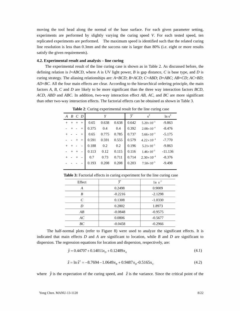
4.2. Experimental result and analysis – line curing The experimental result of the line curing case is shown as in Table 2. As discussed before, the
defining relation is I=ABCD, where A is UV light power, B is gap distance, C is base type, and D is curing strategy. The aliasing relationships are: A=BCD; B=ACD; C=ABD; D=ABC; AB=CD; AC=BD; AD=BC. All the four main effects are clear. According to the hierarchical ordering principle, the main factors A, B, C and D are likely to be more significant than the three way interaction factors BCD, ACD, ABD and ABC. In addition, two-way interaction effect AB, AC, and BC are more significant than other two-way interaction effects. The factorial effects can be obtained as shown in Table 3.
Table 2: Curing experimental result for the line curing case
A B C D Y y s2 ln s2
+ + + + 0.65 0.638 0.638 0.642 55.20 10−× -9.863 - + - + 0.375 0.4 0.4 0.392 42.08 10−× -8.476 + - - + 0.65 0.775 0.785 0.737 35.66 10−× -5.175 - - + + 0.591 0.591 0.555 0.579 44.22 10−× -7.770 + + - - 0.188 0.2 0.2 0.196 55.21 10−× -9.863 - + + - 0.113 0.12 0.115 0.116 51.46 10−× -11.136 + - + - 0.7 0.73 0.711 0.714 42.30 10−× -8.376 - - - - 0.193 0.208 0.208 0.203 57.50 10−× -9.498
Table 3: Factorial effects in curing experiment for the line curing case
Effect y 2ln sA 0.2498 0.9009 B -0.2216 -2.1298 C 0.1308 -1.0330 D 0.2802 1.8973 AB -0.0848 -0.9575 AC 0.0806 -0.5677 BC -0.0458 -0.2966
The half-normal plots (refer to Figure 8) were used to analyze the significant effects. It is indicated that main effects D and A are significant to location, while B and D are significant to dispersion. The regression equations for location and dispersion, respectively, are:
ˆ 0.44707 0.14011 0.12489D Ay x x= + + (4.1)
2ˆˆ ln 8.7694 1.0649 0.9487 -0.5165x B D Cz s x x= = − − + (4.2)
where y is the expectation of the curing speed, and z is the variance. Since the critical point of the

Yong Chen. MANU-13-1120 9/22
optimal speed is identified as the largest feasible speed, it can be considered as a Larger-the-Better problem. Consequently both +1 levels for A and D are chosen to maximize the average expected optimal velocity E(y), and B and C are set to +1 as well to minimize the variance of optimal velocity Var(y). Thus the optimal setting for the line curing case should be (+,+,+,+), which means that light power is 495mW, gap size is the big level 1.27mm, the base material is a plastic film, and the tool is above the liquid resin surface. The corresponding curing speed is 2.53mm/s.
Figure 8: Half-normal plots of the curing experiment for the line curing case.
4.3. Experimental results and analysis – point curing The experimental result of the point curing case is shown in Table 4. The factorial effects and
related half-normal plots are shown in Table 5 and Figure 9 respectively.
Table 4: Curing experiment for the point curing case
A B C Y y s2 ln s2
+ + + 0.145 0.18 0.18 0.168 44.08 10−× -7.803 + + - 0.132 0.127 0.125 0.128 51.36 10−× -11.207 - + + 0.05 0.053 0.056 0.053 67.58 10−× -11.790 - + - 0.065 0.06 0.069 0.065 51.83 10−× -10.911 + - + 0.15 0.18 0.15 0.160 43.00 10−× -8.112 + - - 0.12 0.130 0.12 0.123 53.01 10−× -10.412 - - + 0.114 0.1 0.09 0.101 41.45 10−× -8.837 - - - 0.102 0.1 0.1 0.101 77.50 10−× -14.103
Table 5: Factorial effects in curing experiment for the point curing case
Effect y 2ln s
A 0.0650 2.0268 B -0.0179 -0.0620 C 0.0166 2.5229
AB 0.0243 -0.1814 AC 0.0220 0.3286 BC -0.0022 -1.2604
ABC 0.0040 1.8121
It is shown that A and AB are significant location effects, and C and A are significant dispersion effects. The regression equations for location and dispersion are given as follows:
Yong Chen. MANU-13-1120 10/22
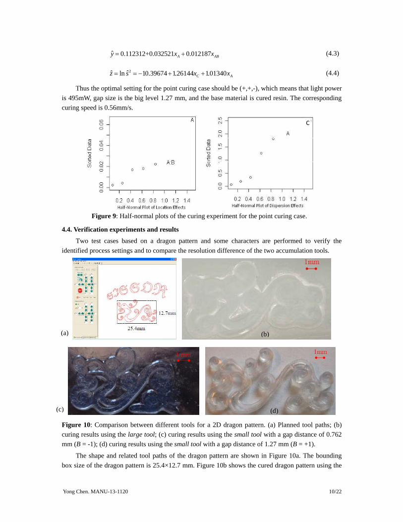
ˆ 0.112312+0.032521 0.012187A ABy x x= + (4.3)
2ˆˆ ln 10.39674 1.26144 1.01340C Az s x x= = − + + (4.4)
Thus the optimal setting for the point curing case should be (+,+,-), which means that light power is 495mW, gap size is the big level 1.27 mm, and the base material is cured resin. The corresponding curing speed is 0.56mm/s.
C
Figure 9: Half-normal plots of the curing experiment for the point curing case.
4.4. Verification experiments and results
Two test cases based on a dragon pattern and some characters are performed to verify the identified process settings and to compare the resolution difference of the two accumulation tools.
Figure 10: Comparison between different tools for a 2D dragon pattern. (a) Planned tool paths; (b) curing results using the large tool; (c) curing results using the small tool with a gap distance of 0.762 mm (B = -1); (d) curing results using the small tool with a gap distance of 1.27 mm (B = +1).
The shape and related tool paths of the dragon pattern are shown in Figure 10a. The bounding box size of the dragon pattern is 25.4×12.7 mm. Figure 10b shows the cured dragon pattern using the
1 mm
(a) (b)
(c) (d)

Yong Chen. MANU-13-1120 11/22
large tool. Figure 10c shows the cured dragon pattern using the small tool with the settings of (+,−,+,+), in which the gap size is 0.762 mm (B=-1). In comparison, Figure 10d shows the cured dragon pattern using the small tool with the optimal setting identified in the statistical study (+,+,+,+). The testing results verified that using the small tool with the optimal setting identified in the statistical study can lead to a building resolution that is less than 300μm. The shape and related tool paths of the characters are also shown in Figure 10a. Figure 11a shows the cured characters using the large tool. In comparison, Figure 11b shows the cured pattern using the small tool from the same tool paths. The results demonstrate that the small tool can achieve a much clearer outline than the large tool.
Figure 11: Comparison between different tools for given characters. (a) curing results of the characters using the large tool; (b) curing results of the characters using the small tool.
5. Motion Planning for Building Features on Curved Surfaces Extensive work has been done on tool path planning for CNC machining (e.g. [29]). In
comparison, few attempts have been made on multi-axis tool path planning for additive manufacturing processes. In a work done by Sundaram and Choi [30], a direct slicing procedure for the 5-axis Laser-aided Metal Deposition process is presented. A neutral exchange format IGES was used as the slicing format. The SURFCAM system developed for 3- to 5-axis milling process was customized for the material deposition operation. An adaptive slicing method for the multi-axis Laser-aided Manufacturing Process (LAMP) was investigated in [11, 31]. A software system was developed using Visual C++ and OpenGL and integrated with their hardware system. The slicing direction can change with the surface curvature of the part. The layer thickness can also be changed to make the overhang of all adjacent layers be within the maximum overhang range. Thus the sliced part can be built without any support structure. The aforementioned multi-axis tool path planning methods are all designed for the metal-based AM processes. In addition, only a single tool was considered in the studies. For the purpose of building conformal features on curved surfaces, the tool motion and building process of the multi-tool and multi-axis CNC accumulative process are discussed as follows.
5.1. Tool motion for different curved surfaces
In order to achieve a better lateral resolution and accuracy, it is generally desired to plan the circular path by using rotation motion instead of the interpolation of X-Y translations as illustrated in the 5-axis CNC machining process [32, 33]. For a given curved surface especially cylindrical and spherical surfaces, a five-axis motion including three translations along the X, Y, Z axis and two rotations A and C around the X and Z axes can be utilized.
Figure 12a shows the 5-axis motion configuration incorporated in our CNC accumulation system. In addition to the X, Y, Z translations, the rotations C is used for controlling the tools to scan around spherical or cylindrical surface; and the rotation A is used to position the tool to the normal direction of a curved surface. Consequently, a desired surface quality and material consistency can be
(b) (a)

Yong Chen. MANU-13-1120 12/22
achieved by such a 5-axis CNC accumulation process. To simplify the tool path planning problem, a coordinate system is constructed with three constraints including: (i) the rotation centers O1 and O2 are aligned on the same height along the Z axis; (ii) the tool is aligned to be parallel to the Z axis; and (iii) the tool is pointing to the rotation center O1.
Y
Z
X
R2
R2
R1
R1
Z
X
Y
Tool head
T2
T1
Θ
C
A
Z
Y X
T1
T2
Θ
A
Z
YX
T1
T2 T3
Θ
C
A
Tool head
T1
T2
Z
YX
Figure 12: A schematic illustration of the 5-axis motion configuration for curved surfaces. (a) 5-axis motion configuration; (b) a surface with curvatures R1 and R2 in the X and Y axes; (c) feature fabrication on a flat surface with the X, Y, and Z translations; (d) feature fabrication on a cylindrical surface with the Y, Z, A, and C motions; (e) feature fabrication on a cylindrical surface with the X, Y, Z, and A motions; (f) feature fabrication on a spherical surface with the Y, Z, A, and C motions.
As shown in Figure 12b, an arbitrary curved surface could be described by two radiuses of curvatures at a given point, R1 and R2. In this paper, three types of surfaces (flat, cylindrical, and spherical surfaces) are considered.
(1) Flat surface: When R1 and R2 are both infinite, the surface is flat. Figure 12c presents an illustration of fabricating features on a flat surface. In the figure, the blue color lines represent the cured resin on a base surface; and a gray block denotes the tool head. Accordingly, the material curing path direction is denoted as T2, which is an interpolation of the X and Y axis motions. The material accumulation direction is denoted as T1, which can be achieved by the Z axis motion. Thus the tool path planning for the flat surface case is the same as conventional AM processes based on the translations along the X, Y and Z axes.
(2) Cylindrical surface: When one of the curvatures is infinite and another one is finite, the curved surface is a cylindrical surface. Two different types of cylindrical surfaces are shown in Figure 12d and 12e. To fabricate conformal features on such surfaces, multiple axis movements including rotations are required. In both cases, the tool needs to be tilted by θ degree using the rotation A such that it can be aligned to the normal direction of the cylindrical surface. Thus the material accumulation process can be facilitated either along the accumulation direction T1, or along the curing directions T2 and T3. For the cylindrical surface as shown in Figure 12d, the Y and Z
(a) (b) (c)
(d) (e) (f)

Yong Chen. MANU-13-1120 13/22
translations are combined to define T1 and T2. In addition, the C rotation is used for curing around the cylindrical surface. For the cylindrical surface as shown in Figure 12e, the Y, Z translations are combined to define T1. The X translation is used to define the curing path T2 along the cylindrical surface.
(3) Spherical surface: When both curvatures R1 and R2 are finite and equivalent, the surface is a spherical surface. For fabricating features on a spherical surface, the rotation A is used to position the tool in the normal direction of the spherical surface. As shown in Figure 12f, the accumulation direction T1 and the curing directions T2 can be defined by combining the A, C rotations with the Y, Z translations.
5.2. Building process for features on a spherical surface
As a cylindrical surface can be viewed as a special case of a spherical surface by setting one dimensional curvature as infinite, its tool path planning can be derived from the more general case of a spherical surface. The building of features on a spherical surface is discussed as follows.
ΘTool head
1st layer
5th layer
Base
R
d
l
a
DA
Z
XYC
Figure 13: An example of building features on a spherical surface.
Figure 13 shows an example in which a set of rods are fabricated on a spherical surface. In the multi-tool CNC accumulation process, the large tool is first used in building the base spherical surface. After the base surface has been built, the small tool can then be used in building the rods on the surface. A description of the building process based on both tools is given as follows.
1. Initialize the position for the large tool and the motion for 5 axes; 2. Rotate the tool (Rotation A) by θ to point the tool in the normal direction of the spherical
surface; 3. Turn on the UV LED of the large tool; 4. Rotate the platform (Rotation C) by one full round; 5. Turn off the UV LED of the large tool; 6. Go to 2 if the base surface is not finished, otherwise go to 7; 7. Initialize the position for the small tool; 8. Control the motion back to the home position; 9. Rotate the small tool (Rotation A) by θ to point the tool in the normal direction of the
spherical surface; 10. Rotate the platform (Rotation C) by β , which is determined by the adjacent rods at the
height related to d; 11. Turn on the UV LED of the small tool; 12. Move the small tool in the normal direction of the spherical surface (using the Y-Z
translations).
(a) (b)
Yong Chen. MANU-13-1120 14/22
13. Turn off the UV LED of the small tool if the rod is finished. 14. Go to 10 if not all the rods in the same Z level are finished; otherwise, go to 9 if not all of the
rods are finished; 15. Stop the building process when all the rods have been built. For a given test case and the related CNC accumulative process, the design and manufacturing
parameters and their constraints can be identified as follows. (1) Identifying design parameters:
θ : the A rotation angle between two neighboring rods; d : the distance between two neighboring rods;
iθ : the A rotation angle between the bottom with the rods in the ith round;
iβ : the C rotation angle between two neighboring rods in the ith round; N : the number of rounds.
(2) Identifying manufacturing parameters: D : diameter of the tool head; R : radius of the spherical base; a : diameter of the rod; l : height of the rod; Ψ : the maximum rotation angle that the tool can achieve.
(3) Parameter constraints: Some constraints may exist due to the tool and part collision and the hardware setup. For example, the tool head may collide the neighboring pillars if θ is too small. Hence the minimum value of θ can be derived based on D , a , R and l. As another example, suppose Ψ is the maximum angle that the tool head can be rotated. Accordingly the maximum number of rounds (N) will be limited by Ψ . A list of such constraints on the aforementioned parameters is given as follows.
(i) 1 1
2 2
2tan sin2( ) 4( )
a DR l a R l
θ − −⎛ ⎞⎛ ⎞ ⎜ ⎟≥ +⎜ ⎟ ⎜ ⎟−⎝ ⎠ + −⎝ ⎠
; (ii) i i i d Rθ θ= ∗ = ∗ ;
(iii) 2 sin( )i in R dπ α= ∗⎢ ⎥⎣ ⎦ ; (iv) 2i inβ π= ; and (v) N θ≤ Ψ⎢ ⎥⎣ ⎦ .
With some adjustments, the parameters and constraints can also be applied to features on other curved surfaces. For example, to fabricate a dragon pattern on a spherical surface, the pattern can be decomposed into multiple layers on the surface. The parameter a and θ can vary in different layers and be combined with the Y, Z motions to define a set of close loops. Note l would not be a constant for each layer. Similarly, the building process can be extended to fabricate other types of features on a spherical or a cylindrical surface.
6. Tool Selection for Building Features on a Curved Surface
6.1. Selection of a straight accumulation tool For an accumulation tool that has a cylindrical shape with a diameter dt, two types of collision
may exist in the fabrication process. In the first case (refer to Figure 14a), a tool may be too big to
reach a curing depth cd in a curved surface with a curvature rs (i.e. 0 12td P P≤ ). In the second case
(refer to Figure 14b), a tool may be too big for a rotating angle θ related to a curved surface (i.e.
2 3OP OP≤ ).

Yong Chen. MANU-13-1120 15/22
The tool size based on the related constraints can be derived as:
2 (2 )t d s dd c r c≤ × − , and (6.1)
2( ) sint s dd r c θ≤ − × ; (6.2)
where dt is the diameter of the tool, rs is the smallest surface curvatures in all dimensions, and cd is the curing depth. Therefore, for fabricating features on a given cylindrical and spherical surface with given surface curvature, the tool size dt can be selected by setting the related rs in the equations.
Tool head
P0P1
O
cd
dt rs
θ
O
P3P2
rs
dt
Figure 14: An illustration of the relationship between tool size and surface curvatures: (a) Tool size dt constrained by curvature rs; (b) Tool size dt constrained by curvature rs and rotation angle θ.
6.2. Test of an angled tool for fabricating features on a vertical surface Materials can be accumulated in a variety of directions with the aid of tool rotations. However,
the feasible rotation angle θmax is limited for a straight tool as shown in the previous section. In order to build features on a surface that requires a large rotation angle (e.g. a vertical surface), a non-straight accumulation tool can be used in the fabrication process. As shown in Figure 15a, an angled accumulative tool was made for testing in our multi-tool and multi-axis CNC accumulation system. Similar to the straight tools as discussed before, the angled accumulation tool is also made of a fiber optics guide with a Teflon film coating. The only difference is that the tool head is bent by a certain angle (e.g. 45o).
Fixture
Coating
Optic Fibers
Z
X
Y
Figure 15: Test of an angled tool on repairing a feature on a vertical wall. (a) Tool head with coating; (b) physical model before repair; (c) planned tool path; (d) physical model after repair.
A test case of repairing a slot on a vertical surface is performed to illustrate the capability of the CNC accumulation process on building features along the Y axis. Such accumulation process would be impossible for a straight tool as shown in Figure 4. In the test, a physical model is first built by a commercial SLA machine (refer to Figure 15b). The built cube has four slots on one side. Suppose the bottom one needs to be enclosed. The planned tool path based on the X and Y axis motions is shown in Figure 15c. The built physical model is shown in Figure 15d. Hence angled accumulation tools can enable building features on curved surfaces that are vertical or even facing downwards.
(a) (b) (c)(d)
(b) (a)
Yong Chen. MANU-13-1120 16/22
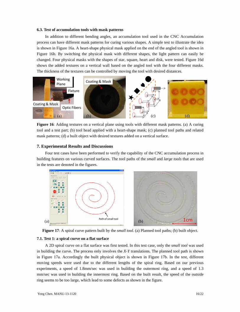
6.3. Test of accumulation tools with mask patterns
In addition to different bending angles, an accumulation tool used in the CNC Accumulation process can have different mask patterns for curing various shapes. A simple test to illustrate the idea is shown in Figure 16a. A heart-shape physical mask applied on the end of the angled tool is shown in Figure 16b. By switching the physical mask with different shapes, the light pattern can easily be changed. Four physical masks with the shapes of star, square, heart and disk, were tested. Figure 16d shows the added textures on a vertical wall based on the angled tool with the four different masks. The thickness of the textures can be controlled by moving the tool with desired distances.
Fixture
Coating & MaskOptic Fibers
Working Plane
Coating & Mask
★■
●■
●
●
Figure 16: Adding textures on a vertical plane using tools with different mask patterns. (a) A curing tool and a test part; (b) tool head applied with a heart-shape mask; (c) planned tool paths and related mask patterns; (d) a built object with desired textures added on a vertical surface.
7. Experimental Results and Discussions Four test cases have been performed to verify the capability of the CNC accumulation process in
building features on various curved surfaces. The tool paths of the small and large tools that are used in the tests are denoted in the figures.
Path of small tool
1cm
Figure 17: A spiral curve pattern built by the small tool. (a) Planned tool paths; (b) built object.
7.1. Test 1: a spiral curve on a flat surface
A 2D spiral curve on a flat surface was first tested. In this test case, only the small tool was used in building the curve. The process only involves the X-Y translations. The planned tool path is shown in Figure 17a. Accordingly the built physical object is shown in Figure 17b. In the test, different moving speeds were used due to the different lengths of the spiral ring. Based on our previous experiments, a speed of 1.8mm/sec was used in building the outermost ring, and a speed of 1.3 mm/sec was used in building the innermost ring. Based on the built result, the speed of the outside ring seems to be too large, which lead to some defects as shown in the figure.
(a) (b) (c) (d)
(a) (b)

Yong Chen. MANU-13-1120 17/22
7.2. Test 2: an inverse conic cup
An inverse conical cup as shown in Figure 18a was built to verify the capability of the process in building 3D cylindrical surfaces. The thickness of the cup wall is 2.3mm. In the test, only the large tool was used in building the part. The planned tool paths are shown in Figure 18b. In order for the cup wall to achieve better surface quality, the tool was inclined by an angle θ as defined in the conical cup. During the building process, the rotation A is used to define the tool inclination; the rotation C is used for the tool to cure a whole layer in the same height; and the translation Z move the tool to a desired height. As shown in Figure 18b, the base surface is built first by combining the rotation C and the translation X. In the test, a dent was also added on the cup wall. Its sizes are 1mm in height and 2.3mm in width. Accordingly, the layer thickness in the building process is set at 1 mm, except for the first layer. As shown in Figure 18c, the first layer of the cup wall is non-uniform due to its connection to the bottom surface. For achieving the wall thickness of 2.3mm, a moving speed of 0.4 mm/s was applied based on the test results as discussed in Section 4. The built physical object is shown in Figure 18d. Note that the surface finish of the cup wall is smooth even for such a large tool size and layer thickness (1mm was used in the test. In comparison, the layer thickness of the SLA process is ~0.1mm). This is mainly due to the tool orientation that was used in the fabrication process.
P Path of big tool
Θ
1st Cured layer
5th Cured layer
Cross‐section of cup wall
Tool head
Cup base
Figure 18: The building of an inverse conical cup. (a) CAD model; (b) planned tool paths based on the large tool; (c) An illustration of the cured layers of the cup wall during the building process; (d) the built physical model.
7.3. Test 3: fluidic channels on a cylindrical surface A test case of building fluidic channels on a cylindrical surface was performed to illustrate the
tool path planning based on multiple tools. As shown in Figure 19a, several fluidic chambers and channels are designed on a cylindrical surface. The main purpose of the fluidic channel design is to transport liquid from two chambers A and B into a mixing chamber C.
10 mm
(a) (b)
(d)(c)

Yong Chen. MANU-13-1120 18/22
Θ
A
Cured layer by big tool
Base
Cured layer by small tool
T1
T3
Small tool
T2
Big tool
Figure 19: Fluid channels on a cylindrical surface. (a) CAD model; (b) planned tool paths; (c) An illustration of cured layers using two accumulation tools; (d) built physical object.
Since the cylindrical base is used for supporting the fluid channels, its uniform thickness is important while its lateral resolution is not. In comparison, the chambers and channels will define how liquid flows on the cylindrical surface. Consequently their resolution will determine the complexity of the fluidic system that can be achieved. In the test, the wall thickness is set at 0.5mm (or 500µm), and the smallest gap of the channels is set at 1.0mm. Accordingly, the large tool is selected in building the base surface while the small tool is used in building the fluidic chambers and channels. The planned tool paths are shown in Figure 19b, in which the paths of the large and small tools are shown with related notations.
The building processes using the small and large tools on a cylindrical surface are close to the ones as discussed in Section 5.1 and 5.2 respectively. The only difference is that the base surface and features are built by a combination of X, Y, Z translations and A rotation. An illustration of the cured layers in a cross-section plane is shown in Figure 19c. The gray cylinders represent the large and small tool heads. T1, T2 and T3 define the three moving directions involved in the building process. The cured areas based on the large and small tools are denoted in the figure. Accordingly the built physical object is shown in Figure 19d. The fine features of the walls and the coarse features of the base can be observed from the object since they were built by the small and large tools, respectively. All the fabricated features are conformed to the given cylindrical surface.
7.4. Test 4: rods on a spherical surface A test case of building rods on a spherical surface was performed to illustrate the capability of the
CNC accumulation process on building features on a pre-fabricated surface. The CAD model of the test is shown in Figure 13a. The building process is the same as the one discussed in Section 5.2, except that the base surface is an existing spherical shell that is fabricated by another manufacturing process. The rods were built by using the small tool. The planned tool paths are shown in Figure 20a.
(c)
(a) (b)
(d)

Yong Chen. MANU-13-1120 19/22
The fabricated object is shown in Figure 20b. The diameter of the fabricated rods is around 1.2 mm. The fabricated rods have a good surface finish mainly because each rod is built by moving the tool along its axial direction continuously. No stair stepping effect is observed (refer to Figure 21b for a microscopic image). As shown in Figure 7, the diameter of a rod can be controlled by moving the tool in different speeds. Accordingly, non-uniform diameters along a rod can be achieved by dynamically adjusting the tool’s moving speed, which is also shown in the built physical object.
Path of big tool
Path of small tool
Figure 20: Rods on a spherical surface. (a) Planned tool path; (b) built physical object.
Z
XY
D=0.7mm
450H=10mm
(b) 0.5mm
l
0.5mm 0.5mm
After removing supports
Figure 21: A tilted rod fabricated by the CNC accumulation and SLA Processes. (a) A CAD model of a tilted rod; (b) microscopic image of the rod fabricated by the CNC accumulation process; (c) microscopic image of the rod fabricated by the SLA process using a translucent resin (the same as the one used in b); (d) microscopic image of a rod fabricated by the SLA process using an opaque resin.
7.5. Comparison with layer-based approaches The surface finish of a tilted rod using the multi-axis CNC accumulation process is quantitatively
compared with the same rod that is fabricated by the SLA process. A tilted rod taken from the built object and its microscopic image are shown in Figure 21b. A CAD model of a tilted rod with the same
10mm(a) (b)
(a) (b)
(c) (d)

Yong Chen. MANU-13-1120 20/22
design parameters is constructed as shown in Figure 21a. Two setups, a research system [20] based on the same resin and a commercial system (UltraTM from EnvisonTec Inc.) based on a different resin (SI500 from EnvisonTec Inc.), were used in fabricating the designed CAD model. For a layer thickness of 0.1mm and 0.05mm, the built physical objects and their microscopic images are shown in Figure 21c and 21d, respectively. Note that, in addition to the stair-stepping effect on the up-facing surface, both parts have extra materials on the bottom-facing surface due to the resin over-curing in the Z axis, especially for a resin that is more translucent. Some support structures are also added in order for the part to be built in the SLA process, which leave some marks on the bottom-facing surface. All the aforementioned effects make the built rods have much worse surface finish than the ones that are built by the multi-axis CNC accumulation process. The surface roughness of the fabricated up-facing surfaces is measured using a digital gauge mounted on a XZ linear stage. The measured results are shown in Figure 22, in which the microscopic images of the measured surfaces are also shown.
M1
CNCA
0.2mm
M2
0.2mm
0.2mm
Figure 22: Surface roughness measurements of built surfaces by the SLA and CNC accumulation processes. (a) Measurement results; (b) microscopic images of the measured up-facing surfaces.
In addition to better surface quality, the CNC accumulation process can build the tilted rod in a much shorter time as well. The rod length in the CAD model as shown in Figure 21a is 12mm. The fabrication time for the CNC accumulation process is 16 seconds using the moving velocity of 0.75mm/s. In comparison, the fabrication time using the mask-projection-based SLA process as shown in Figure 21c is 25 minutes by using a layer thickness of 0.1mm and a curing time of 1.2 seconds per layer). The fabrication time using the SLA process as shown in Figure 21d is even much longer (60 minutes) by using a layer thickness of 0.05mm and a curing time of 9 seconds per layer.
8. Conclusions An additive manufacturing process based on multi-tool and multi-axis CNC accumulation has
been presented for the fabrication of conformal features on curved surfaces. Accumulation tools with different sizes and shapes have been investigated with their parameter settings. The accumulation tools can be used in fabricating features with different resolution requirements. Similar to the CNC machining process, the integration of multiple tools in the CNC accumulation process can enable the
(a) (b)

Yong Chen. MANU-13-1120 21/22
process to achieve a good balance between feature resolution and building speed. In addition, the tools in the CNC accumulation process can have multi-axis motions. Based on such capability, features on curved surfaces can be fabricated with good surface finish and consistent material property. Using a developed prototype system, the building processes for common types of curved surfaces including flat, cylindrical and spherical surfaces have been tested. The experimental results also illustrate that the multi-tool and multi-axis CNC accumulation process can be beneficial for building conformal features on curved surfaces.
Considerable work remains to mature the newly developed AM process. Some current work that are under investigation include developing accurate shape and size control, exploring new types of accumulation tools with higher resolution, and exploring new applications that are enabled by the CNC accumulation process.
References [1] Bourell, D., Leu, M., and Rosen, D. W., 2009, "NSF Workshop - Roadmap for Additive Manufacturing:
Identifying the Future of Freeform Processing," Washington, D.C., Mar. 30-31. [2] Sager B., 2006, "SLA Characterization for Surface Finish Improvement: Inverse Design Methods for
Process Planning," PhD dissertation, Georgia Institute of Technology, Atlanta, GA. [3] Sager, B., and Rosen, D. W., 2008, "Use of Parameter Estimation for Stereolithography Surface Finish
Improvement," Rapid Prototyping Journal, 14(4), pp. 213-220. [4] Pandey, P. M., Reddy, N. V., and Dhande, S. G., 2003, "Improvement of Surface Finish by Staircase
Machining in Fused Deposition Modeling," Journal of Materials Processing Technology, 132(1-3), pp. 323-331.
[5] Mason, A., 2006, "Multi-Axis Hybrid Rapid Prototyping Using Fusion Deposition Modeling," M.S. thesis, Ryerson University, Toronto, Ontario, Canada.
[6] Jacobs, P. F., 1996, "Stereolithography and Other RP&M Technologies," Society of Manufacturing Engineers, Dearborn, MI.
[7] Pan, Y., Zhao, X., Zhou, C., and Chen, Y., 2012, "Smooth Surface Fabrication in Mask Projection based Stereolithography," Journal of Manufacturing Processes, 14 (4): 460-470.
[8] Cham, J. G., Pruitt, B. L., Cutkosky, M. R., Binnard, M., Weiss, L. E., and Neplotnik, G., 1999, "Layered Manufacturing with Embedded Components: Process Planning Considerations," DETC99/DFM-8910, ASME Design Engineering Technical Conferences, Sept. 12-15, Las Vegas, Nevada.
[9] Kataria, A., and Rosen, D. W., 2001, "Building around Inserts: Methods for Fabricating Complex Devices in Stereolithography," Rapid Prototyping Journal, 7(5), pp. 253-261.
[10] McLean, M. A., Shannon, G. J., and Steen, W. M., 1997, "Laser Generating Metallic Components," International Symposium on Gas Flow and Chemical Lasers and High-Power Laser Conference, Edinburgh, UK.
[11] Ruan, J., Eiamsaard, K., and Liou, F., 2005, "Automatic Process Planning and Toolpath Generation of a Multiaxis Hybrid Manufacturing System," Journal of Manufacturing Processes, 7(1), pp. 57-68.
[12] Campbell, I., Bourell, D., and Gibson, I., 2012, "Additive Manufacturing: Rapid Prototyping Comes of Age," Rapid Prototyping Journal, 18(4), pp. 255-258.
[13] Quintana, R., Choi, J. W., Puebla, K., and Wicker, R., 2010, "Effects of Build Orientation on Tensile Strength for Stereolithography-Manufactured Astm D-638 Type I Specimens," International Journal of Advanced Manufacturing Technology, 46(1-4), pp. 201-215.
[14] Dutta, B., Palaniswamy, S., Choi, J., Song, L. J., Mazumder, J., and Fasm, 2011, "Additive Manufacturing

Yong Chen. MANU-13-1120 22/22
by Direct Metal Deposition," Advanced Materials & Processes, 169(5), pp. 33-36. [15] Choi, J., and Chang, Y. S., 2006, "Analysis of Laser Control Effects for Direct Metal Deposition Process,"
Journal of Mechanical Science and Technology, 20(10), pp. 1680-1690. [16] Dutta, B., Singh, V., Natu, H., Choi, J., and Mazumder, J., 2009, "Six-Axis Direct Metal Deposition
Technology Enables Creation/Coating of New Parts or Remanufacturing of Damaged Parts with Near Net-Shape," Advanced Materials & Processes, 3:29-31.
[17] Ruan, J. Z., Tang, L., Liou, F. W., and Landers, R. G., 2010, "Direct Three-Dimensional Layer Metal Deposition," Journal of Manufacturing Science and Engineering-Transactions of the Asme, 132(6), pp. 064502-1~6.
[18] Milewski, J. O., Lewis, G. K., Thoma, D. J., Keel, G. I., Nemec, R. B., and Reinert, R. A., 1998, "Directed Light Fabrication of a Solid Metal Hemisphere Using 5-Axis Powder Deposition," Journal of Materials Processing Technology, 75(1-3), pp. 165-172.
[19] Chen, Y., Zhou, C., and Lao, J. Y., 2011, "A Layerless Additive Manufacturing Process Based on Cnc Accumulation," Rapid Prototyping Journal, 17(3), pp. 218-227.
[20] Pan, Y. Y., Zhou, C., and Chen, Y., 2012, "A Fast Mask Projection Stereolithography Process for Fabricating Digital Models in Minutes," Journal of Manufacturing Science and Engineering-Transactions of the Asme, 134(5), pp. 051011.
[21] Zhao, X., Pan, Y., Zhou, C., Chen, Y., and Wang, C., 2013, "An integrated CNC Accumulation System for Automatic Building-around-inserts," SME Journal of Manufacturing Processes, 15(4), pp. 432-443.
[22] Afifi, A. A., Hayhurst, D. R., and Khan, W. A., 2011, "Non-Productive Tool Path Optimisation of Multi-Tool Part Programmes," International Journal of Advanced Manufacturing Technology, 55(9-12), pp. 1007-1023.
[23] Baskar, N., Asokan, P., Saravanan, R., and Prabhaharan, G., 2006, "Selection of Optimal Machining Parameters for Multi-Tool Milling Operations Using a Memetic Algorithm," Journal of Materials Processing Technology, 174(1-3), pp. 239-249.
[24] Rao, D. G., Patvardhan, C., and Singh, R., 2012, "Part grouping and tool loading in versatile multi-tool machining centers," International Journal of Industrial Engineering Computations, 3(2), pp.145-158.
[25] Brajlih, T., Valentan, B., Balic, J., and Drstvensek, I., 2011, "Speed and Accuracy Evaluation of Additive Manufacturing Machines," Rapid Prototyping Journal, 17(1), pp. 64-75.
[26] Kruth, J. P., and Kumar, S., 2005, "Statistical Analysis of Experimental Parameters in Selective Laser Sintering," Advanced Engineering Materials, 7(8), pp. 750-755.
[27] Bacchewar, P. B., Singhal, S. K., and Pandey, P. M., 2007, "Statistical Modelling and Optimization of Surface Roughness in the Selective Laser Sintering Process," Proceedings of the Institution of Mechanical Engineers Part B-Journal of Engineering Manufacture, 221(1), pp. 35-52.
[28] Singh, A. K., and Prakash, R. S., 2010, "Response Surface-Based Simulation Modeling for Selective Laser Sintering Process," Rapid Prototyping Journal, 16(6), pp. 441-449.
[29] Smith, G. T., 1993, "CNC Machining Technology," Springer-Verlag, New York. [30] Sundaram, R., and Choi, J., 2004, "A Slicing Procedure for 5-Axis Laser Aided Dmd Process," Journal of
Manufacturing Science and Engineering-Transactions of the Asme, 126(3), pp. 632-636. [31] Zhang, J., and Liou, F., 2004, "Adaptive Slicing for a Multi-Axis Laser Aided Manufacturing Process,"
Journal of Mechanical Design, 126(2), pp. 254-261. [32] Lin, R., 1994, "Real-Time Surface Interpolators for Multi-Axis CNC Machine Tools," Ph.D. dissertation,
University of Michigan, Ann Arbor, MI. [33] Waurzyniak, P., 2012, "Cncs Speed Machining Processes," Manufacturing Engineering, 148(6), pp. 77.