Multi-Taper © “Foot Pedal”Audio Control System Patent … FP-100.pdf · FP-100 Foot Pedal...
16
FP-100 Foot Pedal PB-008427 Rev B July 17, 2009 Page 1 of 16 Multi-Taper © “Foot Pedal”Audio Control System Patent pending Typical FP-100 Configuration TELEMETRY-ELECTRONICS CONSULTANTS 932 E. IMPALA AVENUE MESA, ARIZONA 85204-6699 U.S.A. TEL (480) 892-4444 FAX (480) 892-9139 E-MAIL [email protected] www.telonics.com Copyright Notice Copyright 2009 Telonics, Inc. All Rights Reserved. No part of this publication may be copied without the express written permission of Telonics, Inc., 932 E. Impala Ave., Mesa, AZ 85204.
Transcript of Multi-Taper © “Foot Pedal”Audio Control System Patent … FP-100.pdf · FP-100 Foot Pedal...
FP-100 Foot Pedal PB-008427 Rev B
July 17, 2009 Page 1 of 16
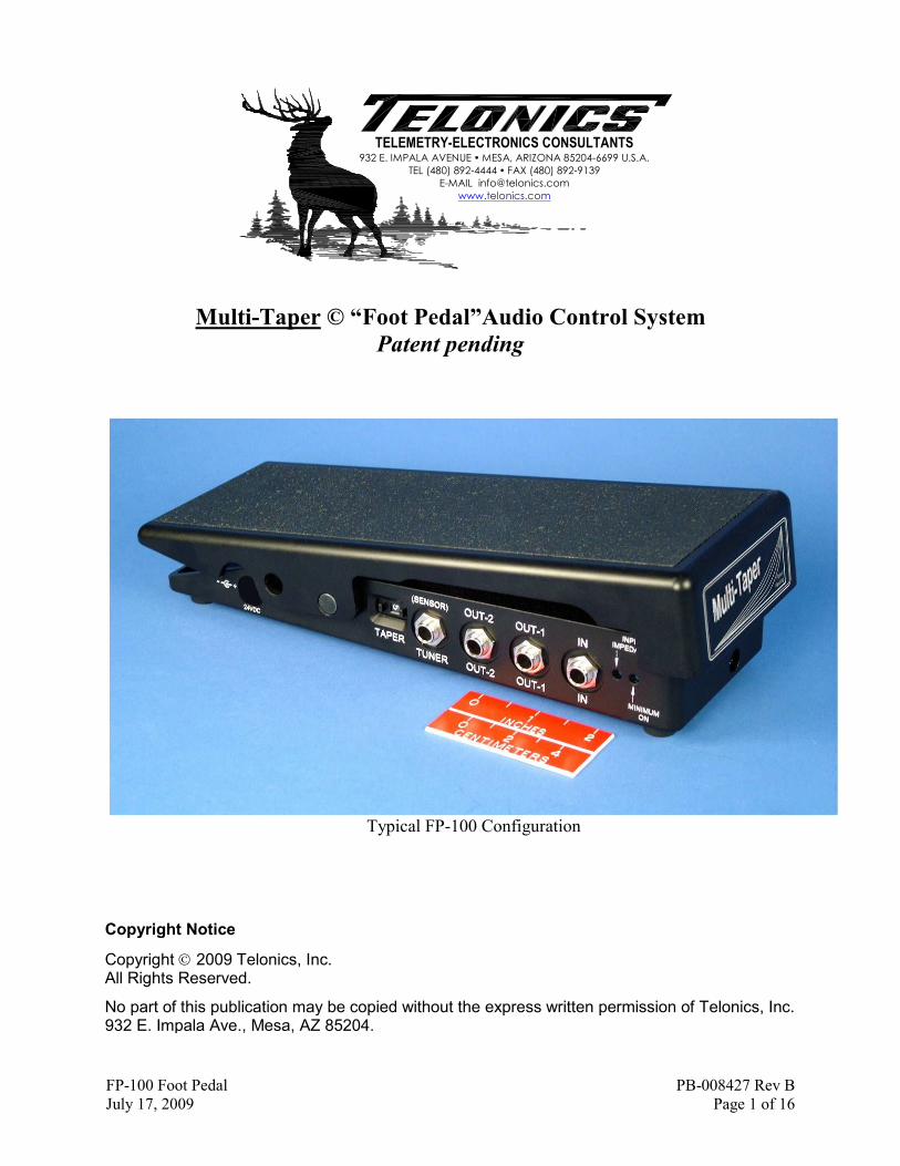
Multi-Taper © “Foot Pedal”Audio Control System
Patent pending
Typical FP-100 Configuration
TELEMETRY-ELECTRONICS CONSULTANTS 932 E. IMPALA AVENUE � MESA, ARIZONA 85204-6699 U.S.A.
TEL (480) 892-4444 � FAX (480) 892-9139
E-MAIL [email protected]
www.telonics.com
Copyright Notice
Copyright 2009 Telonics, Inc. All Rights Reserved.
No part of this publication may be copied without the express written permission of Telonics, Inc., 932 E. Impala Ave., Mesa, AZ 85204.

FP-100 Foot Pedal PB-008427 Rev B
July 17, 2009 Page 2 of 16
Multi-Taper © “Foot Pedal” Audio Control System
General Description:
This “pedal” is the first in a series of advanced technology volume and/or audio effects control
systems based upon a series of revolutionary technologies developed by Telonics, Inc. This
particular system takes the mechanical form of a conventional foot pedal in either the “high” or
“low” profile configuration. It can be used as a foot pedal of the simplest form; however it contains
technical capabilities which far exceed those of any currently available audio dynamics control
device. The basic model includes accurate emulations of virtually all audio tapers of mechanical
potentiometers (“pots”) used in the past, as well as the audio control “taper” of all popular
electronic foot pedals. (Additional replica tapers or custom tapers can be factory added in a very
short time via its USB port). Tapers are selectable by means of a digital switch on the side of the
unit near the input and output jacks. This patent-pending control system does not utilize
potentiometers, encoders or light devices of any type. There are no components to wear out.
It incorporates the latest technology in low-noise, high headroom amplification - in a class with the
latest exceptional dynamic response studio-grade amplifiers, while preserving the warmth of
vintage tone. It is fully buffered, preventing noise from externally connected tuners and other
devices from entering the signal chain as well as providing safety from system malfunction due to
shorted or intermittent cables. A full-time tuner output allows tuning with the pedal in any
position, including the “off”/minimum position. It is factory programmed via a miniature USB
port. Subsequent software updates may be uploaded via this USB port. It is solidly built such that it
will not skate around the floor with foot movement. A blue LED pedal-board light indicates both
proper power and that it is operating within acceptable parameters.
An optional micro-miniature remote sensor is available which assumes full control of the pedal
when plugged in. This remote control system opens limitless possibilities, from mechanical control
by instruments, to usage by musicians who have a physical impairment and have been prevented
from playing until now. (A remote sensor will be supplied at no charge to individuals who suffer
a physical impairment which can be aided by this remote control device).
Its internal circuitry is well-behaved in terms of power supply connection, interruption or
disconnection, thereby minimizing noise which might annoy listeners or possibly damage speaker
systems. This is no garage-shop hobbyist toy. It is the culmination of years of research, designed
and hand-built in the U.S.A. by leading and internationally recognized aerospace engineers,
technicians, assemblers and musicians in a state-of-the-art facility in Mesa, Arizona by Telonics,
Inc., an established leader in scientific instrumentation and communications since the 1970’s.
Dependability, long-term reliability, performance and value are paramount in this pedal.
Telonics, Inc. is well known by scientists world-wide for the manner in which we stand firmly
behind our products on a personal basis. Please contact Dave Beaty with any questions you might
have, we invite design comments and are open to any and all suggestions:
TEL 480 892-4444 ext. 122 FAX 480 892-9139
www.telonics.com

FP-100 Foot Pedal PB-008427 Rev B
July 17, 2009 Page 3 of 16
Mechanical
Pedal: Material: CNC milled 6061-T6 Aluminum with hardened bearing surfaces
Axles are oil-hardened (O1) tool steel, 55-60 C-scale Rockwell
Finish: Heavy hard anodized (Mil-A-8625 Type II, Class 2, 0.002”)
Lettering: Laser-engraved (all markings are burned through the hard
anodize coating. No paints or inks are used on the product,
markings will not smear or wear off.)
Outline
Dimensions: 10.6L x 3.7W x 2.4H in. (27L x 9W x 6.1H cm)
Weight: 2.35 lb (1.06 kg)
Optional External Sensor: Size: 0.8L x 0.9W x 0.125H in. maximum
(20.3L x 22.9W x 3.2H mm) maximum
Connector: ¼” TRS male “Stereo Plug” (Tip-Ring-Shield/Sleeve)
Mechanical Adjustments:
Both DRAG (Ease of Pedal Movement) and TENSION (Pedal
Return Tension) are independently adjustable to suit the
user. Please refer to the photos and drawings provided
in this document:
Drag: A 3/16 (0.187) inch “Allen”-type HEX head cap
screw located on the bottom of the pedal provides a
means of customizing the Drag experienced during
pedal movement. A 3/16 inch HEX wrench is supplied
from the factory for this adjustment. Note that this
adjustment is very sensitive. Turning this screw only a
slight amount will greatly change the ease of pedal
movement. A fraction of a turn Clockwise (CW) will increase drag
(make the pedal more difficult to move). Conversely, a small amount
of adjustment in the Counterclockwise (CCW) direction will
decrease the drag, making the pedal easier to move.

FP-100 Foot Pedal PB-008427 Rev B
July 17, 2009 Page 4 of 16
Tension: A Phillips-head screw on the front face of the base adjusts pedal
return Tension (lift). It can only be
properly adjusted if the Drag
adjustment is fully relieved (set to
minimum drag). It exhibits a very
wide adjustment range, requiring
several turns in either direction to
make an appreciable difference. It
has been factory adjusted with the
drag adjustment set to minimum. If
you should decide to adjust it, first
be sure the Drag screw is turned
CCW to minimum drag, make any
desired tension adjustment, then re-
set the Drag to complete the process.
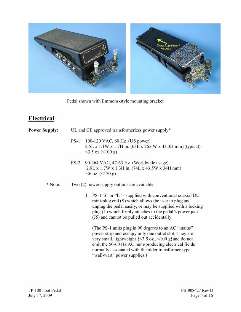
Bracket
Interface: The pedal is designed to interface with most popular pedal bar
brackets which utilize either two screws, or
a triangular three hole pattern. The screws
which attach the two front feet are slightly
longer in order to allow for the thickness of
a bracket.
To mount a two-hole bracket, remove the
two front feet and mount it using the two
screws with the rubber feet still attached
(under the bracket).
To attach three-hole brackets, remove both front feet AND the single
screw just behind them (slightly toward
the center of the pedal). Attach the bracket
using all three screws.
Note that some brackets are not produced
with consistent hole pattern location and
spacing. In some cases it may be
necessary to enlarge a hole or holes, or
even re-drill the odd hole in a bracket.
(Refer to the pictures showing various
types of pedal bar mounting
brackets, no modifications to these
brackets were necessary.)
FP-100 Foot Pedal PB-008427 Rev B
July 17, 2009 Page 5 of 16
Pedal shown with Emmons-style mounting bracket
Electrical:
Power Supply: UL and CE approved transformerless power supply*
PS-1: 100-120 VAC, 60 Hz (US power)
2.5L x 1.1W x 1.7H in. (63L x 26.6W x 43.3H mm) (typical)
<3.5 oz (<100 g)
PS-2: 90-264 VAC, 47-63 Hz (Worldwide usage)
2.9L x 1.7W x 1.3H in. (74L x 43.5W x 34H mm)
<6 oz (<170 g)
* Note: Two (2) power supply options are available:
1. PS-1”S” or “L” - supplied with conventional coaxial DC
mini-plug end (S) which allows the user to plug and
unplug the pedal easily, or may be supplied with a locking
plug (L) which firmly attaches to the pedal’s power jack
(J5) and cannot be pulled out accidentally.
(The PS-1 units plug in 90 degrees to an AC “mains”
power strip and occupy only one outlet slot. They are
very small, lightweight {<3.5 oz., <100 g}and do not
emit the 50-60 Hz AC hum-producing electrical fields
normally associated with the older transformer-type
“wall-wart” power supplies.)
FP-100 Foot Pedal PB-008427 Rev B
July 17, 2009 Page 6 of 16
2. PS-2 International model, slightly larger, with
interchangeable prongs which snap into place for
international use. Supplied with conventional coaxial DC
mini-plug end which allows the user to plug and unplug
the pedal easily.
(Like the PS-1 units described above, the PS-2
International units do not exhibit the 50-60 Hz AC hum-
producing electrical fields normally associated with the
older transformer-type “wall-wart” power supplies.)
Still relatively lightweight, the PS-2 power supplies are
slightly larger than the PS-1 power supplies.
Jacks and Controls: NOTE: All inputs and outputs are buffered and isolated such that shorted or
Intermittent Cables will not damage the pedal, interfere with other
cable functions or adversely effect signal levels.
Inputs: Monaural models are supplied with a *dual-function input jack (J1,
refer to Outline Drawing on page 14) and associated circuitry which
will accept a conventional ¼” TS plug for conventional unbalanced
pickups.
*It will ALSO accept standard TRS plugs for BALANCED line
inputs (for future very low-noise balance-wound pickups.
In Stereo models, input jack J1 accepts a conventional ¼” TRS
stereo plug.
Monaural (MONO) Models:
IN-Unbalanced: Input jack (J1) accepts standard ¼” TS-type audio plug for all conventional unbalanced, high impedance pickups.
The input jack (J1) ALSO accepts BALANCED inputs as follows:
IN-Balanced: In anticipation of forthcoming advances in pickup design, Input jack (J1) also accepts standard ¼” TRS-type plugs for
both high and low impedance balanced pickups. Its associated
circuitry automatically detects the type of input (balanced or
unbalanced) and requires no switching or other user intervention.
FP-100 Foot Pedal PB-008427 Rev B
July 17, 2009 Page 7 of 16
Stereo Models:
IN-Stereo, unbalanced: Input jack (J1) accepts standard ¼” TRS-type INPUT jack for two independent input signal sources
using unbalanced, high impedance pickups. Wiring connections are:
Tip = Left Channel
Ring = Right Channel
Shield = Common signal ground
24VDC (power): J5 is the DC power input jack. It may ONLY be used with a factory supplied power supply. It will accept either
the standard smooth-barrel DC power plug, or the optional ¼-turn
locking type DC power plug. The non-locking plug makes it easy to
remove the power supply for transport, while the locking tabs
prevent the plug from being accidentally being pulled loose.
The unit is specifically designed such that unpleasant loud pops
which might damage speaker systems are NOT generated when (or
if) the power plug is suddenly pulled out while the amplifier systems
are on/live.
OUTPUTS OUT-1: in monaural models, J2 (refer to Outline Drawing on page14) is a conventional ¼ inch TS jack with its audio output level
buffered, and controlled by pedal movement. Audio taper selection is
controlled by the taper program preset switch as well as by a user-
selected “minimum OFF” setting which the user may adjust for each
individual taper.
OUT-2: in monaural models, J3 (refer to Outline Drawing on page 14)) is also a conventional ¼ inch TS jack. This jack provides an
output which is identical to that of OUT-1, and is normally used to
provide a second identical, phase-coherent signal source for players
who wish to feed their signal to a second preamp, combo amp or
special effects system.
In stereo models, J2 and J3 provide individual buffered, analog
signal chain outputs for Left and Right Channels respectively.
TUNER/sensor: J4 (refer to Outline Drawing on page 14) is a dual-function ¼” jack, providing a full-time TUNER OUTPUT
signal, regardless of pedal position (¼” TS-type). This allows the
user to continuously monitor tuning with the pedal in any position,
including the full/minimum off position. This output is buffered and
isolated. It will not allow the noise from digital tuners to get back
into the system.
FP-100 Foot Pedal PB-008427 Rev B
July 17, 2009 Page 8 of 16
This jack (J4) is also used for the optional Telonics Miniature
Remote Sensor (TMRS). It accepts the ¼” TRS-type plug on the
TMRS cable and automatically communicates with the sensor when
the user chooses to use the TMRS instead of the foot pedal to control
volume.
When the remote sensor is plugged into J4 it automatically assumes
full control of the pedal, replacing the control function of the foot
platform.
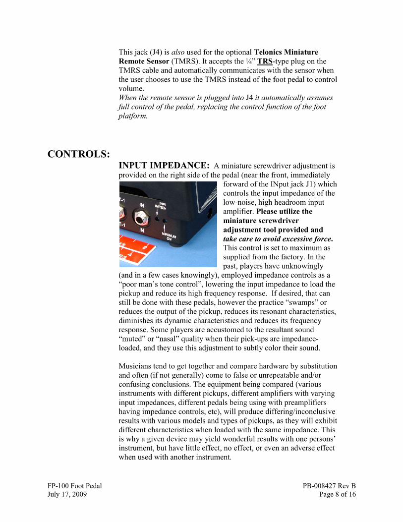
CONTROLS: INPUT IMPEDANCE: A miniature screwdriver adjustment is
provided on the right side of the pedal (near the front, immediately
forward of the INput jack J1) which
controls the input impedance of the
low-noise, high headroom input
amplifier. Please utilize the
miniature screwdriver
adjustment tool provided and
take care to avoid excessive force.
This control is set to maximum as
supplied from the factory. In the
past, players have unknowingly
(and in a few cases knowingly), employed impedance controls as a
“poor man’s tone control”, lowering the input impedance to load the
pickup and reduce its high frequency response. If desired, that can
still be done with these pedals, however the practice “swamps” or
reduces the output of the pickup, reduces its resonant characteristics,
diminishes its dynamic characteristics and reduces its frequency
response. Some players are accustomed to the resultant sound
“muted” or “nasal” quality when their pick-ups are impedance-
loaded, and they use this adjustment to subtly color their sound.
Musicians tend to get together and compare hardware by substitution
and often (if not generally) come to false or unrepeatable and/or
confusing conclusions. The equipment being compared (various
instruments with different pickups, different amplifiers with varying
input impedances, different pedals being using with preamplifiers
having impedance controls, etc), will produce differing/inconclusive
results with various models and types of pickups, as they will exhibit
different characteristics when loaded with the same impedance. This
is why a given device may yield wonderful results with one persons’
instrument, but have little effect, no effect, or even an adverse effect
when used with another instrument.

FP-100 Foot Pedal PB-008427 Rev B
July 17, 2009 Page 9 of 16
Its not rocket science, it’s just that there may be a large number of
complex variables. In such cases, very simple tests can be very
misleading.
If you are using a studio-quality preamplifier with proper tonal
shelving characteristics such as the LeMay-series preamps, it is
suggested that the user leave this control at the factory setting
(maximum clock-wise, very high impedance/little or no pickup
loading) and allow his/her preamplifier to provide control of tonal
characteristics without inhibiting the performance of their pickup..
If conventional amplifiers are used, we suggest that this control be
used very sparingly, and only after all other tonal possibilities on the
amplifier are exhausted. Nonetheless, this control is provided for
those players who have played that way for many years and feel that
they cannot achieve their individual sound any other way.
Note that this control is both small and delicate. Please utilize the
miniature screwdriver adjustment tool provided and take care to
avoid excessive force. The entire range of adjustment occurs over
approximately a 240 degree range. If it were a clock-face,
maximum pickup loading would occur at about 8:00 o’clock (fully
CCW) and minimum loading at 4:00 o’clock (maximum CW). We
suggest that you check and make sure that it is fully clockwise
(CW) when not being used. You can watch the pocket clip on the
adjustment tool provided with the pedal while turning it to get an
idea of where it is set.
MINIMUM ON: An adjustment access hole is provided immediately forward of the Input Impedance access hole on the right
front corner of the pedal. This adjustment controls the minimum
level of audio signal which is
allowed to pass through the pedal
when the control platform is fully
back, or in the MINIMUM sound
level position. Units are factory
adjusted such that the output level
appears OFF to the ear when the
pedal is fully back (the most
popular adjustment setting for the
majority of musicians). The
adjustment range of this control is determined by software. (It is
normally correct for applications encountered thus far, however it
can be factory-altered with very little effort.)

FP-100 Foot Pedal PB-008427 Rev B
July 17, 2009 Page 10 of 16
HOW TO CHANGE the Minimum ON setting for a given taper: If you first understand a bit about how the system operates when you change the minimum
on adjustment, the operation will go much more smoothly.
When the pedal is first powered up, the “brain” inside the pedal “sees” the last setting that
someone made with this control. When you select a given taper with the selector switch, it
checks its memory for the last setting used with that taper, and implements it. Then it
begins to “look at”, or check the minimum on control to see if you are moving it (It checks
for any movement about 60 times each second). If the control is not moved, the brain is
happy and nothing happens.
Now you want to change the setting. The brain has been given a rule, that it is to record your new
setting 10 seconds after you stop moving the control.
The instant you move the adjustment, the brain starts a 10 second countdown – which is
reset to10 each time you move the control. When you finally stop moving the control for a
10 second period, the brain writes (what it now “thinks” is) your “final” setting to a
memory location associated with the taper you are using. It will then recall this setting
each time you select this same taper.
Now that you know the rules for how it works, you may not be so surprised when you
move the control for the first time and the volume suddenly changes initially.
Let’s think about why this might happen; initially the volume is set according to the
position of your pedal, as defined by the taper you have chosen, and modified further by
the last memorized setting of the minimum on control which the brain pulled from memory.
Now you move the control a bit one way or the other. The system immediately adjusts to
the new setting!
If you moved the control up, the sound level jumps to the new increased level. Conversely,
if you happened to move it down, the sound level abruptly drops to the new level.
Of course after that point, you can select any desired level with great precision. Then if
you don’t change the control for 10 seconds, the new setting is written to memory and that
setting will now be the new minimum on setting until you decide to change it.
Note that this control is both small and delicate. Please utilize the adjustment tool
provided and take care to avoid excessive force. The entire range of adjustment
occurs over approximately a 240 degree range. If it were a clock-face, the adjustment
range would occur from about 8:00 o’clock (fully CCW) to about 4:00 o’clock
(maximum CW). You can listen to the audio volume while turning it with the pedal
FULLY BACK, (MINIMUM SOUND position) to determine where it is set.
The pedal will “remember” this setting and store it in FLASH memory along with the
particular taper you have it set to - 10 seconds after you stop moving the control. That
way, when you recall any taper using the TAPER switch (described below), your desired
minimum-off setting will be preserved for that taper.

FP-100 Foot Pedal PB-008427 Rev B
July 17, 2009 Page 11 of 16
TAPER: A means to select the desired audio taper is provided in the form of a taper program preset switch which selects the
desired taper by means of two
small buttons on either side of the
display window. One button
advances the number, the other
reduces the number.
The factory-supplied tapers are as
follows:
1 Hilton* LED light pedal (“new
type” with small detachable
power supply)
2 Goodrich* LED light pedal (green LED model)
3 Goodrich* pot pedal (using Clarostat type EJA1N116P504A)
4 Emmons* factory pot pedal (using classic Allen-Bradley
pot, Type J, JAIN200P504AA)
5 Hilton* LED light pedal (“old type” with large permanently
attached Motorola power supply)
6 thru 9 -other tapers may be added in these positions.
0 is reserved as a programming position and will not respond to
pedal movement.
If a given switch position is unused (currently like 6 thru 9), the
output will be held to a fixed low volume and will not respond to
pedal action.
* Note: Hilton, Emmons and Goodrich are fine companies who produce a good product and
stand behind their products in a commendable manner. Their names are included
solely for comparison of an electronic characteristic exhibited by one or more of
their pedal models; in this case, that characteristic is measured audio taper.
Blue Pedal board Light: The blue light (LED) on the left side of the pedal serves to illuminate the
pedal board, but it also serves as a visible error status reporting interface
between the user and the microprocessors in the pedal. The most important
functions are listed below:

FP-100 Foot Pedal PB-008427 Rev B
July 17, 2009 Page 12 of 16
Pedal attitude invalid : The pedal is designed to be used on a fairly flat
floor surface (unless inclined upward and/or cocked slightly sideways
when attached to pedal boards or when using an Emmons pedal-board
mount). Its attitude control system allows for such usage, but if the pedal
is placed in an attitude which exceeds those normal limits, two things
happen; first the volume is reduced to a fixed, low volume and secondly,
the blue LED will blink rapidly. The unit will revert to normal operation
as soon as it is returned to a valid orientation and attitude.
Error or Fault: If the internal self-test routines encounter an internal
circuitry fault, bad power supply condition or other failure condition, the
LED will blink rapidly.
NOTE: The user may choose to have the blue LED either ON or OFF
(other than when it reports a problem by blinking).
The desired condition may be set using the following procedure:
1. With the power plug removed, set the pedal on a flat surface and
advance or retard the TAPER switch to position “0” (zero).
2. If you wish the LED to be normally ON, tilt the top of the pedal
fully forward (maximum ON) and insert the power plug. The blue
LED will come ON, and it will normally stay ON from that point
forward.
If you wish the LED to be normally OFF, unplug the power cord,
tilt the top of the pedal fully back (minimum ON) and insert the
power plug. The blue LED will not come on, and it will normally
stay OFF from that point forward (unless an error is encountered).
You may then advance or retard the TAPER switch to the taper you prefer
and use the pedal normally.
Signal Path: Some of the most important aspects of your sound are directly influenced
by the signal path from the pickup in your instrument to the initial
preamplifier in your system.
Be very careful what you insert in your signal path. Unless you have a high
grade preamplifier (such as the LeMay preamp series), a high-quality cable
(low capacitance), as short as possible, should be connected from the output of
your instrument to the input jack (J1) of this pedal. The output of the pedal (J2
or/and J3) should likewise be connected to your amplifier using a short length
of high quality, low capacitance cable. You then have a clean, low-noise,
purely analog signal path with great signal handling characteristics.
FP-100 Foot Pedal PB-008427 Rev B
July 17, 2009 Page 13 of 16
If you insert an effects pedal or other device between the pickup of your
instrument and the pedal, you have just prevented yourself from taking
advantage of many of the important capabilities of this pedal.
Such devices will not offer the necessary head-room (instantaneous high
signal level handling characteristics), nor will they offer low-noise
preamplifiers and provide the desired wide-band, airy frequency response.
Additionally, and even worse, many such devices are digital in design.
(While very good digital front ends ‘are’ available, they cost thousands of
dollars and are only found in the highest grade studio recording equipment.)
This means that the lower cost effects units must take the signal from your
pickup and run it through a lower performance A/D, or analog-to-digital
converter. They then process and/or “model” the digital signal to achieve
some desired characteristic (delay, reverb, rotary, chorus, etc). After effect(s)
processing they must convert the processed (and degraded) digital signal
back to analog form in order to feed it to your amplifier using a D/A, or
Digital-to-Analog converter. The A/D and D/A converters do not have the
premium signal handling capabilities of the high-end preamplifier designed
into this pedal. Although set for unity throughout gain, this pedal sets the
stage for everything in your signal chain.
So where “should” you put effect units in your amplifier set-up?
The place for effect hardware devices is in the effects (EFX) loop(s) of your
amplifier, NOT in the direct signal path, and most certainly NOT between
your pickup and the pedal - not even between the pedal and your amplifier.
Additionally, good, high quality effects units are designed to work in
PARALLEL with the analog signal path, this parallel configuration is also
called “FULL WET”. Some of the better effects units (even effects pedals),
are now being designed with a “SERIES/PARALLEL” switch inside the unit
in order to service the old in-line guitar stomp-box/pedal board applications,
while allowing them to work properly in high-end applications such as
recording-grade preamplifiers and studio boards. The reverb unit called “Mr.
Springgy” (which emulates the old spring reverb units) is a typical example.
The better effects rack units (such as the Lexicon MX-200), are designed
with two (2) sets (or “banks”) of effects, both a serial bank and a parallel
bank. Setting such EFX units to parallel mode and using them in conjunction
with a high quality preamplifier offering parallel EFX loops provides the
highest level of audio performance.
FP-100 Foot Pedal PB-008427 Rev B
July 17, 2009 Page 14 of 16
Signal Path Discussion Summary:
In summary, if you have a conventional amplifier, connect your pedal
directly between your instrument and the input of your amplifier. Do not
insert effects units, impedance matching boxes or any type of preamplifier
device between the instrument and the pedal.
If you have a high (studio) quality preamplifier which provides input
circuitry equal to that of this pedal, connect your instrument directly to the
input of the preamplifier, then insert the pedal (using two cables, one IN and
one OUT) in the INSERT/Pre-EQ EFX loop of your preamplifier (this point
inserts the pedal in the signal chain immediately after the first stage of
amplification and prior to the EQ/tone shaping circuitry. The LeMay
preamplifier series provides a pair of IN and OUT jacks specifically for this
purpose as well as providing a separate EFX loop (mono or stereo) for
parallel-mode effects units).

FP-100 Foot Pedal PB-008427 Rev B
July 17, 2009 Page 15 of 16
Outline Drawings
TUNER
OUT-2
INOUT-1
TAPER
MINIMUM
ON
24VDC
(SENSOR)
OUT-2
OUT-1
IN
TUNER
OUT-2
OUT-1
INTAPER
MINIMUM
ON
24VDC
(SENSOR)
OUT-2
OUT-1
INJ1
J2
J3
J4
J5
SW1

FP-100 Foot Pedal PB-008427 Rev B
July 17, 2009 Page 16 of 16
TUNER OUT-2 INOUT-1TAPER MINIMUM
ON24VDC
(SENSOR) OUT-2 OUT-1 IN
TUNER OUT-2 OUT-1 INTAPER MINIMUM
ON24VDC
(SENSOR) OUT-2 OUT-1 IN
J1J2J3J4J5 SW1
INPUTINPUT
J1J2J3J4J5 SW1
PRE-EQ INSERT
OR
PEDAL IN/OUTIN OUT
INPUT
(SENSOR) OUT-2 OUT-1 IN
TUNER OUT-2 OUT-1 INTAPER MINIMUM
ON24VDC
J1J2J3J4J5 SW1
INPUTINPUT
L
R
Quick Connection Diagram