Multi-Story Lateral Design - WoodWorks Shear Accumulation • Shear forces are additive from floor...
102
Lateral Design of Mid- Rise Wood Structures Presented by Ricky McLain, MS, PE, SE Technical Director – WoodWorks Chicago Area Workshops – April, 2017
Transcript of Multi-Story Lateral Design - WoodWorks Shear Accumulation • Shear forces are additive from floor...
LateralDesignofMid-RiseWoodStructures
PresentedbyRickyMcLain,MS,PE,SE
TechnicalDirector– WoodWorks
ChicagoAreaWorkshops – April, 2017

Follow the
load

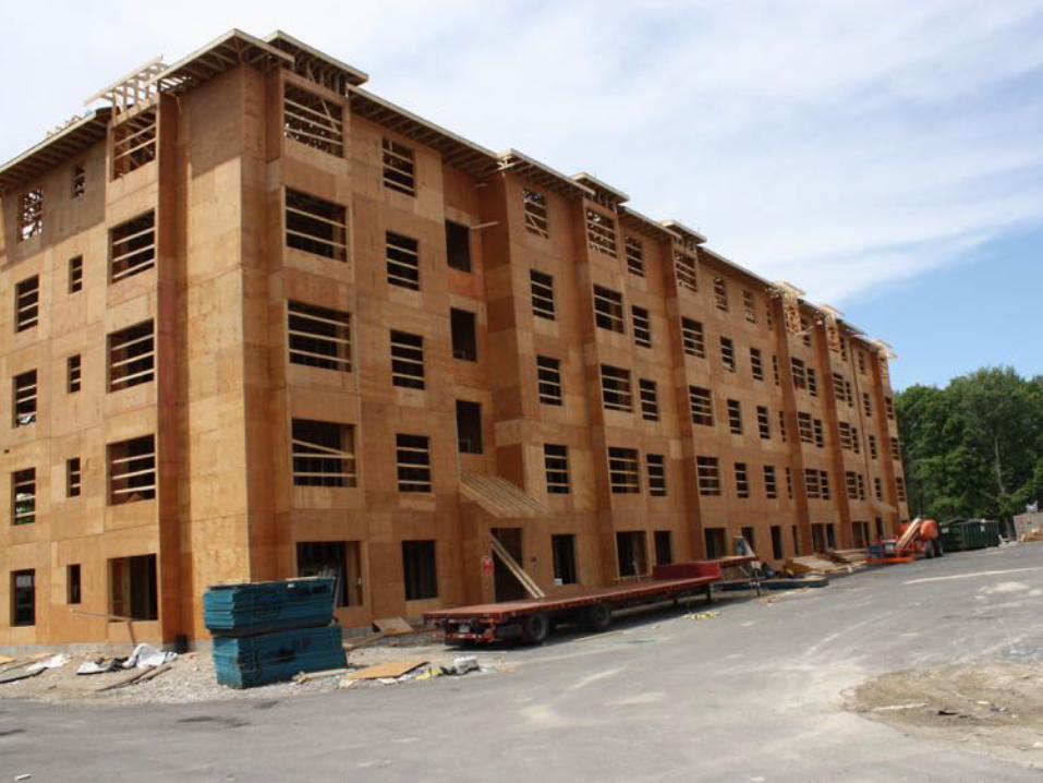
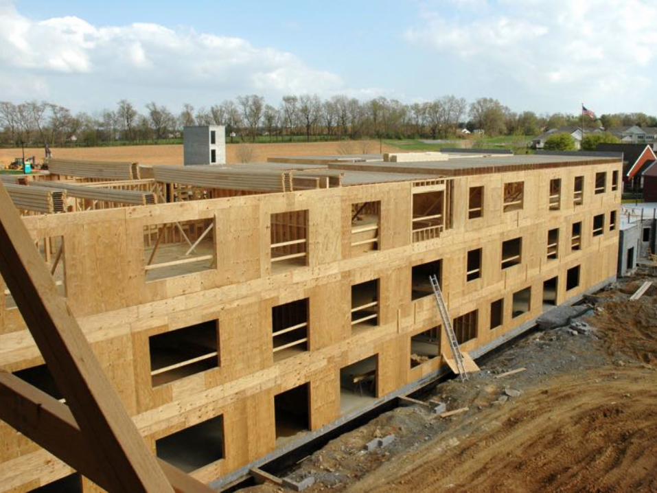
Multi-StoryWoodDesign
Photocredit:MattTodd&PBArchitects
Following the load…

LoadPathContinuity
Photocredit:MattTodd&PBArchitects
Karuna IHolst Architecture
Photo: Terry Malone

Multi-StoryConsiderations
• WindLoadPaths
• Multi-StoryStackedShearWallEffects
• AccumulationofOverturningLoads
• ShearWallDeflection
• DiaphragmModeling
• DiscontinuousShearWalls

WindLoadDistributiontoShearwalls
WindLoadDistributiontoShearwalls

WindLoadDistributiontoShearwalls
Photocredit:MattTodd&PBArchitects
Multi-StoryWindLoadDesign
Photocredit:MattTodd&PBArchitects
DesignPrinciplesaretheSame
Rememberto:FOLLOWTHELOAD!

Multi-StoryWindLoadDesign
WINDSURFACELOADSONWALLS
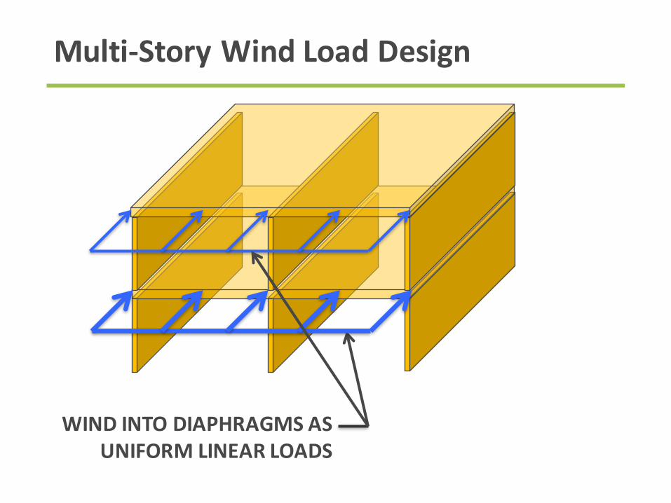
Multi-StoryWindLoadDesign
WINDINTODIAPHRAGMSASUNIFORMLINEARLOADS

Multi-StoryWindLoadDesign
DIAPHRAGMSSPANBETWEEN
SHEARWALLS
WINDINTOSHEARWALLSASCONCENTRATEDLOADS
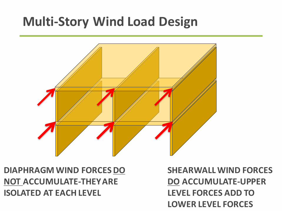
Multi-StoryWindLoadDesign
DIAPHRAGMWINDFORCESDONOTACCUMULATE-THEYAREISOLATEDATEACHLEVEL
SHEARWALLWINDFORCESDO ACCUMULATE-UPPERLEVELFORCESADDTOLOWERLEVELFORCES

DesignExample:FiveOverOneWoodFrame
Freedownloadat
woodworks.org

Multi-StoryWindDesign
ElevationSource:WoodWorks Five-StoryWood-Frame
StructureoverPodiumSlabDesignExample

Multi-StoryWindDesign
FloorPlan
Source:WoodWorks Five-StoryWood-Frame
StructureoverPodiumSlabDesignExample
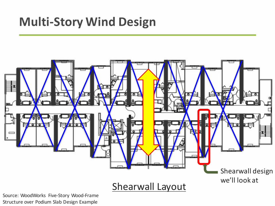
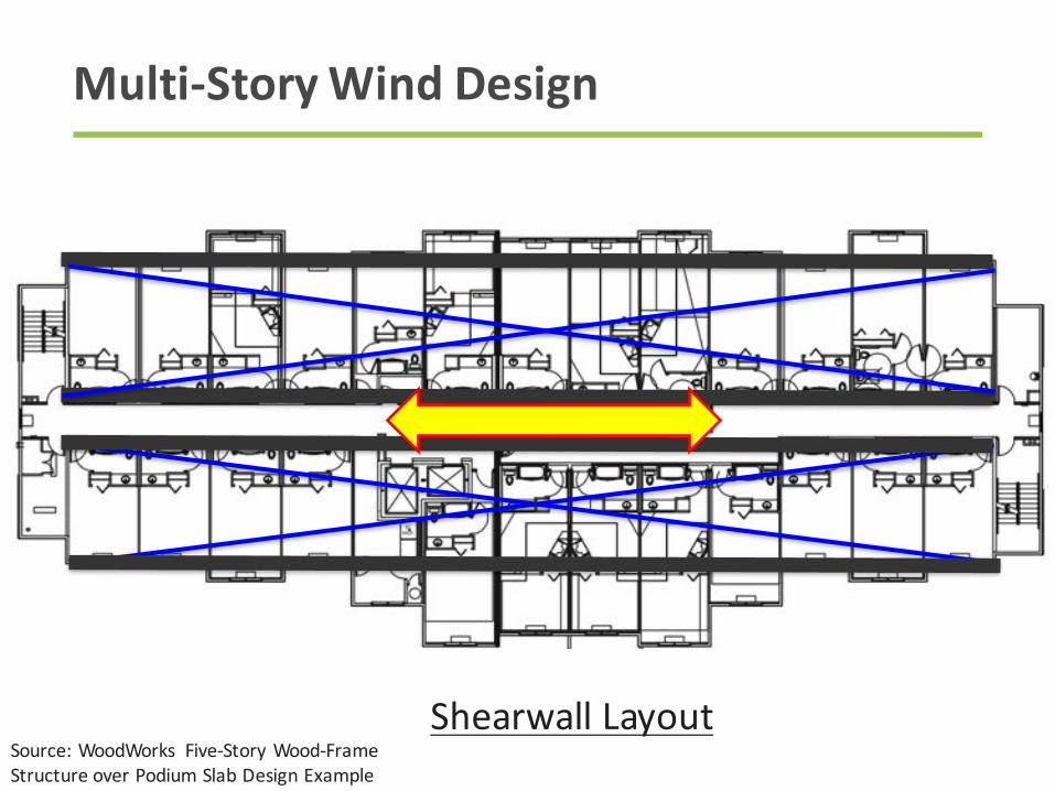
Multi-StoryWindDesign
Shearwall Layout
Source:WoodWorks Five-StoryWood-Frame
StructureoverPodiumSlabDesignExample
Shearwall design
we’lllookat
Multi-StoryWindDesign
Shearwall Layout
Source:WoodWorks Five-StoryWood-Frame
StructureoverPodiumSlabDesignExample
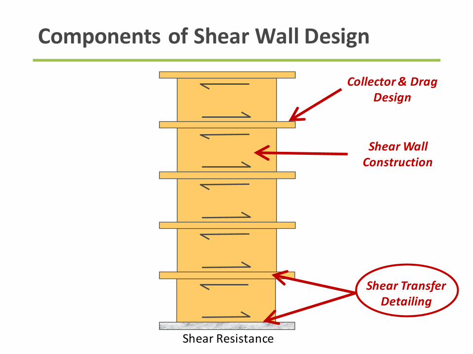
ComponentsofShearWallDesign
Collector&DragDesign
ShearWallConstruction
ShearTransferDetailing
ShearResistance

ComponentsofShearWallDesign
Typ.ShearWallElevation
WindForcesPerStory29’-0”
10’-0”Typ.
F5
=5.2k
F4
=3.8k
F3
=3.7k
F2
=3.6k
F1
=3.4k
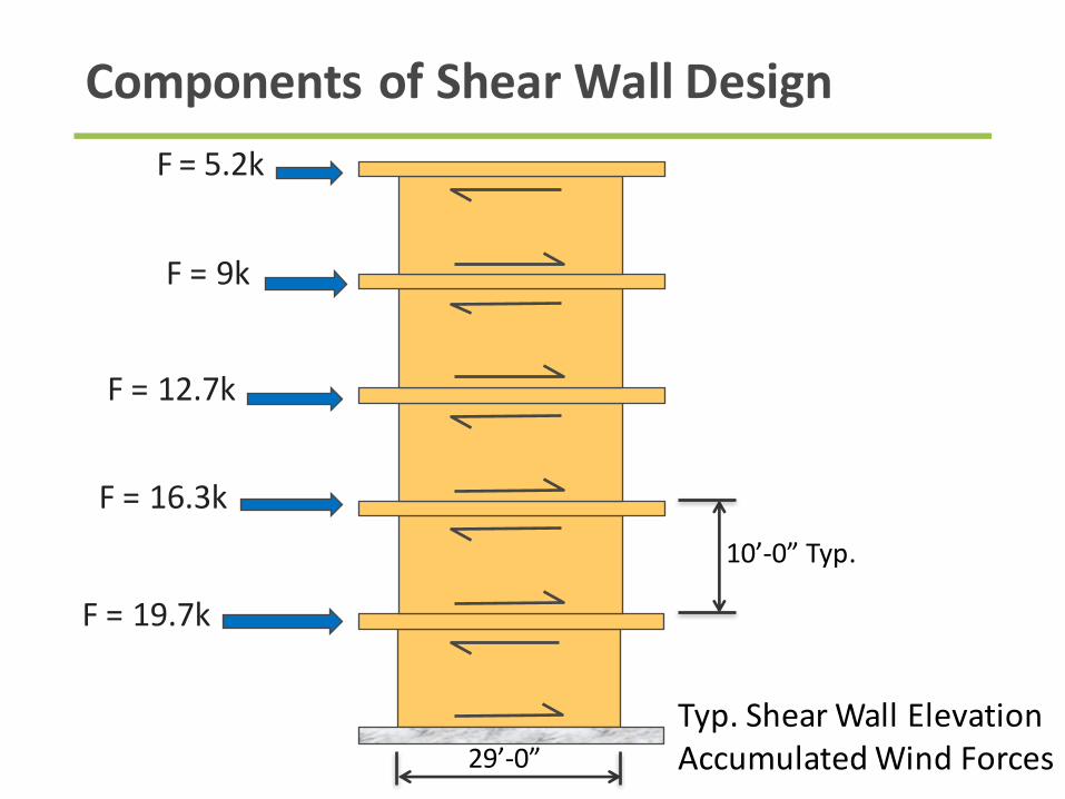
ComponentsofShearWallDesign
Typ.ShearWallElevation
AccumulatedWindForces29’-0”
10’-0”Typ.
F =5.2k
F=9k
F=12.7k
F=16.3k
F=19.7k
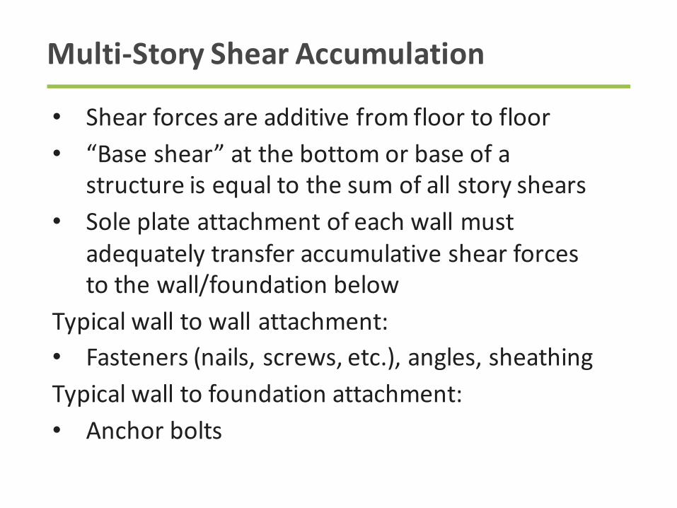
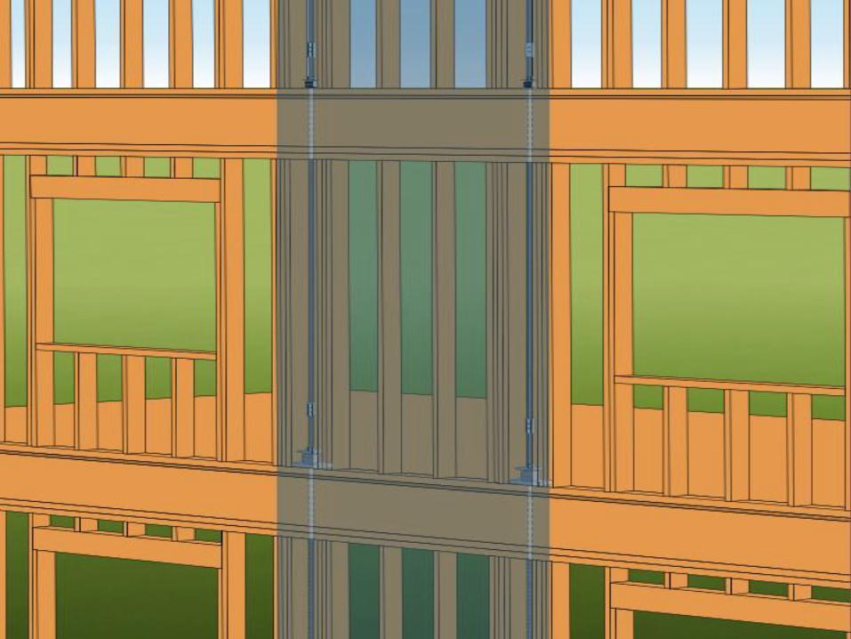
Multi-StoryShearAccumulation
• Shearforcesareadditivefromfloortofloor
• “Baseshear”atthebottomorbaseofa
structureisequaltothesumofallstoryshears
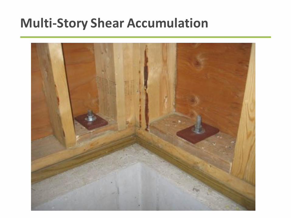
• Soleplateattachmentofeachwallmust
adequatelytransferaccumulativeshearforces
tothewall/foundationbelow
Typicalwalltowallattachment:
• Fasteners(nails,screws,etc.),angles,sheathing
Typicalwalltofoundationattachment:
• Anchorbolts
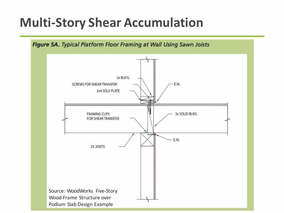
Multi-StoryShearAccumulation
Source:WoodWorks Five-Story
Wood-Frame Structureover
PodiumSlabDesignExample
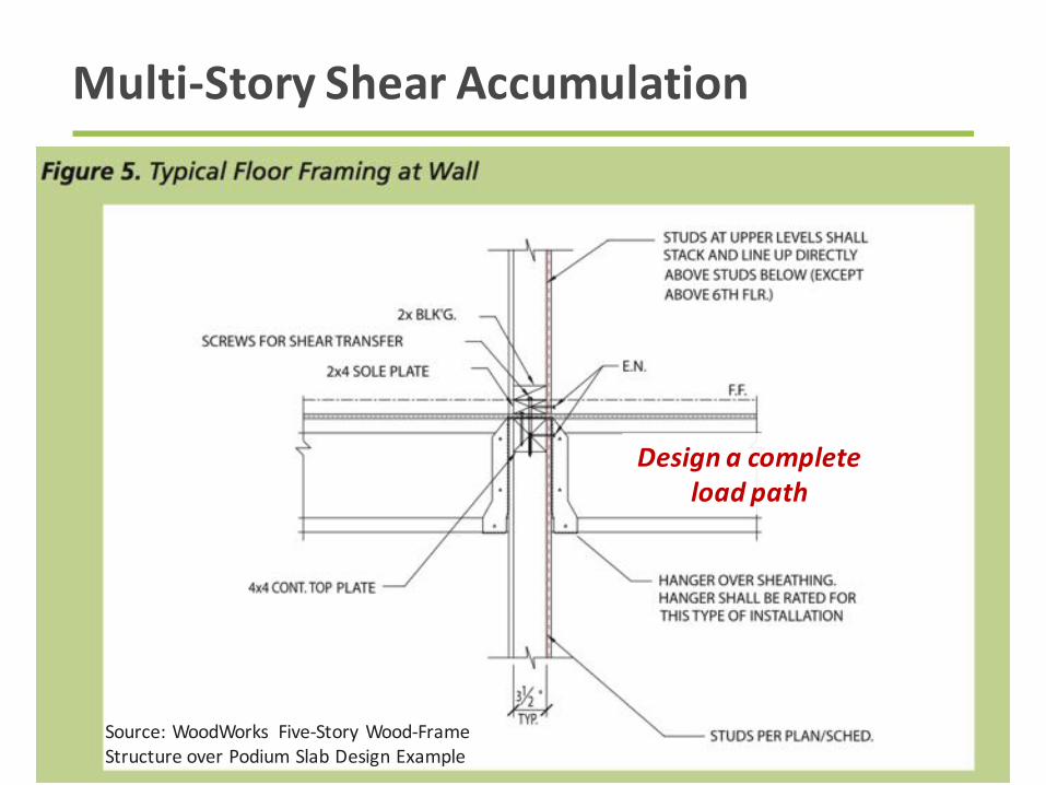
Multi-StoryShearAccumulation
Source:WoodWorks Five-StoryWood-Frame
StructureoverPodiumSlabDesignExample
Designacompleteloadpath
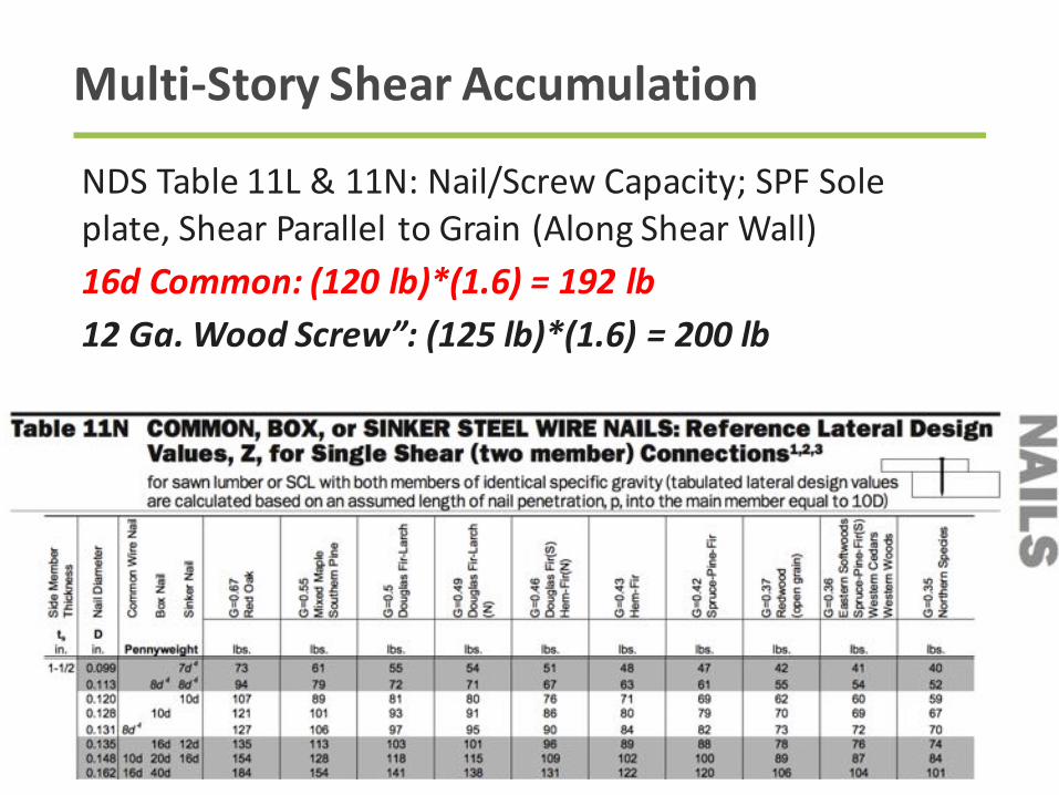
Multi-StoryShearAccumulation
NDSTable11L&11N:Nail/ScrewCapacity;SPFSole
plate,ShearParalleltoGrain(AlongShearWall)
16dCommon:(120lb)*(1.6)=192lb12Ga.WoodScrew”:(125lb)*(1.6)=200lb
Multi-StoryShearAccumulation
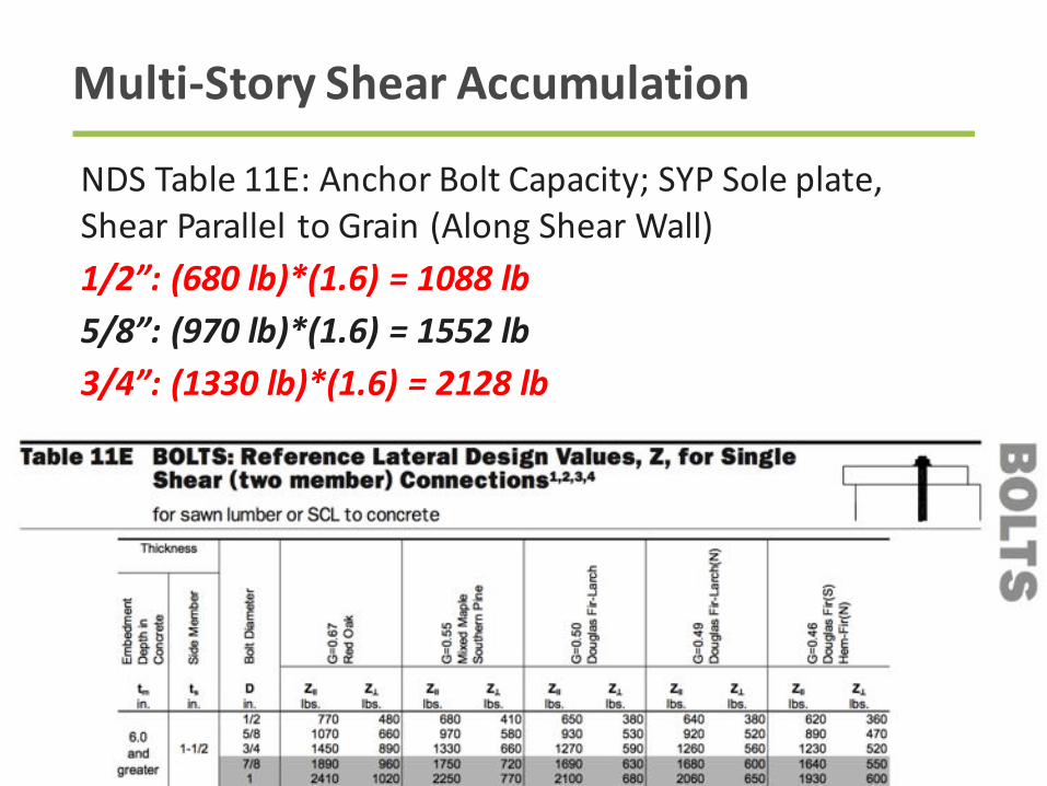
Multi-StoryShearAccumulation
NDSTable11E:AnchorBoltCapacity;SYPSoleplate,
ShearParalleltoGrain(AlongShearWall)
1/2”:(680lb)*(1.6)=1088lb5/8”:(970lb)*(1.6)=1552lb3/4”:(1330lb)*(1.6)=2128lb

Shearwall Nailing
Level AccumShear
ASDShear
ASDUnitShear
WallSheathed
FastenerEdge
Spacing
Allow.Shear
5
th
Floor
5.2k 3.1k 107plf 1side 6” 336plf
4
th
Floor
9 k 5.4k 186plf 1side 6” 336plf
3
rd
Floor
12.7 k 7.6k 262plf 1side 6” 336plf
2
nd
Floor
16.3 k 9.8k 338plf 1side 4” 490plf
1
st
Floor
19.7 k 11.8k 407plf 1side 4” 490plf
Assumes15/32”RatedSheathing, 8dnails,SPFFraming

Shearwall ShearAnchorage
Level AccumShear
ASDShear
ASDUnitShear
Fastener FastenerSpacing
Allow.Shear
5
th
Floor
5.2k 3.1k 107plf 16d 2@16” 288plf
4
th
Floor
9 k 5.4k 186plf 16d 2@16” 288plf
3
rd
Floor
12.7 k 7.6k 262plf 16d 2@16” 288plf
2
nd
Floor
16.3 k 9.8k 338plf 16d 3@16” 432plf
1
st
Floor
19.7 k 11.8k 407plf ½“A.B. 2’-8” 408plf
MakingourBuildingsSafe- Wind

ComponentsofShearWallDesign
Holdown
Anchorage
BoundaryPosts
CompressionTension
OverturningResistance

OverturningForceCalculation
F =5.2k
F=9k
F=12.7k
F=16.3k
F=19.7k
T=C=F*h/L
T&Carecumulativeatlowerstories
Lismomentarm,notentirewalllength
1.9k
5.1k
9.6k
15.4k
22.5k
h
LAssumeL=29ft-1ft=28ft
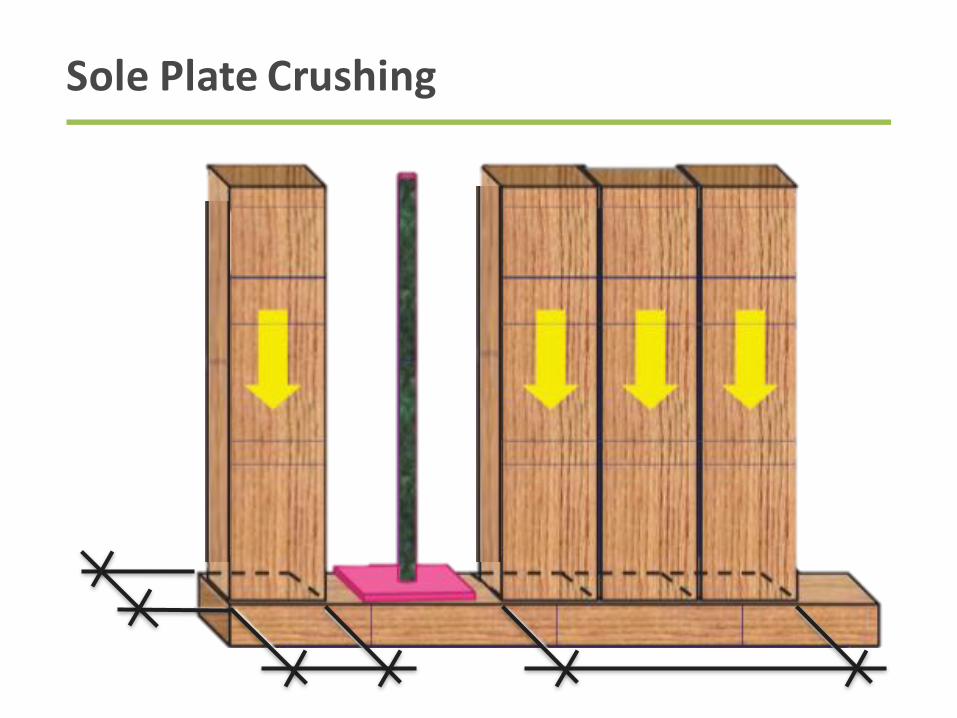
SolePlateCrushing

SolePlateCrushing
Compressionforcesperpendiculartograincancauselocalized
woodcrushing.NDSvaluesforwithmetalplatebearing
onwood resultinamaximumwoodcrushingof0.04”.
Relationshipisnon-linear

SolePlateCrushing
NDSCommentaryC4.2.6:whenajointismadeoftwo
woodmembersandbothareloadedperpendicularto
grain,theamountofdeformationwillbeapproximately2.5
timesthatofametalplatetowoodjoint.
Source:WoodWorks Five-StoryWood-Frame
StructureoverPodiumSlabDesignExample

CompressionPostSize&SolePlateCrush
Level Compression RequiredBearingArea
PostSize
Story SolePlateCrush
5xSolePlateCrush
5
th
Floor 1.9k 4.4in
2
(2)-2x4 0.011” 0.057”
4
th
Floor 5.1k 11.9in
2
(2)-4x4 0.013” 0.067”
3
rd
Floor 9.6 k 22.6 in
2
(2)-4x4 0.034” 0.171”
2
nd
Floor 15.4k 36.3in
2
(3)-4x4 0.039” 0.195”
1
st
Floor 22.5k 39.8in
2
(4)-4x4 0.026” 0.13”
Floors2-5useS-P-F#2SolePlate,Fcperp
=425psi
Floor1useSYP#2SolePlate,Fcperp
=565psi

StorytoStoryCompressionForceTransfer
Source:WoodWorksFive-StoryWood-Frame
StructureoverPodiumSlabDesignExample
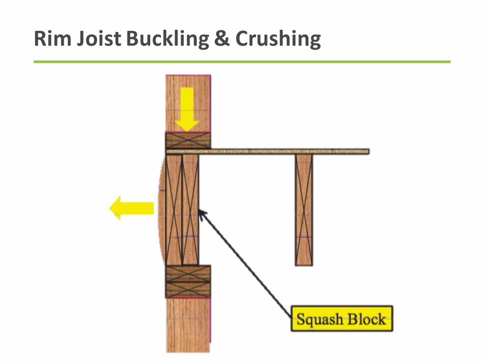
RimJoistBuckling&Crushing
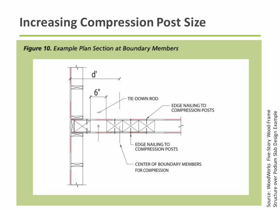
IncreasingCompressionPostSize
Source:WoodWorksFive-StoryWood-Frame
StructureoverPodiumSlabDesignExample
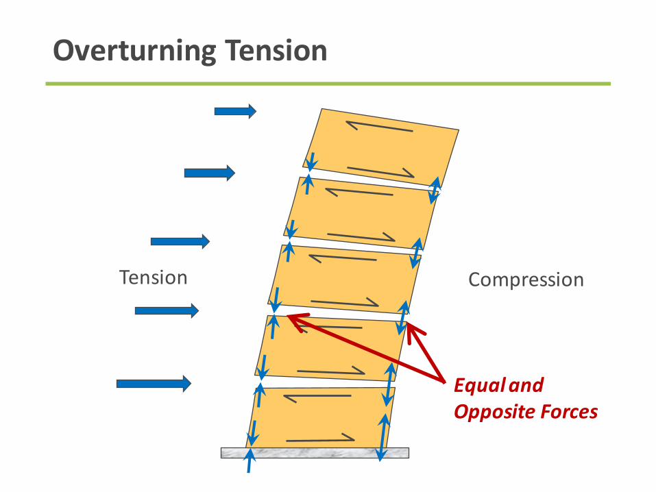
OverturningTension
EqualandOppositeForces
CompressionTension
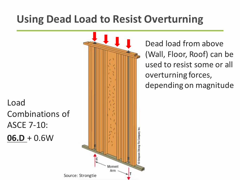
UsingDeadLoadtoResistOverturning
Source:Strongtie
Deadloadfromabove
(Wall,Floor,Roof)canbe
usedtoresistsomeorall
overturningforces,
dependingonmagnitude
Load
Combinationsof
ASCE7-10:
06.D+0.6W

ShearWallHoldown Options
StandardHoldownInstallationStrapHoldown
Installation
…………
………
Continuous RodTiedown Systems
6+kipstorytostorycapacities
13+kipcapacities
100+kipcapacities20+kips/level

ComponentsofShearWallDesign
Tensionaccumulatesinrod.Bearingplatesseelocaloverturningonly.Tensionzone
boundaryframingincompression!
Continuous RodHoldown System
Overturningrestraintat
bearingplateattopofstory
1.9k
3.2k
4.5k
5.8k
7.1k
1.9k
5.1k
9.6k
15.4k
22.5k
F =5.2k
F=9k
F=12.7k
F=16.3k
F=19.7k
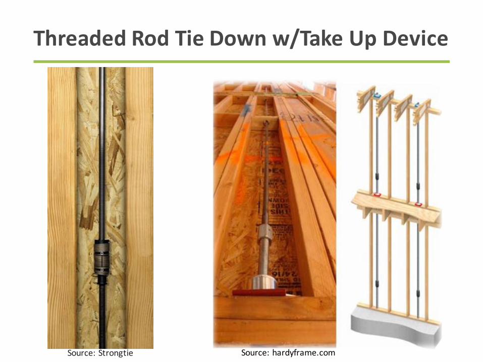
ThreadedRodTieDownw/TakeUpDevice
Source:Strongtie Source:hardyframe.com

ThreadedRodTieDownw/oTakeUpDevice

Uplift ResistanceShear Wall Overturning Resistance
KeyDifferences:
• Rodlocation
• Loaddirection
• Framing
Requirements
• Loadpath
• Shrinkage/
compression
location
GraphicsSource:Strongtie
OverturningResistancevs.UpliftResistance

TieDowns:SkippedFloorsvs.AllFloors
Source:Strongtie
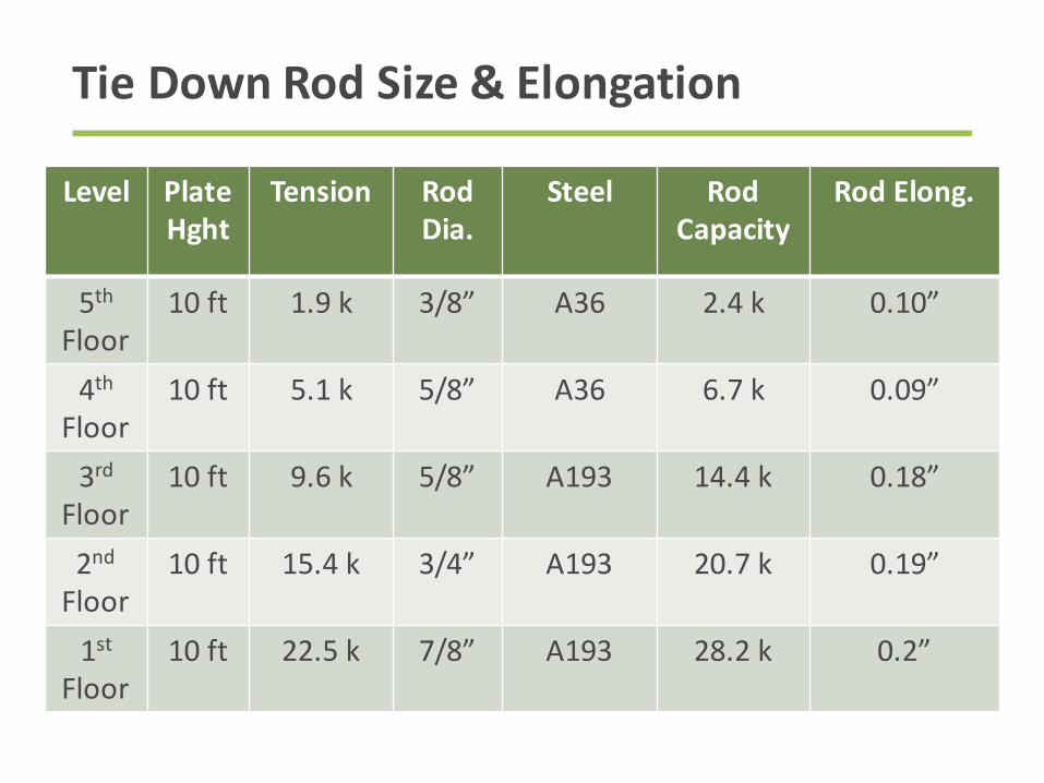
TieDownRodSize&Elongation
Level PlateHght
Tension RodDia.
Steel RodCapacity
RodElong.
5
th
Floor
10ft 1.9k 3/8” A36 2.4k 0.10”
4
th
Floor
10ft 5.1k 5/8” A36 6.7k 0.09”
3
rd
Floor
10ft 9.6 k 5/8” A193 14.4 k 0.18”
2
nd
Floor
10ft 15.4k 3/4” A193 20.7 k 0.19”
1
st
Floor
10ft 22.5k 7/8” A193 28.2 k 0.2”
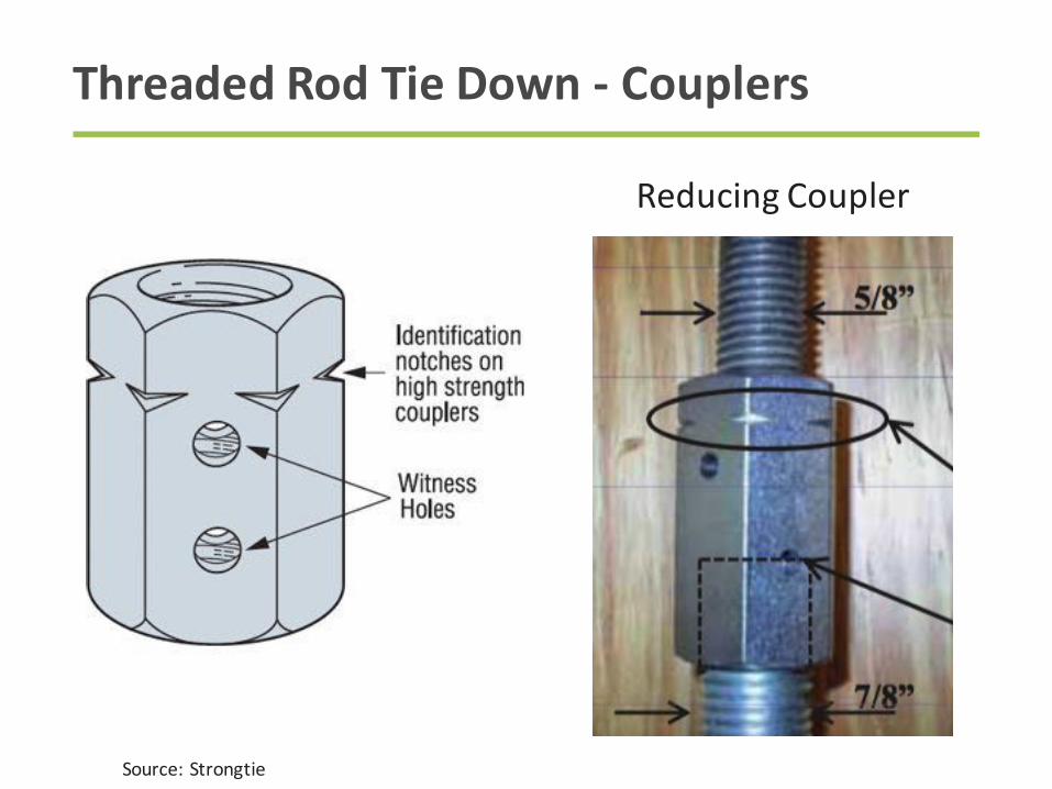
ThreadedRodTieDown- Couplers
ReducingCoupler
Source:Strongtie
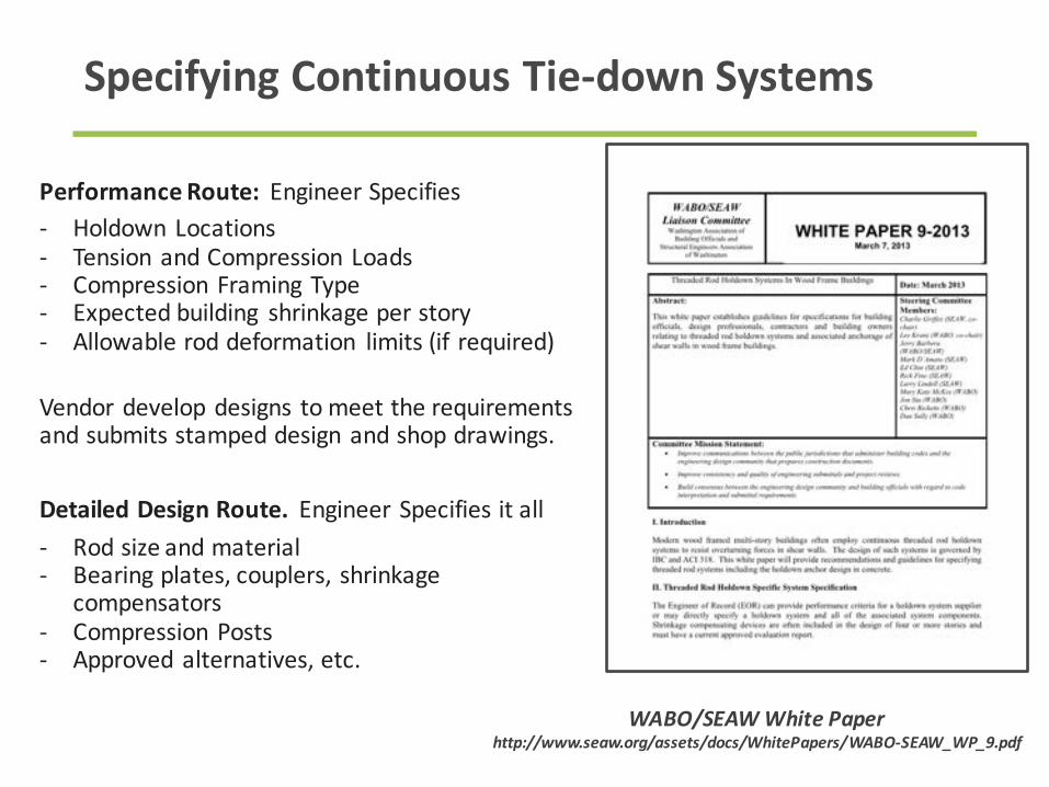
PerformanceRoute:EngineerSpecifies- Holdown Locations
- TensionandCompressionLoads
- CompressionFramingType
- Expectedbuilding shrinkageperstory
- Allowableroddeformation limits(if required)
Vendordevelopdesigns tomeettherequirements
andsubmitsstampeddesignandshopdrawings.
DetailedDesignRoute.EngineerSpecifiesitall
- Rodsizeandmaterial
- Bearingplates,couplers, shrinkage
compensators
- CompressionPosts
- Approvedalternatives,etc.
SpecifyingContinuousTie-downSystems
WABO/SEAWWhitePaperhttp://www.seaw.org/assets/docs/WhitePapers/WABO-SEAW_WP_9.pdf
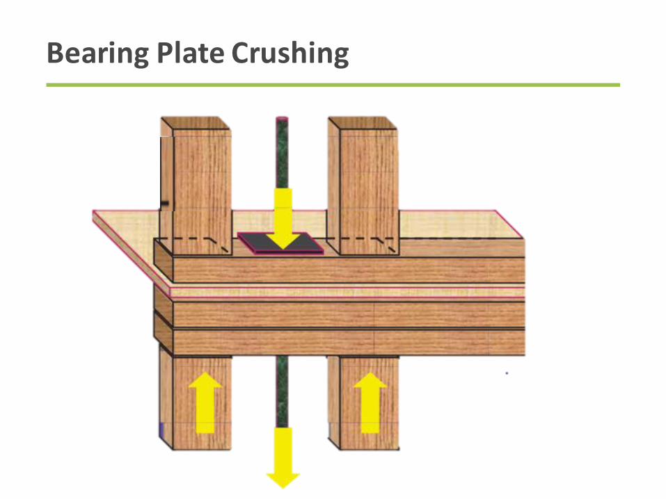
BearingPlateCrushing
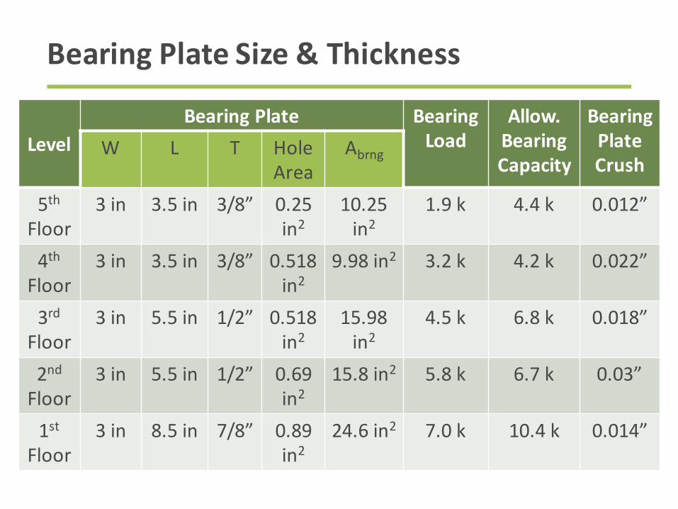
BearingPlateSize&Thickness
LevelBearingPlate Bearing
LoadAllow.BearingCapacity
BearingPlateCrush
W L T Hole
Area
A
brng
5
th
Floor
3 in 3.5in 3/8” 0.25
in
2
10.25
in
2
1.9k 4.4k 0.012”
4
th
Floor
3in 3.5in 3/8” 0.518
in
2
9.98in
2
3.2k 4.2 k 0.022”
3
rd
Floor
3in 5.5in 1/2” 0.518
in
2
15.98
in
2
4.5k 6.8 k 0.018”
2
nd
Floor
3in 5.5in 1/2” 0.69
in
2
15.8in
2
5.8k 6.7 k 0.03”
1
st
Floor
3 in 8.5in 7/8” 0.89
in
2
24.6in
2
7.0k 10.4k 0.014”

Shearwall Deformation– SystemStretch
Totalsystemstretch
includes:
• RodElongation
• Take-updevice
displacement
• BearingPlateCrushing
• SolePlateCrushing
Source:WoodWorks Five-StoryWood-Frame
StructureoverPodiumSlabDesignExample
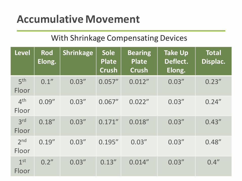
AccumulativeMovement
Level RodElong.
Shrinkage SolePlateCrush
BearingPlateCrush
TakeUpDeflect.Elong.
TotalDisplac.
5
th
Floor
0.1” 0.03” 0.057” 0.012” 0.03” 0.23”
4
th
Floor
0.09” 0.03” 0.067” 0.022” 0.03” 0.24”
3
rd
Floor
0.18” 0.03” 0.171” 0.018” 0.03” 0.43”
2
nd
Floor
0.19” 0.03” 0.195” 0.03” 0.03” 0.48”
1
st
Floor
0.2” 0.03” 0.13” 0.014” 0.03” 0.4”
WithShrinkageCompensatingDevices

Shearwall TieDownElongation
SDPWSDefinitionofΔa
:“Totalverticalelongationofwallanchoragesystem(includingfastenerslip,deviceelongation,rodelongation,etc.)attheinducedunitshearinthewall.
Source:WoodWorks Five-StoryWood-Frame
StructureoverPodiumSlabDesignExample
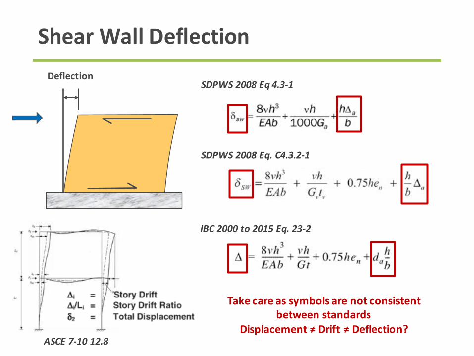
ShearWallDeflection
SDPWS2008Eq 4.3-1
SDPWS2008Eq.C4.3.2-1
Deflection
Takecareassymbolsarenotconsistentbetweenstandards
Displacement≠Drift≠Deflection?ASCE7-1012.8
IBC2000to2015Eq.23-2
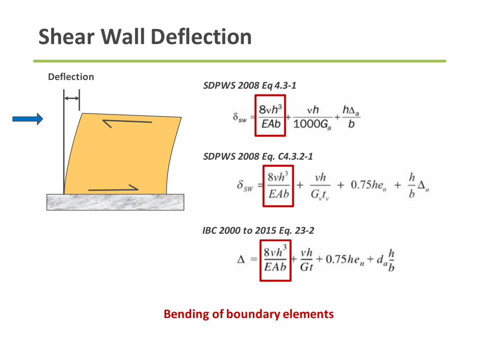
ShearWallDeflection
SDPWS2008Eq 4.3-1
SDPWS2008Eq.C4.3.2-1
Deflection
Bendingofboundaryelements
IBC2000to2015Eq.23-2

ShearWallDeflection
SDPWS2008Eq 4.3-1
SDPWS2008Eq.C4.3.2-1
Deflection
ShearDeformationofSheathingPanels&
Slipofnails@paneltopanelconnections
IBC2000to2015Eq.23-2

ShearWallDeflection
SDPWS2008Eq 4.3-1
SDPWS2008Eq.C4.3.2-1
IBC2000to2015Eq.23-2
Deflection
RigidBodyRotation
b
h
Δa
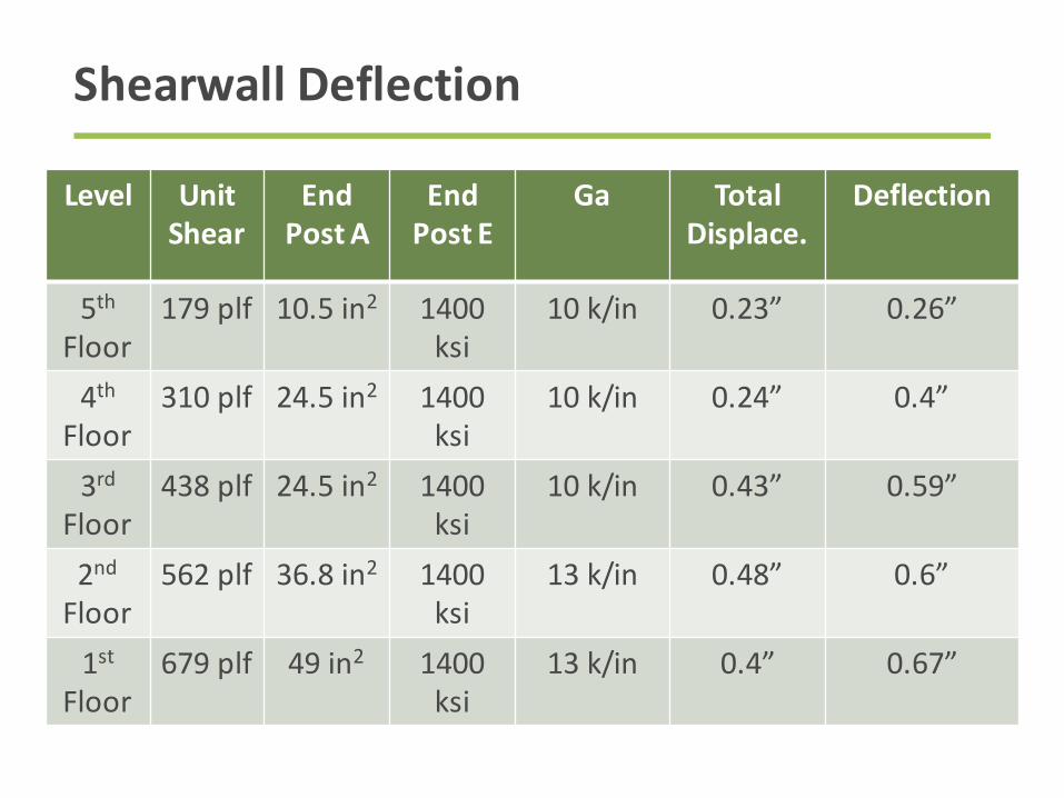
Shearwall Deflection
Level UnitShear
EndPostA
EndPostE
Ga TotalDisplace.
Deflection
5
th
Floor
179plf 10.5in
2
1400
ksi
10k/in 0.23” 0.26”
4
th
Floor
310plf 24.5in
2
1400
ksi
10k/in 0.24” 0.4”
3
rd
Floor
438plf 24.5in
2
1400
ksi
10k/in 0.43” 0.59”
2
nd
Floor
562plf 36.8in
2
1400
ksi
13k/in 0.48” 0.6”
1
st
Floor
679plf 49in
2
1400
ksi
13k/in 0.4” 0.67”
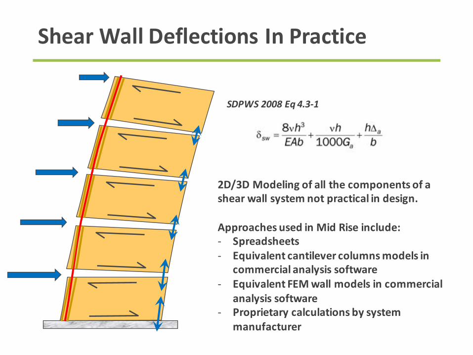
ShearWallDeflectionsInPractice
2D/3DModelingofallthecomponentsofashearwallsystemnotpracticalindesign.
ApproachesusedinMidRiseinclude:- Spreadsheets- Equivalentcantilevercolumnsmodelsin
commercialanalysissoftware- EquivalentFEMwallmodelsincommercial
analysissoftware- Proprietarycalculationsbysystem
manufacturer
SDPWS2008Eq 4.3-1
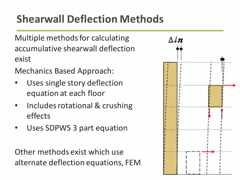
Shearwall DeflectionMethods
Multiplemethodsforcalculating
accumulativeshearwall deflection
exist
MechanicsBasedApproach:
• Usessinglestorydeflection
equationateachfloor
• Includesrotational&crushing
effects
• UsesSDPWS3partequation
Othermethodsexistwhichuse
alternatedeflectionequations,FEM
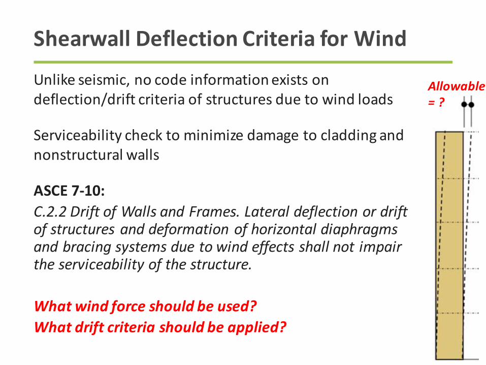
Shearwall DeflectionCriteriaforWind
Unlikeseismic,nocodeinformationexistson
deflection/driftcriteriaofstructuresduetowindloads
Serviceabilitychecktominimizedamagetocladdingand
nonstructuralwalls
ASCE7-10:C.2.2DriftofWallsandFrames.Lateraldeflectionordriftofstructuresanddeformationofhorizontaldiaphragmsandbracingsystemsduetowindeffectsshallnotimpairtheserviceabilityofthestructure.
Whatwindforceshouldbeused?Whatdriftcriteriashouldbeapplied?
Allowable=?
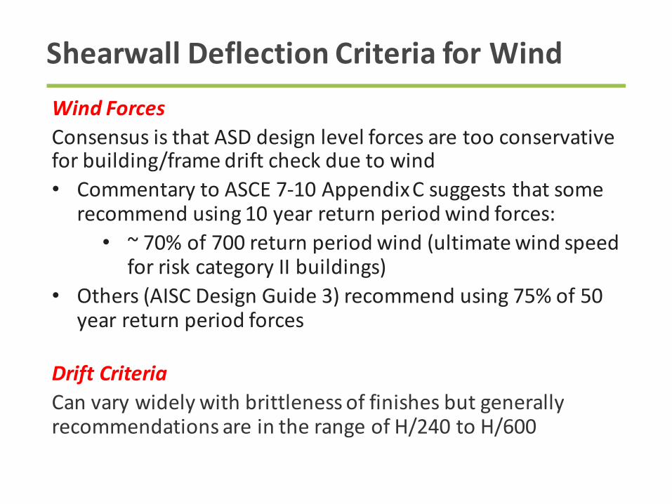
Shearwall DeflectionCriteriaforWind
WindForcesConsensusisthatASDdesignlevelforcesaretooconservative
forbuilding/framedriftcheckduetowind
• CommentarytoASCE7-10AppendixCsuggeststhatsome
recommendusing10yearreturnperiodwindforces:
• ~70%of700returnperiodwind(ultimatewindspeed
forriskcategoryIIbuildings)
• Others(AISCDesignGuide3)recommendusing75%of50
yearreturnperiodforces
DriftCriteriaCanvarywidelywithbrittlenessoffinishesbutgenerally
recommendationsareintherangeofH/240toH/600
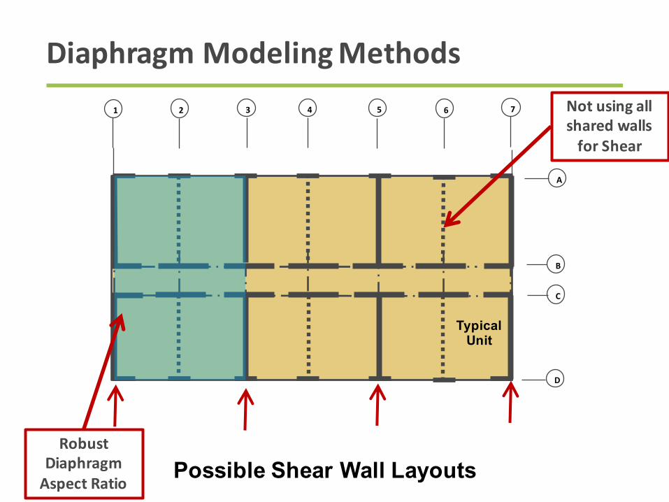
DiaphragmModelingMethods
Possible Shear Wall Layouts
Typical Unit
7654321
D
C
B
A
NotusingallsharedwallsforShear
RobustDiaphragmAspectRatio

DiaphragmModelingMethods
Possible Shear Wall Layouts
Typical Unit
7654321
D
C
B
A
Butmaybenotmuchwallavailableonexterior
RobustDiaphragmAspectRatio

LightFrameWoodDiaphragmsoftendefaulttoFlexibleDiaphragms
CodeBasis:ASCE7-1026.2Definitions(Wind)Diaphragmsconstructedofwoodstructuralpanelsarepermittedtobeidealizedasflexible
CodeBasis:ASCE7-1012.3.1.1(Seismic)Diaphragmsconstructedofuntopped steeldeckingorwoodstructuralpanelsarepermittedtobeidealizedasflexibleifanyofthefollowingconditionsexist:[…]c.Instructuresoflight-frameconstructionwhereallofthefollowingconditionsaremet:
1.Toppingofconcreteorsimilarmaterialsisnotplacedoverwoodstructuralpaneldiaphragmsexceptfornonstructural toppingnogreaterthan11/2in.thick.2.EachlineofverticalelementsoftheseismicforceresistingsystemcomplieswiththeallowablestorydriftofTable12.12-1..
RigidorFlexibleDiaphragm?

Hypothetical FlexibleDiaphragm Distribution
Typical Unit
7654321
D
C
B
A
Areatributarytocorridorwallline
Areatributarytoexteriorwall
line
23%
23%
27%
27%
Largeportionofloadonlittle
wall
Changing wall construction does NOT impact load to wall line
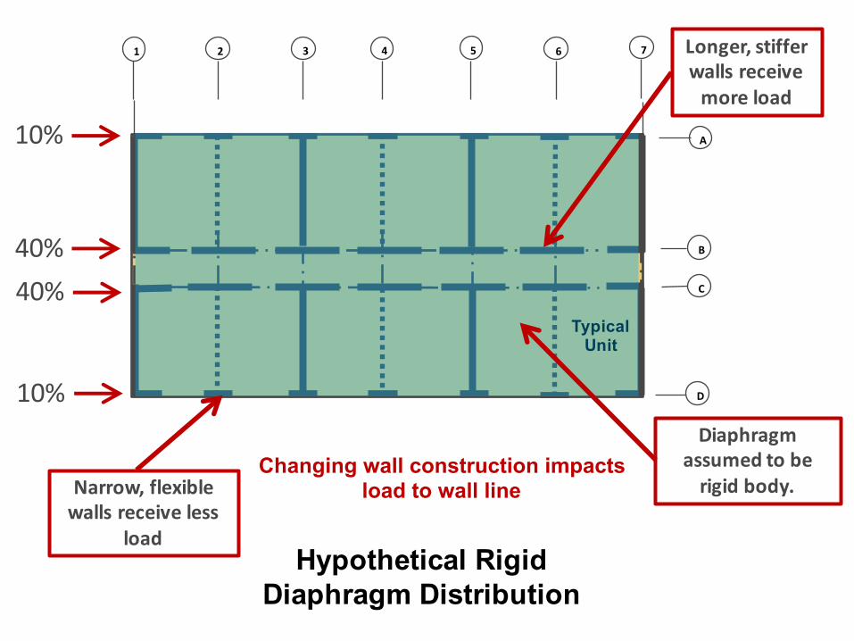
Hypothetical RigidDiaphragm Distribution
Typical Unit
7654321
D
C
B
A
Longer,stifferwallsreceivemoreload
Diaphragmassumedtoberigidbody.
10%
10%
40%
40%
Narrow,flexiblewallsreceiveless
load
Changing wall construction impacts load to wall line
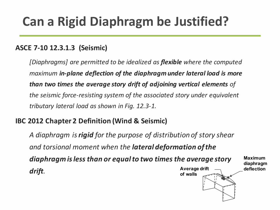
ASCE7-1012.3.1.3(Seismic)
[Diaphragms]arepermittedtobeidealizedasflexible wherethecomputedmaximumin-planedeflectionofthediaphragmunderlateralloadismorethantwotimestheaveragestorydriftofadjoiningverticalelementsoftheseismicforce-resistingsystemoftheassociatedstoryunderequivalenttributarylateralloadasshowninFig.12.3-1.
IBC2012Chapter2Definition(Wind&Seismic)
Adiaphragmisrigid forthepurposeofdistributionofstoryshearandtorsionalmomentwhenthelateraldeformationofthediaphragmislessthanorequaltotwotimestheaveragestorydrift.
CanaRigidDiaphragmbeJustified?
Average drift of walls
Maximum diaphragm deflection
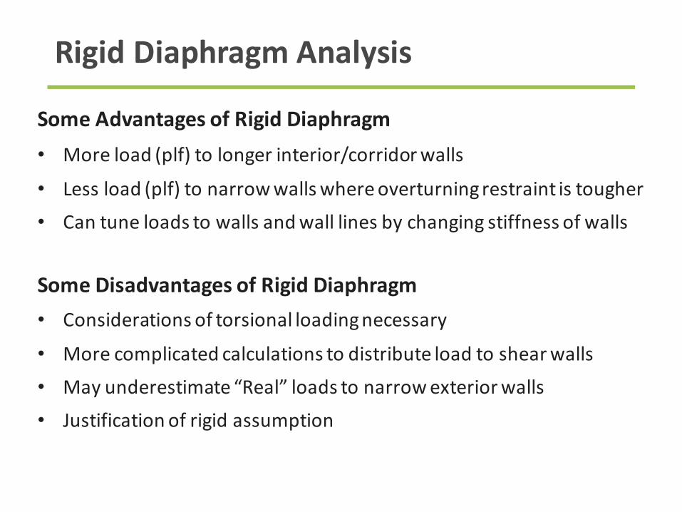
SomeAdvantagesofRigidDiaphragm
• Moreload(plf)tolongerinterior/corridorwalls
• Lessload(plf)tonarrowwallswhereoverturningrestraintistougher
• Cantuneloadstowallsandwalllinesbychangingstiffnessofwalls
SomeDisadvantagesofRigidDiaphragm
• Considerationsoftorsionalloadingnecessary
• Morecomplicatedcalculationstodistributeloadtoshearwalls
• Mayunderestimate“Real”loadstonarrowexteriorwalls
• Justificationofrigidassumption
RigidDiaphragmAnalysis
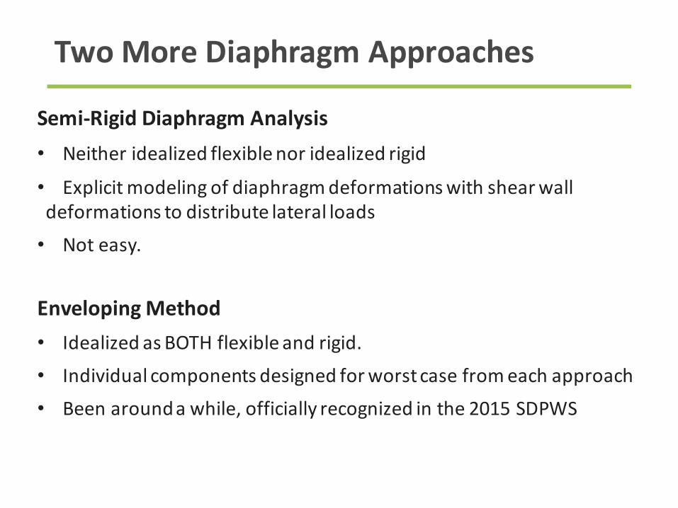
Semi-RigidDiaphragmAnalysis
• Neitheridealizedflexiblenoridealizedrigid
• Explicitmodelingofdiaphragmdeformationswithshearwall
deformationstodistributelateralloads
• Noteasy.
EnvelopingMethod
• IdealizedasBOTHflexibleandrigid.
• Individualcomponentsdesignedforworstcasefromeachapproach
• Beenaroundawhile,officiallyrecognizedinthe2015SDPWS
TwoMoreDiaphragmApproaches

Possible Shear Wall Layouts
Typical Unit
7654321
D
C
B
A
TheCantileverDiaphragmOption
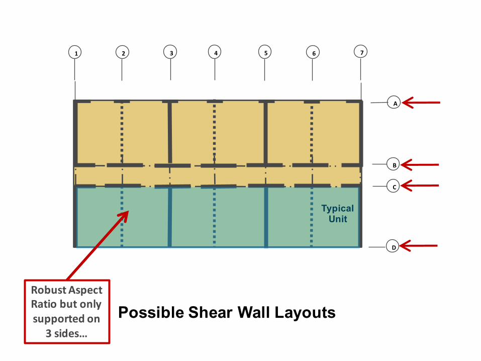
Possible Shear Wall Layouts
Typical Unit
7654321
D
C
B
A
RobustAspectRatiobutonlysupportedon
3sides…

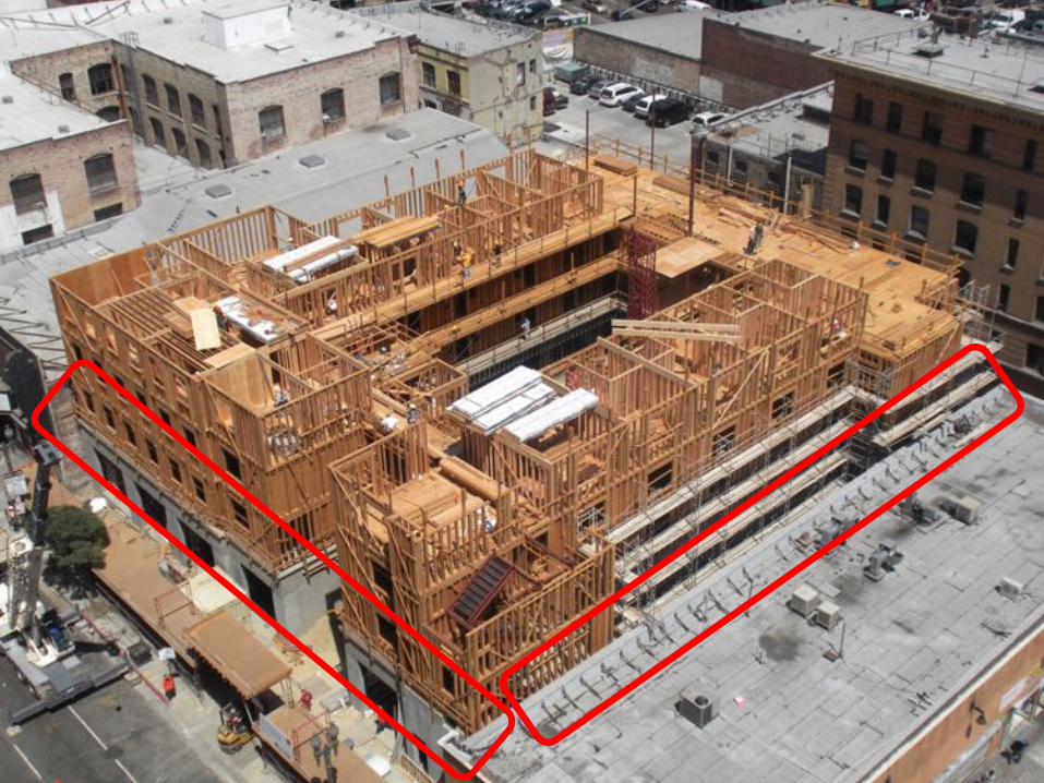
OpenFrontStructure CantileverDiaphragm
CantileveredDiaphragmsinSDPWS2008
AWCSDPWS2008Figure4A
AWCSDPWS2008Figure4B
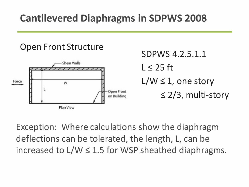
OpenFrontStructure
SDPWS4.2.5.1.1
L≤25ft
L/W≤1,onestory
≤2/3,multi-story
CantileveredDiaphragmsinSDPWS2008
Exception:Wherecalculationsshowthediaphragm
deflectionscanbetolerated,thelength,L,canbe
increasedtoL/W≤1.5forWSPsheatheddiaphragms.

CantileveredDiaphragm
SDPWS4.2.5.2
Lc ≤25ft
Lc/W≤2/3
CantileveredDiaphragmsinSDPWS2008
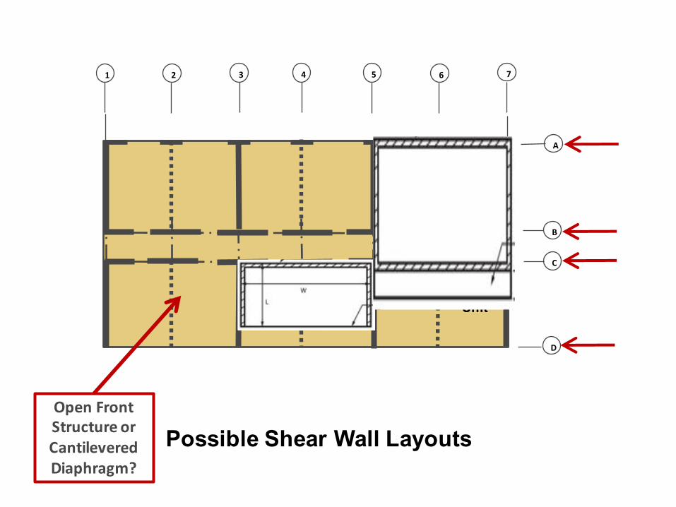
Possible Shear Wall Layouts
Typical Unit
7654321
D
C
B
A
OpenFrontStructureorCantileveredDiaphragm?
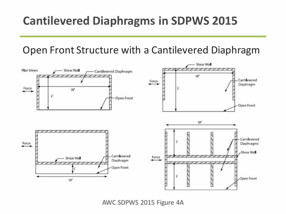
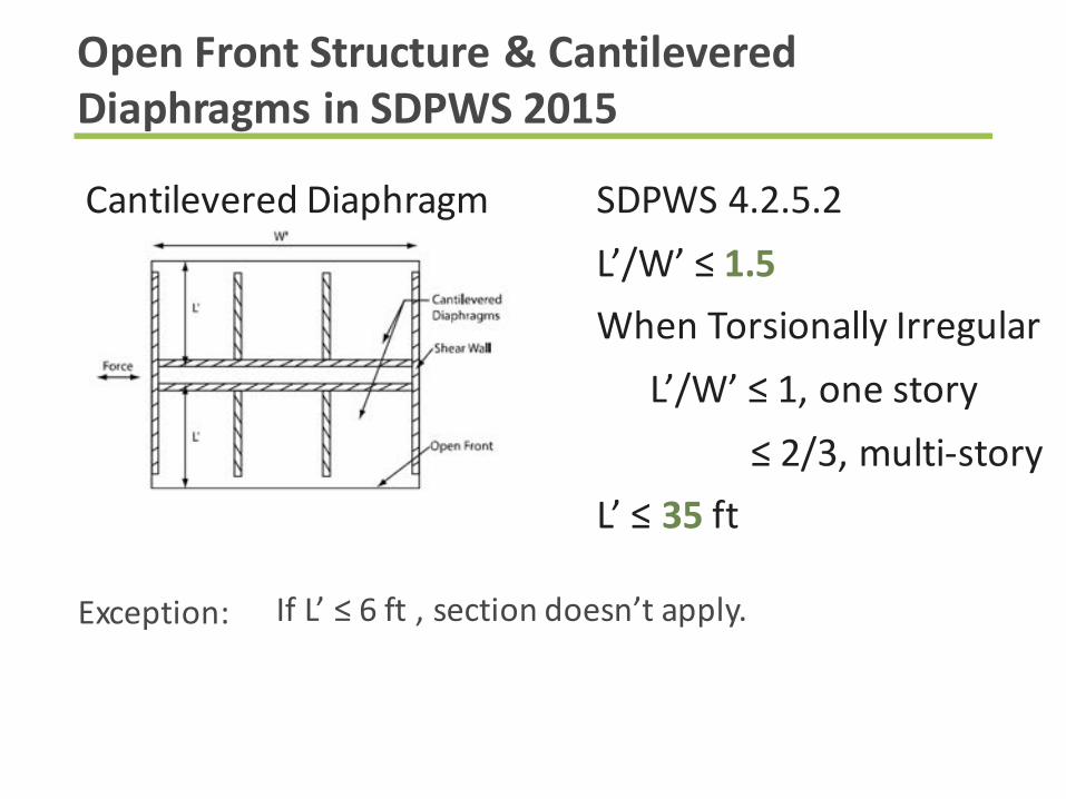
CantileveredDiaphragmsinSDPWS2015
OpenFrontStructurewithaCantileveredDiaphragm
AWCSDPWS2015Figure4A

CantileveredDiaphragm SDPWS4.2.5.2
L’/W’≤1.5
WhenTorsionally Irregular
L’/W’≤1,onestory
2/3,multi-story
L’≤35 ft
OpenFrontStructure&CantileveredDiaphragmsinSDPWS2015
Provideddiaphragmsmodelledasrigidorsemi-rigidandfor
seismic,thestorydriftateachedgeofthestructurewithin
allowablestorydriftofASCE7.Storydriftsincludetorsionand
accidentaltorsionalloadsanddeformationsofthediaphragm.
CantileveredDiaphragm SDPWS4.2.5.2
L’/W’≤1.5
WhenTorsionally Irregular
L’/W’≤1,onestory
≤2/3,multi-story
L’≤35 ft
OpenFrontStructure&CantileveredDiaphragmsinSDPWS2015
IfL’≤6ft ,sectiondoesn’tapply.Exception:
WindLoadDistributiontoShearwalls

TieDownAttachmenttoConcrete
Source:Strongtie
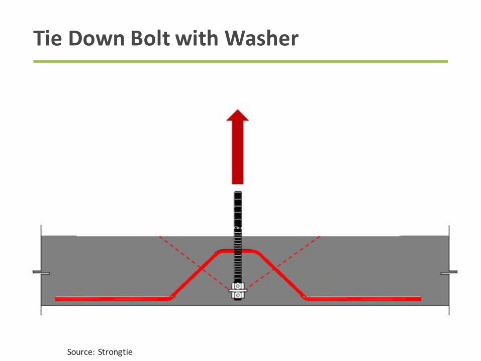
TieDownBoltwithWasher
Source:Strongtie
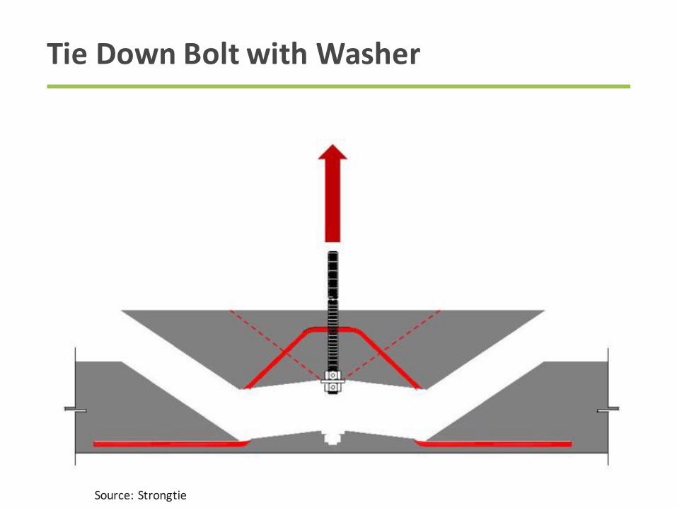
TieDownBoltwithWasher
Source:Strongtie

TieDownBoltwithWasher- Reinforcing
Source:Strongtie

TieDownAnchorChairinCastSlab
Source:EarthboundAnchors

ReinforcingAroundAnchorChairs
Source:EarthboundAnchors

EmbeddedSteelPlates– WeldonRods

TieDownAnchors– PrecastThroughBolt
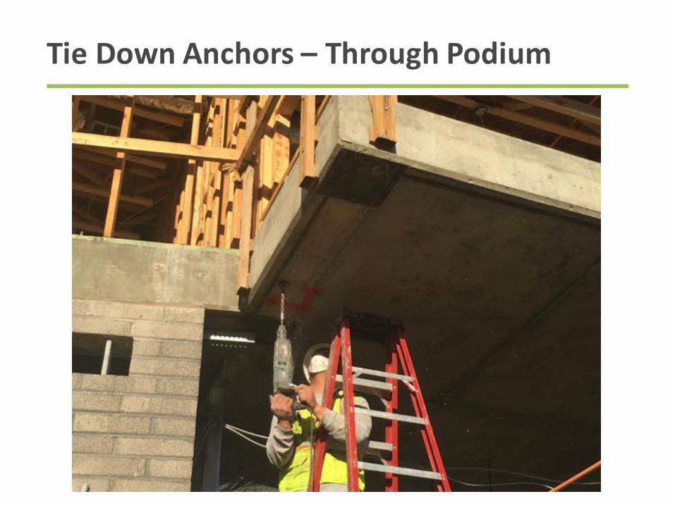
TieDownAnchors– ThroughPodium

DiscontinuousShearWalls
Photocredit:MattTodd&PBArchitects
Karuna IHolst Architecture
Photo: Terry Malone

LateralLoadPathContinuity:WallElevation
ShearWall
ShearWall
Header
Header
Headerdistributes
uppershearwall
endpost
concentratedload
towallbelow
Headeralso
distributesupper
shearwallshearto
wallbelow
Postsinlower
walltransfer
upperwallend
post
concentrated
loadsto
foundation
Wallplatesactas
dragstrutsto
transfershear
loadsfromupper
walltolower
wall
Note:anymember
supporting a
discontinuous wall
mustbedesigned for
theover-strength
factorunderASCE7-
10Section12.3.3.3,
forSDCB-F

OffsetShearWallOverturningResistance
Source:FEMA55
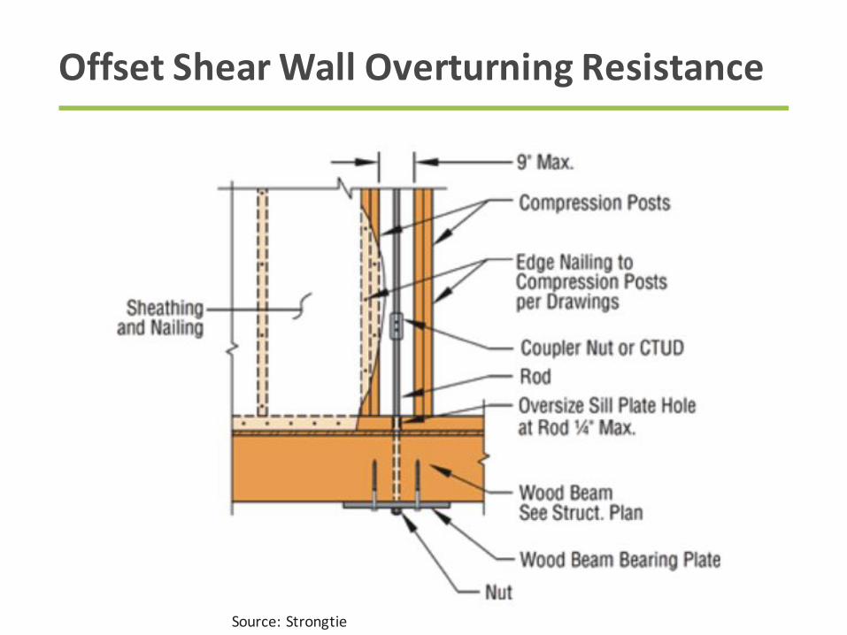
OffsetShearWallOverturningResistance
Source:Strongtie
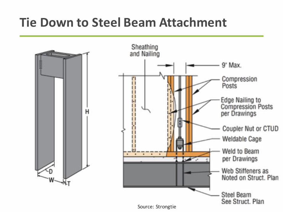
TieDowntoSteelBeamAttachment
Source:Strongtie

TieDowntoSteelBeamAttachment
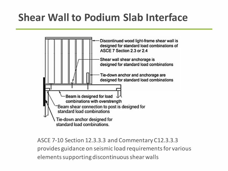
ShearWalltoPodiumSlabInterface
ASCE7-10Section12.3.3.3andCommentaryC12.3.3.3
providesguidanceonseismicloadrequirementsforvarious
elementssupportingdiscontinuousshearwalls
Recap
• WindLoadPaths
• Multi-StoryStackedShearWallEffects
• AccumulationofOverturningLoads
• ShearWallDeflection
• DiaphragmModeling
• DiscontinuousShearWalls

Questions?
ThisconcludesThe
AmericanInstituteof
ArchitectsContinuing
EducationSystems
Course
RickyMcLain,MS,PE,SE
WoodWorks
(802)498-3310
Visitwww.woodworks.org formoreeducationalmaterials,casestudies,designexamples,aprojectgallery,andmore

ThispresentationisprotectedbyUS
andInternationalCopyrightlaws.
Reproduction,distribution,displayanduseof
thepresentationwithoutwrittenpermission
ofthespeakerisprohibited.
©TheWoodProductsCouncil2017
CopyrightMaterials