MULTI PURPOSE UNIT OPTIONS SPECIFICATIONS - … Purpose Body... · 4.4 100 Litre 5mm Air Pressure...
36
Flocon Engineering P/L. Multi-Purpose Unit Specifications. - 1 -. ACN 006 129 040 ABN 19 006 129 040 29 - 31 Apollo Drive, Hallam, Victoria, 3803. Phone: (03) 9703 2777 Fax: (03) 9703 2933 MULTI PURPOSE UNIT OPTIONS SPECIFICATIONS
Transcript of MULTI PURPOSE UNIT OPTIONS SPECIFICATIONS - … Purpose Body... · 4.4 100 Litre 5mm Air Pressure...
Flocon Engineering P/L. Multi-Purpose Unit Specifications. - 1 -.
ACN 006 129 040
ABN 19 006 129 040
29 - 31 Apollo Drive, Hallam, Victoria, 3803.
Phone: (03) 9703 2777 Fax: (03) 9703 2933
MULTI PURPOSE UNIT OPTIONS SPECIFICATIONS

Flocon Engineering P/L. Multi-Purpose Unit Specifications. - 2 -.
FLOCON OPTIONS SPECIFICATIONS
1 Body Weighing System up to 16000kg GVM.
Elphinstone 4 off, Model 510 load cells, fitted to the Flocon body with
brackets to suit. Digital cabin read out only of exact body payload.
2 Hydraulic Component Options
2.1 Flocon Body Auxiliary Engine Hydraulic Drive.
(in lieu of Transmission PTO & Pump or Engine, Auto Transmission live Drive)
Independent body hydraulic power source to the traditional transmission
PTO and pump or Live engine, auto live drives and hydraulic pumps.
12.5hp Kubota horizontal 4-cycle single cylinder diesel engine.
Maximum Output: 12.5hp@2400 rpm.
9.33kW@2400 rpm.
Maximum Torque: 4.04kgf@1800 m/rpm.
2.2 Hydraulic Power Tool Reel.
Our power-pak capable of operating a large range of hydraulic tools.
The power-pak consists of the following;
A hydraulic hose reel with twin high pressure hoses. The hose reel
features a spring rewind system for ease of hose retraction.
The hose is 8 metres long and is assembled within a protective hose
sheath.
The power-pak hoses includes H.T.M.A approved flush face
quick release couplings.
Supplied with a hydraulic oil cooler together with DC electric
fan as part of each hydraulic power-pak system.
Heat generation is a tool characteristic and cooling is necessary to
maintain correct oil temperature for the tool and the operator.
(HPTR is compatible with Stanley Hydraulic Hand Held Tools)
Flocon Engineering P/L. Multi-Purpose Unit Specifications. - 3 -.
FLOCON OPTIONS SPECIFICATIONS
2 Hydraulic Component Options (continued)
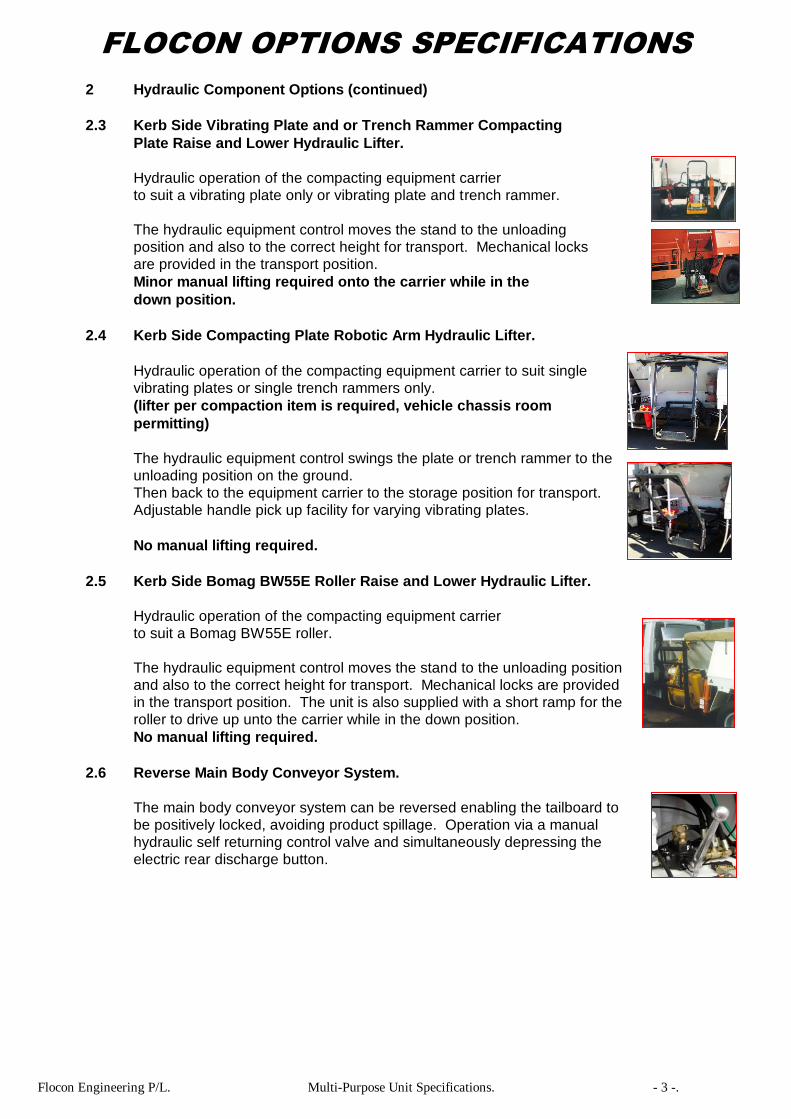
2.3 Kerb Side Vibrating Plate and or Trench Rammer Compacting
Plate Raise and Lower Hydraulic Lifter.
Hydraulic operation of the compacting equipment carrier
to suit a vibrating plate only or vibrating plate and trench rammer.
The hydraulic equipment control moves the stand to the unloading
position and also to the correct height for transport. Mechanical locks
are provided in the transport position.
Minor manual lifting required onto the carrier while in the
down position.
2.4 Kerb Side Compacting Plate Robotic Arm Hydraulic Lifter.
Hydraulic operation of the compacting equipment carrier to suit single
vibrating plates or single trench rammers only.
(lifter per compaction item is required, vehicle chassis room
permitting)
The hydraulic equipment control swings the plate or trench rammer to the
unloading position on the ground.
Then back to the equipment carrier to the storage position for transport.
Adjustable handle pick up facility for varying vibrating plates.
No manual lifting required.
2.5 Kerb Side Bomag BW55E Roller Raise and Lower Hydraulic Lifter.
Hydraulic operation of the compacting equipment carrier
to suit a Bomag BW55E roller.
The hydraulic equipment control moves the stand to the unloading position
and also to the correct height for transport. Mechanical locks are provided
in the transport position. The unit is also supplied with a short ramp for the
roller to drive up unto the carrier while in the down position.
No manual lifting required.
2.6 Reverse Main Body Conveyor System.
The main body conveyor system can be reversed enabling the tailboard to
be positively locked, avoiding product spillage. Operation via a manual
hydraulic self returning control valve and simultaneously depressing the
electric rear discharge button.

Flocon Engineering P/L. Multi-Purpose Unit Specifications. - 4 -.
FLOCON OPTIONS SPECIFICATIONS
3 Body Storage Compartments.
3.1 0.25 – 0.5m3 Side Grit/Sand Bin.
A grit or sand bin fitted in the side of the body located on the
right/left side of the body.
The bin is loaded by shovel and unloaded via a single shovel tray.
3.2 1.0m3 Single or Dual Product Front Grit/Sand Bin.
A grit/sand bin is fitted in the front of the body.
The bin is loaded by machine and emptied via one or two
shovel trays located on both sides of the body.
The bin is sealed with a one piece lid, hydraulically
operated at ground level.
3.3 1.0m3 Single or Dual Product Rear Grit/Sand Bin.
A grit/sand bin is fitted in the rear of the body. The bin is loaded by machine
and emptied via one or two shovel trays located on both sides of the body.
The bin is sealed with a one piece lid, hydraulically operated at ground level.
Additional Rear Singular or Dual Product Storage Bin Manual Hydraulically Operated
Left & Right Rear Shovel Outlets Fitted Only When Rear Spreaders are not Required
Left & Right Side Shovel Outlets Fitted Only When Rear Spreaders are Required

Flocon Engineering P/L. Multi-Purpose Unit Specifications. - 5 -.
FLOCON OPTIONS SPECIFICATIONS
3 Body Storage Compartments. (continued)
3.4 0.25 – 0.5m3 Side Gravity Unloading Spoil Bin.
A spoil bin is built onto the right/left side of the body.
The floor of bin is constructed from 3 mm steel and
angled at approximately 40 degrees to allow material
to run out when the gate is opened.
3.5 0.25 – 0.5m3 Hydraulic Side Tipping Spoil Bin.
A side tipping spoil bin mounted on the right/left side of the body.
The bin is unloaded hydraulically.
3.6 1.0 – 2.0m3 Hydraulic Side Tipping Spoil Bin.
A side tipping spoil bin mounted between the front of the body
and rear of the cabin at full cabin width.
The spoil bin tips to the right/left of the vehicle by hydraulic
controls.
3.7 0.25-0.5m3 Hydraulic Ground Level Spoil Lifter.
A hydraulic operated ground level loading side lifter connected to the
main side tipping spoil bin decreases the lifting height of spoil into
the side tipping spoil bin. The lifter is fitted to left or right depending
on which way the side tipping spoil bin is to unload. It is loaded by hand
and hydraulic raised to unload into the main side tipping spoil bin.
3.8 2000 mm Lockable Storage Tray.
A lockable storage tray constructed on the right/left side of the body.
The locker is a minimum of 2 metres in length. The locker is fitted with
Gas Struts to assist opening the lid and ‘T’’ bar type locking handles.
The storage locker is fitted with plastic weather-proof hinge.
3.9 Forward Mounted Storage Locker.
A forward mounted storage lockable is fitted between the vehicle cabin
and body.
The locker is a minimum of 2.4 metres in length,
1 metre high x 500mm wide.
The locker is fitted ‘T’’ bar type locking handles opening sideways.
The storage locker is fitted with a rubber water proof seal.

Flocon Engineering P/L. Multi-Purpose Unit Specifications. - 6 -.
FLOCON OPTIONS SPECIFICATIONS
4 Water Tanks.
4.1 60 Litre Drinking Poly Plastic Water Tank.
A poly plastic water drinkable tank.
4.2 30 Litre Hand wash & Drinking Poly Water Tank.
A 23 litre poly water tank with hand wash facility.
4.3 1-200 Litre Stainless Steel Water Tank.
A 1-200 litre 2mm stainless steel water tank in lieu of the standard
100 litre tank.
4.4 100 Litre 5mm Air Pressure Water Vessel.
A 100 litre 5mm steel air pressure vessel water tank in lieu of the standard
100 litre tank. Registered pressure vessel certificates supplied, with all
safety valves as required.
100 Litre Tank Dimensions:
375 mm diameter. 800 shell length. (1000 mm overall length)
Class 2B Transportable. 800 kpa.
4.5 200 Litre 5mm Air Pressure Water Vessel.
(Room Permitting Long Wheelbase Units Preferred)
A 200 litre 5mm steel air pressure vessel water tank in lieu of the
Standard 200 litre tank. Registered pressure vessel certificates supplied,
with all safety valves as required.
200 Litre Tank Dimensions:
610 mm diameter. 513 shell length. (900 mm overall length)
Class 2B Transportable. 800 kpa.
4.6 Air Water System Controls.
Air inlet gauge. Tank air gauge. Tank outlet gauge.
Air pressure regulator. Air pressure relief valve.
1400ci auxiliary air receiver. Yellow air safety placard.
All mounted into a external control panel.

Flocon Engineering P/L. Multi-Purpose Unit Specifications. - 7 -.
FLOCON OPTIONS SPECIFICATIONS
5 Water and Chemical Spraying Systems
5.1 Electric Water Spray System and Plastic Hose Reel.
A electric water pump is fitted below the tank and connected
to a 10 metre water hose on a self retracting plastic hose reel,
spray gun. The spray gun has a adjustable fan nozzle.
5.2 Hydraulic Spray System and Plastic Hose Reel.
A hydraulically driven water pump is fitted below the tank and
connected to a 10 metre water hose on a self retracting plastic
hose reel, spray gun. The spray gun has a adjustable fan
nozzle.
5.3 Chemical Spray System and Steel Hose Reel.
A electric chemical pump is fitted below the tank and
connected to a 6 metre chemical hose on a self retracting
steel hose reel, spray gun.
The spray gun has a adjustable fan nozzle.
5.4 Combination Water and Chemical Spray System Including Hose Reel.
A electric chemical pump is fitted below the tank and connected to a
spray gun and 3 way diversion tap.
The 3 way tap when adjusted can either move water or chemicals
through the hose. The spray gun has a adjustable fan nozzle.
A steel retractable hose reel with 6 metres of hose is supplied
and fitted in an accessible position.
6 Emulsion Systems and Tanks.
6.1 1000 Litre Gravity Emulsion Tank.
Our offer includes the supply of a OH & S Authority
approved 500-1000 litre emulsion storage tank fitted
between the vehicle cabin and body. Access steps and
standing platform to fill from included.
The emulsion tank is supplied with large inspection
plates and accessible filler neck for cleaning and inspection
requirements. The tank is not subject to any air pressure to move emulsion.
6.1.1 Connection Integral Cleaning Tank to Emulsion Pump.
Our offer includes valves and hosing from the integral
manufactured tank as part of the emulsion tank, for
cleaning the emulsion lines, reel and lance.

Flocon Engineering P/L. Multi-Purpose Unit Specifications. - 8 -.
FLOCON OPTIONS SPECIFICATIONS
6 Emulsion Systems and Tanks. (continued)
6.1.2 Level System to Suit Gravity Emulsion Tanks Only.
The level system consists of a 1-litre nitrile accumulator bladder
mounted near the bottom of the emulsion tank connected to a
plastic pipe which runs up above the height of the tank.
The bladder is filled with a non-toxic environmentally safe fluid
with specific gravity similar to the emulsion. As the tank is filled,
the fluid is displaced from the bladder into the plastic sight gauge.
The level on the pipe follows the level of the fluid in the tank.
6.1.3 High Volume Gravity Pump System Suit 15 Nozzle Emulsion Spray Bar.
The high volume gravity pressure pump system features the reliable
impeller centrifugal pump with teflon gland packing.
This packing is suitable for use with emulsion, kerosene, etc.
The pump is operated by a hydraulic motor coupled to the pump. High volume open impeller 112 Flocon emulsion pump only.
RPM: 3000.
Pressure: 100 kpa.
Flow: 300 lpm.
Tank to Pump Hose Size: 50.0 mm
Pump to Bar Hose Size: 38.0 mm
Coverage up to: 2.0 lt per m2
6.2 500–1000 Litre Air Emulsion Tank.
A air emulsion system of 500/1000 lts. in capacity is supplied with
registered pressure vessel certificates. Pricing for larger capacities
are determined at time of purchase.
6.2.1 Air Emulsion System 20cfm Air Compressor.
Required for Air Pressure Vessels Over 205 litre Capacity.
An independent 20cfm 3 cyinder air compressor is supplied driven by a hydraulic motor operating independent of the vehicle brake system. A reserve air tank is also supplied to keep constant pressure to the emulsion air pressure vessel. A filling facility from drums is also available if required.
6.2.2 Air Emulsion System Controls.
Air inlet gauge.
Tank air gauge.
Tank outlet gauge.
Air pressure regulator.
Air pressure relief valve.
1400ci auxiliary air receiver.
Yellow air safety placard.
All mounted into a external control panel.

Flocon Engineering P/L. Multi-Purpose Unit Specifications. - 9 -.
FLOCON OPTIONS SPECIFICATIONS
6 Emulsion Systems and Tanks. (continued)
6.3 240 Volt Overnight Emulsion Tank Heating. Our offer includes 240 volt up to 40 degrees Celsius heating,
thermostatically controlled emulsion heating for overnight use and fitted with a digital temperature gauge and thermometer.
6.4 Water Tank Heating. (Tanks mounted behind vehicle cabins only)
Our offer includes a an inlet and outlet water tube fitted into the lower part of the emulsion tank for heating of emulsion. Digital temperature readout. This system uses the water from the truck radiator and will automatically keep the tank heated at the preset temperature selected via the pneumatically operated ball valve and thermostat control. All aspects of safety are supplied to protect the engine in case of water leakage.
6.5 Inline Water Heat Exchanger. (Hand spraying only)
Our offer includes a stainless steel heat exchanger which allows Radiator water and emulsion to run side by, side warming the emulsion on its way to the spray lance.
This system uses the water from the truck radiator and all aspects of Safety are supplied to protect the engine in case of water leakage.
6.6 Emulsion Tank Filter Strainer Top Fill.
Tank inlet box type strainer, for top filling.
6.7 Emulsion Tank Filter Strainer Bottom Fill.
2” camlock connection with inbuilt removable strainer, including
2” ball valve, for bottom filling.
6.8 Replacement Filters Bottom Fill.
Supply of inbuilt spare removable strainer only.

Flocon Engineering P/L. Multi-Purpose Unit Specifications. - 10 -.
FLOCON OPTIONS SPECIFICATIONS
7 Emulsion Spray Bars. 7.1 Emulsion Spray Bars Designed for Usage In Conjunction with the Paving Unit. 7.1.1 300mm Nozzle Spacing 2.5 Metre CRS Emulsion Spray Bar Manual Nozzle Isolation Only.
A 7 nozzle 2.5 metre wide spray bar with an electric/air control operated from the vehicle cabin. Application for accurate emulsion seals up from 0.1 to 1.0 litres per square metre. The 7 nozzles can be isolated individually, manual nozzle isolation only. Facility to clean spray bar only.
Full width front of bar anti splash rubber matting. 7.1.2 300mm Nozzle Spacing 2.5 Metre CRS Emulsion Spray Bar.
Electric Air Operated Nozzle Isolation Only.
A 7 nozzle 2.5 metre wide spray bar with individual electric air operated nozzles. 7 individual switches are located at the rear of the body, with a Master auto switch. Select nozzles from 1-7 in any order then select the Master auto switch, this switch transfers all the selected nozzles to the control switch located in the vehicle cabin. Application for accurate emulsion seals up from 0.1 to 1.0 litres per square metre. Facility to clean spray bar only.
Full width front of bar anti splash rubber matting. 7.2 Emulsion Spray Bars Designed for Usage In Conjunction with the Aggregate Spreader. 7.2.1 150mm Nozzle Spacing 2.5 Metre CRS Emulsion Spray Bar Manual Nozzle Isolation Only.
A 15 nozzle 2.5 metre wide spray bar with an electric/air control operated from the vehicle cabin. Application for accurate emulsion seals up from 1.0 to 2.0 litres per square metre. The 15 nozzles can be isolated individually, manual nozzle isolation only. Facility to clean spray bar only.
7.2.2 150mm Nozzle Spacing 2.5 Metre CRS Emulsion Spray Bar.
Electric Air Operated Nozzle Isolation Only.
A 15 nozzle 2.5 metre wide spray bar with individual electric air operated nozzles. 15 individual switches are located at the rear of the body, with a Master auto switch. Select nozzles from 1-15 in any order then select the Master auto switch, this switch transfers all the selected nozzles to the control switch located in the vehicle cabin. Application for accurate emulsion seals up from1.0 to 2.0 litres per square metre.
Facility to clean spray bar only.
7.3 7-15 Electrically Heated Spray Nozzles for Spray Bars.
7-15 electrically heated spray nozzles, heated to 70 degrees
celcius, when required. Eliminates the use of chemical fluid to
clean the nozzles in the emulsion spray bar.
7.4 Air Assisted Spray Bar Spraying and Stored Height Adjustment.
Left and right pneumatic cylinders are installed to raise and lower
the spray bar.
7.5 Spray Bar Cleaning System.
A electric or air pump will be fitted below the standard 40 litre emulsion flushing tank and connected to the spray bar for cleaning purposes only.

Flocon Engineering P/L. Multi-Purpose Unit Specifications. - 11 -.
FLOCON OPTIONS SPECIFICATIONS
8 Body Covers.
8.1 Hand Operational Self Winding Body Cover.
Manual ground level self winding bow type cover with heat
treated pvc material supplied fitted with or without side skirts.
8.2 12/24 Volt Electric/Hydraulic Operational Self Winding Body Cover.
Operated from the vehicle cabin by an electric switch,
self winding bow type cover with heat treated
pvc material supplied fitted with or without side skirts.
8.3 Roll Tarp Self Winding Body Cover.
Manual ground level self winding right side to left side cover
with heat treated pvc.
8.4 12/24 Volt Electric Operated Hydraulic Self Opening Body Doors.
Two synchronised doors fully insulated and water proof operated from the
vehicle cabin by an electric switch. External manual hydraulic override installed.
Opening and closing of the doors is by two hydraulic cylinders.
Plant and loader height restrictions can apply.
9 Tow Bars and Cab Chassis Options.
9.1 BT350 50 mm Ball Tow Bars up to 3500 kg Capacity.
A tailored tow bar to suit the Flocon unit chassis supplied with
either a 50 mm ball or tongue style fitted with a 24 Volt 7 pin
socket.
9.2 BT1200H Pintle Hook Tow Bars up to 7000 kg Capacity.
A tailored tow bar to suit the Flocon unit chassis supplied
with a Pintle hook and fitted with a 24 volt 7 pin socket.
9.3 BT1200B 95 mm Bartlett Ball Tow Bars up to 7000 kg Capacity.
A tailored tow bar to suit the Flocon unit chassis supplied with a
95 mm Bartlett ball and fitted with a 24 volt 7 pin socket.
9.4 BT1250H 3500 kg 50 mm Ball & 7000 kg Pintle Hook Tow Bars.
A tailored tow bar to suit the Flocon unit chassis supplied with a
Hayman Reese square socket and removable 50 mm ball and
fixed 7000 kg pintle hook. A 24 volt 7 pin socket is also fitted.

Flocon Engineering P/L. Multi-Purpose Unit Specifications. - 12 -.
FLOCON OPTIONS SPECIFICATIONS
9 Tow Bars and Cab Chassis Options. (Continued)
9.5 Multi-Hitch 3500 kg 50 mm Ball & 7000 kg Pintle Hook Tow Bars.
A tailored tow bar to suit the Flocon unit chassis supplied with a
Multi-Hitch 50 mm ball and fixed 7000 kg combination pintle hook.
A 24 volt 7 pin socket is also fitted.
9.6 BT1300B 127 mm Bartlett Ball Tow Bars up to 13000 kg Capacity.
A tailored tow bar to suit the Flocon unit chassis supplied with a
127 mm Bartlett ball and fitted with a 24 volt 7 pin socket.
9.7 BT1400B 127 mm Bartlett Ball Tow Bars up to 24000 kg Capacity.
A tailored tow bar to suit the Flocon unit chassis supplied with a
127 mm Bartlett ball and fitted with a 24 volt 7 pin socket.
9.8 Westinghouse Foot Control Only Air Trailer Brake System.
Westinghouse foot control only air trailer brake system, colour coded.
Including dust covers for couplings.
9.9 24-Volt –12 Volt Basic Reducer Suit 12 Volt Trailer Lights.
Basic 24-12 volt trailer light reducer.
9.10 12 Volt Trailer Brake Controller.
A cabin mounted 12 volt trailer brake controller is fitted for trailers with
electric brakes, including trailer base socket.
9.11 24 Volt Trailer Brake Controller.
A cabin mounted 12 volt trailer brake controller and 24-12 volt voltage
reducer is fitted for trailers with electric brakes, including trailer base socket.
9.12 Wheelbase Shortening as Required.
Including tail shaft alterations and engineering certificates for registration.
9.13 Wheelbase Extension 400mm Plus.
Including additional tail shaft and engineering certificates for registration.
10 Two Man Sandbagging Attachment.
A quick release attachment for the rear of the Flocon body to enable filling of sand bags by two men. The Flocon unit will need to be located on a ramp to allow the two men at the rear of the unit to stand straight. (The vehicle will require to be placed on a ramp)
11 Rear Swing Wheelbarrow Carrier and Wheelbarrow.
A hinged wheelbarrow carrier is fitted to the rear of the body enabling the barrow to be carried and hinged to allow material spreading if required. A sturdy wheelbarrow is also supplied to suit the carrier.
Flocon Engineering P/L. Multi-Purpose Unit Specifications. - 13 -.
FLOCON OPTIONS SPECIFICATIONS
12 Alloy Hand Rakes and Screeds. Choice of 300-600mm alloy rake or screed or combination, rake and screed.
13 Warning System Options.
‘A’ Type Incandescent Lamp Arrow Boards conforming to Australian & RTA Standard.
(12/24 Volt Linak Actuators Only Used When Air is not Available on the Cab Chassis)
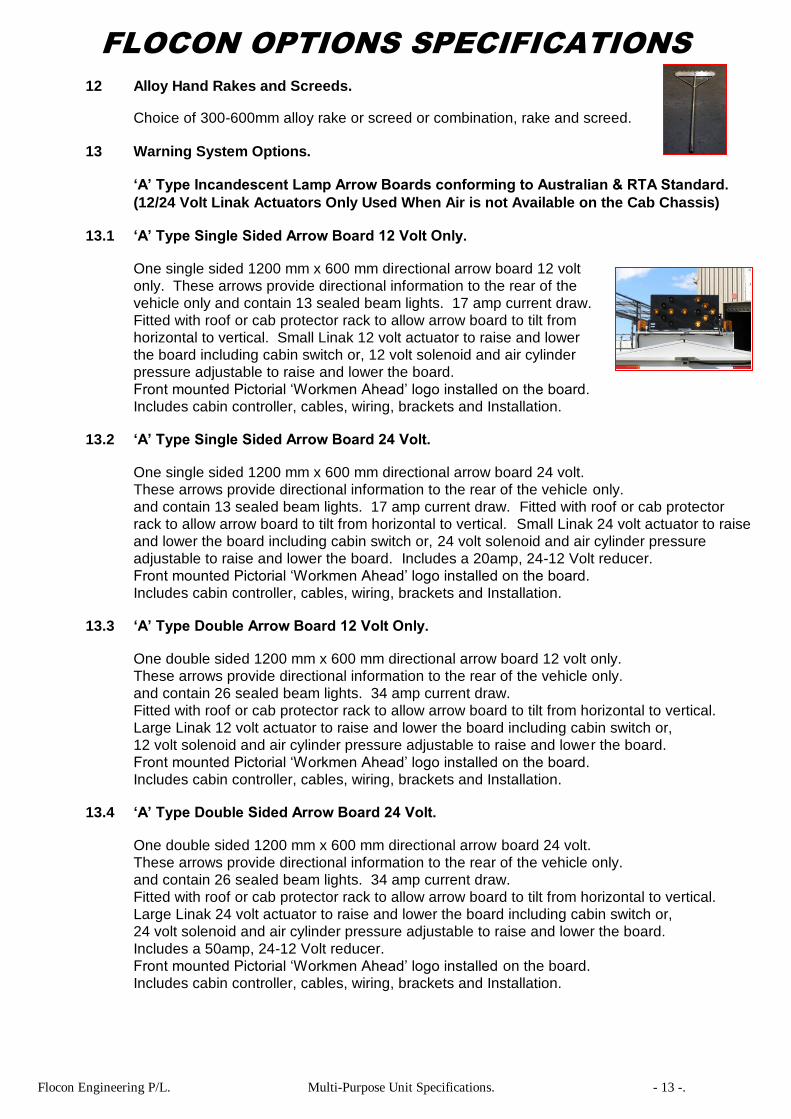
13.1 ‘A’ Type Single Sided Arrow Board 12 Volt Only.
One single sided 1200 mm x 600 mm directional arrow board 12 volt
only. These arrows provide directional information to the rear of the
vehicle only and contain 13 sealed beam lights. 17 amp current draw.
Fitted with roof or cab protector rack to allow arrow board to tilt from
horizontal to vertical. Small Linak 12 volt actuator to raise and lower
the board including cabin switch or, 12 volt solenoid and air cylinder
pressure adjustable to raise and lower the board.
Front mounted Pictorial ‘Workmen Ahead’ logo installed on the board.
Includes cabin controller, cables, wiring, brackets and Installation.
13.2 ‘A’ Type Single Sided Arrow Board 24 Volt.
One single sided 1200 mm x 600 mm directional arrow board 24 volt.
These arrows provide directional information to the rear of the vehicle only.
and contain 13 sealed beam lights. 17 amp current draw. Fitted with roof or cab protector
rack to allow arrow board to tilt from horizontal to vertical. Small Linak 24 volt actuator to raise
and lower the board including cabin switch or, 24 volt solenoid and air cylinder pressure
adjustable to raise and lower the board. Includes a 20amp, 24-12 Volt reducer.
Front mounted Pictorial ‘Workmen Ahead’ logo installed on the board.
Includes cabin controller, cables, wiring, brackets and Installation.
13.3 ‘A’ Type Double Arrow Board 12 Volt Only.
One double sided 1200 mm x 600 mm directional arrow board 12 volt only.
These arrows provide directional information to the rear of the vehicle only.
and contain 26 sealed beam lights. 34 amp current draw.
Fitted with roof or cab protector rack to allow arrow board to tilt from horizontal to vertical.
Large Linak 12 volt actuator to raise and lower the board including cabin switch or,
12 volt solenoid and air cylinder pressure adjustable to raise and lower the board.
Front mounted Pictorial ‘Workmen Ahead’ logo installed on the board.
Includes cabin controller, cables, wiring, brackets and Installation.
13.4 ‘A’ Type Double Sided Arrow Board 24 Volt.
One double sided 1200 mm x 600 mm directional arrow board 24 volt.
These arrows provide directional information to the rear of the vehicle only.
and contain 26 sealed beam lights. 34 amp current draw.
Fitted with roof or cab protector rack to allow arrow board to tilt from horizontal to vertical.
Large Linak 24 volt actuator to raise and lower the board including cabin switch or,
24 volt solenoid and air cylinder pressure adjustable to raise and lower the board.
Includes a 50amp, 24-12 Volt reducer.
Front mounted Pictorial ‘Workmen Ahead’ logo installed on the board.
Includes cabin controller, cables, wiring, brackets and Installation.

Flocon Engineering P/L. Multi-Purpose Unit Specifications. - 14 -.
FLOCON OPTIONS SPECIFICATIONS
13 Warning System Options.
‘B’ Type Incandescent Lamp Arrow Boards conforming to Australian & RTA Standard.
13.5 ‘B’ Type Single Sided Arrow Board 12 Volt Only. $ 4,800.00
GST Component. $ 480.00
Inclusive GST Pricing. $ 5,280.00
One single sided 1500 mm x 750 mm directional arrow board 12 volt
only. These arrows provide directional information to the rear of the
vehicle only and contain 15 sealed beam lights. 38 amp current draw.
Fitted with roof or cab protector rack to allow arrow board to tilt from
horizontal to vertical. 12 volt solenoid and air cylinder pressure
adjustable to raise and lower the board.
Front mounted Pictorial ‘Workmen Ahead’ logo installed on the board.
Includes cabin controller, cables, wiring, brackets and Installation.
13.6 ‘B’ Type Single Sided Arrow Board 24 Volt. $ 5,300.00
GST Component. $ 530.00
Inclusive GST Pricing. $ 5,830.00
One single sided 1500 mm x 750 mm directional arrow board 24 volt.
These arrows provide directional information to the rear of the vehicle only.
and contain 15 sealed beam lights. 38 amp current draw.
Fitted with roof or cab protector rack to allow arrow board to tilt from horizontal to vertical.
24 volt solenoid and air cylinder pressure adjustable to raise and lower the board.
Includes a 20amp, 24-12 Volt reducer.
Front mounted Pictorial ‘Workmen Ahead’ logo installed on the board.
Includes cabin controller, cables, wiring, brackets and Installation.
13.7 ‘B’ Type Double Arrow Board 12 Volt Only. $ 6,800.00
GST Component. $ 680.00
Inclusive GST Pricing. $ 7,480.00
One double sided 1500 mm x 750 mm directional arrow board 12 volt only.
These arrows provide directional information to the rear of the vehicle only.
and contain 30 sealed beam lights. 76 amp current draw. Fitted with roof or cab protector
rack to allow arrow board to tilt from horizontal to vertical. 12 volt solenoid and air cylinder
pressure adjustable to raise and lower the board. Front mounted Pictorial ‘Workmen Ahead’
logo installed on the board. Includes cabin controller, cables, wiring, brackets and Installation.
13.8 ‘B’ Type Double Sided Arrow Board 24 Volt. $ 7,300.00
GST Component. $ 730.00
Inclusive GST Pricing. $ 8,030.00
One double sided 1500 mm x 750 mm directional arrow board 24 volt.
These arrows provide directional information to the rear of the vehicle only.
and contain 30 sealed beam lights. 76 amp current draw. Fitted with roof or cab protector
rack to allow arrow board to tilt from horizontal to vertical. 24 volt solenoid and air cylinder
pressure adjustable to raise and lower the board. Includes two (2) x 50amp, 24-12 Volt
reducers. Front mounted Pictorial ‘Workmen Ahead’ logo installed on the board.
Includes cabin controller, cables, wiring, brackets and Installation.

Flocon Engineering P/L. Multi-Purpose Unit Specifications. - 15 -.
FLOCON OPTIONS SPECIFICATIONS
13 Warning System Options. (Continued)
‘A’ Type LED Arrow Boards.
(12/24 Volt Linak Actuators Only Used When Air is not Available on the Cab Chassis)
13.9 ‘A’ Type LED Single Sided Arrow Board 12/24 Volt.
One single sided 1200 mm x 600 mm directional arrow board 12/24 volt.
These arrows provide directional information to the rear of the vehicle only.
and contain 13 LED lights. 7 amp current draw. Fitted with roof or cab
protector rack to allow arrow board to tilt from horizontal to vertical. Small
Linak 12/24 volt actuator to raise and lower the board including cabin switch
or, 12/24 volt solenoid and air cylinder pressure adjustable to raise and lower
the board. Front mounted Pictorial ‘Workmen Ahead’ logo installed on the
board. Includes cabin controller, cables, wiring, brackets and Installation.
13.10 ‘A’ Type LED Double Sided Arrow Board 12/24 Volt.
One double sided 1200 mm x 600 mm directional arrow board 12/24 volt.
These arrows provide directional information to the rear of the vehicle only.
and contain 26 LED lights. 14 amp current draw. Fitted with roof or cab
protector rack to allow arrow board to tilt from horizontal to vertical.
Large Linak 12 volt actuator to raise and lower the board including cabin
switch or, 12/24 volt solenoid and air cylinder pressure adjustable to raise
and lower the board. Front mounted Pictorial ‘Workmen Ahead’ logo installed
on the board. Includes cabin controller, cables, wiring, brackets and Installation.
13.11 ‘B’ Type LED Single Sided Arrow Board 12/24 Volt.
One single sided 1500 mm x 750 mm directional arrow board 12/24 volt.
These arrows provide directional information to the rear of the vehicle only
and contain 15 LED lights. 8 amp current draw. 12/24 volt solenoid and air
cylinder pressure adjustable to raise and lower the board. Front mounted
Pictorial ‘Workmen Ahead’ logo installed on the board. Includes cabin
controller, cables, wiring, brackets and Installation.
13.12 ‘B’ Type LED Double Sided Arrow Board 12/24 Volt.
One double sided 1500 mm x 750 mm directional arrow board 12/24 volt.
These arrows provide directional information to the rear of the vehicle
only. and contain 30 LED lights. 16 amp current draw. 12/24 volt
solenoid and air cylinder pressure adjustable to raise and lower the board.
Front mounted Pictorial ‘Workmen Ahead’ logo installed on the board.
Includes cabin controller, cables, wiring, brackets and Installation.

Flocon Engineering P/L. Multi-Purpose Unit Specifications. - 16 -.
FLOCON OPTIONS SPECIFICATIONS
13 Warning System Options. (continued) 13.13 Amber 12/24 Volt High Profile Quad Flash Strobe Lights. (In lieu of standard amber beacons) High profile amber double flash strobe lights in 8 or 12 Joules, 70 quad FPM. 13.14 Amber 12/24 Volt Low Profile Quad Flash Strobe Lights. (In lieu of standard amber beacons) Low profile amber double flash strobe lights in 8 or 12 Joules, 70 quad FPM. 13.15 Emergency Stop Body Buttons Each. Large emergency stop button, stops all hydraulic body functions immediately fitted in cabin or at the rear of the body. 14 Reverse Alarms. 14.1 12/24 Volt Reverse Alarm. (In lieu of standard truck reverse alarm) 97 dba fixed mode reverse alarm. 14.2 12/24 Volt Reverse Alarm. (In lieu of standard truck reverse alarm) 77-102 dba self adjusting reverse alarm. 15 Intercom and Safety Cameras. 15.1 Intercom System. Intercom module fitted in the vehicle cabin with external speaker
fitted to the rear of the unit. Enabling the rear operators to communicate with the vehicle driver.
15.2 Colour 5.5” Single Rear Vision Camera System. 12-24 volt 5.0” colour monitor fitted in the vehicle cabin and one rear mounted camera and shutter. Enables the driver to sight all operators in a very wide arc at the rear of the unit. 15.3 Colour Dual Rear Vision Camera System.
12-24 volt 5.0” colour monitor fitted in the vehicle cabin and two mounted cameras. A rear mounted camera enables the driver to sight all operators in a larger arc at the rear of the unit.
The second camera is mounted at the rear of the
body cab protector enabling the operator to see into
the body hopper to check the amount of product that is present.
Flocon Engineering P/L. Multi-Purpose Unit Specifications. - 17 -.
FLOCON OPTIONS SPECIFICATIONS
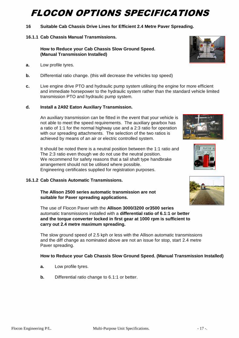
16 Suitable Cab Chassis Drive Lines for Efficient 2.4 Metre Paver Spreading.
16.1.1 Cab Chassis Manual Transmissions.
How to Reduce your Cab Chassis Slow Ground Speed.
(Manual Transmission Installed)
a. Low profile tyres.
b. Differential ratio change. (this will decrease the vehicles top speed)
c. Live engine drive PTO and hydraulic pump system utilising the engine for more efficient
and immediate horsepower to the hydraulic system rather than the standard vehicle limited
transmission PTO and hydraulic pump system.
d. Install a 2A92 Eaton Auxiliary Transmission.
An auxiliary transmission can be fitted in the event that your vehicle is
not able to meet the speed requirements. The auxiliary gearbox has
a ratio of 1:1 for the normal highway use and a 2:3 ratio for operation
with our spreading attachments. The selection of the two ratios is
achieved by means of an air or electric controlled system.
It should be noted there is a neutral position between the 1:1 ratio and
The 2:3 ratio even though we do not use the neutral position.
We recommend for safety reasons that a tail shaft type handbrake
arrangement should not be utilised where possible.
Engineering certificates supplied for registration purposes.
16.1.2 Cab Chassis Automatic Transmissions.
The Allison 2500 series automatic transmission are not
suitable for Paver spreading applications.
The use of Flocon Paver with the Allison 3000/3200 or3500 series
automatic transmissions installed with a differential ratio of 6.1:1 or better
and the torque converter locked in first gear at 1000 rpm is sufficient to
carry out 2.4 metre maximum spreading.
The slow ground speed of 2.5 kph or less with the Allison automatic transmissions
and the diff change as nominated above are not an issue for stop, start 2.4 metre
Paver spreading.
How to Reduce your Cab Chassis Slow Ground Speed. (Manual Transmission Installed)
a. Low profile tyres.
b. Differential ratio change to 6.1:1 or better.

Flocon Engineering P/L. Multi-Purpose Unit Specifications. - 18 -.
FLOCON OPTIONS SPECIFICATIONS
16.2 Hotmix/Premix Paving Units.
16.2.1 2.0 Metre Automatic Operation Hotmix/Premix Footpath Paving Unit.
The paving units function is to spread material to a maximum depth of
150 mm and width from 0.5 metres to 2.0 metres.
The paver is forced to the ground via dual adjustable air pressure
cylinders. Left and right manual blade height adjustments.
2.5 metre left and right adjustable cast iron travel wheels.
Material is fed to the paver via the auto controlled sensor eye.
Adjustable to varying spreading widths.
If Air is available on the Cab Chassis.
12/24 Volt Ultrasonic Sensor to Control Body Conveyor System.
An Ultrasonic Sensor is fitted to the rear Paver back plate with a adjustable
maximum sense range of up to 300mm and minimum sense range of 60mm.
The sensor when fitted and adjusted to the required material height in the
Paver will automatically stop and start the body conveyor system feeding
the Paver, eliminating the manual need to push the rear discharge solenoid
button. Easily adjustable sensor heights if required.
16.2.2 2.5 Metre Automatic Operation Hotmix/Premix Footpath Paving Unit.
The paving units function is to spread material to a
maximum depth of 150 mm and width from 0.5
metres
to 2.5 metres. The paver is forced to the ground via
dual adjustable air pressure cylinders.
Left and right manual blade height adjustments.
3.0 metre left and right adjustable cast iron travel
wheels. Material is fed to the paver via the auto
controlled sensor eye.
Adjustable to varying spreading widths.
12/24 Volt Ultrasonic Sensor to Control Body Conveyor System.
An Ultrasonic Sensor is fitted to the rear EMU back plate with a adjustable
maximum sense range of up to 300mm and minimum sense range of 60mm.
The sensor when fitted and adjusted to the required material height in the
Paver will automatically stop and start the body conveyor system feeding
the Paver, eliminating the manual need to push the rear discharge solenoid
button. Easily adjustable sensor heights if required.
Flocon Engineering P/L. Multi-Purpose Unit Specifications. - 19 -.
FLOCON OPTIONS SPECIFICATIONS
16.2 Hotmix/Premix Paving Units. (continued)
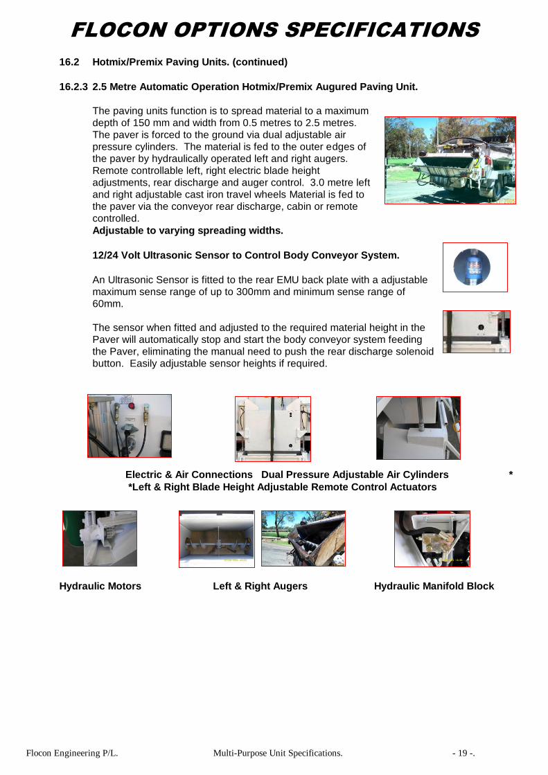
16.2.3 2.5 Metre Automatic Operation Hotmix/Premix Augured Paving Unit.
The paving units function is to spread material to a maximum
depth of 150 mm and width from 0.5 metres to 2.5 metres.
The paver is forced to the ground via dual adjustable air
pressure cylinders. The material is fed to the outer edges of
the paver by hydraulically operated left and right augers.
Remote controllable left, right electric blade height
adjustments, rear discharge and auger control. 3.0 metre left
and right adjustable cast iron travel wheels Material is fed to
the paver via the conveyor rear discharge, cabin or remote
controlled.
Adjustable to varying spreading widths.
12/24 Volt Ultrasonic Sensor to Control Body Conveyor System.
An Ultrasonic Sensor is fitted to the rear EMU back plate with a adjustable
maximum sense range of up to 300mm and minimum sense range of
60mm.
The sensor when fitted and adjusted to the required material height in the
Paver will automatically stop and start the body conveyor system feeding
the Paver, eliminating the manual need to push the rear discharge solenoid
button. Easily adjustable sensor heights if required.
Electric & Air Connections Dual Pressure Adjustable Air Cylinders *
*Left & Right Blade Height Adjustable Remote Control Actuators
Hydraulic Motors Left & Right Augers Hydraulic Manifold Block

Flocon Engineering P/L. Multi-Purpose Unit Specifications. - 20 -.
FLOCON OPTIONS SPECIFICATIONS
16.2 Hotmix/Premix Paving Units. (continued)
16.2.4 Hydraulic Winch.
Fitted with a hand manual control valve and hydraulic winch to raise and lower the paving unit.
The winch uses a 50mm loading strap for lowering and raising as well as a hold back valve,
to eliminate any creeping through the hydraulics.
The winch also has a hydraulic flow control valve to adjust the speed of the winch.
16.2.5 12/24 Volt Electric Winch.
Fitted with a 2041kg Super winch to raise and lower the unit.
Supplied with a hand held remote control.
Flocon Engineering P/L. Multi-Purpose Unit Specifications. - 21 -.
FLOCON OPTIONS SPECIFICATIONS
16 Spreading Equipment. (continued)
16.3 500 MM Off Road Edge Maintenance Units.
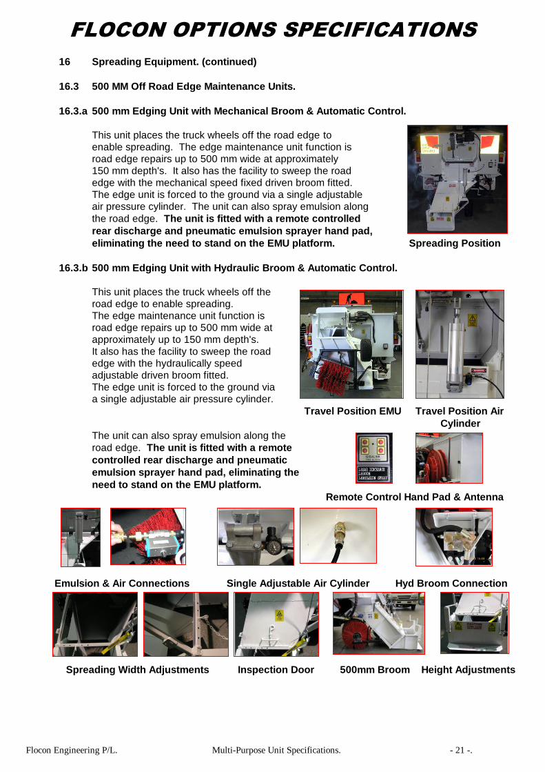
16.3.a 500 mm Edging Unit with Mechanical Broom & Automatic Control.
This unit places the truck wheels off the road edge to
enable spreading. The edge maintenance unit function is
road edge repairs up to 500 mm wide at approximately
150 mm depth's. It also has the facility to sweep the road
edge with the mechanical speed fixed driven broom fitted.
The edge unit is forced to the ground via a single adjustable
air pressure cylinder. The unit can also spray emulsion along
the road edge. The unit is fitted with a remote controlled
rear discharge and pneumatic emulsion sprayer hand pad,
eliminating the need to stand on the EMU platform. Spreading Position
16.3.b 500 mm Edging Unit with Hydraulic Broom & Automatic Control.
This unit places the truck wheels off the
road edge to enable spreading.
The edge maintenance unit function is
road edge repairs up to 500 mm wide at
approximately up to 150 mm depth's.
It also has the facility to sweep the road
edge with the hydraulically speed
adjustable driven broom fitted.
The edge unit is forced to the ground via
a single adjustable air pressure cylinder.
Travel Position EMU Travel Position Air
Cylinder
The unit can also spray emulsion along the
road edge. The unit is fitted with a remote
controlled rear discharge and pneumatic
emulsion sprayer hand pad, eliminating the
need to stand on the EMU platform.
Remote Control Hand Pad & Antenna
Emulsion & Air Connections Single Adjustable Air Cylinder Hyd Broom Connection
Spreading Width Adjustments Inspection Door 500mm Broom Height Adjustments
Flocon Engineering P/L. Multi-Purpose Unit Specifications. - 22 -.
FLOCON OPTIONS SPECIFICATIONS
16 Spreading Equipment. (continued)
16.3.c Hydraulic Winch.
Fitted with a hand manual control valve and hydraulic winch to raise
and lower the paving unit. The winch uses a 50mm loading strap for
lowering and raising as well as a hold back valve, to eliminate any
creeping through the hydraulics. The winch also has a hydraulic flow
control valve to adjust the speed of the winch.
16.3.d 12/24 Volt Electric Winch.
Fitted with a 2041kg Super winch to raise and lower the unit.
Supplied with a hand held remote control.
NOTE:
Only one winch either hydraulic or electric is required for the
Hotmix/Premix Paving Unit, Hotmix/Premix Off Road Edge Maintenance Unit.
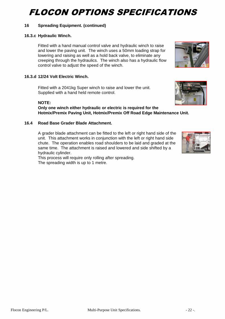
16.4 Road Base Grader Blade Attachment.
A grader blade attachment can be fitted to the left or right hand side of the
unit. This attachment works in conjunction with the left or right hand side
chute. The operation enables road shoulders to be laid and graded at the
same time. The attachment is raised and lowered and side shifted by a
hydraulic cylinder.
This process will require only rolling after spreading.
The spreading width is up to 1 metre.
Flocon Engineering P/L. Multi-Purpose Unit Specifications. - 23 -.
FLOCON OPTIONS SPECIFICATIONS
16 Spreading Equipment. (continued)
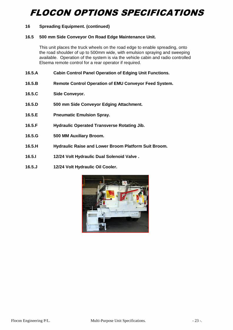
16.5 500 mm Side Conveyor On Road Edge Maintenance Unit.
This unit places the truck wheels on the road edge to enable spreading, onto
the road shoulder of up to 500mm wide, with emulsion spraying and sweeping
available. Operation of the system is via the vehicle cabin and radio controlled
Elsema remote control for a rear operator if required.
16.5.A Cabin Control Panel Operation of Edging Unit Functions.
16.5.B Remote Control Operation of EMU Conveyor Feed System.
16.5.C Side Conveyor.
16.5.D 500 mm Side Conveyor Edging Attachment.
16.5.E Pneumatic Emulsion Spray.
16.5.F Hydraulic Operated Transverse Rotating Jib.
16.5.G 500 MM Auxiliary Broom.
16.5.H Hydraulic Raise and Lower Broom Platform Suit Broom.
16.5.I 12/24 Volt Hydraulic Dual Solenoid Valve .
16.5.J 12/24 Volt Hydraulic Oil Cooler.
Flocon Engineering P/L. Multi-Purpose Unit Specifications. - 24 -.
FLOCON OPTIONS SPECIFICATIONS
16 Spreading Equipment. (continued)
16.5 500 mm Side Conveyor On Road Edge Maintenance Unit.
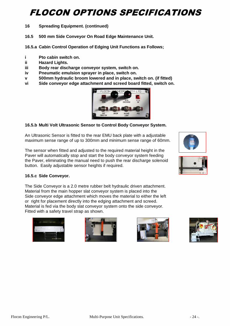
16.5.a Cabin Control Operation of Edging Unit Functions as Follows;
i Pto cabin switch on.
ii Hazard Lights.
iii Body rear discharge conveyor system, switch on.
iv Pneumatic emulsion sprayer in place, switch on.
v 500mm hydraulic broom lowered and in place, switch on. (if fitted)
vi Side conveyor edge attachment and screed board fitted, switch on.
16.5.b Multi Volt Ultrasonic Sensor to Control Body Conveyor System.
An Ultrasonic Sensor is fitted to the rear EMU back plate with a adjustable
maximum sense range of up to 300mm and minimum sense range of 60mm.
The sensor when fitted and adjusted to the required material height in the
Paver will automatically stop and start the body conveyor system feeding
the Paver, eliminating the manual need to push the rear discharge solenoid
button. Easily adjustable sensor heights if required.
16.5.c Side Conveyor.
The Side Conveyor is a 2.0 metre rubber belt hydraulic driven attachment.
Material from the main hopper slat conveyor system is placed into the
Side conveyor edge attachment which moves the material to either the left
or right for placement directly into the edging attachment and screed.
Material is fed via the body slat conveyor system onto the side conveyor.
Fitted with a safety travel strap as shown.
Flocon Engineering P/L. Multi-Purpose Unit Specifications. - 25 -.
FLOCON OPTIONS SPECIFICATIONS
16 Spreading Equipment. (continued)
16.5 500 mm Side Conveyor On Road Edge Maintenance Unit.
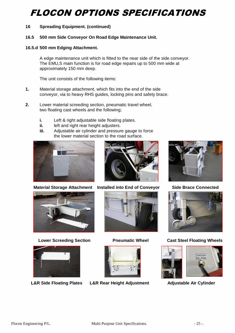
16.5.d 500 mm Edging Attachment.
A edge maintenance unit which is fitted to the near side of the side conveyor.
The EMU,S main function is for road edge repairs up to 500 mm wide at
approximately 150 mm deep.
The unit consists of the following items:
1. Material storage attachment, which fits into the end of the side
conveyor, via to heavy RHS guides, locking pins and safety brace.
2. Lower material screeding section, pneumatic travel wheel,
two floating cast wheels and the following;
i. Left & right adjustable side floating plates.
ii. left and right rear height adjusters.
iii. Adjustable air cylinder and pressure gauge to force
the lower material section to the road surface.
Material Storage Attachment Installed into End of Conveyor Side Brace Connected
Lower Screeding Section Pneumatic Wheel Cast Steel Floating Wheels
L&R Side Floating Plates L&R Rear Height Adjustment Adjustable Air Cylinder
Flocon Engineering P/L. Multi-Purpose Unit Specifications. - 26 -.
FLOCON OPTIONS SPECIFICATIONS
16 Spreading Equipment. (continued)
16.5 500 mm Side Conveyor On Road Edge Maintenance Unit.
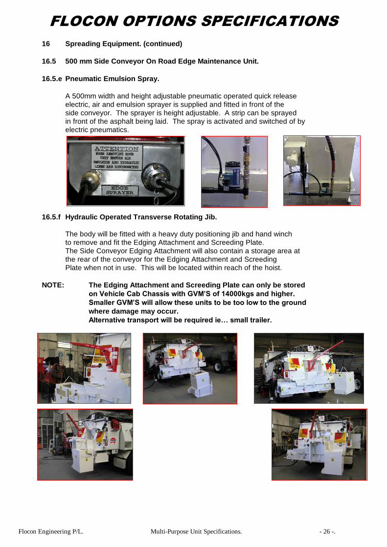
16.5.e Pneumatic Emulsion Spray.
A 500mm width and height adjustable pneumatic operated quick release
electric, air and emulsion sprayer is supplied and fitted in front of the
side conveyor. The sprayer is height adjustable. A strip can be sprayed
in front of the asphalt being laid. The spray is activated and switched of by
electric pneumatics.
16.5.f Hydraulic Operated Transverse Rotating Jib.
The body will be fitted with a heavy duty positioning jib and hand winch
to remove and fit the Edging Attachment and Screeding Plate.
The Side Conveyor Edging Attachment will also contain a storage area at
the rear of the conveyor for the Edging Attachment and Screeding
Plate when not in use. This will be located within reach of the hoist.
NOTE: The Edging Attachment and Screeding Plate can only be stored
on Vehicle Cab Chassis with GVM’S of 14000kgs and higher.
Smaller GVM’S will allow these units to be too low to the ground
where damage may occur.
Alternative transport will be required ie… small trailer.

Flocon Engineering P/L. Multi-Purpose Unit Specifications. - 27 -.
FLOCON OPTIONS SPECIFICATIONS
16 Spreading Equipment. (continued)
16.5 500 mm Side Conveyor On Road Edge Maintenance Unit.
16.5.g 500 MM Auxiliary Broom.
A auxiliary broom which is fitted to the near side of the vehicle
in front of the edge maintenance unit. The broom is fitted
with a dust cover. Mounting is in on hydraulic platform,
with variable height adjustments and variable broom speed
control. If Room permits for fitting on the vehicle only.
1
16.5.h Hydraulic Raise and Lower Broom Platform.
The hydraulic equipment control moves the broom to the
sweeping position required and also to the correct height for transport. Mechanical locks are
provided in the transport position. The platform is the same as for the compaction equipment
and is fitted with a hold back valve
to eliminate the platform creeping when placed into the desired sweeping position.
16.5.i 12/24 Volt Hydraulic Dual Solenoid Valve.
The supply of a secondary hydraulic flow control valve is required to
operate the side conveyor simultaneously with the body rear discharge
conveyor system. Including wiring Into the vehicle cabin.
The valve has the facility to also accept the hydraulic auxiliary broom
system if required.
Flocon Engineering P/L. Multi-Purpose Unit Specifications. - 28 -.
FLOCON OPTIONS SPECIFICATIONS
16 Spreading Equipment. (continued)
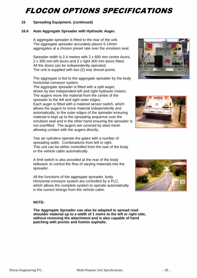
16.6 Auto Aggregate Spreader with Hydraulic Auger.
A aggregate spreader is fitted to the rear of the unit.
The aggregate spreader accurately places 5-14mm
aggregates at a chosen preset rate over the emulsion seal.
Spreader width is 2.4 metres with 2 x 600 mm centre doors,
2 x 300 mm left doors and 2 x right 300 mm doors fitted.
All the doors can be independently operated.
The unit is supplied with two (2) rear shovel points.
The aggregate is fed to the aggregate spreader by the body
horizontal conveyor system.
The aggregate spreader is fitted with a split auger,
driven by two independent left and right hydraulic motors.
The augers move the material from the centre of the
spreader to the left and right outer edges.
Each auger is fitted with a material sensor switch, which
allows the augers to move material independently and
automatically, to the outer edges of the spreader ensuring
material is kept up to the spreading sequence over the
emulsion seal and in the other hand ensuring the spreader is
not overfilled. The augers are covered by steel mesh
allowing contact with the augers directly.
Two air cylinders operate the gates with a number of
spreading width. Combinations from left to right.
This unit can be either controlled from the rear of the body
or the vehicle cabin automatically.
A limit switch is also provided at the rear of the body
tailboard, to control the flow of varying materials into the
spreader.
All the functions of the aggregate spreader, body
Horizontal conveyor system are controlled by a PLC,
which allows the complete system to operate automatically
in the correct timings from the vehicle cabin.
NOTE: The Aggregate Spreader can also be adapted to spread road shoulder material up to a width of 1 metre to the left or right side, without removing the attachment and is also capable of hand patching with premix and hotmix asphalts.

Flocon Engineering P/L. Multi-Purpose Unit Specifications. - 29 -.
FLOCON OPTIONS SPECIFICATIONS
16 Spreading Equipment. (continued)
16.6 Auto Aggregate Spreader with Hydraulic Auger. (continued)
Rear Shovel Point Closed & Open Auger & Protective Mesh Auger Sensor Switch
Rear Control Panel Operation & Switches Tailboard Limit Switch PLC Programmer
16.6.a Hydraulic Winch.
Fitted with a hand manual control valve and hydraulic winch
to raise and lower the unit onto free standing frames.
The winch uses a 50mm loading strap for lowering and
raising as well as a hold back valve, to eliminate any
creeping through the hydraulics.
The winch also has a hydraulic flow control valve to adjust
the speed of the winch.
the speed of the winch.
16.6.b Air Tailgate.
The unit is fitted with an air cylinder to open and close the
tailgate at the rear of the body.
16.7 Grit/Salt/Soil Spinner.
The grit spreader spinner places grit, sand, soil and fertiliser in
various applications. The speed of the body main conveyor chain and
spinner are variable to allow different spread rates.
The operation of the spinner can be from the rear of the body or from the
Cab-chassis cabin. Spread width up to 8 metres wide.

Flocon Engineering P/L. Multi-Purpose Unit Specifications. - 30 -.
FLOCON OPTIONS SPECIFICATIONS
16 Spreading Equipment. (continued)
16.8 Drainage Back Filling Hydraulic Side Conveyors.
16.8.a Drainage Back Filling Hydraulic Side Conveyor.
A 2.0 metre Side Conveyor Attachment to suit 4x2 single axle
Vehicles only. The conveyor is a rubber belt hydraulic driven
attachment with a 1.0 metre reach outside the vehicle wheel line.
Material from the main hopper conveyor system is placed into the
Side Conveyor which moves the material to either the left or right
for placement directly onto the ground. The unit is used for trench
bedding, back filling, road shoulders, kerb and channel bedding,
soil and rock placement on batters, asphalt strip laying and filling
sand bags etc. An installation trolley is included.
16.8.b Drainage Back Filling Hydraulic Side Conveyor.
A 2.5 metre Side Conveyor Attachment to suit 6-8x4 single axle
vehicles only. The conveyor is a rubber belt hydraulic driven
attachment with a 1.5 metre reach outside the vehicle wheel
line. Material from the main hopper conveyor system is placed
into the Side Conveyor which moves the material to either the left
or right for placement directly onto the ground. The unit is used
for trench bedding, back filling, road shoulders, kerb and channel
bedding, soil and rock placement on batters, asphalt strip laying
and filling sand bags etc. An installation trolley is included.
16.8.c Cabin Controlled Variable Side Conveyor Speed.
Cabin controlled adjustable and variable belt speed of the conveyor.
16.8.d Hydraulic Side Shift One Way to Suit the Side Conveyor.
A hydraulic cylinder is fitted to move the conveyor 1 metre one way for
spreading, vehicle cabin controlled.
16.8.e Hydraulic Side Shift Left or Right to Suit the Side Conveyor.
A hydraulic cylinder is fitted to move the conveyor left or right by 1 metre
for spreading, vehicle cabin controlled.

Flocon Engineering P/L. Multi-Purpose Unit Specifications. - 31 -.
STANLEY HYDRAULIC SPECIFICATIONS
STANLEY HAND HELD HYDRAULIC BREAKERS SPECIFICATIONS:
1 Light Asphalt Breaker Stanley Model DR19111.
Hex Size 7/8”. Weight 10.9 kgs.
________________________________________________________________________________
2 Light Asphalt Breaker Stanley Model BR37110.
Hex size 7/8”. Weight 17 kgs.
Easy Ride Foot Facility not Available.
‘T’ Handle.
______________________________________________________________________________________
3 Medium Asphalt Breaker Stanley Model BR40550.
Hex size 1”. Weight 18 kgs.
Easy Ride Foot Facility not Available.
‘T’ Handle.
______________________________________________________________________________________
4 Medium Asphalt Breaker Stanley Model BR45120E.
Hex size 1 1/8”. Weight 22 kgs.
Easy Ride Foot Facility.
______________________________________________________________________________________
5 Medium Asphalt Breaker Stanley Model BR45130E.
Hex size 1 1/4”. Weight 22 kgs.
Easy Ride Foot Facility.
______________________________________________________________________________________
6 Medium Asphalt Breaker Stanley Model BR45125S.
Hex size 1 1/8”. Weight 26kgs.
Easy Ride Foot Facility.
Spring Handle Anti Vibration.
______________________________________________________________________________________
7 Medium Asphalt Breaker Stanley Model BR45135S.
Hex size 1 1/4”. Weight 22 kgs.
Easy Ride Foot Facility.
Spring Handle Anti Vibration.
______________________________________________________________________________________
8 Medium - Heavy Asphalt Breaker Stanley Model BR67120E.
Hex size 1 1/8”. Weight 30 kgs.
Easy Ride Foot Facility.
______________________________________________________________________________________
9 Medium-Heavy Asphalt Breaker Stanley Model BR67130E.
Hex size 1 1/4”. Weight 30 kgs.
Easy Ride Foot Facility.
______________________________________________________________________________________
10 Medium - Heavy Asphalt Breaker Stanley Model BR72120.
Hex size 1 1/8”. Weight 27 kgs.
Easy Ride Foot Facility.
‘T’ Handle.
______________________________________________________________________________________
11 Medium-Heavy Asphalt Breaker Stanley Model BR72130.
Hex size 1 1/4”. Weight 27 kgs.
Easy Ride Foot Facility not Available.
‘T’ Handle.
Flocon Engineering P/L. Multi-Purpose Unit Specifications. - 32 -.
STANLEY HYDRAULIC SPECIFICATIONS
STANLEY HAND HELD HYDRAULIC BREAKERS SPECIFICATIONS:
12 Medium - Heavy Asphalt Breaker Stanley Model BR72125S.
Hex size 1 1/8”. Weight 27.6 kgs.
Easy Ride Foot Facility.
Spring Handle Anti Vibration.
______________________________________________________________________________________
13 Medium-Heavy Asphalt Breaker Stanley Model BR72135S.
Hex size 1 1/4”. Weight 27.6 kgs.
Easy Ride Foot Facility.
Spring Handle Anti Vibration.
______________________________________________________________________________________
14 Heavy Asphalt Breaker Stanley Model BR87120.
Hex size 1 1/8”. Weight 37.7 kgs.
Easy Ride Foot Facility not Available.
‘T’ Handle.
______________________________________________________________________________________
15 Heavy Asphalt Breaker Stanley Model BR87130.
Hex size 1 1/4”. Weight 37.7 kgs.
Easy Ride Foot Facility not Available.
‘T’ Handle.
______________________________________________________________________________________
16 Heavy Asphalt Breaker Stanley Model BR89120.
Hex size 1 1/8”. Weight 37.7 kgs.
Easy Ride Foot Facility not Available.
‘T’ Handle.
______________________________________________________________________________________
17 Heavy Asphalt Breaker Stanley Model BR89130.
Hex size 1 1/4”. Weight 37.7 kgs.
Easy Ride Foot Facility not Available.
‘T’ Handle.

Flocon Engineering P/L. Multi-Purpose Unit Specifications. - 33 -.
STANLEY HYDRAULIC SPECIFICATIONS
STANLEY HAND HELD HYDRAULIC BREAKERS TOOLS SPECIFICATIONS:
1 7/8” HEX BREAKER TOOLS:
1.1 7/8” Hex, Moil Point.
1.2 7/8” Hex, 1” Chisel.
1.3 7/8” Hex, Asphalt Cutter.
1.4 7/8” Hex, Clay Spade.
______________________________________________________________________________________
2 1” HEX BREAKER TOOLS:
2.1 1” Hex, Moil Point.
2.2 1” Hex, 1” Chisel.
2.3 1” Hex, Asphalt Cutter.
2.4 1” Hex, Clay Spade.
______________________________________________________________________________________
3 1 1/8” HEX BREAKER TOOLS:
3.1 1 1/8” Hex, Moil Point.
3.2 1 1/8” Hex, 1” Chisel.
3.3 1 1/8” Hex, Asphalt Cutter.
3.4 1 1/8” Hex, Clay Spade.
3.5 1 1/8” Hex, Tamper Stem Suit 5” Pad.
3.6 1 1/8” Hex, Tamper 5” Pad.
______________________________________________________________________________________
4 1 1/4” HEX BREAKER TOOLS:
4.1 1 1/4” Hex, Moil Point.
4.2 1 1/4” Hex, 1” Chisel.
4.3 1 1/4” Hex, Asphalt Cutter.
4.4 1 1/4” Hex, Clay Spade.
4.5 1 1/4” Hex, Tamper Stem Suit 5” or 7”Pad.
4.6 1 1/4” Hex, Tamper 5” or 7” Pad.
Flocon Engineering P/L. Multi-Purpose Unit Specifications. - 34 -.
STANLEY HYDRAULIC SPECIFICATIONS
STANLEY HAND HELD HYDRAULIC OTHER TOOLS SPECIFICATIONS:
1 CS23821 Long reach pole saw. 12' saw bar.
______________________________________________________________________________________
2 TA54103 hydraulic tamper with 150 mm round foot.
______________________________________________________________________________________
3 TA57112 hydraulic tamper with 150 mm round foot.
______________________________________________________________________________________
4 CO25541 hydraulic cut-off saw takes 14” blade.
______________________________________________________________________________________
5 Diamond Blade 14” asphalt/concrete cutting suit CO23541.
______________________________________________________________________________________
6 Walk behind cart to suit CO23541.
______________________________________________________________________________________
7 Stanley Hex Post Borer Equipment.
7.1 EO8102A, 1 3/8” Hex Two Man Handle Attachment.
Including 47415, 15” extension tube.
Hydraulic post hole borer with one man handle and unique kickback free
operation attaching to a bracket on the side of the Flocon unit.
Standard Tip Augers:
42” Length Auger:
7.2 39413 50mm tow ball connection.
7.3 47406 2” diameter auger.
7.4 47407 3” diameter auger.
7.5 47408 4” diameter auger.
7.6 47409 6” diameter auger.
7.7 47410 8” diameter auger.
7.8 47411 10” diameter auger.
7.9 47412 12” diameter auger.
7.10 47413 14” diameter auger.
7.11 47414 16” diameter auger.
7.12 47429 Digging tooth w/hard face.
Flocon Engineering P/L. Multi-Purpose Unit Specifications. - 35 -.
CONSTRUCTION EQUIPMENT SPECIFICATIONS
1 Wacker Construction Equipment.
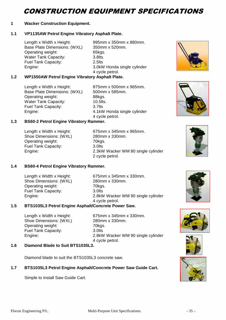
1.1 VP1135AW Petrol Engine Vibratory Asphalt Plate.
Length x Width x Height: 995mm x 350mm x 880mm.
Base Plate Dimensions: (WXL) 350mm x 520mm.
Operating weight: 65kgs.
Water Tank Capacity: 3.8lts.
Fuel Tank Capacity: 2.5lts
Engine: 3.0kW Honda single cylinder
4 cycle petrol.
1.2 WP1550AW Petrol Engine Vibratory Asphalt Plate.
Length x Width x Height: 875mm x 500mm x 965mm.
Base Plate Dimensions: (WXL) 500mm x 585mm.
Operating weight: 88kgs.
Water Tank Capacity: 10.5lts.
Fuel Tank Capacity: 3.7lts
Engine: 4.1kW Honda single cylinder
4 cycle petrol.
1.3 BS60-2 Petrol Engine Vibratory Rammer.
Length x Width x Height: 675mm x 345mm x 965mm.
Shoe Dimensions: (WXL) 280mm x 330mm.
Operating weight: 70kgs.
Fuel Tank Capacity: 3.0lts
Engine: 2.3kW Wacker WM 80 single cylinder
2 cycle petrol.
1.4 BS60-4 Petrol Engine Vibratory Rammer.
Length x Width x Height: 675mm x 345mm x 330mm.
Shoe Dimensions: (WXL) 280mm x 330mm.
Operating weight: 70kgs.
Fuel Tank Capacity: 3.0lts
Engine: 2.8kW Wacker WM 90 single cylinder
4 cycle petrol.
1.5 BTS1035L3 Petrol Engine Asphalt/Concrete Power Saw.
Length x Width x Height: 675mm x 345mm x 330mm.
Shoe Dimensions: (WXL) 280mm x 330mm.
Operating weight: 70kgs.
Fuel Tank Capacity: 3.0lts
Engine: 2.8kW Wacker WM 90 single cylinder
4 cycle petrol.
1.6 Diamond Blade to Suit BTS1035L3.
Diamond blade to suit the BTS1035L3 concrete saw.
1.7 BTS1035L3 Petrol Engine Asphalt/Concrete Power Saw Guide Cart.
Simple to install Saw Guide Cart.

Flocon Engineering P/L. Multi-Purpose Unit Specifications. - 36 -.
CONSTRUCTION EQUIPMENT SPECIFICATIONS
1 Wacker Construction Equipment. (Continued)
1.8 BH23 Petrol Engine Asphalt/Concrete Breaker.
Tool Hex Size: 1 1/8”.
Length x Width x Height: 790mm x 450mm x 333mm.
Operating weight: 23kgs.
Fuel Tank Capacity: 1.8lts
Engine: 2.0 kW Wacker WM 80 single cylinder
2 cycle petrol.
2 Bomag Roller Construction Equipment.
2.1 Bomag BE55E Single Drum Pedestrian Roller.
Width: 560mm.
Weight: 161kgs.
Frequency: 77Hz.
Engine: Honda single cylinder
4 cycle petrol.