Multi Protocol Label Switching (QoS & Traffic...
32
Andrea Detti, Univ. Roma Tor Vergata, Ingegneria di Internet Andrea Detti, Univ. Roma Tor Vergata, Ingegneria di Internet Slide 1 Multi Protocol Label Switching (QoS & Traffic Enginnering)
Transcript of Multi Protocol Label Switching (QoS & Traffic...

Andrea Detti, Univ. Roma Tor Vergata, Ingegneria di InternetAndrea Detti, Univ. Roma Tor Vergata, Ingegneria di Internet Slide 1
Multi Protocol Label Switching(QoS & Traffic Enginnering)
Andrea Detti, Univ. Roma Tor Vergata, Ingegneria di InternetSlide 2
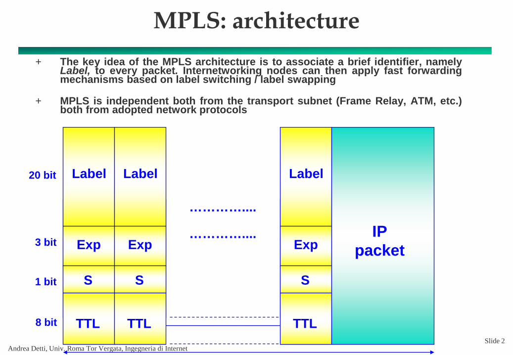
MPLS: architecture+ The key idea of the MPLS architecture is to associate a brief identifier, namely
Label, to every packet. Internetworking nodes can then apply fast forwardingmechanisms based on label switching / label swapping
+ MPLS is independent both from the transport subnet (Frame Relay, ATM, etc.)both from adopted network protocols
Label
Exp
S
TTL
Label
Exp
S
TTL
Label
Exp
S
TTL
PacchettoIP
…………....
20 bit
3 bit
8 bit
1 bit
Label
Exp
S
TTL
Label
Exp
S
TTL
Label
Exp
S
TTL
IPpacket
…………....

Andrea Detti, Univ. Roma Tor Vergata, Ingegneria di InternetSlide 3
MPLS networknode Forwarding component (L2 switch)
Control component (router + LDP)
Label Switch= +
MPLS node
+ Control Component• A set of modules dealing with Label allocation and binding Labels between adjacent
nodes• Layer 3 «intelligence» (IP addressing, IP routing)
+ Forwarding Component• Forwarding based on the label swapping paradigm
+ The two components must be independent: they can employ differentprotocols within every medium
+ The Control Component is sometimes realized as a part (SW or HW) ofthe network node, other times as external controller
Andrea Detti, Univ. Roma Tor Vergata, Ingegneria di InternetSlide 4
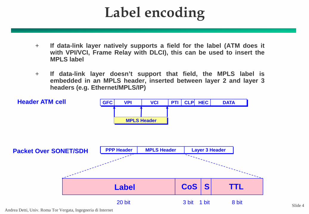
Label encoding
Packet Over SONET/SDH
Header ATM cell
MPLS HeaderPPP Header Layer 3 Header
HEC
MPLS Header
DATACLPPTIVCIGFC VPI
+ If data-link layer natively supports a field for the label (ATM does itwith VPI/VCI, Frame Relay with DLCI), this can be used to insert theMPLS label
+ If data-link layer doesn’t support that field, the MPLS label isembedded in an MPLS header, inserted between layer 2 and layer 3headers (e.g. Ethernet/MPLS/IP)
Label CoS S TTL
20 bit 3 bit 8 bit1 bit

Andrea Detti, Univ. Roma Tor Vergata, Ingegneria di InternetSlide 5
Terminology
+ Label Edge Router (LER): edge routers for an MPLS network: they haveforwarding functionalities from and to the outer networks, applying andremoving the labels to ingress and egress packets
+ Label Switching Router (LSR): switches operating label swapping inside theMPLS network and supporting forwarding functionalities
+ Label Distribution Protocol (LDP): in conjunction with traditional routingprotocols, LDP is used for distributing labels between network devices
+ Forwarding Equivalence Class (FEC): a set of IP packets that are forwarded inthe same way (for instance along the same path, with the same treatment)
+ Label Switched Path (LSP): the path through one or more LSRs followed by apacket belonging to a certain FEC

Andrea Detti, Univ. Roma Tor Vergata, Ingegneria di InternetSlide 6
Operation
+ The ingress LER of the MPLS backbone analyzes thepacket’s IP header, classifies the packet, adds thelabel and forwards it to the next hop LSR
+ In the LSRs cloud the packet is forwarded along theLSP according to the label
+ The egress LER removes the label and the packet isforwarded based on IP destination address

Andrea Detti, Univ. Roma Tor Vergata, Ingegneria di InternetSlide 7
Label Switching Operation: Control
+ LDP is used for distributing the <label, prefix> associations betweenMPLS nodes
LDP creates the associationsbetween routes and labels that are stored in a table named LIB (Label Information Base)
LER
LER
LERLER
LER
LSR
LSR
LSR
LSR
LSRLSR

Andrea Detti, Univ. Roma Tor Vergata, Ingegneria di InternetSlide 8
LDP: Downstream on Demand
i/f 1
i/f 0
i/f 1
i/f 0
i/f 0
128.89.10.0
171.69.0.0
128.89.10.0 0
171.69.0.0 1
addr. prefix i/fremotelabel
locallabel
128.89.10.0 0
addr. prefix i/fremote
labellocallabel
x
171.69.0.0 0
addr. prefix i/fremotelabel
locallabel
x
128.89.10.0 1
171.69.0.0 1
addr. prefix i/fremote
labellocallabel
x
x
Data Flow
Label Request<128.89.10.0><171.69.0.0>
LER
LER
LER
LSR

Andrea Detti, Univ. Roma Tor Vergata, Ingegneria di InternetSlide 9
i/f 1
i/f 0
i/f 1
i/f 0
i/f 0
128.89.10.0
171.69.0.0
128.89.10.0 0
171.69.0.0 1
addr. prefix i/f
128.89.10.0 0
addr. prefix i/f
x
171.69.0.0 0
addr. prefix i/f
x
128.89.10.0 1
171.69.0.0 1
addr. prefix i/fx
x
Data Flow
Label Mapping<3,128.89.10.0><4,171.69.0.0>
4
34
3
remotelabel
locallabel
remotelabel
locallabel
remotelabel
locallabel
remotelabel
locallabel
LER
LER
LER
LSR
LDP: Downstream on Demand
Andrea Detti, Univ. Roma Tor Vergata, Ingegneria di InternetSlide 10
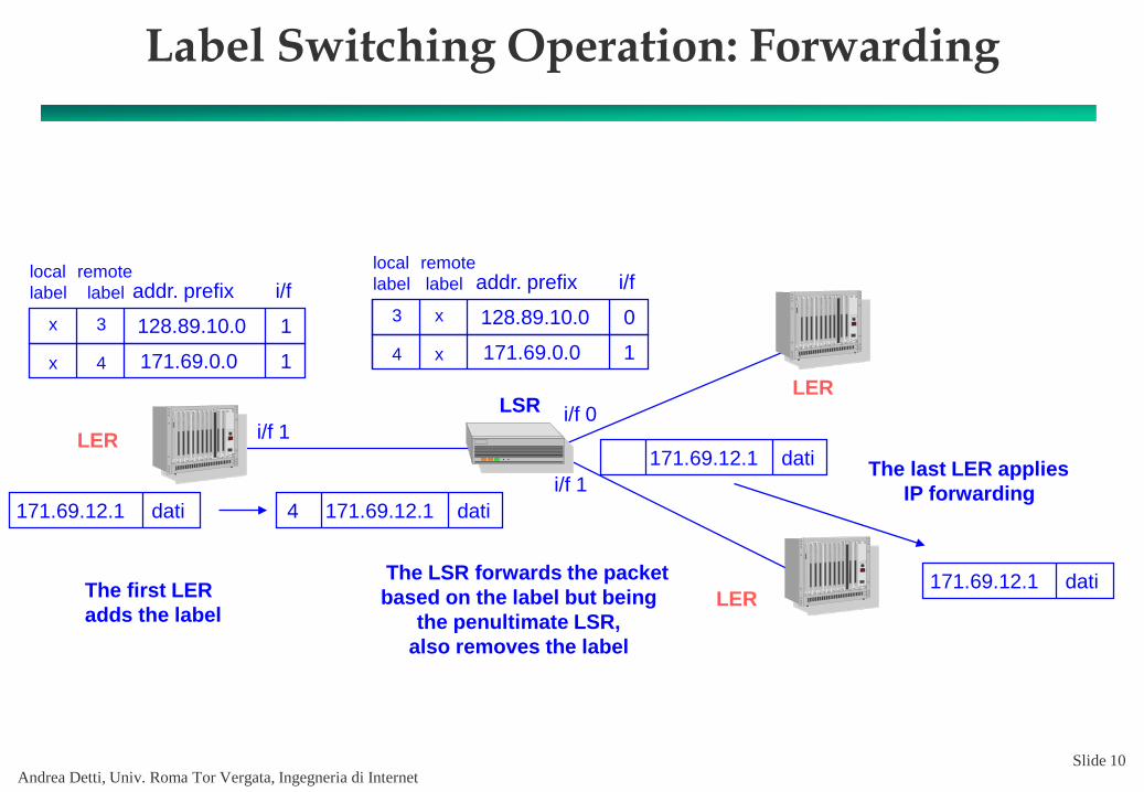
Label Switching Operation: Forwarding
i/f 1i/f 0
i/f 1
128.89.10.0 0
171.69.0.0 1
addr. prefix i/f
128.89.10.0 1
171.69.0.0 1
addr. prefix i/fx
x 4
34
3
x
x
171.69.12.1 dati 171.69.12.1 dati4
171.69.12.1 dati
171.69.12.1 datiThe first LER adds the label
The LSR forwards the packet based on the label but being
the penultimate LSR, also removes the label
The last LER appliesIP forwarding
remotelabel
locallabel
remotelabel
locallabel
LER
LER
LER
LSR

Andrea Detti, Univ. Roma Tor Vergata, Ingegneria di InternetSlide 11
LDP: Downstream Unsolicited vs OnDemand
OnDemand Unsolicited(Cisco default)

Andrea Detti, Univ. Roma Tor Vergata, Ingegneria di InternetSlide 12
Label Stacking
+ MPLS label can be stacked to aggregate, in a network section, two or more LSPin a single LSP with higher pecking order
+ Label insertion is named after label push
+ Label removal is names after label pop
+ Forwarding is always made according to the highest order label; if there isn’t alabel, IP level forwarding is applied
IPL=x
IPL=y
LSRIPL=x
L=z
L=z
IPL=yPUSH label z
IPL=x
IPL=yPOP label

Andrea Detti, Univ. Roma Tor Vergata, Ingegneria di InternetSlide 13
MPLS: reality
+ Why do ISPs employ MPLS?• The key advantage is that MPLS enables an ISP the offering of
new services that cannot be supported simply throughconventional routing technology
+ By now, there are three main MPLS use cases in ISPcores
• Traffic Engineering (MPLS-TE)• Traffic Engineering with QoS (MPLS DS-TE)• Virtual Private Networks (VPN)
Andrea Detti, Univ. Roma Tor Vergata, Ingegneria di InternetSlide 14
MPLS-TE
+ Traffic Engineering enables the forwarding of acertain traffic flow along a path possibly differentfrom the one calculated by the routing protocol. Inthis way it can use a less congested path (ifnecessary)
+ This allows to ISPs the load balancing on the variouslinks and network nodes so that none of them isunder or over utilized
+ MPLS-TE extends the base MPLS functionalitiesincluding:
• Mechanisms for network monitoring of link utilization• Mechanism for RSVP-TE/CR-LSP signalling to setup LSPs with
forced routing

Andrea Detti, Univ. Roma Tor Vergata, Ingegneria di InternetSlide 15
Traffic Engineering: how?
+ Normally, an LSP is setup according to the computationmade by the backbone routing protocol of the path withthe lower cost
+ Questa modalità non offre nessun valore aggiunto intermini di traffic engineering
+ This mode doesn’t offer anything in terms of TrafficEngineering
+ For the different setup of an LSP with respect to the onedetermined by the routing protocol, various mechanismscan be used:
• Static configuration of all LRS in the LSP (in the same way an IP/ATMtranditional backbone is configured)
• LER configuration with the whole path. Then the LER uses a modifiedversion of RSVP protocol to install the LIBs for each LSR along the path(LSP)

Andrea Detti, Univ. Roma Tor Vergata, Ingegneria di InternetSlide 16
Routing of an LSP
+ The path an LSP has to follow in order to cross the links withappropriate capacity is usually pre-computed by an offline tool
+ Knowing the output interfaces utilization of LERs is mandatory:• A) Proprietary solutions exploiting queries to LSR’s MIB• B) Extension of link-state routing protocols (flooding of interfaces’
information), ICP like OSPF or IS-IS, in a way that they are bringing alsoutilization state of resources. Then LERs (or a centralized management entity) can know about both topology and network utilization
+ Path calculation through Constraint-based, Shortest Path First(CSPF)
• Shortest path algorithm calculated upon the network topology except forthe links that can’t support the bandwidth of the LSP on which the setup isbeing made
+ Manual setup or with RSVP-TE / CR-LDP

Andrea Detti, Univ. Roma Tor Vergata, Ingegneria di InternetSlide 17
LSP: static configuration
R1 R2
LSR1
R3 R4
LSR2LSR3
45 Mbps 1.5 Mbps
45 Mbps
Static configurationR2R4 needs 1 MbpsR1R3 needs 2 MbpsR1R4 needs 2 Mbps

Andrea Detti, Univ. Roma Tor Vergata, Ingegneria di InternetSlide 18
LSP: configuration with RSVP-TE
Setup: Path (R1->R2->R6->R7->R4->R9)
Reply: RESV (Notify the labels)
Pop
22
4917
R8
R2
R6
R3R4
R7
R1 R5
R9
32

Andrea Detti, Univ. Roma Tor Vergata, Ingegneria di InternetSlide 19
RSVP-TE

Andrea Detti, Univ. Roma Tor Vergata, Ingegneria di InternetSlide 20
LSP: configuration with CR-LDP
Setup: Label Request (R1->R2->R6->R7->R4->R9)
Reply: Label mapping
22
4917
R8
R2
R6
R3R4
R7
R1 R5
R9
32

Andrea Detti, Univ. Roma Tor Vergata, Ingegneria di InternetSlide 21
MPLS & QoS
+ The Engineering of traffic implies a planning of the resources usage inorder to permit an effective transfer of data across the LSPs
+ So traffic engineering tries to make links minimally loaded
+ How do we handle different service classes?
+ Rule of thumb: In the case the overall requested capacity from all LSPson an output interface of an LSR is less or equal to half of the linkcapacity, all LSPs will experience a low delay, so schedulingmechanisms (e.g. WDRR) aren’t required
+ When, in post traffic engineering, the interfaces capacity start to workwith loads >> 0.5, a differenciation on how the traffic is handled isnecessary
+ MPLS can cooperate with DiffServ

Andrea Detti, Univ. Roma Tor Vergata, Ingegneria di InternetSlide 22
MPLS and DiffServ
+ What is the classification criteryon an LSR adopts to determine thescheduler queue occupation (i.e. the DiffServ forwarding-behavior)?
+ Two solutions:• Exp inferred LSP (E-LSP)
– Scheduler classification is made through Exp (3 bit) field of the MPLS header– Forwarding behavior and drop precedence inferred by the Exp field codification– Pachetti di LSP diversi con lo stesso campo Exp sono trattati ugualmente– Different LSP packets with the same Exp field are treated equally– Requires a maximum of 8 scheduler queues, the number of the possible values of the
Exp field
• Label inferred LSP (L-LSP)– Forwarding behavior is label inferred, drop precedence is Exp inferred– Each LSP can be handled with a different forwarding behavior regardless of Exp field– Requires a variable number of scheduler queues– More complex but more versatile– The <forwarding-behavior, label> association must be explicitally signalled during the
LSP setup

Andrea Detti, Univ. Roma Tor Vergata, Ingegneria di Internet
MPLS & BGP
+ BGP is the routing protocol used between ASs
+ BGP is executed byAS border gateways
+ BGP tables containall the routes to theInternet
• 2018 almost 800k routes(http://bgp.potaroo.net/)
Slide 23

Andrea Detti, Univ. Roma Tor Vergata, Ingegneria di Internet
MPLS & BGP
Slide 24
+ Problem: how can internal routers (e.g. R2) forward transitpackets, i.e. intended to one of the 800k external routes?
• Replicate BGP tables also in core routers (costly)• Full mesh LSPs between border routers through which only transit traffic is
forwarded– Internal routers only matters about routing tables to reach internal network
nodes
R3
R2
R1
BGP(1) Net a.a.a.a…..…..(400 k) Net z.z.z.z
Large BGP Table
(1) Net a.a.a.a…..…..(400 k) Net z.z.z.z
Large BGP TableBGP
Autonomous system
IGP
(1) Net 1.1.1.1
Small IGP Table
MPLS LSP

Andrea Detti, Univ. Roma Tor Vergata, Ingegneria di InternetAndrea Detti, Univ. Roma Tor Vergata, Ingegneria di Internet
Cisco MPLS tools
Slide 25

Andrea Detti, Univ. Roma Tor Vergata, Ingegneria di Internet
MPLS/LDP basic
+ Setup a MPLS LSP for each network prefix followingthe IP OSPF routes
+ Configure IGP (e.g. OSPF)
+ Configure label range• R2(config)# mpls label range 32 200 static 16 31
+ Enable MPLS general engine• R2(config)#mpls ip
+ Enable MPLS on single interface• R2(config-if)#mpls ip
+ Now LDP is active by default and …Slide 26

Andrea Detti, Univ. Roma Tor Vergata, Ingegneria di Internet
MPLS/LDP basic
+ LDP default behavior is unsolicited downstream mode+ Allocate and announce to downstream LSRs a local
label for• all non-BGP prefixes, which includes IGP learned prefixes and
connected interfaces with LDP on
+ The downstream LSR inserts in its MPLS forwardingtable only FEC/LABEL mappings coming from theNext-hop IP LSR for the related FEC
+ Debug commands• R2#show mpls forwarding-table• R2#show mpls ldp bindings
– All association FEC label• show mpls ldp neighbor
Slide 27

Andrea Detti, Univ. Roma Tor Vergata, Ingegneria di Internet
MPLS Traffic Engineering with tunnels
+ Global conf• ip cef [distributed] (default)• mpls traffic-eng tunnels
+ Link bandwidth information distribution• router ospf 1
– mpls traffic-eng router-id loopback0– mpls traffic-eng area ospf-area
+ On each physical interface• interface f0/0• mpls traffic-eng tunnels• ip rsvp bandwidth kbps subpool kbps
Slide 28

Andrea Detti, Univ. Roma Tor Vergata, Ingegneria di Internet
MPLS Traffic Engineering with tunnels
+ Build the tunnel• interface Tunnel0
– ip unnumbered loopback0– tunnel destination RID-of-tail
– tunnel mode mpls traffic-eng
+ Tunnel attributes• interface Tunnel0
– tunnel mpls traffic-eng bandwidth [sub-pool] Kbps• tunnel mpls traffic-eng bandwidth 1000
– tunnel mpls traffic-eng priority pri [hold-pri] pri [setup-priority]• tunnel mpls traffic-eng priority 7 7• Lower is better• Hold>=Setup to avoid instability
– tunnel mpls traffic-eng exp value• tunnel mpls traffic-eng exp 5
Slide 29
subpool
Global pool
RSVP bandwidth pools (Russian Dolls)

Andrea Detti, Univ. Roma Tor Vergata, Ingegneria di Internet
MPLS Traffic Engineering with tunnels
+ Dynamic path calculation• int Tunnel0
– tunnel mpls traffic-eng path-option dynamic
+ Explicit path calculation• int Tunnel0
– tunnel mpls traffic path-opt explicit name foo• ip explicit-path name foo
– next-address 1.2.3.4 [loose]– next-address 1.2.3.8 [loose]
Slide 30

Andrea Detti, Univ. Roma Tor Vergata, Ingegneria di Internet
MPLS Traffic Engineering with tunnels
+ Static routing to inject traffic on tunnel• ip route prefix mask Tunnel0
+ Policy Routing• access-list 101 permit ip any any dscp 20• access-list 102 permit ip any any dscp 0• interface Serial0
– ip policy route-map foo• route-map foo permit 10
– match ip address 101– set interface Tunnel0
• route-map foo permit 20– match ip address 102– set interface Tunnel1
• Be careful: MUST be possible to route the packet via the plain routing-table, also if a destination is forced withroute-map
– in case routes for tunnels was not present, the routing-table can use a static route: ip route 0.0.0.0 0.0.0.0 null 0
+ Debug• show mpls traffic-eng topology• show mpls traffic-eng tunnels
Slide 31
Andrea Detti, Univ. Roma Tor Vergata, Ingegneria di Internet
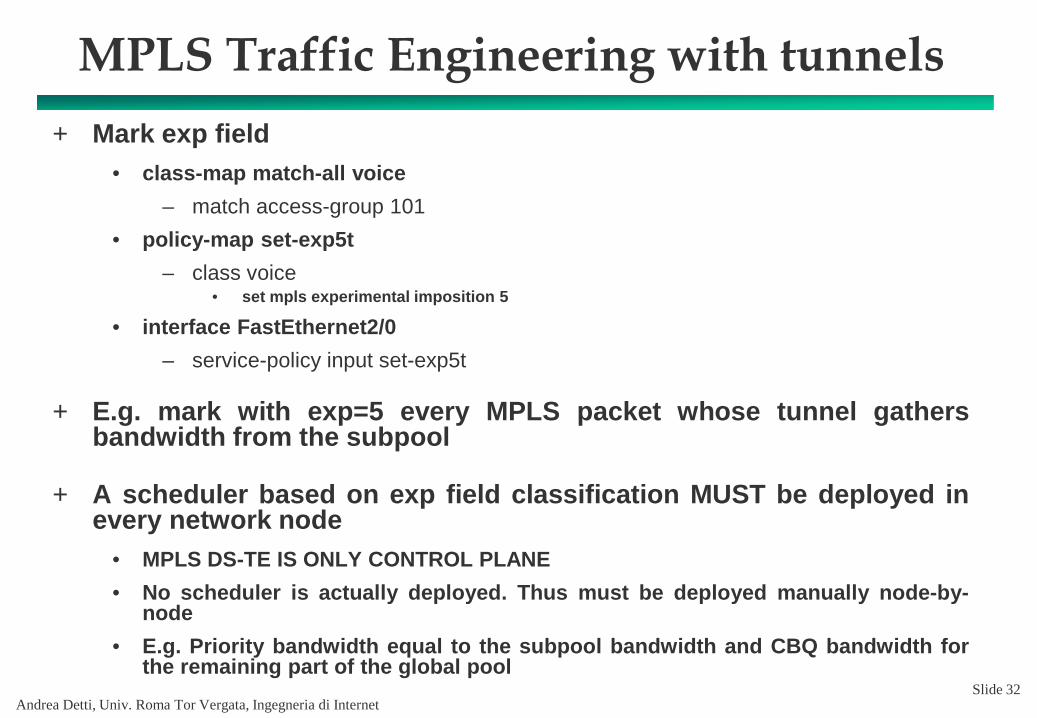
MPLS Traffic Engineering with tunnels+ Mark exp field
• class-map match-all voice– match access-group 101
• policy-map set-exp5t– class voice
• set mpls experimental imposition 5
• interface FastEthernet2/0– service-policy input set-exp5t
+ E.g. mark with exp=5 every MPLS packet whose tunnel gathersbandwidth from the subpool
+ A scheduler based on exp field classification MUST be deployed inevery network node
• MPLS DS-TE IS ONLY CONTROL PLANE• No scheduler is actually deployed. Thus must be deployed manually node-by-
node• E.g. Priority bandwidth equal to the subpool bandwidth and CBQ bandwidth for
the remaining part of the global poolSlide 32