Multi-Processor Programming in the Embedded System Curriculum · Multi-Processor Programming in the...
33
10/25/2008 1 TU/e Multi-Processor Programming in the Embedded System Curriculum Andreas Hansson 1 Benny Åkesson 1 Jef van Meerbergen 1,2 1 Eindhoven University of Technology 2 Philips Research
Transcript of Multi-Processor Programming in the Embedded System Curriculum · Multi-Processor Programming in the...

10/25/2008
1
TU/e
Multi-Processor Programming in the Embedded System Curriculum
Andreas Hansson1
Benny Åkesson1
Jef van Meerbergen1,2
1 Eindhoven University of Technology2 Philips Research

10/25/2008
2
TU/e
Outline
Introduction
Assignment
Structure
Discussion
10/25/2008
3
TU/e
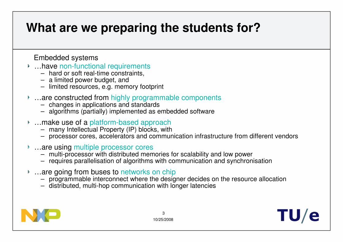
What are we preparing the students for?
…have non-functional requirements– hard or soft real-time constraints,– a limited power budget, and – limited resources, e.g. memory footprint
…are constructed from highly programmable components– changes in applications and standards– algorithms (partially) implemented as embedded software
…make use of a platform-based approach– many Intellectual Property (IP) blocks, with – processor cores, accelerators and communication infrastructure from different vendors
…are using multiple processor cores– multi-processor with distributed memories for scalability and low power– requires parallelisation of algorithms with communication and synchronisation
…are going from buses to networks on chip– programmable interconnect where the designer decides on the resource allocation– distributed, multi-hop communication with longer latencies
Embedded systems

10/25/2008
4
TU/e
How is it done at Eindhoven University?
Master program on embedded systems– joint program of EE and CS
Set of four courses, bottom-up– lower levels of design, i.e. logic and RTL synthesis, developing ALUs, multipliers,
memories etc, with focus on FPGAs– processor design, using the aforementioned blocks to build fully programmable
microprocessors, DSPs, ASIPs etc– networks on chip, focusing on the issues related to the communication– Embedded Systems Laboratory, hands-on design exercise, integrating the
previous courses and applying the lessons learnt in those courses

10/25/2008
5
TU/e
Course problem description
Put an embedded JPEG decoder on the market within 12 weeks– a platform with multiple embedded VLIW cores is given– port application code to embedded VLIW cores– efficiently map application to platform– quantitative benchmarking – system optimisation
Problem-driven assignment– design teams with four members– multi-disciplinary and multi-cultural cooperation

10/25/2008
6
TU/e
Course goals, low level
Using the development and simulation environment– GNU make, command line compiler, linker, debugger– upload code and data to memories using the Hive Run-Time library– memory map variables and communicate using distributed memories– set up network connections using the Æthereal Run-Time library– simulate the system using development environment and run the code on FPGA
Porting sequential C code to the target processor– identify which parts of the application that need modifications– handle file system and terminal I/O – statically allocate variables that are heap-allocated in the original code– use the frame buffer and peripherals on the FPGA board
Parallelising the application– orchestrate parallel execution using the Hive Run-Time library– exploit data level and task level parallelism in a JPEG decoder– explore different ways of implementing inter-processor communication– benchmark the decoder in simulation and on the FPGA
10/25/2008
7
TU/e
Course goals, high level
Learn how embedded and desktop programming differs
Learn how multi- and uni-processor programming differs
Learn how to evaluate the performance of an embedded application
Learn how design decisions impact the quality of the solution

10/25/2008
8
TU/e
Outline
Introduction
Assignment
Structure
Discussion

10/25/2008
9
TU/e
Application
Fully functional JPEG decoder written in sequential C
Like many other audio/video decoders, the algorithm consists of – Variable-length decoding (VLD), – Inverse-discrete cosine transform (IDCT) and – Color conversion (CC)
IDCTVLD CCJPEG BMP
JPEG decoder application

10/25/2008
10
TU/e
What is important for the course?
Reasonable amount of code
Makes use of dynamic memory and file system I/O
Retains the technical difficulties of other audio/video codecs
The algorithm is data dependent
Not trivially parallel, i.e. the VLD is inherently sequential
The code is small enough to fit in the local memory of a VLIW core (32 kb)
Results can be presented on screen
A JPEG decoder can be turned into M-JPEG, emphasising real-time

10/25/2008
11
TU/e
Multi-processor network-based archicecture
mem
Æthereal
slave
master
frame bufferslave
master
slav
e
host PC
VLIW
master
mem
slave FIFO
slave master FIFO
VLIW
master
mem
slave FIFO
slave master FIFO
VLIW
master
mem
slave FIFO
slave master FIFO
peripheralsslave
master

10/25/2008
12
TU/e
Silicon Hive VLIW template
Dramatically reduce control overhead
– expose all pipeline management to the instruction set
– move complexity to the compiler
– compiler explicitly schedules all pipeline stages
INST. MEM.
INST. REG.
INST. DECODER
FULLY-CONNECTEDNETWORK
RF
FU FU
PIP
ELI
NE
CO
NT
RO
LLE
R
HA
ZA
RD
DE
TE
CT
ION
BY
-PA
SS
NE
TW
OR
KS
&F
OR
WA
RD
ING
CO
NT
RO
L
SE
QU
EN
CIN
G L
OG
IC
PC
DATA MEM.
FULLY-CONNECTEDNETWORK
10/25/2008
13
TU/e
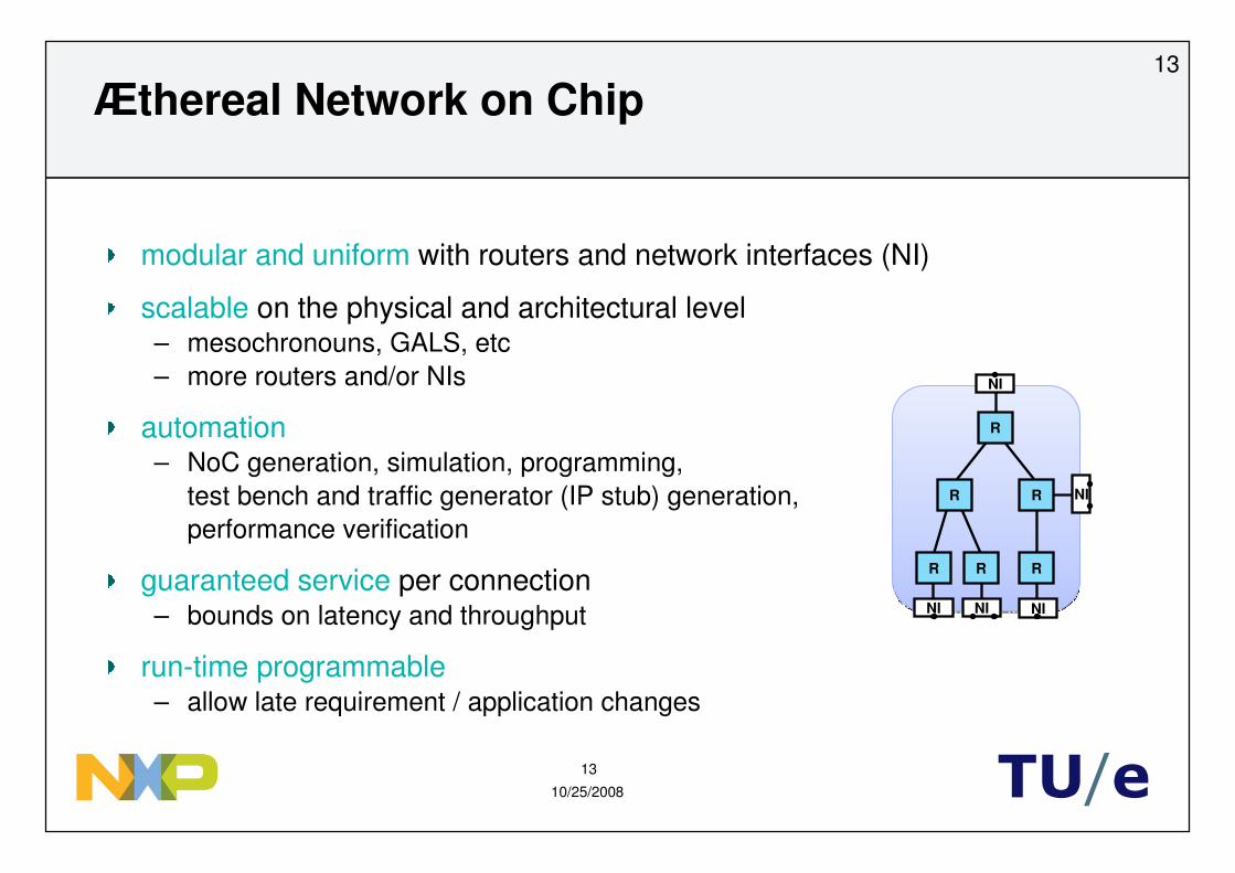
Æthereal Network on Chip
modular and uniform with routers and network interfaces (NI)
scalable on the physical and architectural level– mesochronouns, GALS, etc– more routers and/or NIs
automation– NoC generation, simulation, programming,
test bench and traffic generator (IP stub) generation,performance verification
guaranteed service per connection– bounds on latency and throughput
run-time programmable– allow late requirement / application changes
13
NI
NI
NI NI NI
R
R
R
R
R R
10/25/2008
14
TU/e
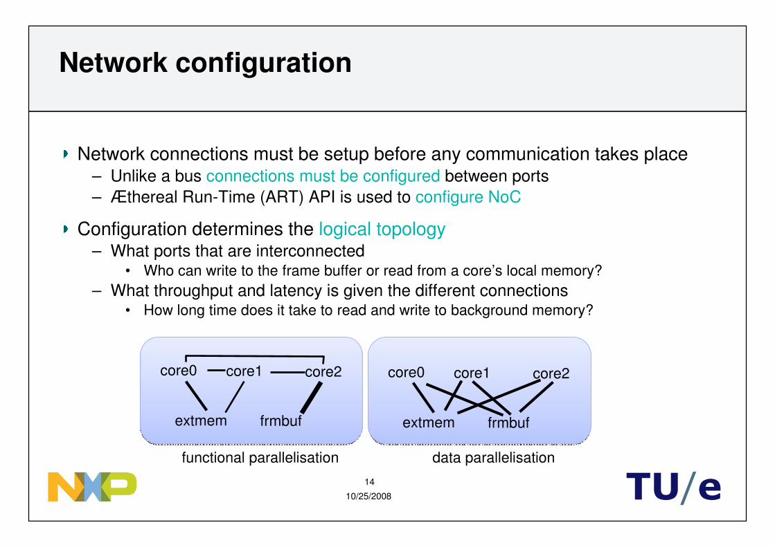
Network configuration
Network connections must be setup before any communication takes place– Unlike a bus connections must be configured between ports– Æthereal Run-Time (ART) API is used to configure NoC
Configuration determines the logical topology– What ports that are interconnected
• Who can write to the frame buffer or read from a core’s local memory?– What throughput and latency is given the different connections
• How long time does it take to read and write to background memory?
core0 core1 core2
extmem frmbuf
core0 core1 core2
extmem frmbuf
functional parallelisation data parallelisation

10/25/2008
15
TU/e
What is important for the course?
Multi-processor architecture with network on chip and multiple memories– communication infrastructure where resource dimensioning is done, but resource
assignment is left for the students– cores with fixed-point arithmetic, no operating system, no caches and explicit
memory management
Complete system simulation environment– one environment for functional verification, performance evaluation and
debugging, continuous refinement, etc
An actual hardware implementation on FPGA– face all the real problems, but gives tangible results
Industrially relevant IP components and tools– good for headhunting students for internships, hiring, etc

10/25/2008
16
TU/e
Outline
Introduction
Assignment
Structure
Discussion

10/25/2008
17
TU/e
Design-team roles
A design team has four members– Application expert: understands the JPEG standard and algorithm– Hardware expert: has detailed knowledge about the HW building blocks– Embedded programming expert: knows about porting and communication– Group leader: overviews project, distributes work and reports progress
Roles are determined within the first week

10/25/2008
18
TU/e
Step 1 – Install and familiarise
Getting of the ground– Students download, unpack and test source code distribution (JPEG decoder)– Acquiring documentation for the development environment, HW blocks and APIs
Familiarise with a simple ‘add’ example– deciphering Makefile and source code
Run the application on FPGA
Done during the first lab sessionDone during the first lab session

10/25/2008
19
TU/e
Step 2 – Single core solution
Run the decoder on a single VLIW core– the host reads a JPEG file and stores it as a byte array in system memory– the host uploads program code to the VLIW and starts its execution– the VLIW decodes image to frame buffer in system memory– The host downloads the contents of the system memory and writes it to a bitmap
host VLIWsystem memory
JPEG file
BMP file
JPEG array
frame buffer
JPEG array
frame buffer
Typically takes three to four weeksTypically takes three to four weeks

10/25/2008
20
TU/e
Step 3 – Distribute code over multiple cores
Code can be parallelised in many ways– functional partitioning (e.g. VLD, IDCT and CC), or data partitioning (tiling)– get a balanced load on the cores for high performance, measure stall cycles
core0
core2
core1
interconnect
systemmemory
host
Everything from one day for naïvetiling to six weeks for pipelining
Everything from one day for naïvetiling to six weeks for pipelining

10/25/2008
21
TU/e
Requirements
Group approved when– working single core solution– two working parallelisations of the code– benchmarks comparing solutions– presentation and report explaining approach and results– (compare with the low-level goals)
Grades determined by how well approach and results are explained(compare with the high-level goals)
Expected load: 9 hours per week– 3 + 3 = 6 hours in lab.– 3 hours outside lab.

10/25/2008
22
TU/e
Assessment
Oral presentations– short presentation per group (15 minutes)– individual presentations (10 minutes)
Written report per group (4 pages sig-alt template)
Meetings (~1 per week)– Group meetings– Group leader meetings– Application group– Benchmark committee
10/25/2008
23
TU/e
Outline
Introduction
Assignment
Structure
Discussion

10/25/2008
24
TU/e
Challenges
How to help without solving the problem for them?– minimising the problems involving understanding interfaces and I/O devices– tutorial exercises and demonstrative examples– inter-group discussions where problems/solutions are shared
How to debug the students non-working code?– show them how to do structured test and version control already from day one– …in real life there is no one out there to help you
How to cope with research-quality (buggy) tools?– we work closely with the tool developers, good for them, good for us
How to give even more freedom to the students?– not feasible with current 5 ECTS credits
How to set a grade on such a “fuzzy” course?– lots of time spent with the students has proven to make it easier than
we initially thought

10/25/2008
25
TU/e
Conclusions
Like other courses, we emphasize– the growing importance of software in embedded systems– resource-limited performance-oriented design – challenges in areas like personal time management and teamwork
In contrast to other courses, we stress– the challenges involved in going from uni- to multi- processor systems, and– the importance of communication and synchronisation
Based on student evaluations, we believe– that the Embedded System Laboratory delivers a level of realism that helps in
motivating the students and reinforcing the experiences gained during the course

10/25/2008
26
TU/e

10/25/2008
27
TU/e
Overview: JPEG encoding/decoding
-12-113-3
-112017-4
317-28-23
-3-4-2368
4488
4880
8800
8000
3489
4870
8700
9002
-10-1000
-1020200
020-30-20
00-2070
-12
-11
-11
3
20
3
-3
17
17
-3
-4
-28
-4
-23
-23
68
-10
-10
-10
0
20
0
0
20
20
0
0
-30
0
-20
-20
70
-1
-1
-1
0
2
0
0
2
2
0
0
-3
0
-2
-2
7
11110+7
11101+1
-3
+2
-2
-1
0
sym
11100
110
101
100
0
code
100
100
100
0
110
0
0
110
110
0
0
11100
0
101
101
11110
DCT ZZ Q VLC
IDCT ZZ IQ VLD+
-
offset
MCU block
Encoder
Decoder

10/25/2008
28
TU/e
functionunit
library
operationsemantic
library
machinedescription
high-levelC program
assemblycode
(C-syntax)
standardC compiler
processormodel
(C-syntax)
compiledsimulator
cycle count
binarycode
state view&
trace file
HDLcode
logic synth.place &route
area, speed, power
netlistlayout
simulation&
verification
spatialcompiler
processormodel
generator
assembler& linker
processorsimulator/generator
Internal design flow

10/25/2008
29
TU/e
functionunit
library
operationsemantic
library
machinedescription
high-levelC program
assemblycode
(C-syntax)
standardC compiler
processormodel
(C-syntax)
compiledsimulator
cycle count
binarycode
state view&
trace file
HDLcode
logic synth.place &route
area, speed, power
netlistlayout
simulation&
verification
spatialcompiler
processormodel
generator
assembler& linker
processorsimulator/generator
Internal design flow
hours to days minutes to hours
10/25/2008
30
TU/e
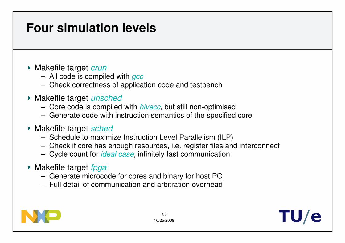
Four simulation levels
Makefile target crun– All code is compiled with gcc– Check correctness of application code and testbench
Makefile target unsched– Core code is compiled with hivecc, but still non-optimised– Generate code with instruction semantics of the specified core
Makefile target sched– Schedule to maximize Instruction Level Parallelism (ILP)– Check if core has enough resources, i.e. register files and interconnect– Cycle count for ideal case, infinitely fast communication
Makefile target fpga– Generate microcode for cores and binary for host PC– Full detail of communication and arbitration overhead
10/25/2008
31
TU/e
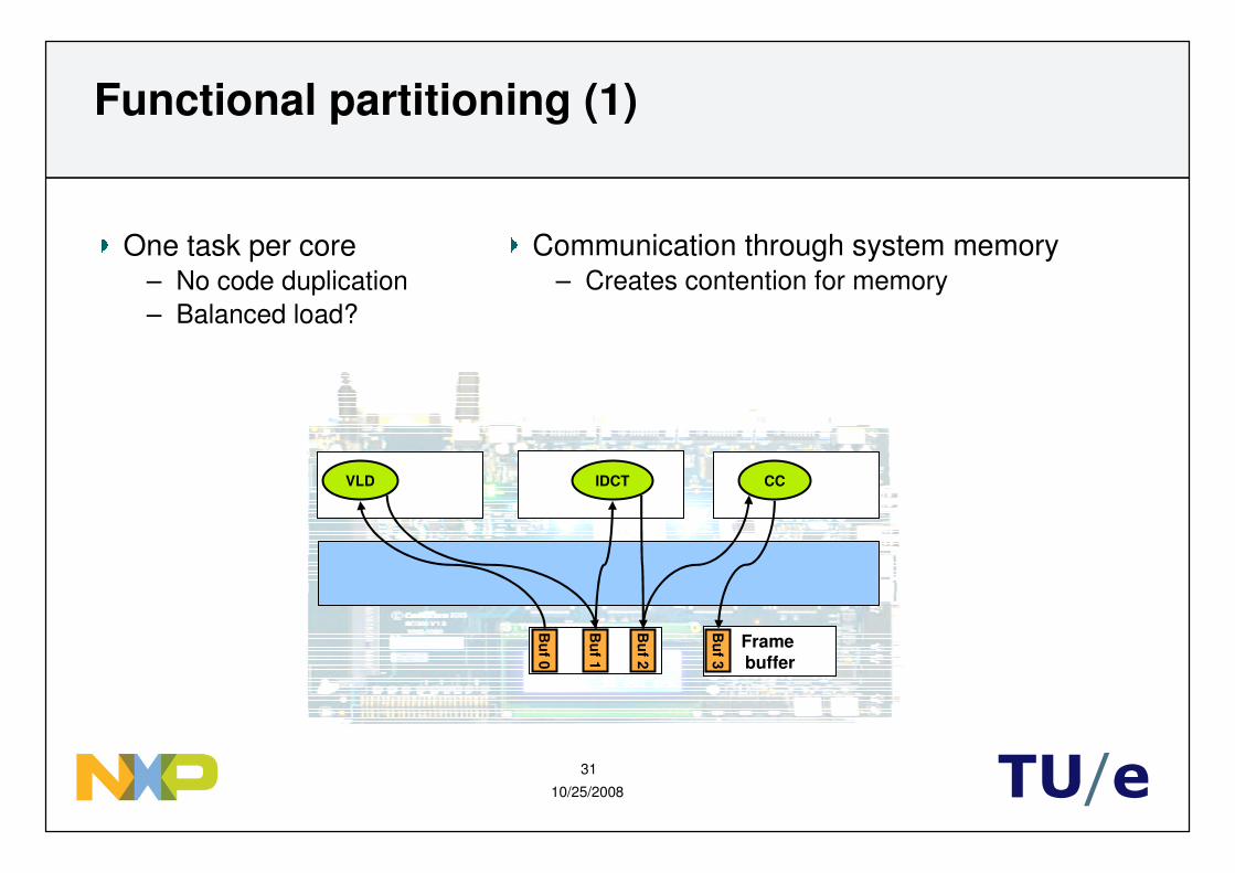
Functional partitioning (1)
Frame buffer
IDCTVLD CC
Bu
f0
Bu
f1
Bu
f2
Bu
f3
One task per core– No code duplication– Balanced load?
Communication through system memory– Creates contention for memory

10/25/2008
32
TU/e
Functional partitioning (2)
Mem Frame buffer
IDCTVLD CC
Bu
f0
Bu
f2
Bu
f3
Bu
f1
Some tasks read from local memory– Faster– Does communicated data fit?

10/25/2008
33
TU/e
Data partitioning
Mem Frame buffer
Bu
f3
Bu
f0
VLDIDCT
CC VLDIDCT
CC VLDIDCT
CC
All tasks on all cores– Code duplication– Each core decodes 1/3 image– Balanced load?
All cores must read entire image– Severe contention for memory