Multi-Point Replacement Hardware Parts Reference … Replacement Hardware Parts Reference Catalog...
14
Multi-Point Replacement Hardware Parts Reference Catalog For the following Hinged Patio Doors: #010153 – New 01/05 – PART 2 OF 2 Multi-Point Replacement Hardware Only For Additional Parts See Parts Reference Catalog #010973 PART 1 OF 2 – 09/03 Weather Shield Mfg., Inc. Medford, WI 54451 • 715-748-2100 • Weather Shield produced before 3/02 • ProShield produced before 8/04 • Visions produced before 2/04
Transcript of Multi-Point Replacement Hardware Parts Reference … Replacement Hardware Parts Reference Catalog...

Multi-Point Replacement Hardware
Parts Reference CatalogFor the following Hinged Patio Doors:
#010153 – New 01/05 – PART 2 OF 2
Multi-Point Replacement Hardware Only
For Additional Parts SeeParts Reference Catalog #010973 PART 1 OF 2 – 09/03
Weather Shield Mfg., Inc.Medford, WI 54451 • 715-748-2100
• Weather Shield produced before 3/02• ProShield produced before 8/04• Visions produced before 2/04

2 (01/05)
TABLE OF CONTENTS
Multi-Point Replacement Hardware Selection Chart . . . . . . . . . . . . . . . . . . . . . . . . . . . . . . . . . Page 3
Installation Instructions
Replacing Winkhaus and Roto Locking Gear With Hoppe –
Locking Gear – Part #941842, Top Extension – Part #941943 or
#941844 – No Shootbolts . . . . . . . . . . . . . . . . . . . . . . . . . . . . . . . . . . . . . . . . . . . . . . . Pages 4-7
Installation Instructions
Replacing Winkhaus Locking Gear With Hoppe –
Locking Gear – Part #941994, Middle Extension – Part #941995 & Top Extension
Part #941232 – With Shootbolts . . . . . . . . . . . . . . . . . . . . . . . . . . . . . . . . . . . . . . . . . . Pages 8-11
Installation Instructions
Switching From FUHR Automatic-Fire 3-Point or Manual Fire – From 1/89 through 3/96
To Hoppe Manual 3-Point Locking Gear
For 6-8 – 6-10 Units – Kit F1 Part #1175814 and
For 6-101/16 – 8-0 Units – Kit F2 Part #1175815 . . . . . . . . . . . . . . . . . . . . . . . . . . . . . . . . . . Pages 12-14
PURPOSE
This catalog is intended to assist you in
identifying and ordering multi-point replacement
hardware for your door.
Use the chart and diagrams on Page 3 to identi-
fy the “old hardware” on your door.
There are two separate kits for units built prior to
1/96 as noted in the middle of Page 3.
For all other doors, pick part numbers as appro-
priate, from the chart on the top of Page 3.
To successfully convert from old parts to new,
an entire set of new parts must be ordered.
You cannot intermix old and new hardware. Seethe installation instructions for more details.
Installation Instructions – Pages 4 through 14
explain how to change existing hardware over to
the new. Check the headings and pick the pages
that apply to your specific door.
The installation instructions are also available
separately, under their own document part
numbers, as listed below.
Page 3 . . . . . . . . . . . . . . . . . . . . . . . . .1180176
Page 4 thru 7 . . . . . . . . . . . . . . . . . . . . .1180173
Page 8 thru 11 . . . . . . . . . . . . . . . . . . . .1180175
Page 12 thru 14 . . . . . . . . . . . . . . . . . . .1175808
For additional assistance contact your Weather
Shield Customer Service Representative.
PARTS REFERENCE CATALOG GUIDE
Multi-Point Replacement Hardware
Parts Reference Catalog

3 (01/05)
Locking
Point #1
Locking
Point #2
Locking
Point #4
Locking
Point #3
Lock shownin lockedposition.
Measure from bottom of door panel (exclude any vinyl sweeps).
Measure your hardware while it is
in the locked position. Then
Select the appropriate part numbers from this chart for your order.NOTE: Bottom Extension includes locking gear and #8 x 5/8" machine screw.
Locking
Point #1
Locking
Point #3
Locking
Point #4
Bottom
Extension
Middle
Extension
Top
Extension
Main
Strike
Roller Strikes
(Quantity Provided)
9-1/2" 62-1/2" 83-1/2" 941842 N/A 941844 941356 941992 (qty. 2)
9-1/2" 62-1/2" 95-5/16" 941842 942098 942099 9413562941992 or 941993 (qty. 3)
9-1/2" 62-1/2" 109-3/8" 941842 942098 942101 9413562941992 or 941993 (qty. 3)
9-1/2" 62-1/2" 103-15/16" 941994 941995 942105 941356 941992 (qty. 3)
9-1/2" 69-7/16" N/A 941842 N/A 941843 9413562941992 or 941993 (qty. 2)
19-1/2"
169-7/16"
1N/A
1941994
1941995
1941232 941356
1941992 (qty. 2)
9-1/2" 69-7/16" 92-7/8" 941994 941995 942103 941356 941992 (qty. 3)
9-1/2" 83-1/2" N/A 941842 N/A 941844 941356 941993 (qty. 2)
22-1/16" 49" N/A 941455 N/A 941456 941356 941451 (qty. 2)
22-1/16" 49" 72-3/16" 941455 N/A 941457 941356 941451 (qty. 3)
1To use this gray highlighted row, insert must be 92-15/16" tall. If
it is not that tall use the line above.
2See drawings below to
order appropriate part.
Multi-Point Replacement HardwareFor the following Hinged Patio Doors: (roll pin hardware only)Weather Shield produced before 3/02 | ProShield produced before 8/04 | Visions produced before 2/04
NOTES
When ordering replacement parts, it will be necessary to
order a complete system, including:
• bottom extension
• middle extension (if applicable)
• top extension
• all strikes
Some parts may need to be trimmed to the correct
length.
1175814 (for 6-8 to 6-10 Heights
W/O Shootbolts) Contains:
Stainless Lock Gear w/btm exten #942093
Stainless 1220MM Top Extension #942094
Stainless Strike Plate #941356
Stainless Top Roller Plate #941992
Stainless #8x1-1/4" FHP Screws #960076
Stainless #8x5/8" FHP Screws #1019538
Instructions #1175808
1175815 (for 6-101/16 to 8-0 Heights
W/O Shootbolts) Contains:
Stainless Lock Gear w/btm exten #942093
Stainless 1570MM Top Extension #942095
Stainless Strike Plate #941356
Stainless Top Roller Plate #941992
Stainless #8x1-1/4" FHP Screws #960076
Stainless #8x5/8" FHP Screws #1019538
Instructions #1175808
Ord
er
#9
41
99
2
Ch
eck r
olle
r str
ike
s a
ga
inst
the
se
dim
en
sio
ns.
Ord
er
the
clo
se
st
ma
tch
to
th
e o
ld s
trik
e.
Ord
er
#9
41
99
3
Ro
lle
r S
trik
es
1-3/16" (Ref.)
2-1/2"(Ref.)
1-1/8" (Ref.)
3-1/8"(Ref.)
If Locking Point #1 measures 9-1/8", instead of
9-1/2", subtract 3/8" from every dimension.
If your unit was built prior to 1/96 use kit #1175814
or #1175815.
Part No. 1180176 1/05

4 (01/05)
Installation InstructionsReplacing Winkhaus and Roto Locking Gear WithHoppe Locking Gear – Part #941842 Including
Top Extension – Part #941843 or Part #941844 For Door Units From 6-8 to 8-0 Tall – NNoo SShhoooottbboollttss
Tools Needed
Hammer, Standard & Phillips Screwdriver, 1/4" &
1/2" Wide Wood Chisels, #2 & #3 Metric Hex
Wrenches, Measuring Tape, Pencil, Drop Cloth,
Hacksaw, Fine-Tooth Metal File, Utility Knife,
Replacement Hardware.
The replacement hardware includes:
Instructions
1. Open door. Remove interior handle set screw
(FIGURE 1). Use a #3 metric hex wrench.
Remove the interior handle. Slide the exterior
handle and shaft completely out of the door.
INTERIOR
HANDLE
SETSCREW
HEX
WRENCH
FIGURE 1
Improper use of hand and power tools could result in personal injury and/or
product damage. Follow equipment manufacturers’ instructions for safe
operation. Always wear safety glasses.
Quantities are for one door. A set, as listed, is required for each door.Item Qty. Part No.
Stainless lock gear w/bottom extension (no
shootbolt)1 941842
Stainless 829MM pin top extension (no
shootbolt)1 941843
OR Stainless 829MM pin top extension (no
shootbolt)1 941844
Stainless 3-piece roller plate – Winkhaus 2 941992
OR Stainless 3-piece roller plate – Roto 2 941993
Stainless latch/deadbolt strike plate 1 941356
#8 x 1-1/4" flat head Phillips stainless screws 12 960076
#8 x 5/8" flat head Phillips stainless screws 3 1019538
Installation Instructions 1 1180173
BOTTOM EXTENSION WITH
LOCK GEAR - PART #941842
TOP EXTENSION - PART #941843
BOTTOM EXTENSION WITH LOCK GEAR - PART #941842
TOP EXTENSION - PART #941844
Part No. 1180173 1/05

5 (01/05)
Installation InstructionsReplacing Winkhaus and Roto Locking Gear WithHoppe Locking Gear – Part #941842 Including
Top Extension – Part #941843 or Part #941844 For Door Units From 6-8 to 8-0 Tall – NNoo SShhoooottbboollttss
2. Remove key cylinder set screw from edge of
door (FIGURE 2). Then remove thumb turn/key
cylinder by sliding it to the interior.
3. Remove interior escutcheon plate screws that
hold the interior and exterior escutcheon plates
together (FIGURE 2). Remove plates.
4. Mark the door stile with a locator line drawn on
the stile and through the locator line embossed
on the lock case (FIGURE 2). This line ensures
that the new hardware goes back in the proper
place.
5. Remove screws from
the edge of the door
that hold the locking
rods to the door (FIG-
URE 3).
6. Remove locking gear
and rods from the
door.
7. Align new and old lock cases using the
embossed locator lines (FIGURE 4). The loca-
tor lines and the bottoms of the new and old
locking rods should line up. If not, cut the
bottom of the new locking rod even with the old.
Cut off using a hacksaw.
8. On new locking case, remove
label (FIGURE 5).
9. Squeeze tabs on plastic
shipping clip and pull clip
straight out (FIGURE 5).
10. Latch bolt and mis-
handling device must
have their slanted
sides facing the strike
plate. If the latch bolt
and mishandling
device face the wrong
direction, pull them
straight out from lock
case and rotate (FIG-
URE 6). Once rotat-
ed, release grip and
spring tension will
reseat them in the
lock case.
FIGURE 5
REMOVE
LABEL
SQUEEZE
TOGETHER
& PULL OUT.
LATCH
BOLT
MISHANDLING
DEVICE
DEADBOLT
PULL
OUT
AND
ROTATE
FIGURE 6
NEW LOCK CASE
EXISTING LOCK CASE
LOCATOR LINE
LOCATOR LINETOP
FIGURE 4
FIGURE 3
ESCUTCHEON
PLATE
ESCUTCHEON
PLATE
SCREW
ESCUTCHEON
PLATE
SCREW
LOCATOR
LINES
KEY
CYLINDER
SETSCREW
INTERIOR
EXTERIOR
HEX
WRENCH
THUMB
TURN/KEY
CYLINDER
LATCH
BOLT
FIGURE 2
Part No. 1180173 1/05
6 (01/05)
Installation InstructionsReplacing Winkhaus and Roto Locking Gear WithHoppe Locking Gear – Part #941842 Including
Top Extension – Part #941843 or Part #941844 For Door Units From 6-8 to 8-0 Tall – NNoo SShhoooottbboollttss
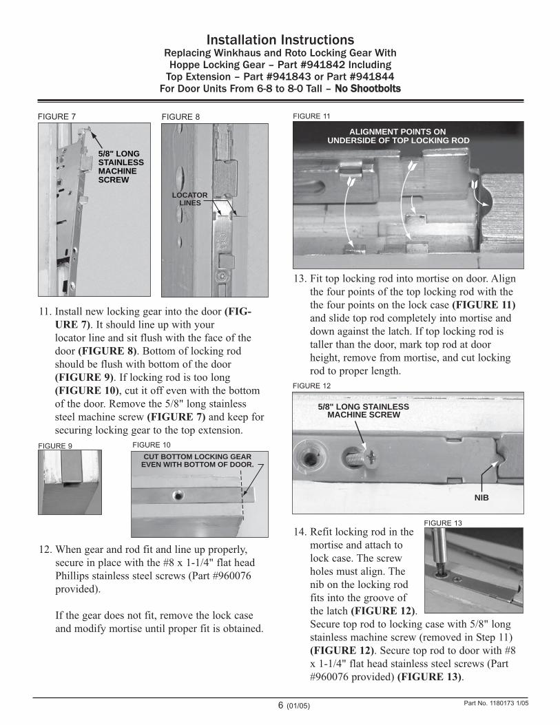
11. Install new locking gear into the door (FIG-
URE 7). It should line up with your
locator line and sit flush with the face of the
door (FIGURE 8). Bottom of locking rod
should be flush with bottom of the door
(FIGURE 9). If locking rod is too long
(FIGURE 10), cut it off even with the bottom
of the door. Remove the 5/8" long stainless
steel machine screw (FIGURE 7) and keep for
securing locking gear to the top extension.
12. When gear and rod fit and line up properly,
secure in place with the #8 x 1-1/4" flat head
Phillips stainless steel screws (Part #960076
provided).
If the gear does not fit, remove the lock case
and modify mortise until proper fit is obtained.
13. Fit top locking rod into mortise on door. Align
the four points of the top locking rod with the
the four points on the lock case (FIGURE 11)
and slide top rod completely into mortise and
down against the latch. If top locking rod is
taller than the door, mark top rod at door
height, remove from mortise, and cut locking
rod to proper length.
14. Refit locking rod in the
mortise and attach to
lock case. The screw
holes must align. The
nib on the locking rod
fits into the groove of
the latch (FIGURE 12).
Secure top rod to locking case with 5/8" long
stainless machine screw (removed in Step 11)
(FIGURE 12). Secure top rod to door with #8
x 1-1/4" flat head stainless steel screws (Part
#960076 provided) (FIGURE 13).
ALIGNMENT POINTS ON
UNDERSIDE OF TOP LOCKING ROD
FIGURE 11
NIB
5/8" LONG STAINLESSMACHINE SCREW
FIGURE 12
FIGURE 13
5/8" LONG
STAINLESS
MACHINE
SCREW
FIGURE 7
LOCATOR
LINES
FIGURE 8
FIGURE 9
CUT BOTTOM LOCKING GEAR
EVEN WITH BOTTOM OF DOOR.
FIGURE 10
Part No. 1180173 1/05

7 (01/05)
Installation InstructionsReplacing Winkhaus and Roto Locking Gear WithHoppe Locking Gear – Part #941842 Including
Top Extension – Part #941843 or Part #941844 For Door Units From 6-8 to 8-0 Tall – NNoo SShhoooottbboollttss
15. Remove the existing roller plates. Install the
stainless steel plates included with the new
parts. The new roller plate is a three-piece
assembly (FIGURE 14).
Install the base plate (FIGURE 15). Then the
two strike keepers (FIGURES 16 & 17).
16. Screw roller plates in place
using #8 x 1-1/4" flat head
Phillips stainless steel
screws (Part #960076 pro-
vided) (FIGURE 17).
17. Remove existing strike plate
from door jamb.
18. Test fit new strike plate to
door jamb (FIGURE 18).
Modify door jamb rout as
needed.
19. When strike plate fits prop-
erly, fasten with #8 x 5/8"
flat head Phillips stainless
steel screws (Part #1019538
provided).
20. Reinstall the interior and
exterior escutcheon plates,
key cylinder and handles.
NOTE: With door open,
locking gear will not
operate unless mishan-
dling device is pushed
in and held against
lock case (FIGURE
19).
21. Before shutting door, check
locking gear for proper
operation by operating
handle while fully depress-
ing mishandling device.
22. Shut door and check lock-
ing gear operation. Make
necessary adjustments to
provide smooth operation
and secure locking.
FIGURE 19
MISHANDLING
DEVICE
PUSH IN
FLUSH WITH
LOCK CASE
FIGURE 14
FIGURE 15 FIGURE 16
FIGURE 17
FIGURE 18
Part No. 1180173 1/05

8 (01/05)
Installation InstructionsReplacing Winkhaus Locking Gear With
Hoppe Locking Gear – Part #941994, Middle Extension – Part #941995 & Top Extension – Part #941232
For Door Units From 7-2-5/8 to 8-0 Tall WWiitthh SShhoooottbboollttss
Tools Needed
Hammer, Standard & Phillips Screwdriver, 1/4"
& 1/2" Wide Wood Chisels, #2 & #3 Metric Hex
Wrenches, Measuring Tape, Pencil, Drop Cloth,
Hacksaw, Utility Knife, Fine-Tooth Metal File,
Replacement Hardware.
The replacement hardware includes:
Instructions
1. Open door. Remove interior handle set screw
(FIGURE 1). Use a
#3 metric hex wrench.
Remove the interior
handle. Slide the exte-
rior handle and shaft
completely out of the
door.
2. Remove key cylinder set screw from edge of
door (FIGURE 2). Then remove thumb turn/key
cylinder by sliding it to the interior.
3. Remove interior escutcheon plate screws that
hold the interior and exterior escutcheon plates
together (FIGURE 2). Remove plates.
4. Before pulling hardware from the door mark the
door stile with a locator line drawn on the stile
and through the locator line embossed on the
lock case (FIGURE 2). This line ensures that
the new hardware goes back in the proper place.
INTERIOR
HANDLE
SETSCREW
HEX
WRENCH
ESCUTCHEON
PLATE
ESCUTCHEON
PLATE
SCREW
ESCUTCHEON
PLATE
SCREW
LOCATOR
LINES
KEY
CYLINDER
SETSCREW
INTERIOR
EXTERIOR
HEX
WRENCH
THUMB
TURN/KEY
CYLINDER
LATCH
BOLT
FIGURE 1
FIGURE 2
Improper use of hand and power tools could result in personal injury and/or
product damage. Follow equipment manufacturers’ instructions for safe
operation. Always wear safety glasses.
Quantities are for one door. A set, as listed, is required for each door.Item Qty. Part No.
Stainless lock gear w/bottom extension (with
shootbolt)1 941994
Stainless 829MM pin mid extension 1 941995
Stainless top extension (with shootbolt) 1 941232
Stainless 3-piece roller plate – Winkhaus 2 941992
Stainless latch/deadbolt strike plate 1 941356
#8 x 1-1/4" flat head Phillips stainless screws 12 960076
#8 x 5/8" flat head Phillips stainless screws 3 1019538
Installation Instructions 1 1180175
BOTTOM EXTENSION WITH LOCK GEARAND SHOOTBOLT PART #941994
MID EXTENSIONPART #941995
TOP EXTENSION WITHSHOOTBOLT PART #941232
Part No. 1180175 1/05
9 (01/05)
Installation InstructionsReplacing Winkhaus Locking Gear With
Hoppe Locking Gear – Part #941994, Middle Extension – Part #941995 & Top Extension – Part #941232
For Door Units From 7-2-5/8 to 8-0 Tall WWiitthh SShhoooottbboollttss
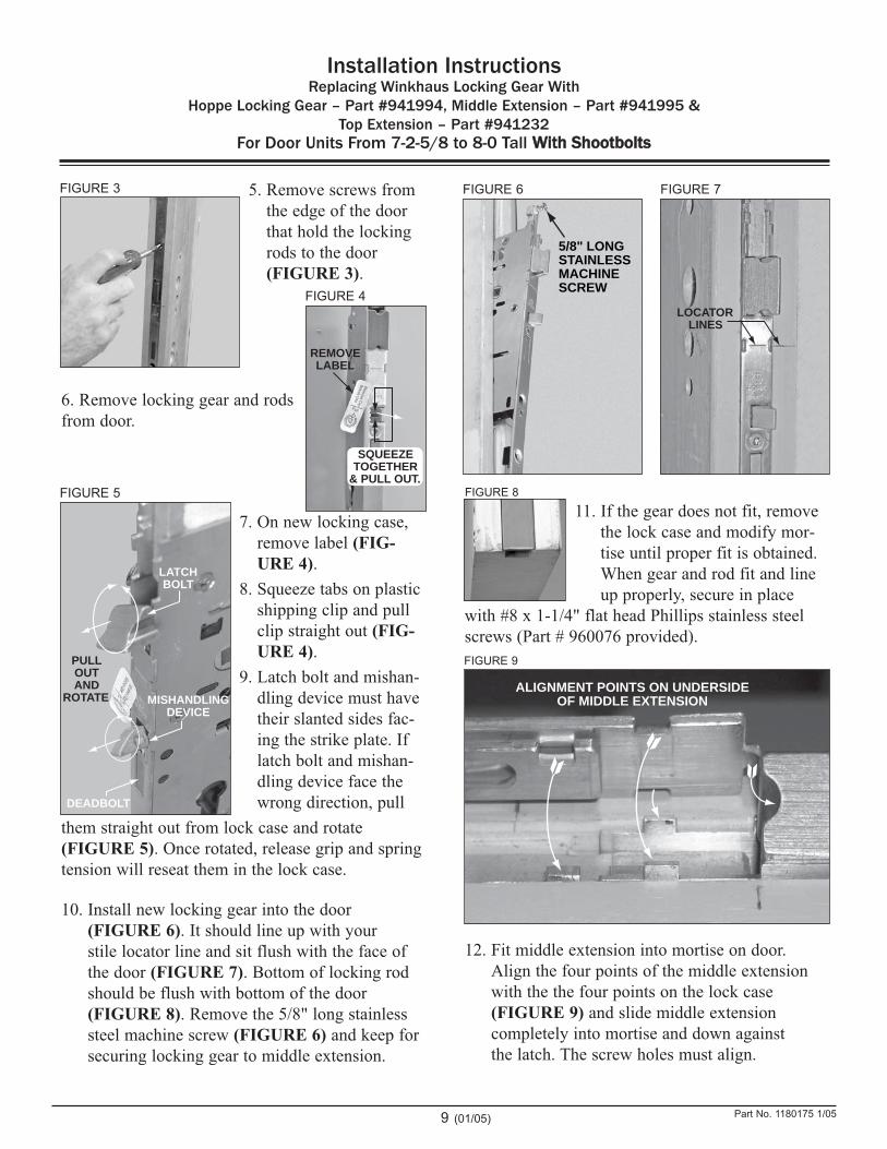
5. Remove screws from
the edge of the door
that hold the locking
rods to the door
(FIGURE 3).
6. Remove locking gear and rods
from door.
7. On new locking case,
remove label (FIG-
URE 4).
8. Squeeze tabs on plastic
shipping clip and pull
clip straight out (FIG-
URE 4).
9. Latch bolt and mishan-
dling device must have
their slanted sides fac-
ing the strike plate. If
latch bolt and mishan-
dling device face the
wrong direction, pull
them straight out from lock case and rotate
(FIGURE 5). Once rotated, release grip and spring
tension will reseat them in the lock case.
10. Install new locking gear into the door
(FIGURE 6). It should line up with your
stile locator line and sit flush with the face of
the door (FIGURE 7). Bottom of locking rod
should be flush with bottom of the door
(FIGURE 8). Remove the 5/8" long stainless
steel machine screw (FIGURE 6) and keep for
securing locking gear to middle extension.
11. If the gear does not fit, remove
the lock case and modify mor-
tise until proper fit is obtained.
When gear and rod fit and line
up properly, secure in place
with #8 x 1-1/4" flat head Phillips stainless steel
screws (Part # 960076 provided).
12. Fit middle extension into mortise on door.
Align the four points of the middle extension
with the the four points on the lock case
(FIGURE 9) and slide middle extension
completely into mortise and down against
the latch. The screw holes must align.
5/8" LONG
STAINLESS
MACHINE
SCREWFIGURE 4
REMOVE
LABEL
SQUEEZE
TOGETHER
& PULL OUT.
LATCH
BOLT
MISHANDLING
DEVICE
DEADBOLT
PULL
OUT
AND
ROTATE
FIGURE 5
FIGURE 6
LOCATOR
LINES
FIGURE 7
FIGURE 8
ALIGNMENT POINTS ON UNDERSIDE
OF MIDDLE EXTENSION
FIGURE 9
FIGURE 3
Part No. 1180175 1/05

10 (01/05)
Installation InstructionsReplacing Winkhaus Locking Gear With
Hoppe Locking Gear – Part #941994, Middle Extension – Part #941995 & Top Extension – Part #941232
For Door Units From 7-2-5/8 to 8-0 Tall WWiitthh SShhoooottbboollttss
The nib on the middle extension fits into the
groove of the latch (FIGURE 10). Secure middle
extension to locking case with 5/8" long stainless
machine screw (removed in Step 10) (FIGURE
10). Secure middle extension to door with #8 x
1-1/4" flat head stainless steel screws (Part
#960076 provided) (FIGURE 11).
13. Measure from the top of the door to the top of
the installed middle extension (FIGURE 12).
Mark top extension at this length.
14. With a hacksaw, cut at bottom of the top exten-
sion to achieve this length. DO NOT CUT
AT TOP OR SHOOTBOLT WILL BE
DAMAGED (FIGURE 13)!
15. The toothed bar on the underside of the top
extension engages the toothed receiver on the
top of the middle extension (FIGURE 14).
Remove any burrs or metal particles that would
prevent a good fit between the top and middle
extensions.
16. Turn top extension so toothed bar is down.
Engage bar into toothed receiver on middle
extension and lay rest of top extension into
door mortise (FIGURE 15). Secure top
extension in door with #8 x 1-1/4" flat head
stainless steel screws (Part #960076 provided).
NIB
5/8" LONG STAINLESSMACHINE SCREW
FIGURE 10
FIGURE 12
FIGURE 11
TOP EXTENSION
PART #941232MIDDLE EXTENSION
PART #941995
MEASURE FROM TOP OF DOOR TO
TOP OF INSTALLED MIDDLE EXTENSION.
CUT TO LENGTH IN THIS AREA ONLY!
MIDDLE EXTENSION
TOP
EXTENSION
DO NOT CUT HERE!
SHOOTBOLT WILL
BE DAMAGED.
FIGURE 13
TOOTHED BAR
TOOTHED
RECEIVER
TOP OUTSIDE OF
MIDDLE EXTENSION
UNDERSIDE OF
TOP EXTENSION
FIGURE 14
FIGURE 15
Part No. 1180175 1/05

11 (01/05)
Installation InstructionsReplacing Winkhaus Locking Gear With
Hoppe Locking Gear – Part #941994, Middle Extension – Part #941995 & Top Extension – Part #941232
For Door Units From 7-2-5/8 to 8-0 Tall WWiitthh SShhoooottbboollttss
17. Remove the existing roller plates. Install the
stainless steel plates included with the new
parts. The new roller plate is a three-piece
assembly (FIGURE 16).
Install the base plate (FIGURE 17). Then the
two strike keepers (FIGURES 18 & 19).
18. Screw roller plates in place
using #8 x 1-1/4" flat head
Phillips stainless steel
screws (Part #960076
provided) (FIGURE 19).
19. Remove existing strike plate
from door jamb.
20. Test fit new strike plate to
door jamb (FIGURE 20).
Modify door jamb rout as
needed.
21. When strike plate fits prop-
erly, fasten with #8 x 5/8"
flat head Phillips stainless
steel screws (Part #1019538
provided).
22. Reinstall the interior and
exterior escutcheon plates,
key cylinder and handles.
NOTE: With door open,
locking gear will not
operate unless mishan-
dling device is pushed
in and held against
lock case (FIGURE
21).
23. Before shutting door, check
locking gear for proper
operation by operating
handle while fully depress-
ing mishandling device.
24. Shut door and check lock-
ing gear operation. Make
necessary adjustments to
provide smooth operation
and secure locking.
FIGURE 21
MISHANDLING
DEVICE
PUSH IN
FLUSH WITH
LOCK CASE
FIGURE 16
FIGURE 17 FIGURE 18
FIGURE 19
FIGURE 20
Part No. 1180175 1/05

12 (01/05)
Installation InstructionsSwitching From FUHR Automatic-Fire 3-Point or Manual-Fire – From 1/89 through 3/96
To Hoppe Manual 3-Point Locking Gear For 6-8 – 6-10 Units– Kit F1 Part #1175814
For 6-10-1/16 – 8-0 Units – Kit F2 Part #1175815
Tools Needed
Hammer, Standard & Phillips Screwdriver, 1/4"
& 1/2" Wide Wood Chisels, #2 & #3 Metric Hex
Wrenches, Measuring Tape, Pencil, Drop Cloth,
Hacksaw, Utility Knife, Replacement Hardware.
The replacement hardware kit includes
Instructions
1. Open door. Remove interior setscrew from han-
dle. Use a #3 metric hex wrench. Slide the exte-
rior handle and shaft out of the door and locking
gear (FIGURE 1).
2. Remove key cylinder setscrew from edge of
door. Then remove thumb turn/key cylinder by
sliding to the interior (FIGURE 2).
3. Remove interior screws that hold the interior and
exterior escutcheon plates together (FIGURE 2).
Remove plates.
4. Remove screws from
the edge of the door
that hold the locking
rods to the door
(FIGURE 3).
5. Before pulling hard-
ware from the door
mark the door stile
with a locator line
drawn on the stile and
through the locator line embossed on the lock
case (FIGURE 2). This line ensures that the
new hardware goes back in the proper place.INTERIOR
HANDLE
SETSCREW
HEX
WRENCH
ESCUTCHEON
PLATE
ESCUTCHEON
PLATE
SCREW
ESCUTCHEON
PLATE
SCREW
LOCATOR
LINES
KEY
CYLINDER
SETSCREW
INTERIOR
EXTERIOR
HEX
WRENCH
THUMB
TURN/KEY
CYLINDER
LATCH
BOLT
FIGURE 1
FIGURE 2
FIGURE 3
Improper use of hand and power tools could result in personal injury and/or
product damage. Follow equipment manufacturers’ instructions for safe
operation. Always wear safety glasses.
Item Qty. Part No.
Lock case with bottom locking rod –
Hoppe. 1 942093
Top locking rod for 6-8 and
6-10 doors – Hoppe1 942094
OR (based on door height)
Top locking rod for 6-10 1/16 through
8-0 doors – Hoppe1 942095
Strike plate – stainless steel 1 941356
Top roller plate – stainless steel 1 941992
#8 x 1-1/4" flat head Phillips stainless
steel screws20 960076
#8 x 5/8" flat head Phillips stainless
steel screws6 1019538
Installation Instructions 1 1175808
Part No. 1175808 8/04

13 (01/05)
Installation InstructionsSwitching From FUHR Automatic-Fire 3-Point or Manual-Fire – From 1/89 through 3/96
To Hoppe Manual 3-Point Locking Gear For 6-8 – 6-10 Units– Kit F1 Part #1175814
For 6-10-1/16 – 8-0 Units – Kit F2 Part #1175815
6. Align new and old lock cases using the
embossed locator lines (FIGURE 4). Mark the
bottom of the new locking rod to the length of
the existing locking rod. Cut the bottom of the
new locking rod even with the old. Cut off using
a hacksaw.
7. Remove label covering mishan-
dling device (FIGURE 5).
8. Squeeze tabs on plastic
shipping clip and pull clip
straight out (FIGURE 5).
9. Latch bolt and mishan-
dling device must have
their slanted sides facing
the strike plate. If the
latch bolt and mishan-
dling device face the
wrong way, pull item
straight out from lock
case and rotate (FIG-
URE 6). Once rotated,
release grip and spring
tension will reseat them
in the lock case.
10. Try installing new locking gear into the door
(FIGURE 7). It should line up with your
locator line and sit flush with the face of the
door (FIGURE 8). If it lines up properly,
secure in place with the #8 x 1-1/4" flat head
Phillips stainless steel screws. If the gear
does not fit, remove the lock case and modify
mortise until proper fit is obtained.
11. Install top locking
rod into mortise
on door and onto
the lock case
tangs. The screw
holes must align.
The nib on the
locking rod fits
into the groove of
the latch (FIG-
URE 9).
FIGURE 5
REMOVE
LABEL
SQUEEZE
TOGETHER
& PULL OUT.
LATCH
BOLT
MISHANDLING
DEVICE
DEADBOLT
PULL
OUT
AND
ROTATE
FIGURE 6
FIGURE 7
LOCATOR
LINES
LOCK
CASE
TANGS
SCREW
HOLES
NIB
LOCATOR
LINES
TOP
LOCKING
ROD
LATCH
FIGURE 8
FIGURE 9
NEW LOCK CASE
EXISTING LOCK CASE
LOCATOR LINE
LOCATOR LINETOP
FIGURE 4
Part No. 1175808 8/04

14 (01/05)
Installation InstructionsSwitching From FUHR Automatic-Fire 3-Point or Manual-Fire – From 1/89 through 3/96
To Hoppe Manual 3-Point Locking Gear For 6-8 – 6-10 Units– Kit F1 Part #1175814
For 6-10-1/16 – 8-0 Units – Kit F2 Part #1175815
12. Remove existing top roller plate.
The existing top roller plate
can be reused or the new
plate, included in the kit,
can be installed.
For Existing Roller Plate
13. Use existing roller plate
as template and extend top
of mortise 9/16" upwards
(FIGURE 10).
For New Roller Plate
13. Use new roller plate as a
template. Align new plate’s
bottom with bottom of
existing mortise and mark
revisions to mortise
(FIGURE 11).
14. Choose one of the roller
plates, modify the mortise
as shown, and screw roller
plate in place using #8 x
5/8" flat head Phillips stainless steel screws.
15. Remove existing strike plate from door jamb.
16. Use the new strike plate from kit as a template.
Align new plate at bottom
of mortise (FIGURE 12).
Slide into mortise until
outer edge of strike aligns
with edge of door frame
(FIGURE 13). With a
pencil, trace around strike
plate to mark areas that
need to be removed from
the mortise (FIGURE 14).
17. Remove areas shown in (FIGURE 14) and test
fit new strike plate. Modify strike plate mortise
as needed until new strike plate fits flush with
edge and surface of side jamb.
18. Fasten new strike plate with #8 x 1-1/4" flat
head Phillips stainless steel screws.
19. Install the interior and exterior escutcheon
plates, key cylinder and handles.
20. Check locking gear for proper operation.
Note: The replacement locking gear handles
have to be lifted to operate the pins on
the door edge.
FIGURE 12
FIGURE 13
TO BE
CHISELED
OUT
FIGURE 14
TOP
EXISTING
ROLLER
PLATE
RAISED
9/16˝
9/16˝
FIGURE 10
FIGURE 11
9/16˝
NEW
ROLLER
PLATE
EXISTING
ROLLER
PLATE
RAISED
9/16˝
ADDITIONAL
MATERIAL TO
CHISEL OUT
FOR NEW
ROLLER PLATE.
Part No. 1175808 8/04