Multi-physics electric motor simulation workflow · Multi-physics electric motor simulation...
37
Multi-physics electric motor simulation workflow James Goss CADFEM Ireland 13 th October 2017
-
Upload
nguyenkiet -
Category
Documents
-
view
231 -
download
0
Transcript of Multi-physics electric motor simulation workflow · Multi-physics electric motor simulation...
Multi-physics electric motor simulation workflow
James Goss
CADFEM Ireland 13th October 2017
2
Overview
Introduction to Motor Design Ltd
Motor-CAD software
Electromagnetic, Thermal, efficiency mapping & drive cycle analysis
Application examples
Links to Ansys
Link to OptiSlang
E-motor analysis using Ansys – Jens Otto
3
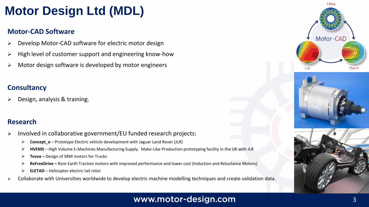
Motor Design Ltd (MDL)
Motor-CAD Software
Develop Motor-CAD software for electric motor design
High level of customer support and engineering know-how
Motor design software is developed by motor engineers
Consultancy
Design, analysis & training.
Research
Involved in collaborative government/EU funded research projects: Concept_e – Prototype Electric vehicle development with Jaguar Land Rover (JLR)
HVEMS – High Volume E-Machines Manufacturing Supply. Make-Like-Production prototyping facility in the UK with JLR
Tevva – Design of SRM motors for Trucks
ReFreeDrive – Rare Earth Traction motors with improved performance and lower cost (Induction and Reluctance Motors)
ELETAD – Helicopter electric tail rotor
Collaborate with Universities worldwide to develop electric machine modelling techniques and create validation data.
4
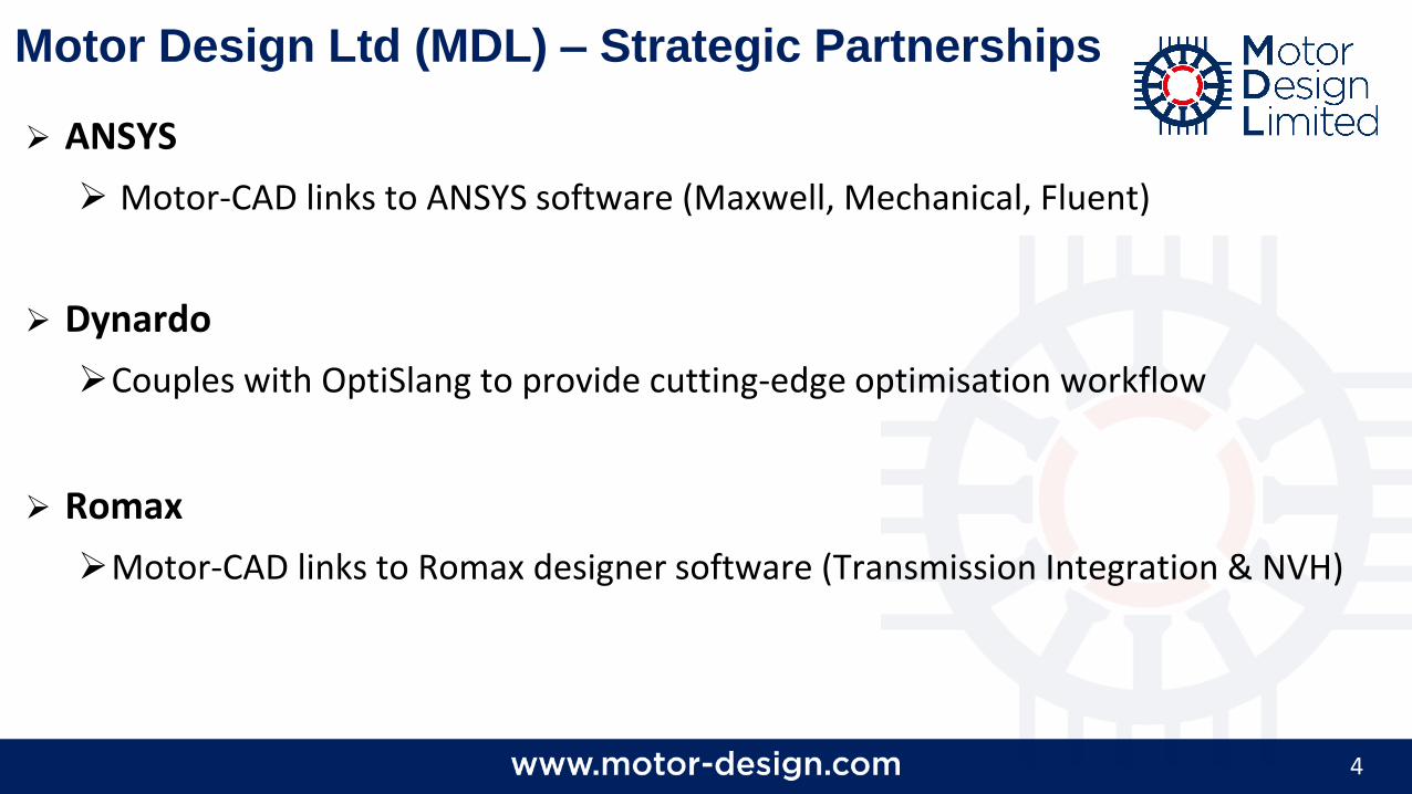
Motor Design Ltd (MDL) – Strategic Partnerships
ANSYS
Motor-CAD links to ANSYS software (Maxwell, Mechanical, Fluent)
Dynardo
Couples with OptiSlang to provide cutting-edge optimisation workflow
Romax
Motor-CAD links to Romax designer software (Transmission Integration & NVH)
5
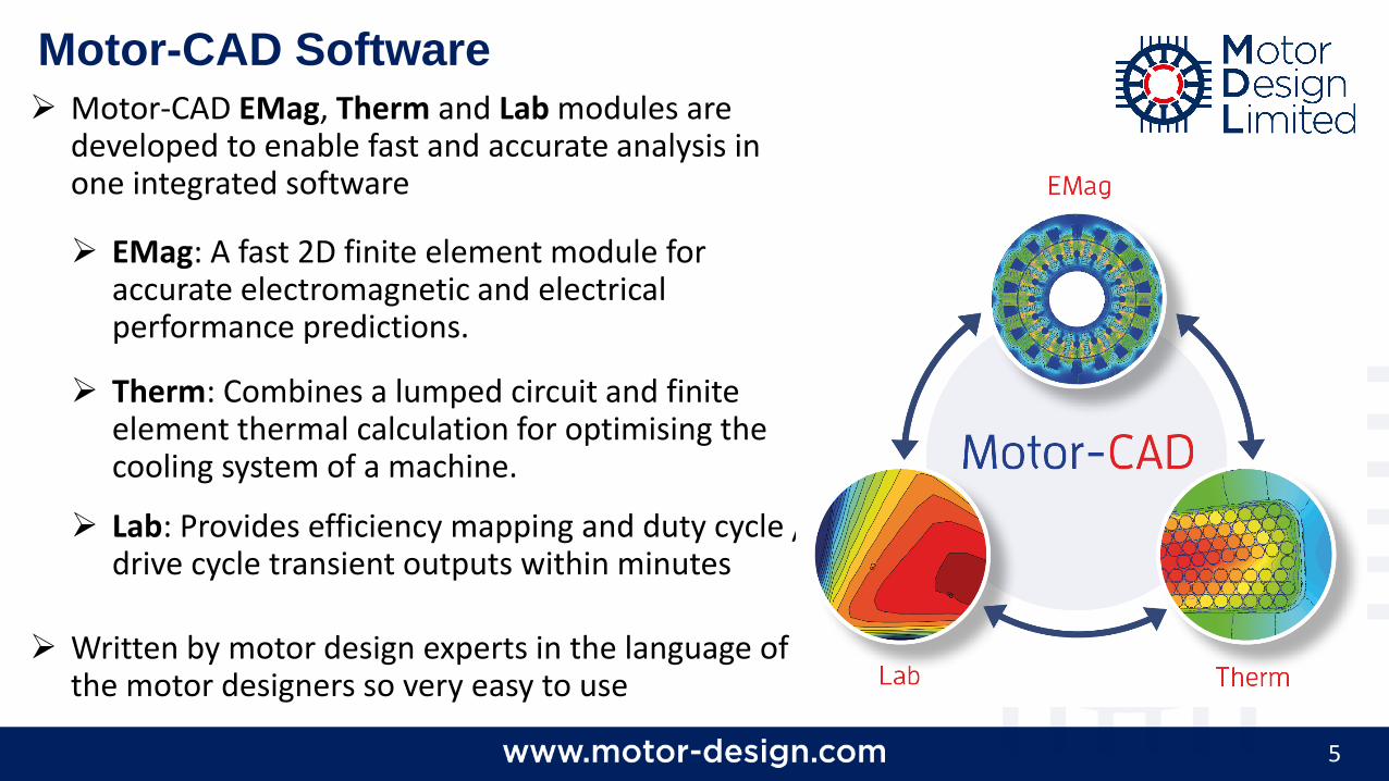
Motor-CAD Software Motor-CAD EMag, Therm and Lab modules are
developed to enable fast and accurate analysis in one integrated software
EMag: A fast 2D finite element module for accurate electromagnetic and electrical performance predictions.
Therm: Combines a lumped circuit and finite element thermal calculation for optimising the cooling system of a machine.
Lab: Provides efficiency mapping and duty cycle / drive cycle transient outputs within minutes
Written by motor design experts in the language of the motor designers so very easy to use
6
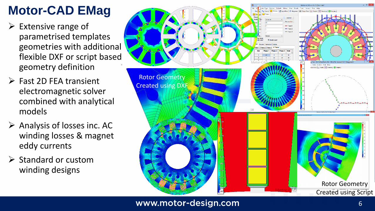
Motor-CAD EMag
Extensive range of parametrised templates geometries with additional flexible DXF or script based geometry definition
Fast 2D FEA transient electromagnetic solver combined with analytical models
Analysis of losses inc. AC winding losses & magnet eddy currents
Standard or custom winding designs
Rotor Geometry Created using Script
Rotor Geometry Created using DXF
7
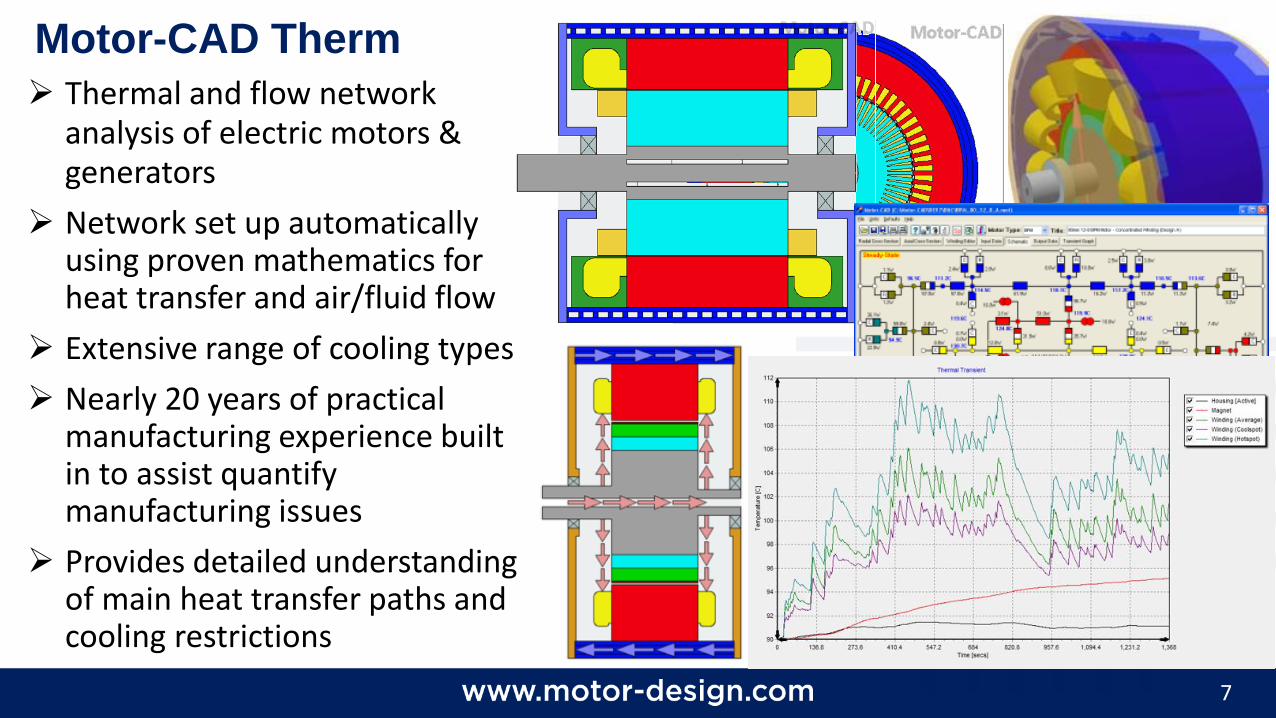
Motor-CAD Therm
Thermal and flow network analysis of electric motors & generators
Network set up automatically using proven mathematics for heat transfer and air/fluid flow
Extensive range of cooling types
Nearly 20 years of practical manufacturing experience built in to assist quantify manufacturing issues
Provides detailed understanding of main heat transfer paths and cooling restrictions
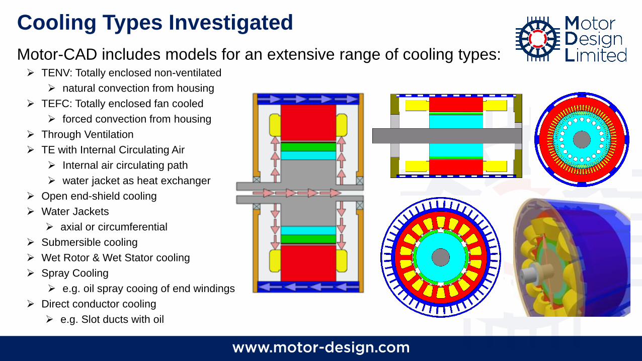
Cooling Types Investigated
Motor-CAD includes models for an extensive range of cooling types: TENV: Totally enclosed non-ventilated
natural convection from housing
TEFC: Totally enclosed fan cooled
forced convection from housing
Through Ventilation
TE with Internal Circulating Air
Internal air circulating path
water jacket as heat exchanger
Open end-shield cooling
Water Jackets
axial or circumferential
Submersible cooling
Wet Rotor & Wet Stator cooling
Spray Cooling
e.g. oil spray cooing of end windings
Direct conductor cooling
e.g. Slot ducts with oil
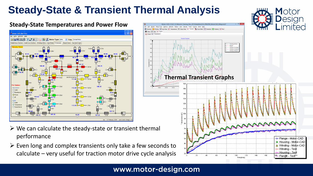
Steady-State & Transient Thermal Analysis
We can calculate the steady-state or transient thermal performance
Even long and complex transients only take a few seconds to calculate – very useful for traction motor drive cycle analysis
Thermal Transient Graphs
Steady-State Temperatures and Power Flow
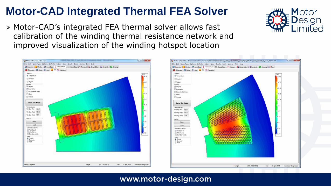
Motor-CAD Integrated Thermal FEA Solver
Motor-CAD’s integrated FEA thermal solver allows fast calibration of the winding thermal resistance network and improved visualization of the winding hotspot location
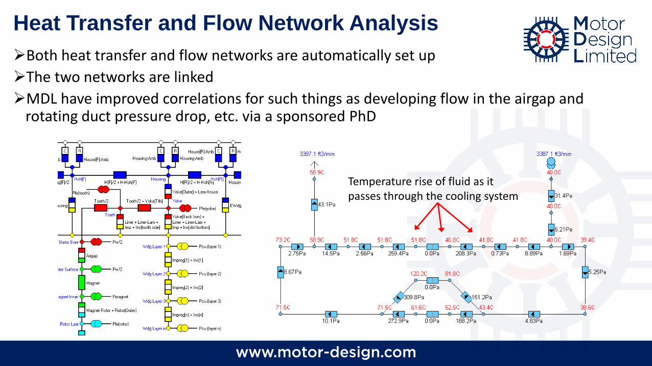
Heat Transfer and Flow Network Analysis
Both heat transfer and flow networks are automatically set up
The two networks are linked
MDL have improved correlations for such things as developing flow in the airgap and rotating duct pressure drop, etc. via a sponsored PhD
Temperature rise of fluid as it passes through the cooling system
12
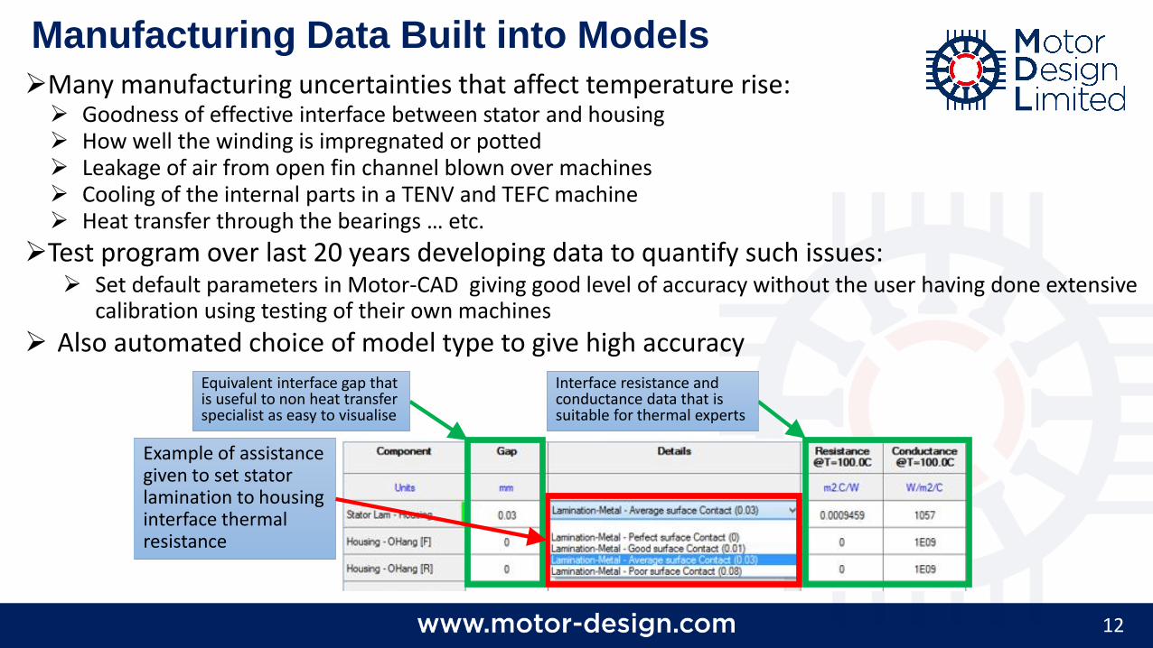
Manufacturing Data Built into Models
Many manufacturing uncertainties that affect temperature rise: Goodness of effective interface between stator and housing How well the winding is impregnated or potted Leakage of air from open fin channel blown over machines Cooling of the internal parts in a TENV and TEFC machine Heat transfer through the bearings … etc.
Test program over last 20 years developing data to quantify such issues: Set default parameters in Motor-CAD giving good level of accuracy without the user having done extensive
calibration using testing of their own machines
Also automated choice of model type to give high accuracy
Example of assistance given to set stator lamination to housing interface thermal resistance
Interface resistance and conductance data that is suitable for thermal experts
Equivalent interface gap that is useful to non heat transfer specialist as easy to visualise
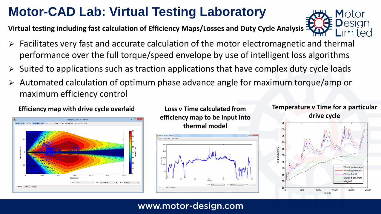
Facilitates very fast and accurate calculation of the motor electromagnetic and thermal performance over the full torque/speed envelope by use of intelligent loss algorithms
Suited to applications such as traction applications that have complex duty cycle loads
Automated calculation of optimum phase advance angle for maximum torque/amp or maximum efficiency control
Motor-CAD Lab: Virtual Testing Laboratory
Efficiency map with drive cycle overlaid Loss v Time calculated from efficiency map to be input into
thermal model
Temperature v Time for a particular drive cycle
Virtual testing including fast calculation of Efficiency Maps/Losses and Duty Cycle Analysis
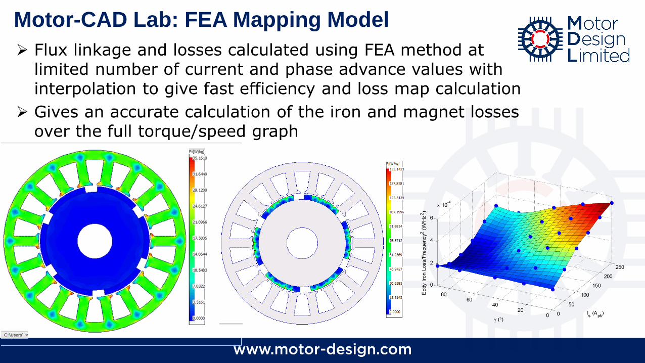
Flux linkage and losses calculated using FEA method at limited number of current and phase advance values with interpolation to give fast efficiency and loss map calculation
Gives an accurate calculation of the iron and magnet losses over the full torque/speed graph
Motor-CAD Lab: FEA Mapping Model
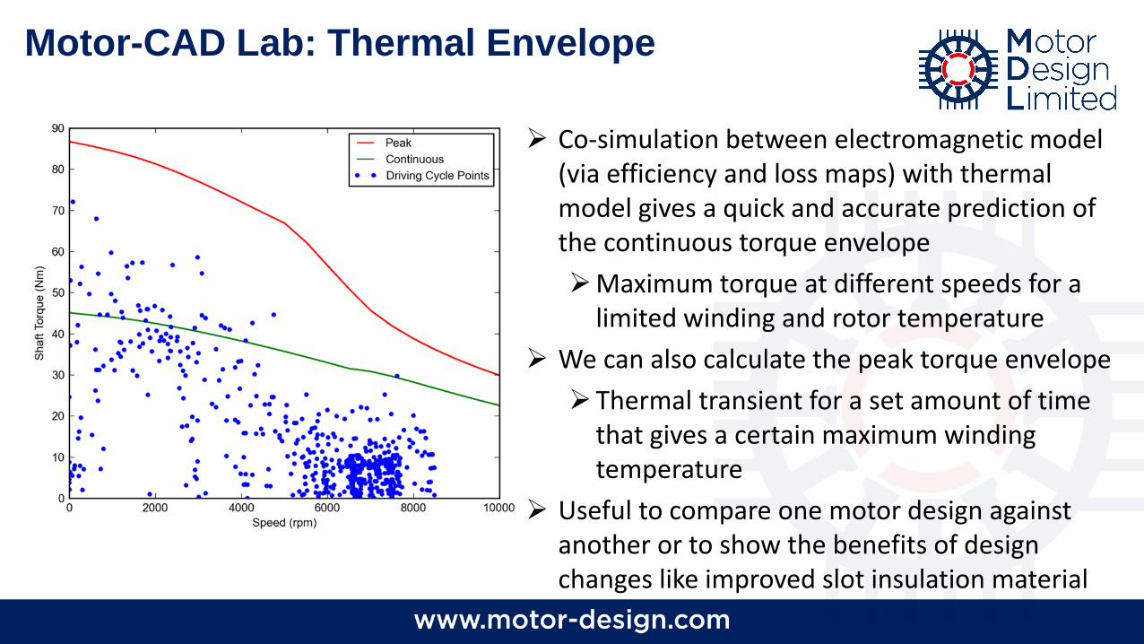
Motor-CAD Lab: Thermal Envelope
Co-simulation between electromagnetic model (via efficiency and loss maps) with thermal model gives a quick and accurate prediction of the continuous torque envelope
Maximum torque at different speeds for a limited winding and rotor temperature
We can also calculate the peak torque envelope
Thermal transient for a set amount of time that gives a certain maximum winding temperature
Useful to compare one motor design against another or to show the benefits of design changes like improved slot insulation material
16
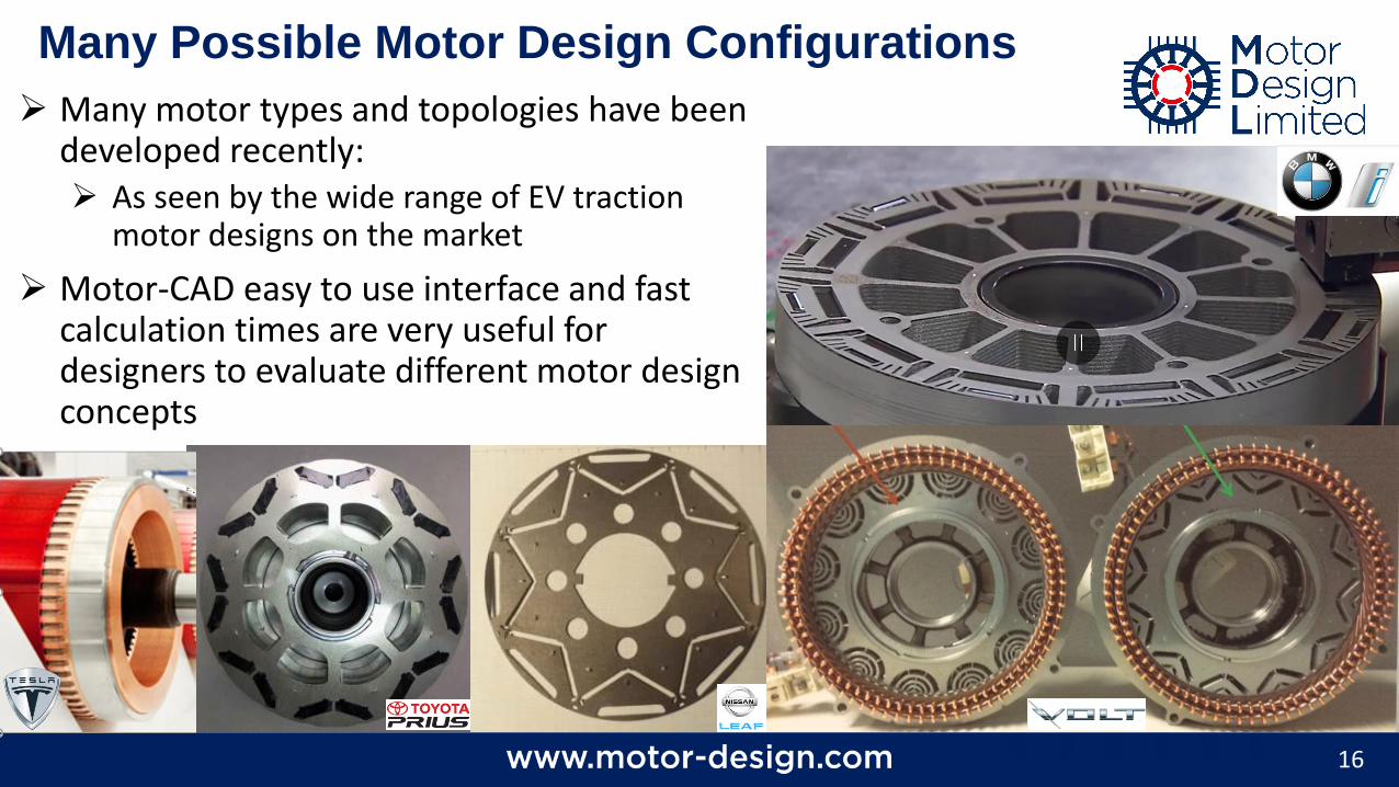
Many Possible Motor Design Configurations
Many motor types and topologies have been developed recently: As seen by the wide range of EV traction
motor designs on the market
Motor-CAD easy to use interface and fast calculation times are very useful for designers to evaluate different motor design concepts
17
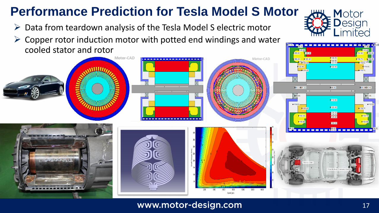
Performance Prediction for Tesla Model S Motor Data from teardown analysis of the Tesla Model S electric motor
Copper rotor induction motor with potted end windings and water cooled stator and rotor
18
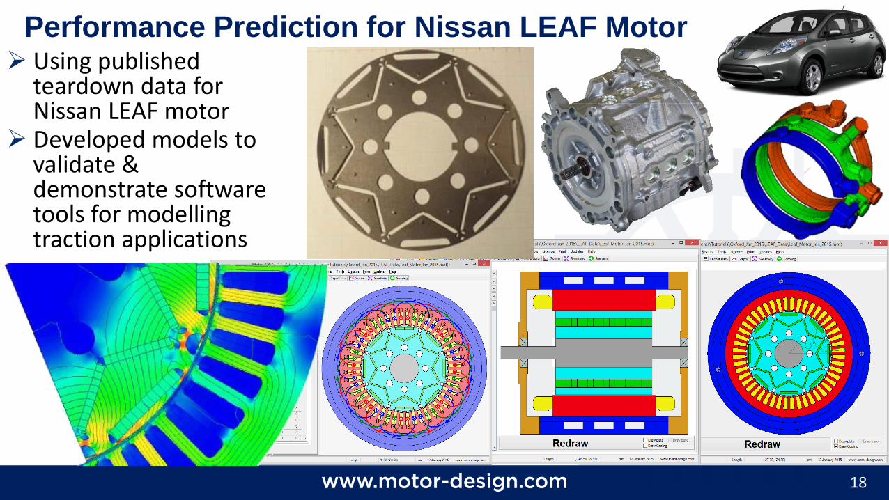
Performance Prediction for Nissan LEAF Motor Using published
teardown data for Nissan LEAF motor
Developed models to validate & demonstrate software tools for modelling traction applications
19
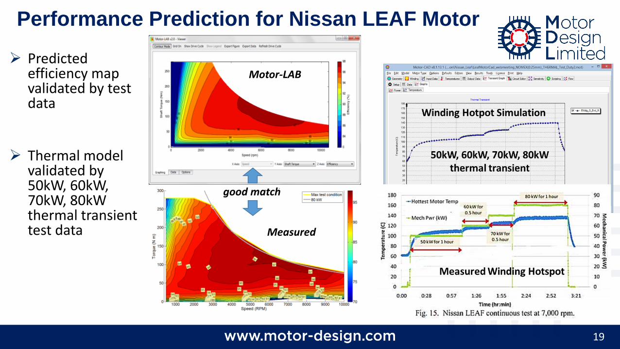
Performance Prediction for Nissan LEAF Motor
Predicted efficiency map validated by test data
Thermal model validated by 50kW, 60kW, 70kW, 80kW thermal transient test data
good match
Motor-LAB
Measured
20
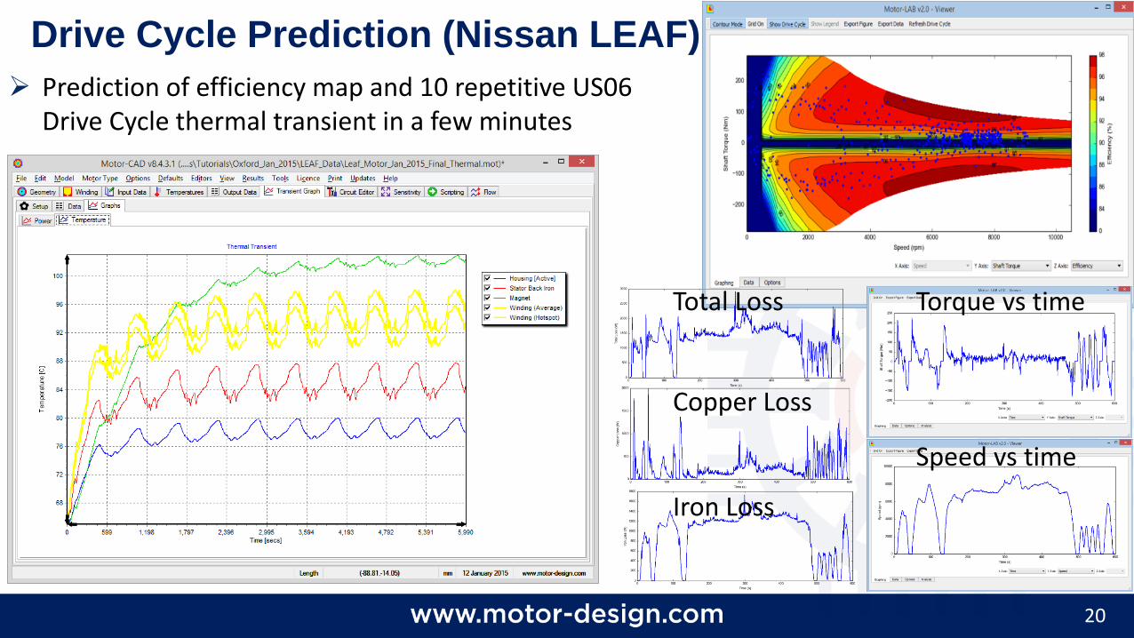
Drive Cycle Prediction (Nissan LEAF)
Prediction of efficiency map and 10 repetitive US06 Drive Cycle thermal transient in a few minutes
Torque vs time
Speed vs time
Total Loss
Copper Loss
Iron Loss
21
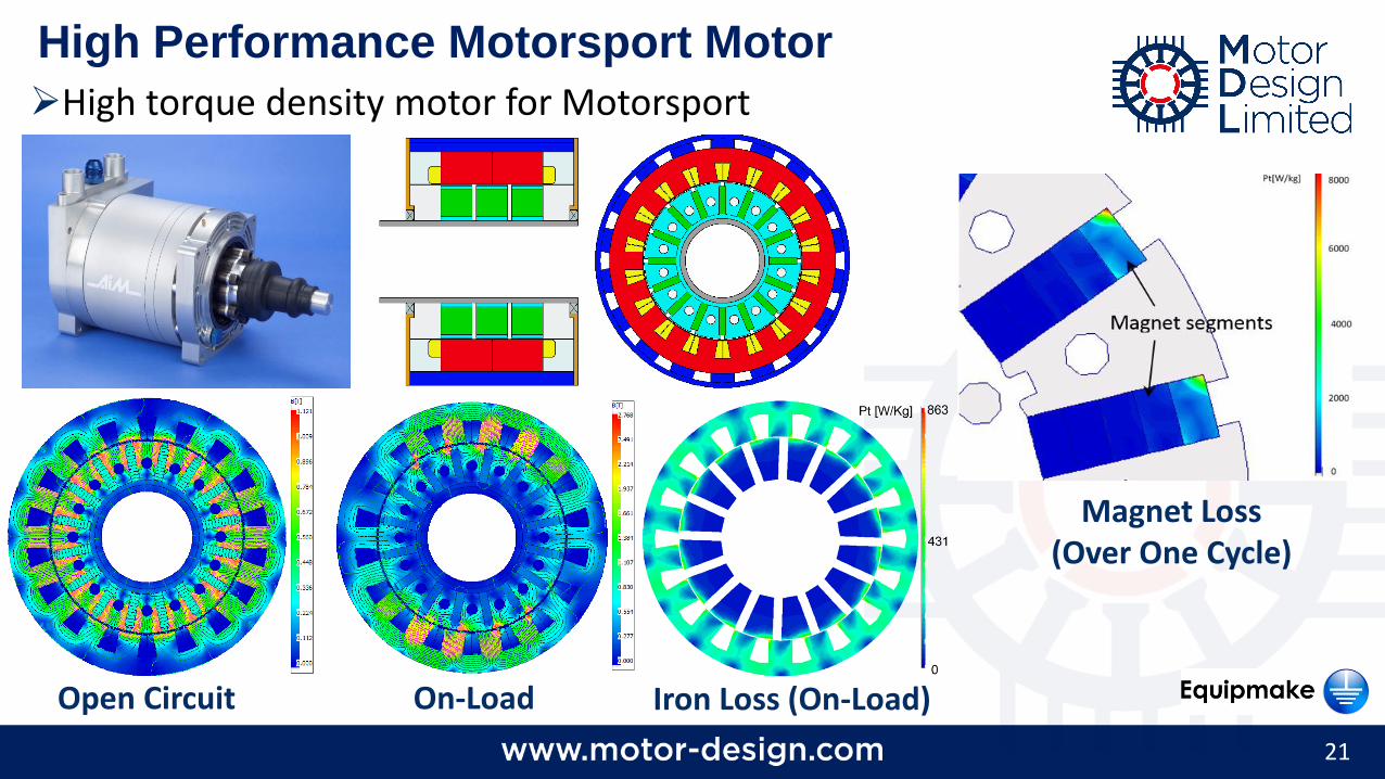
High Performance Motorsport Motor
High torque density motor for Motorsport
On-LoadOpen Circuit Iron Loss (On-Load)
Magnet Loss(Over One Cycle)
22
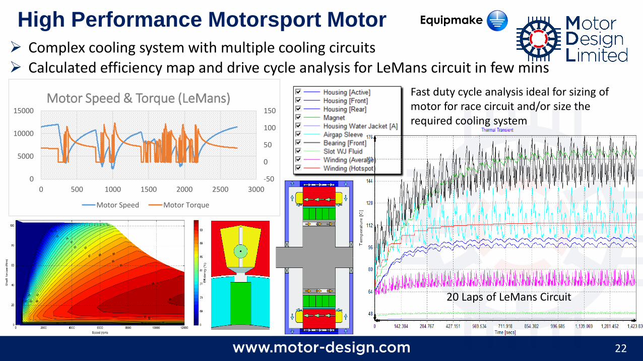
High Performance Motorsport Motor
Complex cooling system with multiple cooling circuits Calculated efficiency map and drive cycle analysis for LeMans circuit in few mins
-50
0
50
100
150
0
5000
10000
15000
0 500 1000 1500 2000 2500 3000
Motor Speed & Torque (LeMans)
Motor Speed Motor Torque
Fast duty cycle analysis ideal for sizing of motor for race circuit and/or size the required cooling system
20 Laps of LeMans Circuit
23
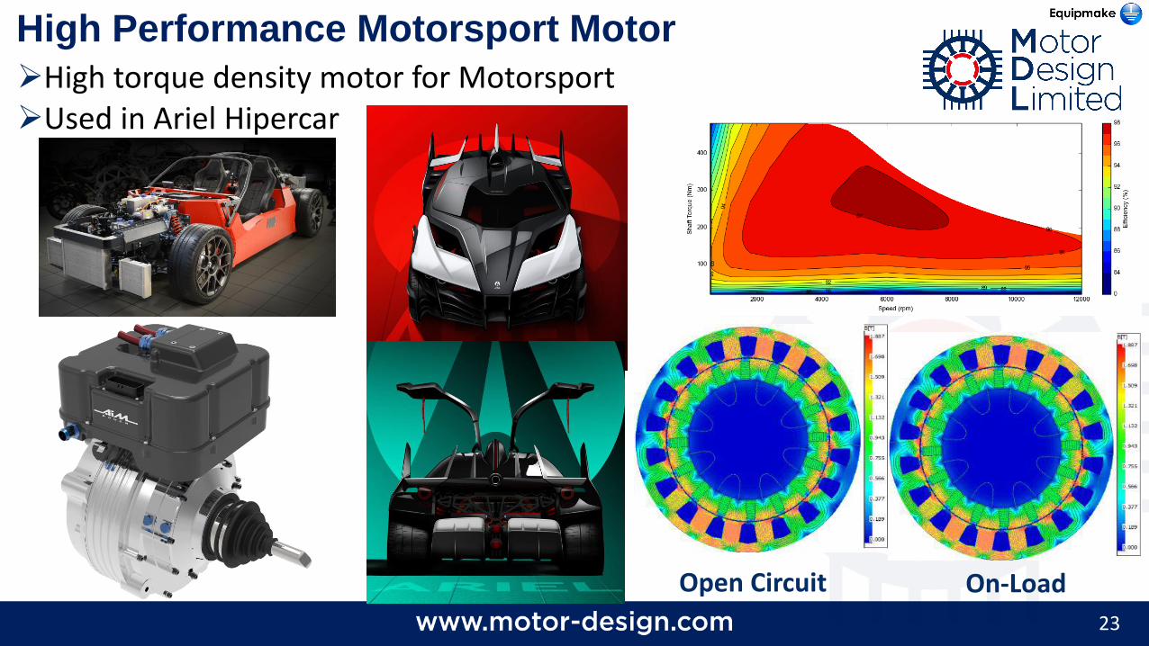
High Performance Motorsport Motor
High torque density motor for MotorsportUsed in Ariel Hipercar
On-LoadOpen Circuit
24
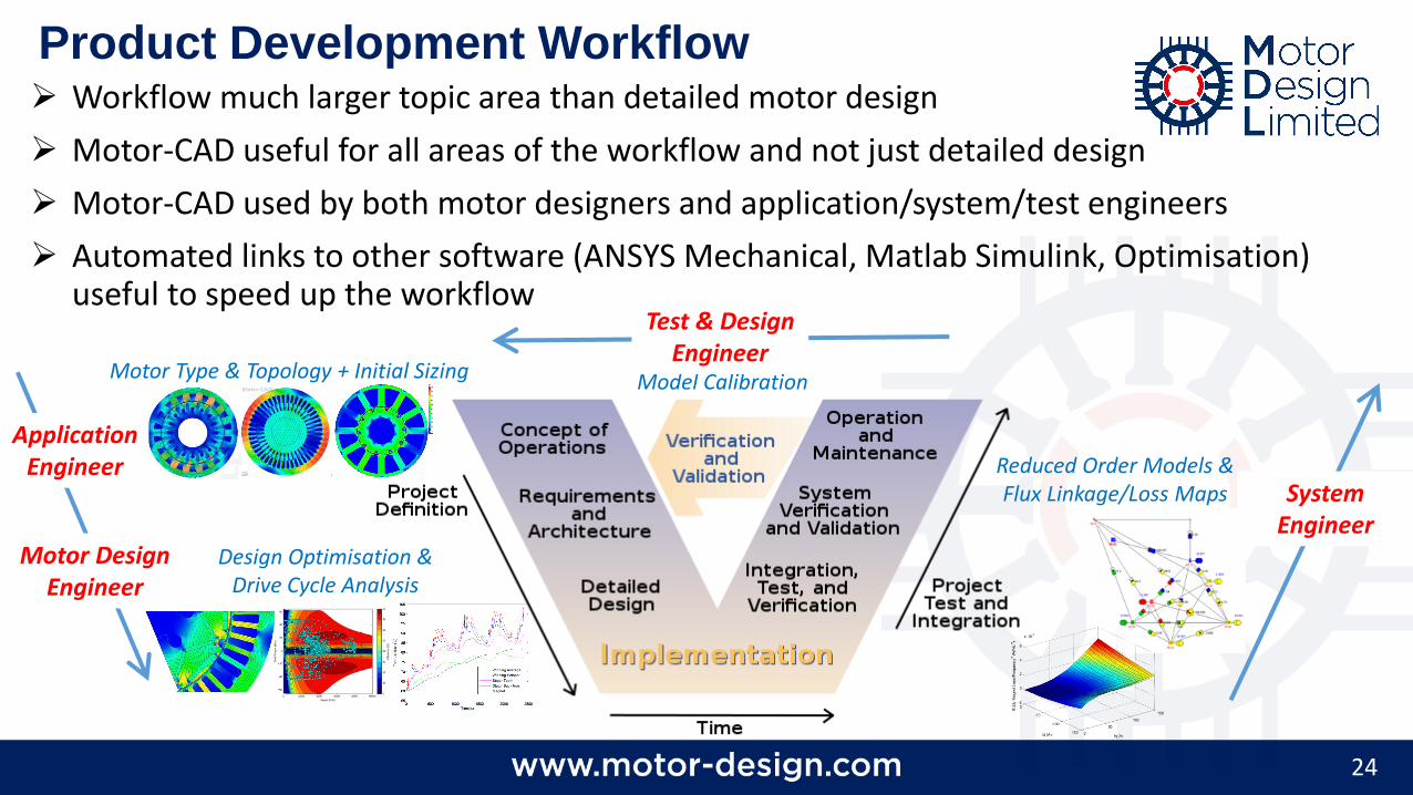
Product Development Workflow Workflow much larger topic area than detailed motor design
Motor-CAD useful for all areas of the workflow and not just detailed design
Motor-CAD used by both motor designers and application/system/test engineers
Automated links to other software (ANSYS Mechanical, Matlab Simulink, Optimisation) useful to speed up the workflow
Motor Design Engineer
Motor Type & Topology + Initial Sizing Model Calibration
Reduced Order Models & Flux Linkage/Loss Maps
Design Optimisation & Drive Cycle Analysis
System Engineer
Application Engineer
Test & Design Engineer
Motor-CAD Links to ANSYS & Dynardo Software
26
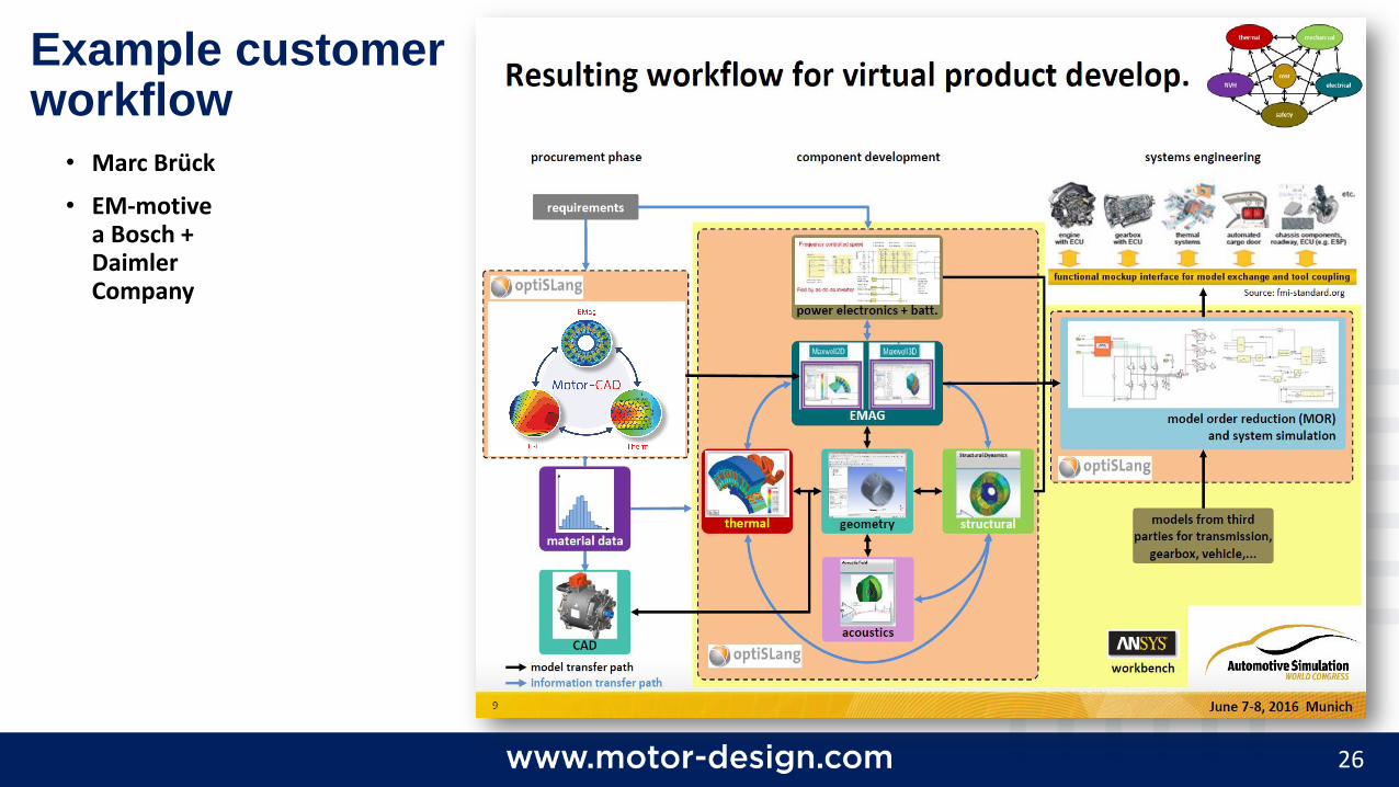
• Marc Brück
• EM-motivea Bosch + Daimler Company
Example customer workflow
27
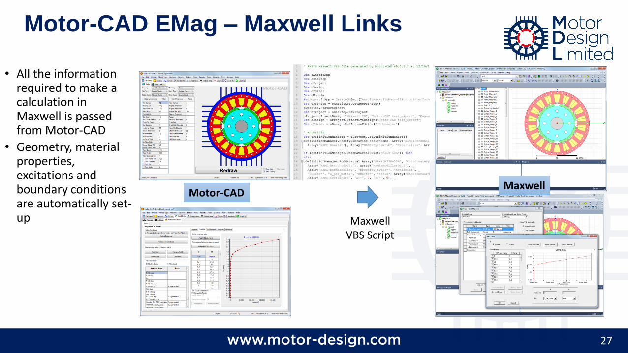
• All the information required to make a calculation in Maxwell is passed from Motor-CAD
• Geometry, material properties, excitations and boundary conditions are automatically set-up
Motor-CAD EMag – Maxwell Links
Motor-CAD
Maxwell VBS Script
Maxwell

28
• Electromagnetic data can be imported from Maxwell to create efficiency maps and calculate performance over duty cycles.
Model Created in Maxwell Maxwell Driven by Motor-LAB
Efficiency Mapin Motor-LAB &Define Duty Cycle
Duty Cycle Loss DataSent to Motor-CAD
Resulting Thermal Transientin Motor-CAD
Motor-CAD Lab: Links to Maxwell
29
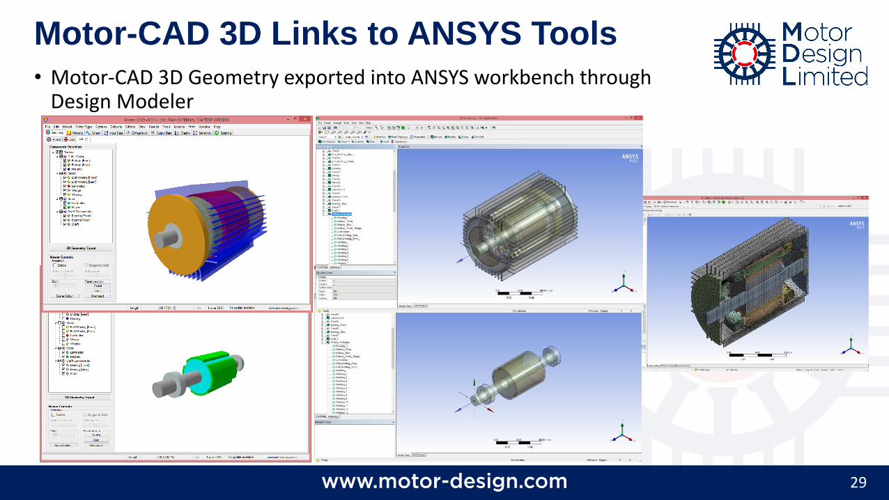
• Motor-CAD 3D Geometry exported into ANSYS workbench through Design Modeler
Motor-CAD 3D Links to ANSYS Tools
30
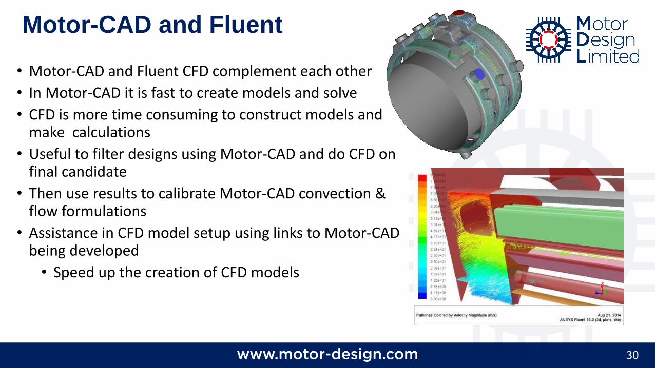
• Motor-CAD and Fluent CFD complement each other
• In Motor-CAD it is fast to create models and solve
• CFD is more time consuming to construct models and make calculations
• Useful to filter designs using Motor-CAD and do CFD on final candidate
• Then use results to calibrate Motor-CAD convection & flow formulations
• Assistance in CFD model setup using links to Motor-CAD being developed
• Speed up the creation of CFD models
Motor-CAD and Fluent
31
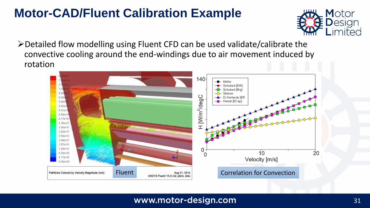
Detailed flow modelling using Fluent CFD can be used validate/calibrate the convective cooling around the end-windings due to air movement induced by rotation
Motor-CAD/Fluent Calibration Example
Fluent Correlation for Convection
32
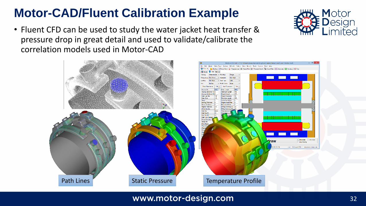
Path Lines Static Pressure
• Fluent CFD can be used to study the water jacket heat transfer & pressure drop in great detail and used to validate/calibrate the correlation models used in Motor-CAD
Motor-CAD/Fluent Calibration Example
Temperature Profile
33
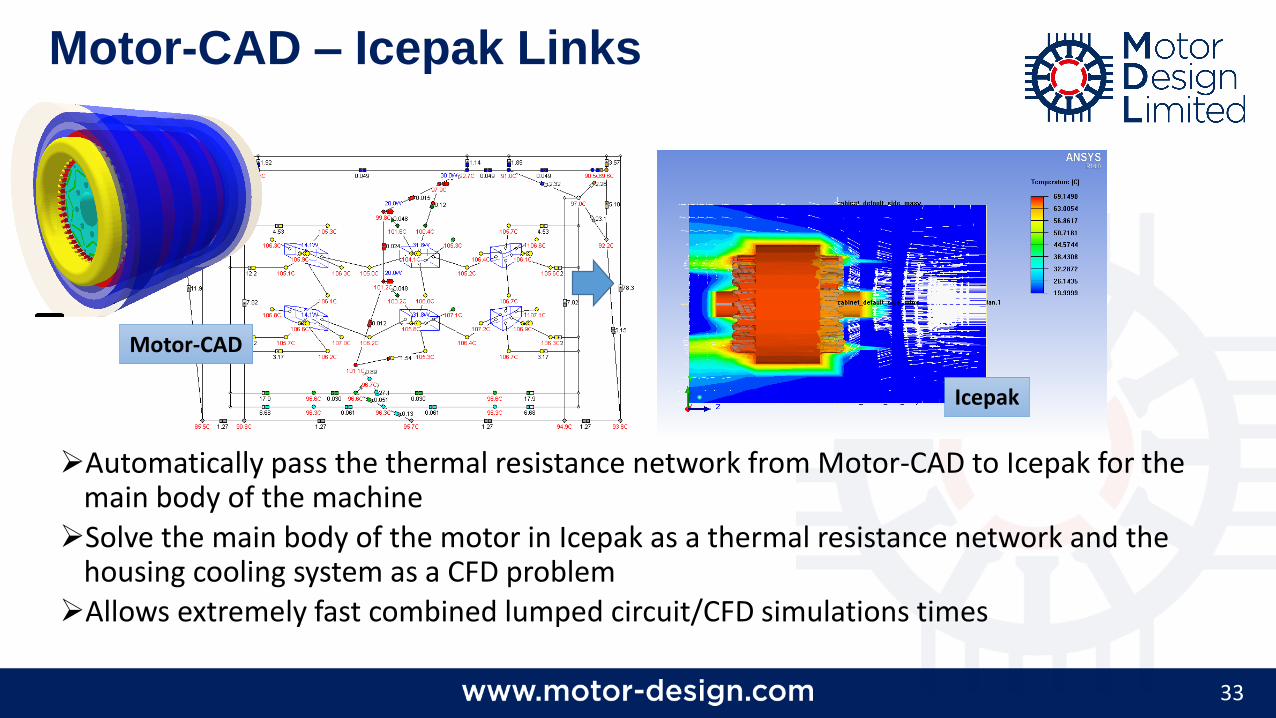
Automatically pass the thermal resistance network from Motor-CAD to Icepak for the main body of the machine
Solve the main body of the motor in Icepak as a thermal resistance network and the housing cooling system as a CFD problem
Allows extremely fast combined lumped circuit/CFD simulations times
Motor-CAD – Icepak Links
Motor-CAD
Icepak
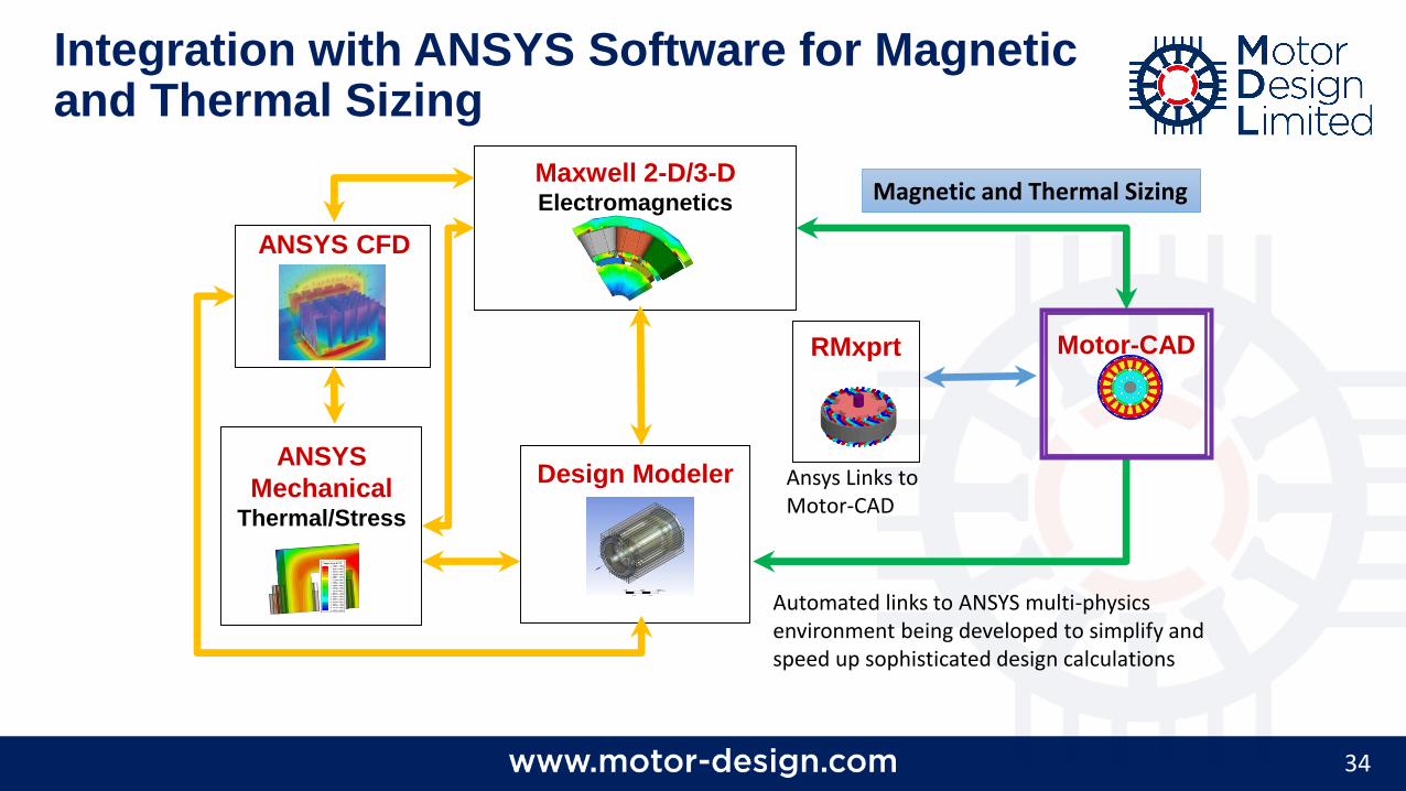
34
ANSYS
MechanicalThermal/Stress
ANSYS CFD
Maxwell 2-D/3-DElectromagnetics
Design Modeler
Motor-CAD
Automated links to ANSYS multi-physics environment being developed to simplify and speed up sophisticated design calculations
Magnetic and Thermal Sizing
Integration with ANSYS Software for Magnetic and Thermal Sizing
RMxprt
Ansys Links to Motor-CAD
35
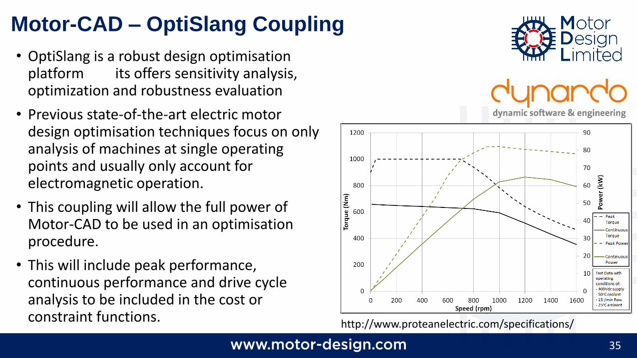
• OptiSlang is a robust design optimisation platform its offers sensitivity analysis, optimization and robustness evaluation
• Previous state-of-the-art electric motor design optimisation techniques focus on only analysis of machines at single operating points and usually only account for electromagnetic operation.
• This coupling will allow the full power of Motor-CAD to be used in an optimisation procedure.
• This will include peak performance, continuous performance and drive cycle analysis to be included in the cost or constraint functions.
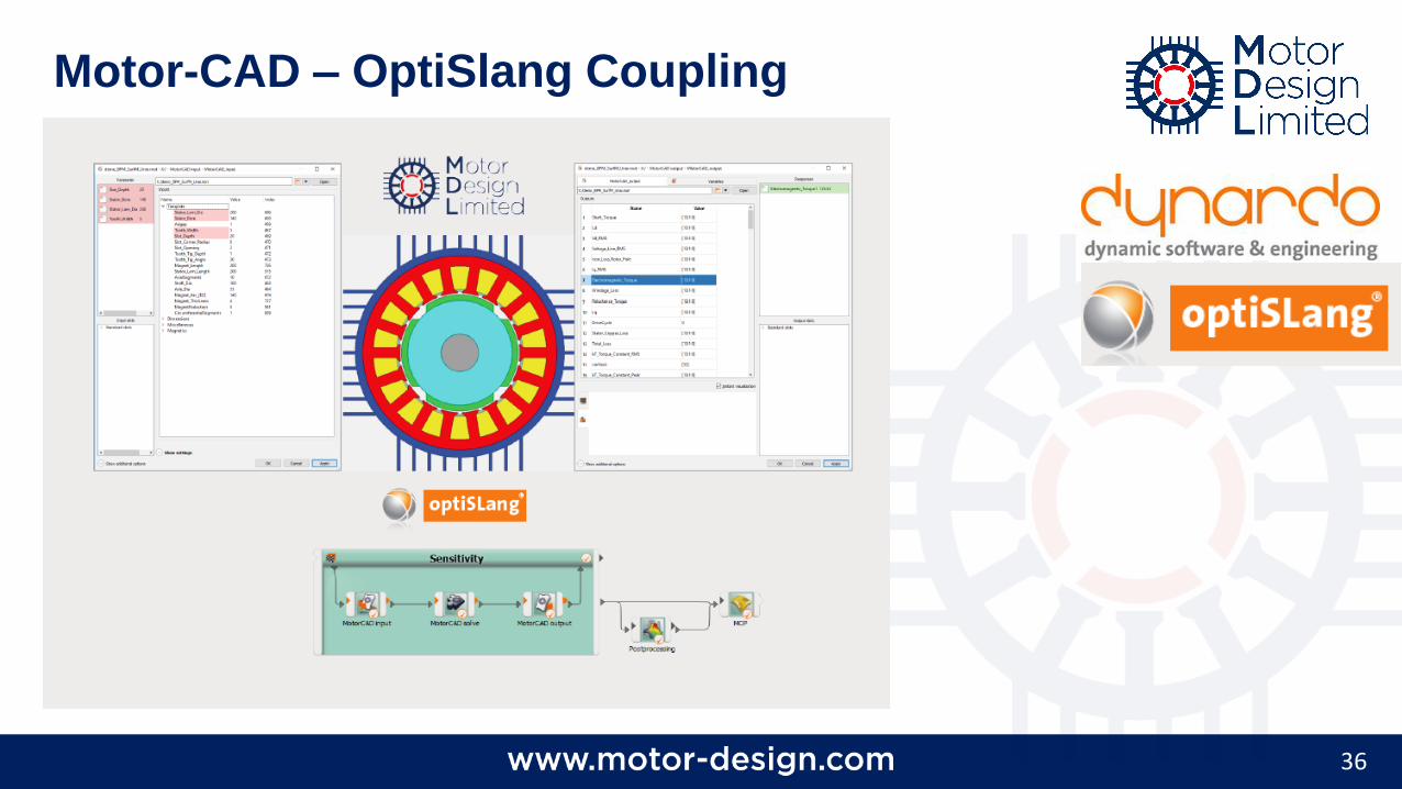
Motor-CAD – OptiSlang Coupling
http://www.proteanelectric.com/specifications/
36
Motor-CAD – OptiSlang Coupling