Multi-parameter Electricity Meter - Energy Controls Online€¦ · EM-MPO/400 Multi-parameter...
8
EM-MPO/400 Multi-parameter Electricity Meter TA201106 Issue 2, 23-Jun-2011 1 Data Sheet EM-MPO/400 Multi-parameter Electricity Meter EM-MPO/400 EM-MPO/400 I E P V RESET THD 1 2 3 4 5 6 7 8 9 10 11 12 13 14 1 2 3 4 5 6 7 8 9 10 11 12 13 14 Aux Input Volts CT1 CT2 CT3 PLS L N Ln L1 L2 L3 + - + - + - 19 20 21 22 23 24 A B O Description The EM-MPO/400 is a panel mounting 3 phase multi-parameter electricity meter with a backlit 3 line display. The /400 requires 5 A current transformers, and the /400e uses the CSENSOR range of split core current sensors. Voltage transformers may be used for medium to extra high voltage. The required transformer ratio is programmable from the panel. Used in conjunction with the EMIC (Ethernet Metering Interface Controller) or a Trend IQ3/XNC MODBUS driver, logged data can be accessed directly over the Trend network. Ideal for applications where analysis of electricity supplies is required, especially on large industrial or commercial sites. Features ▪ Multi-parameter metering ▪ Backlit LCD display ▪ /400 uses CTs (CT/.. split core range available) ▪ /400e uses current sensors (CSENSOR/.. split core sensor range available) ▪ Panel mounting ▪ RS485 MODBUS interface ▪ Interfaces to Trend system (using MODBUS driver or EMIC) ▪ Isolated pulse output available ▪ True RMS measurement to the 30th harmonic Physical Serial MODBUS voltage terminals current terminals pulse outputs 96 mm (3.78”) meter front panel cutout dimension: 92 mm (3.6”) square 83.5 mm (3.29”) 96 mm (3.78”) power input to meter view on terminals from above
Transcript of Multi-parameter Electricity Meter - Energy Controls Online€¦ · EM-MPO/400 Multi-parameter...

EM-MPO/400 Multi-parameter Electricity Meter TA201106 Issue 2, 23-Jun-2011 1
Data Sheet
EM-MPO/400Multi-parameter Electricity Meter
EM-MPO/400
EM-MPO/400
I EPVRESET THD
1 2 3 4 5 6 7 8 9 10 11 12 13 14
1 2 3 4 5 6 7 8 9 10 11 12 13 14
Aux Input Volts CT1 CT2 CT3 PLSL N Ln L1 L2 L3 + - + - + -
19 20 21 22 23 24
A B O
Description
The EM-MPO/400 is a panel mounting 3 phase multi-parameter electricity meter with a backlit 3 line display. The /400 requires 5 A current transformers, and the /400e uses the CSENSOR range of split core current sensors. Voltage transformers may be used for medium to extra high voltage. The required transformer ratio is programmable from the panel. Used in conjunction with the EMIC (Ethernet Metering Interface Controller) or a Trend IQ3/XNC MODBUS driver, logged data can be accessed directly over the Trend network.
Ideal for applications where analysis of electricity supplies is required, especially on large industrial or commercial sites.
Features
▪ Multi-parameter metering ▪ Backlit LCD display ▪ /400 uses CTs (CT/.. split core range available) ▪ /400e uses current sensors (CSENSOR/.. split core sensor range available)
▪ Panel mounting ▪ RS485 MODBUS interface ▪ Interfaces to Trend system (using MODBUS driver or EMIC) ▪ Isolated pulse output available ▪ True RMS measurement to the 30th harmonic
Physical
Serial MODBUS
voltage terminals current terminals
pulse outputs
96 mm (3.78”)
meter front panel cutout dimension: 92 mm (3.6”) square
83.5 mm (3.29”)
96 m
m (3
.78”
)
power input to meter
view on terminals from above
2 EM-MPO/400 Multi-parameter Electricity Meter TA201106 Issue 2, 23-Jun-2011
EM-MPO/400 Data Sheet
FunctiOnalitySyStEM
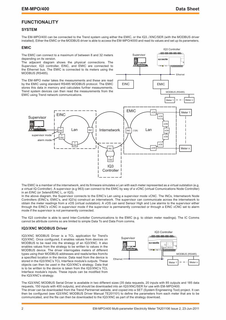
The EM-MPO/400 can be connected to the Trend system using either the EMIC, or the IQ3../XNC/SER (with the MODBUS driver installed). Either the EMIC or the MODBUS driver is able to access the EM-MPO/4000 and read its values and set up its parameters.
The EMIC is a member of the internetwork, and its firmware simulates a Lan with each meter represented as a virtual outstation (e.g. a virtual IQ Controller). A supervisor (e.g 963) can connect to the EMIC by way of a vCNC (virtual Comunications Node Controller) in an EINC (or 3xtend/EINC L, or IQ3).In the above diagram, the Supervisor connects to the EINC’s Lan using a supervisor mode vCNC. The INCs, Internetwork Node Controllers (EINC’s, EMIC’s, and IQ3’s) construct an internetwork. The supervisor can communicate across the internetwork to obtain the meter readings from a vOS (virtual outstation). A vOS can send Sensor High and Low alarms to the supervisor either through the EINC’s vCNC in supervisor mode if the supervisor is permanently connected or through a EINC vCNC set to alarm mode if the supervisor is not permanently connected.
The IQ3 controller is able to send Inter-Contoller Communications to the EMIC (e.g. to obtain meter readings). The IC Comms cannot be attribute comms so are limited to simple Data To and Data From comms.
EMIC
Supervisor
Ethernet
IQ3 Controller
EINC
Meter 1 Meter n
MODBUS (RS485)
4 5 6
2
7 8 9
3
10 11 12
4
13 14 15
5
16 17 18
6
19 20 21
7
22 23 24
8
25 26 27
9
28 29 30
10+ 0+ 0 + 0 + 0 + 0 + 0+ 0+ 0+ 0
1 2 3
1+ 0
0V
24V
24V
34 35 36
12
37 38 39
13
40 41 42
14A
31 32 33P
11
43 44 45
15
46 47 48
16100�40 V
OK RX
P 0 P 0 P 0P 0 P 0 P 0
Lan
vOS
vIQ
INC
EMIC
InternetworkINCv
CNC
EINC
Lan
Supervisor
vCNC
vCNC
supervisor mode
alarm mode
IQ3 Controller
(126)
vOS
vOS
vOS
vOS
vOS
vOS
INC
vCNC
Meter 1
Meter n
Supervisor
Ethernet
IQ3 Controller
Meter 1 Meter n
MODBUS (RS485)
4 5 6
2
7 8 9
3
10 11 12
4
13 14 15
5
16 17 18
6
19 20 21
7
22 23 24
8
25 26 27
9
28 29 30
10+ 0+ 0 + 0 + 0 + 0 + 0+ 0+ 0+ 0
1 2 3
1+ 0
0V
24V
24V
34 35 36
12
37 38 39
13
40 41 42
14A
31 32 33P
11
43 44 45
15
46 47 48
16100�40 V
OK RX
P 0 P 0 P 0P 0 P 0 P 0
TX
RX
RTS/TXEN
CTS/RXEN
RS485 RS232
iQ3/Xnc MODBuS Driver
IQ3/XNC MODBUS Driver is a TCL application for Trend’s IQ3/XNC. Once configured, it enables values from devices on MODBUS to be read into the strategy of an IQ3/XNC. It also enables values from the strategy to be written to values in the MODBUS device. The driver interrogates meters of different types using their MODBUS addresses and reads/writes from/to a specified location in the device. Data read from the device is stored in the IQ3/XNC’s TCL Interface module’s outputs. These objects can then be used in the IQ3/XNC’s strategy. Data that is to be written to the device is taken from the IQ3/XNC’s TCL Interface module’s inputs. These inputs can be modified from the IQ3/XNC’s strategy.
The IQ3/XNC MODBUS Serial Driver is available in two different sizes (35 data requests, 20 inputs with 85 outputs and 185 data requests, 150 inputs with 400 outputs), and should be downloaded into an IQ3/XNC/SER for use with EM-MPO/400.The driver can be downloaded from the Trend Partnernet website, and copied into a SET (System Engineering Tool) project. It can then be configured (see IQ3/XNC MODBUS Driver Manual TE201101) to define the parameters from each meter that are to be communicated, and the file can then be downloaded to the IQ3/XNC as part of the strategy download.
EMic
The EMIC can connect to a maximum of between 8 and 32 meters depending on its version. The adjacent diagram shows the physical connections. The Supervisor, IQ3 controller, EINC, and EMIC are connected to the Ethernet bus. The EMIC is connected to its meters using the MODBUS (RS485).
The EM-MPO meter takes the measurements and these are read by the EMIC using standard RS485 MODBUS protocol. The EMIC stores this data in memory and calculates further measurements. Trend system devices can then read the measurements from the EMIC using Trend network communications.
EM-MPO/400 Multi-parameter Electricity Meter TA201106 Issue 2, 23-Jun-2011 3
Data Sheet EM-MPO/400
HarDwarE
The EM-MPO/400 is a front panel mounting multi-parameter meter with an 3 line LCD display. It’s enclosure (DIN 4370 96 96) requires a 92 mm (3.62”) cutout and can be mounted on panels from 1 mm to 4 mm thick; 4 clips are supplied to hold the panel in place.
Power input The EM-MPO/400 requires 230 Vac, 50/60 Hz ±15%, at 5 W maximum. It can be powered from the measurement voltage but if this is subject to unusually wide variations, it may be supplied from a separate supply.
Front PanelThe front panel has an LED display on which to display the measured parameters, and to enable the unit to be configured. There are
four pushbuttons , , , and .
: This selects the current displays (Phase Amps, Peak Hold Phase Amps, Time Averaged Amps, Pk Hold Time Avge Amps)
: This selects voltage displays (Phase Volts, Line Volts, Peak Hold Phase Volts Time Averaged Volts, Pk Hold Time Avge Volts)
: This selects power displays (System active power, System Reactive power, System power, Phase Watts, System power factor, Balance current, Frequency, Phase Active powers, Phase reactive powers, Phase Power factors, Power Meab demand, Peak hold MD
: This selects energy displays (Real energy, Reactive energy, Apparent energy, Hours run, Export kWh, Export kVArh,
A combination of buttons selects power quality displays (Phase Amps THD, Phase Amps individual harmonics (2 to 15), Phase Volts THD, Phase Volts individual harmonics (2 to 15)). The buttons may be also used in combination to reset all peak values and energy registers, set up the security code, enter programing mode, fine adjust of CT/VT ratios, and pulse output test. A full description of their operation is given in the EM-MPO/400 Operating Manual, TE200116.
There are 3 LEDs: Cmd: (green) flashes when the unit receives or transmits a MODBUS communication : (green) stays on while pulse 1 output is on. : (green) stays on while pulse 2 output is on.
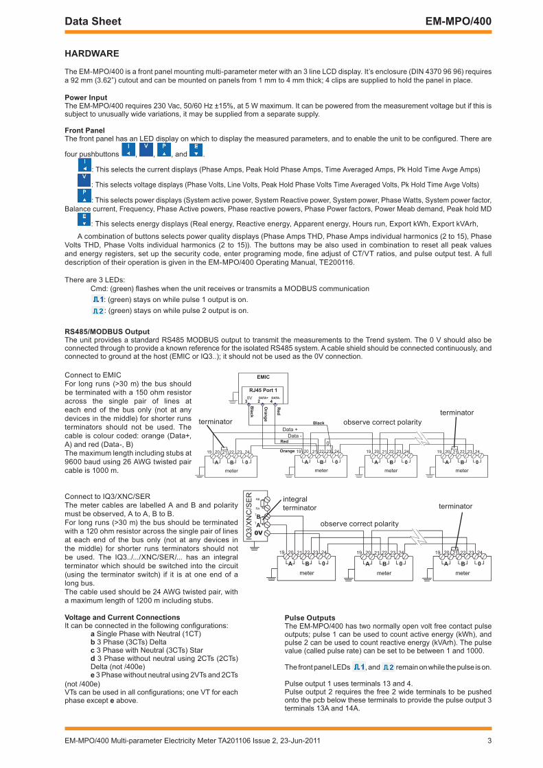
rS485/MODBuS OutputThe unit provides a standard RS485 MODBUS output to transmit the measurements to the Trend system. The 0 V should also be connected through to provide a known reference for the isolated RS485 system. A cable shield should be connected continuously, and connected to ground at the host (EMIC or IQ3..); it should not be used as the 0V connection.
0V DATA+
RJ45 Port 1
EMIC
DATA-
423
Red
Oran
ge
Red
Orange
Bla
ck
Black
0A B
meter
Data +
Data -
19 20 21 22 23 24
0A B
meter
19 20 21 22 23 24
0A B
meter
19 20 21 22 23 24
0
0A B
meter
19 20 21 22 23 24
0V
Ta
TBRA
RB
0a Bmeter
19 20 21 22 23 24
0a Bmeter
19 20 21 22 23 24
0a Bmeter
19 20 21 22 23 24
Connect to EMICFor long runs (>30 m) the bus should be terminated with a 150 ohm resistor across the single pair of lines at each end of the bus only (not at any devices in the middle) for shorter runs terminators should not be used. The cable is colour coded: orange (Data+, A) and red (Data-, B) The maximum length including stubs at 9600 baud using 26 AWG twisted pair cable is 1000 m.
terminator
terminatorintegral terminator
terminator
IQ3/
XN
C/S
ER
observe correct polarity
observe correct polarity
Pulse Outputs The EM-MPO/400 has two normally open volt free contact pulse outputs; pulse 1 can be used to count active energy (kWh), and pulse 2 can be used to count reactive energy (kVArh). The pulse value (called pulse rate) can be set to be between 1 and 1000.
The front panel LEDs , and remain on while the pulse is on.
Pulse output 1 uses terminals 13 and 4. Pulse output 2 requires the free 2 wide terminals to be pushed onto the pcb below these terminals to provide the pulse output 3 terminals 13A and 14A.
Connect to IQ3/XNC/SERThe meter cables are labelled A and B and polarity must be observed, A to A, B to B.For long runs (>30 m) the bus should be terminated with a 120 ohm resistor across the single pair of lines at each end of the bus only (not at any devices in the middle) for shorter runs terminators should not be used. The IQ3../.../XNC/SER/... has an integral terminator which should be switched into the circuit (using the terminator switch) if it is at one end of a long bus.The cable used should be 24 AWG twisted pair, with a maximum length of 1200 m including stubs.
Voltage and current connectionsIt can be connected in the following configurations:
a Single Phase with Neutral (1CT)b 3 Phase (3CTs) Deltac 3 Phase with Neutral (3CTs) Stard 3 Phase without neutral using 2CTs (2CTs) Delta (not /400e)
e 3 Phase without neutral using 2VTs and 2CTs (not /400e)VTs can be used in all configurations; one VT for each phase except e above.
4 EM-MPO/400 Multi-parameter Electricity Meter TA201106 Issue 2, 23-Jun-2011
EM-MPO/400 Data Sheet
current Sensors
The EM-MPO350 uses the CT range of split core current transformers, whereas the EM-MPO/350e uses the CSENSOR split core current sensors. A CSENSOR has an internal precision resistor connected across the secondary winding providing a safe low voltage output (0.333 Vac at CSENSOR nominal current). Due to their low voltage output CSENSORs have the advantage that the outputs can left open circuit if not connected to a meter (unlike a CT which must be short circuited). The outputs from these sensors must be wired individually direct to the meter and must not be earthed or connected to any other circuit.
FirMwarE
Parameters
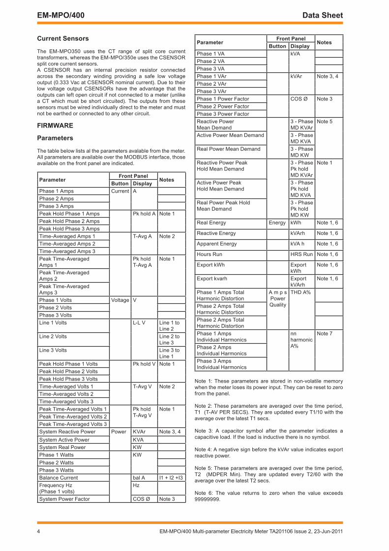
The table below lists al the parameters avalable from the meter.All parameters are available over the MODBUS interface, those available on the front panel are indicated.
ParameterFront Panel
notesButton Display
Phase 1 Amps Current APhase 2 AmpsPhase 3 AmpsPeak Hold Phase 1 Amps Pk hold A Note 1Peak Hold Phase 2 AmpsPeak Hold Phase 3 AmpsTime-Averaged Amps 1 T-Avg A Note 2Time-Averaged Amps 2Time-Averaged Amps 3Peak Time-Averaged Amps 1
Pk hold T-Avg A
Note 1
Peak Time-Averaged Amps 2Peak Time-Averaged Amps 3Phase 1 Volts Voltage VPhase 2 VoltsPhase 3 VoltsLine 1 Volts L-L V Line 1 to
Line 2Line 2 Volts Line 2 to
Line 3Line 3 Volts Line 3 to
Line 1Peak Hold Phase 1 Volts Pk hold V Note 1Peak Hold Phase 2 VoltsPeak Hold Phase 3 VoltsTime-Averaged Volts 1 T-Avg V Note 2Time-Averaged Volts 2Time-Averaged Volts 3Peak Time-Averaged Volts 1 Pk hold
T-Avg VNote 1
Peak Time-Averaged Volts 2Peak Time-Averaged Volts 3System Reactive Power Power KVAr Note 3, 4System Active Power KVASystem Real Power KWPhase 1 Watts KWPhase 2 WattsPhase 3 WattsBalance Current bal A I1 + I2 +I3Frequency Hz (Phase 1 volts)
Hz
System Power Factor COS Ø Note 3
Note 1: These parameters are stored in non-volatile memory when the meter loses its power input. They can be reset to zero from the panel.
Note 2: These parameters are averaged over the time period, T1 (T-AV PER SECS). They are updated every T1/10 with the average over the latest T1 secs.
Note 3: A capacitor symbol after the parameter indicates a capacitive load. If the load is inductive there is no symbol.
Note 4: A negative sign before the kVAr value indicates export reactive power.
Note 5: These parameters are averaged over the time period, T2 (MDPER Min). They are updated every T2/60 with the average over the latest T2 secs.
Note 6: The value returns to zero when the value exceeds 99999999.
ParameterFront Panel
notesButton Display
Phase 1 VA kVAPhase 2 VAPhase 3 VAPhase 1 VAr kVAr Note 3, 4Phase 2 VArPhase 3 VArPhase 1 Power Factor COS Ø Note 3Phase 2 Power Factor Phase 3 Power FactorReactive Power Mean Demand
3 - Phase MD KVAr
Note 5
Active Power Mean Demand 3 - Phase MD KVA
Real Power Mean Demand 3 - Phase MD KW
Reactive Power Peak Hold Mean Demand
3 - Phase Pk hold MD KVAr
Note 1
Active Power Peak Hold Mean Demand
3 - Phase Pk hold MD KVA
Real Power Peak Hold Mean Demand
3 - Phase Pk hold MD KW
Real Energy Energy kWh Note 1, 6
Reactive Energy kVArh Note 1, 6
Apparent Energy kVA h Note 1, 6
Hours Run HRS Run Note 1, 6
Export kWh Export kWh
Note 1, 6
Export kvarh Export kVArh
Note 1, 6
Phase 1 Amps Total Harmonic Distortion
A m p s PowerQuality
THD A%
Phase 2 Amps Total Harmonic DistortionPhase 2 Amps Total Harmonic DistortionPhase 1 Amps Individual Harmonics
nn harmonic A%
Note 7
Phase 2 Amps Individual HarmonicsPhase 3 Amps Individual Harmonics
EM-MPO/400 Multi-parameter Electricity Meter TA201106 Issue 2, 23-Jun-2011 5
Data Sheet EM-MPO/400
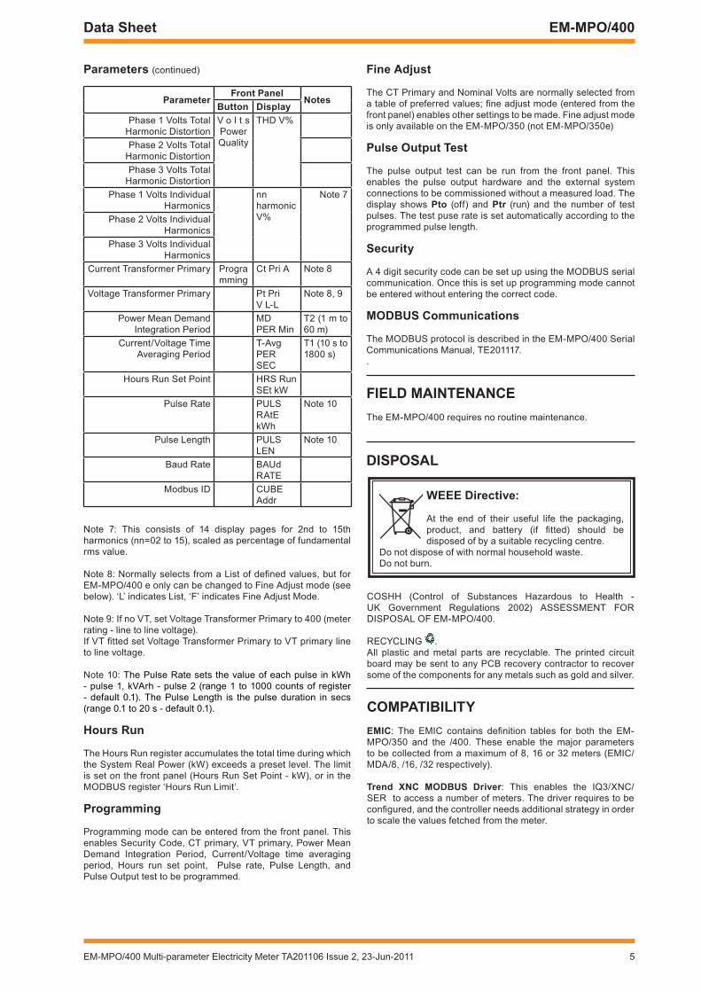
Note 7: This consists of 14 display pages for 2nd to 15th harmonics (nn=02 to 15), scaled as percentage of fundamental rms value.
Note 8: Normally selects from a List of defined values, but for EM-MPO/400 e only can be changed to Fine Adjust mode (see below). ‘L’ indicates List, ‘F’ indicates Fine Adjust Mode.
Note 9: If no VT, set Voltage Transformer Primary to 400 (meter rating - line to line voltage). If VT fitted set Voltage Transformer Primary to VT primary line to line voltage.
Note 10: The Pulse Rate sets the value of each pulse in kWh - pulse 1, kVArh - pulse 2 (range 1 to 1000 counts of register - default 0.1). The Pulse Length is the pulse duration in secs (range 0.1 to 20 s - default 0.1).
Hours run
The Hours Run register accumulates the total time during which the System Real Power (kW) exceeds a preset level. The limit is set on the front panel (Hours Run Set Point - kW), or in the MODBUS register ‘Hours Run Limit’.
Programming
Programming mode can be entered from the front panel. This enables Security Code, CT primary, VT primary, Power Mean Demand Integration Period, Current/Voltage time averaging period, Hours run set point, Pulse rate, Pulse Length, and Pulse Output test to be programmed.
Parameters (continued)
ParameterFront Panel
notesButton Display
Phase 1 Volts Total Harmonic Distortion
V o l t s PowerQuality
THD V%
Phase 2 Volts Total Harmonic DistortionPhase 3 Volts Total
Harmonic DistortionPhase 1 Volts Individual
Harmonicsnn harmonic V%
Note 7
Phase 2 Volts Individual Harmonics
Phase 3 Volts Individual Harmonics
Current Transformer Primary Programming
Ct Pri A Note 8
Voltage Transformer Primary Pt Pri V L-L
Note 8, 9
Power Mean Demand Integration Period
MDPER Min
T2 (1 m to 60 m)
Current/Voltage Time Averaging Period
T-Avg PER SEC
T1 (10 s to 1800 s)
Hours Run Set Point HRS RunSEt kW
Pulse Rate PULS RAtEkWh
Note 10
Pulse Length PULS LEN
Note 10
Baud Rate BAUd RATE
Modbus ID CUBE Addr
Fine adjust
The CT Primary and Nominal Volts are normally selected from a table of preferred values; fine adjust mode (entered from the front panel) enables other settings to be made. Fine adjust mode is only available on the EM-MPO/350 (not EM-MPO/350e)
Pulse Output test
The pulse output test can be run from the front panel. This enables the pulse output hardware and the external system connections to be commissioned without a measured load. The display shows Pto (off) and Ptr (run) and the number of test pulses. The test puse rate is set automatically according to the programmed pulse length.
Security
A 4 digit security code can be set up using the MODBUS serial communication. Once this is set up programming mode cannot be entered without entering the correct code.
MODBuS communications
The MODBUS protocol is described in the EM-MPO/400 Serial Communications Manual, TE201117..
FiElD MaintEnancEThe EM-MPO/400 requires no routine maintenance.
DiSPOSal
wEEE Directive:
At the end of their useful life the packaging, product, and battery (if fitted) should be disposed of by a suitable recycling centre.
Do not dispose of with normal household waste.Do not burn.
COSHH (Control of Substances Hazardous to Health - UK Government Regulations 2002) ASSESSMENT FOR DISPOSAL OF EM-MPO/400.
RECYCLING .All plastic and metal parts are recyclable. The printed circuit board may be sent to any PCB recovery contractor to recover some of the components for any metals such as gold and silver.
cOMPatiBilityEMic: The EMIC contains definition tables for both the EM-MPO/350 and the /400. These enable the major parameters to be collected from a maximum of 8, 16 or 32 meters (EMIC/MDA/8, /16, /32 respectively).
trend Xnc MODBuS Driver: This enables the IQ3/XNC/SER to access a number of meters. The driver requires to be configured, and the controller needs additional strategy in order to scale the values fetched from the meter.
6 EM-MPO/400 Multi-parameter Electricity Meter TA201106 Issue 2, 23-Jun-2011
EM-MPO/400 Data Sheet
1 2 3 4 5 6 7 8 9 10 11 12 13 14
1 2 3 4 5 6 7 8 9 10 11 12 13 14
Aux Input Volts CT1 CT2 CT3 PLSL N Ln L1 L2 L3 + - + - + -
19 20 21 22 23 24
A B O
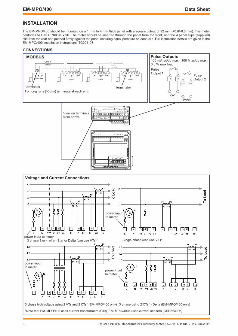
inStallatiOnThe EM-MPO/400 should be mounted on a 1 mm to 4 mm thick panel with a square cutout of 92 mm (+0.8/-0.0 mm). The meter conforms to DIN 43700 96 x 96. The meter should be inserted through the panel from the front, and the 4 panel clips (supplied) slid from the rear and pushed firmly against the panel ensuring equal pressure on each clip. Full installation details are given in the EM-MPO/400 installation instructions, TG201108.
cOnnEctiOnS
13A
13 14
14A
0a B0Va Bcontroller meter
Data +Data -
19 20 21 22 23 24
0a Bmeter
19 20 21 22 23 24
0a Bmeter
19 20 21 22 23 24
0
MODBuS Pulse Outputs
Voltage and current connections
terminator terminatorFor long runs (>30 m) terminate at each end.
100 mA ac/dc max., 100 V ac/dc max., 0.5 W max load
kWh
Pulse Output 1
Pulse Output 2
kVArh
3 phase 3 or 4 wire - Star or Delta (can use VTs)*
3 phase high voltage using 2 VTs and 2 CTs* (EM-MPO/400 only) 3 phase using 2 CTs* - Delta (EM-MPO/400 only)
Single phase (can use VT)*
*Note that EM-MPO/400 uses current transformers (CTs), EM-MPO/400e uses current sensors (CSENSORs)
power input to meter
power input to meter
power input to meter
power input to meter
View on terminals from above

EM-MPO/400 Multi-parameter Electricity Meter TA201106 Issue 2, 23-Jun-2011 7
Data Sheet EM-MPO/400
cOnnEctiOnS (continued)
current Sensors & cts
The current must pass through the CT or sensor in the correct direction (the power cable passing through the CT or sensor is the primary), and the secondary must be connected to the meter with the correct polarity (see CT Autorotation Mode above). For Trend CTs the red wire is positive and the black is negative. For CSENSORS the black wire is positive and the white (or black/white) is negative. The CT or sensor must be connected to the same phase as its associated VT.
OrDEr cODESEM-MPO/400 :Three Phase multi-parameter meter (for use with CTs)EM-MPO/400e :Three Phase multi-parameter meter (for use with current sensors)
cSEnSOr/050 :Split core current sensor, 50 A nominal current for use with EM-MPO/350e, EM-MPO/400ecSEnSOr/100 :Split core current sensor, 100 A nominal current for use with EM-MPO/350e, EM-MPO/400ecSEnSOr/150 :Split core current sensor, 150 A nominal current for use with EM-MPO/350e, EM-MPO/400ecSEnSOr/400 :Split core current sensor, 400 A nominal current for use with EM-MPO/350e, EM-MPO/400ecSEnSOr/800 :Split core current sensor, 800 A nominal current for use with EM-MPO/350e, EM-MPO/400e
The CSENSOR current sensors are described in the CSENSOR data sheet TA201118
current transformersCurrent transformers (CTs) should be ordered separately. A range of split core CTs are available from Trend as described in the Current Transformers data sheet TA102139.
S1 (+) red S2 (-) Black
Supply Load
P1 P2
CT
Current
Supply Load
S2 (-) White (Black/white)
S1 (+) Black
P1 P2
CSENSOR150A, 400A, 800A
Current
K L
S1 (+) blackS2 (-) white(black/white)
Supply Load
P1 P2
K L
CSENSOR10A, 100A
Current
8 EM-MPO/400 Multi-parameter Electricity Meter TA201106 Issue 2, 23-Jun-2011
EM-MPO/400 Data Sheet
Please send any comments about this or any other Trend technical publication to [email protected]
© 2011 Honeywell Technologies Sàrl, ECC Division. All rights reserved. Manufactured for and on behalf of the Environmental and Combustion Controls Division of Honeywell Technologies Sàrl, Z.A. La Pièce, 16, 1180 Rolle, Switzerland by its Authorized Representative.
Trend Control Systems Limited reserves the right to revise this publication from time to time and make changes to the content hereof without obligation to notify any person of such revisions or changes.
trend control Systems limitedAlbery House, Springfield Road, Horsham, West Sussex, RH12 2PQ, UK. Tel:+44 (0)1403 211888 Fax:+44 (0)1403 241608 www.trendcontrols.comtrend control System uSa6670 185th Avenue NE, Redmond, Washington 98052, USA. Tel:(425) 869-3900 Fax:(425) 869-8445 www.trendcontrols.com
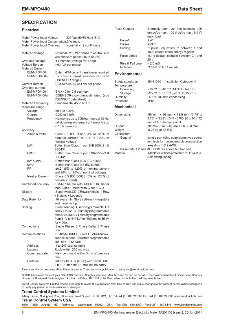
SPEciFicatiOnElectrical
Meter Power Input Voltage :230 Vac 50/60 Hz ±15 %Meter Power Input Consumption:5 W max.Meter Power Input Overload :Nominal x1.2 continuous
Metered Voltage :Nominal - 230 Vac phase to neutral, 400 Vac phase to phase (45 to 65 Hz).
Overload Voltage :4 x nominal voltage for 1 hourVoltage Burden :<0.1 VA per phaseMetered Current
EM-MPO/400 :External 5 A current transformer requiredEM-MPO/400e :External current sensors required
(CSENSOR range)Current Burden :(EM-MPO/400)<0.1 VA per phaseOverload current
EM-MPO/400 :5 A x 40 for 0.5 sec max.EM-MPO/400e :CSENSORs continuously rated (see
CSENSOR data sheet)Metered Frequency :Fundamental 45 to 65 HzMeasured range
Voltage :50% to 120%Current :0.2% to 120%Frequency :Harmonics up to 30th harmonic at 50 Hz.
Individual measurement of harmonics up to 15th harmonic
Accuracy Amps & Volts :Class 0.1 IEC 60688 (1% to 120% of
nominal current or 10% to 120% of nominal voltage)
kWh Better than Class 1 per EN62053-21 & BS8431
kVArh :Better than Class 2 per EN62053-23 & BS8431
kW & kVA :Better than Class 0.25 IEC 60688kVAr :Better than Class 0.5 IEC 60688PF :±0.2° (5% to 120% of nominal current
and 20% to 120% of nominal voltage)Neutral Current :Class 0.5 IEC 60688 (5% to 120% of
nominal current)Combined Accuracy :EM-MPO/400e with CSENSOR, better
than Class 1 meter with Class 1 CTsDisplay :Supertwist LCD. 2 Rows x 4 digits, 1 Row
x 8 digits + LegendsData Retention :10 years min. Stores all energy registers
and meter setup.Scaling :Direct reading. User-programmable CT
and VT ratios. CT primary programmable from 5 A to 25 kA. VT primary programmable from 11 V to 440 kV for /400 and to 55 kV for /400e.
Connections :Single Phase, 3 Phase Delta, 3 Phase Star.
Communications :RS485 MODBUS, 2 wire + 0 V half duplex, quarter unit load. Baud rate programmable 4k8, 9k6 19k2 baud.
Address :1 to 247 user settableLatency Reply within 250 ms max.Command rate :New command within 5 ms of previous
oneProtocol :MODBUS RTU (IEEE) with 16 bit CRC,
8 bit + 1 start bit + 1 stop bit, no parity
Pulse Outputs :Normally open, volt free contacts. 100 mA ac/dc max., 100 V ac/dc max., 0.5 W max. load
Pulse1 :kWhPulse2 :kVArhScaling :1 pulse equivalent to between 1 and
1000 counts of the energy registerPulse period :0.1 s default; settable between 0.1 and
20 sRise & Fall time :<2.0 mSIsolation :2.5 kV 50 Hz 1 minute
Environmental
Safety standards :EN61010-1 Installation Category IIITemperature
Operating :-10 °C to +65 °C (14 °F to 149 °F)Storage :-25 °C to +70 °C (-23 °F to 158 °F)
Humidity :<75 % RH non condensingProtection :IP54
Mechanical
Dimensions :96 mm x 96 mm x 83.5 mm (3.78” x 3.78” x 3.29”) (DIN 43700 96 x 96). 72 mm (2.83”) behind panel.
Cutout :92 mm (3.62”) square +0.8, -0.0 mmWeight :0.25 kg (0.55 lbs)Connectors General :single part rising cage clamp type screw
terminals for maximum cable cross section area 4 mm2 (12 AWG).
Pulse output 2 and MODBUS :as above but two part.Material :Mablex® with fire protection to UL94-V-O.
Self extinguishing