Multi Hole Film Cooling with Integrally Woven SiC-SiC Wall Panels
9
Copyright 2005 by ASME 1 Proceedings of HT2005 2005 ASME Summer Heat Transfer Conference July 17-22, 2005, San Francisco, California, USA HT 2005-72037 Multi-hole Film Cooling with Integrally Woven SiC-SiC Ceramic Wall Panels Jayesh M Mehta TK Engineering, Cincinnati, OH. [email protected] Garry Brown and Fengquan Zhong Department Of Mechanical And Aerospace Engineering, Princeton University, Princeton Dale Shouse and Craig Neuroth AFRL, Dayton, OH. Dave Marshall and Brian Cox Rockwell Science Center Thousand Oaks, CA Abstract: In the paper we have focused numerically on coupled heat transfer for multi-hole cooling of an integrally woven ceramic matrix composite combustor liner numerically. In particular, through carefully planned thought experiments we propose to expand the current state-of-the-art design space for the combustor liners to include shallow film injection angles, very small diameter film holes, and a novel film injection scheme that features opposing, staggered, shallow film cooling jets. The numerical results suggest that integrally woven SiC-SiC ceramic panels featuring shallow film angles (~O (10 0 )), small hole diameter (O (0.25 mm)), and opposed film jets yield film effectivenesses that are significantly higher than the current technology - super alloy film panels. This has the potential for significant cooling air saving that can be re-introduced in the combustor dome region and result in lower NOx emissions. Key Words: Integrally Woven SiC-SiC CMC, Film Cooling, Combustors, Emissions. 1.0 Introduction: Continuous silicon carbide fiber reinforced silicon carbide matrix (SiC-SiC) composites are candidates for high temperature applications in the gas turbine industry [1]. These composites offer a variety of physical properties, such as, low coefficient of thermal expansion, low density, and resistance to thermal shock. Furthermore, they offer increased high temperature stiffness, and strength properties stemming from a variety of toughness mechanisms [2]. The high temperature potential of the integrally woven SiC – SiC CMC also leads to several other benefits in a combustor environment. For example, compared to a conventional super alloy, a CMC liner can withstand up to 1300 0 C. As a result, it requires a significantly lower fraction of total cooling air where the saved cooling air can now be re-introduced in the combustor dome to affect a leaner combustion – ensuing lower NOx emissions. In addition, the CO emissions are lower due to reduced quenching in the thinner film at the wall. Figure 1 depicts the schematic of a two-skin CMC structure that could form an annular wall of a typical gas turbine combustor. As shown in the Figure, the outer, colder skin is constructed of a conventional super alloy while the inner - hotter skin and the supporting pins are integrally woven SiC-SiC ceramic fabrics. The integrally woven struts can also be fabricated from super alloy. The details of the weaving process and associated thermal and mechanical properties can be found in Cox, Davis, Marshall, and Yang [3], or Mehta, Shouse, Holloway, Cox, and Marshall [4]. In Figure 2, we have schematically described a simplified construct of an annular combustor liner and the associated transport processes. In this design, the outer skin is attached to
-
Upload
jayesh-mehta -
Category
Engineering
-
view
90 -
download
0
Transcript of Multi Hole Film Cooling with Integrally Woven SiC-SiC Wall Panels
Copyright 2005 by ASME 1
Proceedings of HT2005 2005 ASME Summer Heat Transfer Conference
July 17-22, 2005, San Francisco, California, USA
HT 2005-72037
Multi-hole Film Cooling with Integrally Woven SiC-SiC Ceramic Wall Panels
Jayesh M Mehta TK Engineering, Cincinnati, OH.
Garry Brown and Fengquan Zhong Department Of Mechanical And Aerospace Engineering, Princeton University, Princeton
Dale Shouse and Craig Neuroth
AFRL, Dayton, OH.
Dave Marshall and Brian Cox Rockwell Science Center
Thousand Oaks, CA
Abstract: In the paper we have focused numerically on
coupled heat transfer for multi-hole cooling of an integrally woven ceramic matrix composite combustor liner numerically. In particular, through carefully planned thought experiments we propose to expand the current state-of-the-art design space for the combustor liners to include shallow film injection angles, very small diameter film holes, and a novel film injection scheme that features opposing, staggered, shallow film cooling jets. The numerical results suggest that integrally woven SiC-SiC ceramic panels featuring shallow film angles (~O (100)), small hole diameter (O (0.25 mm)), and opposed film jets yield film effectivenesses that are significantly higher than the current technology - super alloy film panels. This has the potential for significant cooling air saving that can be re-introduced in the combustor dome region and result in lower NOx emissions. Key Words:
Integrally Woven SiC-SiC CMC, Film Cooling, Combustors, Emissions.
1.0 Introduction: Continuous silicon carbide fiber reinforced silicon carbide matrix (SiC-SiC) composites are candidates for high temperature applications in the gas turbine industry [1]. These composites offer a variety of physical properties, such as, low coefficient of
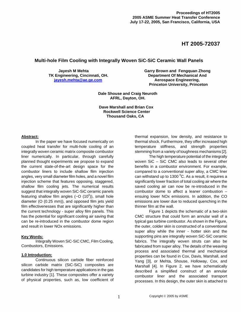
thermal expansion, low density, and resistance to thermal shock. Furthermore, they offer increased high temperature stiffness, and strength properties stemming from a variety of toughness mechanisms [2]. The high temperature potential of the integrally woven SiC – SiC CMC also leads to several other benefits in a combustor environment. For example, compared to a conventional super alloy, a CMC liner can withstand up to 1300 0C. As a result, it requires a significantly lower fraction of total cooling air where the saved cooling air can now be re-introduced in the combustor dome to affect a leaner combustion – ensuing lower NOx emissions. In addition, the CO emissions are lower due to reduced quenching in the thinner film at the wall. Figure 1 depicts the schematic of a two-skin CMC structure that could form an annular wall of a typical gas turbine combustor. As shown in the Figure, the outer, colder skin is constructed of a conventional super alloy while the inner - hotter skin and the supporting pins are integrally woven SiC-SiC ceramic fabrics. The integrally woven struts can also be fabricated from super alloy. The details of the weaving process and associated thermal and mechanical properties can be found in Cox, Davis, Marshall, and Yang [3], or Mehta, Shouse, Holloway, Cox, and Marshall [4]. In Figure 2, we have schematically described a simplified construct of an annular combustor liner and the associated transport processes. In this design, the outer skin is attached to
Copyright 2005 by ASME 2
the engine structure at the aft end, while the CMC hotter skin is suspended from it through individually spaced struts that are integrally woven with the CMC skin. As the combustor temperature increases, the outer skin grows at a rate that is different from the inner-hotter skin whereby the mismatch in the thermal growth of the two skins is absorbed by the compliant pins.
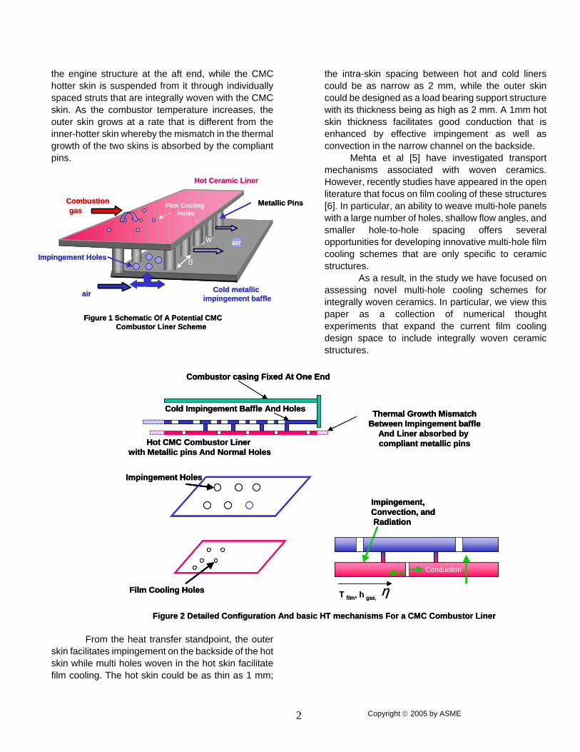
From the heat transfer standpoint, the outer skin facilitates impingement on the backside of the hot skin while multi holes woven in the hot skin facilitate film cooling. The hot skin could be as thin as 1 mm;
the intra-skin spacing between hot and cold liners could be as narrow as 2 mm, while the outer skin could be designed as a load bearing support structure with its thickness being as high as 2 mm. A 1mm hot skin thickness facilitates good conduction that is enhanced by effective impingement as well as convection in the narrow channel on the backside.
Mehta et al [5] have investigated transport mechanisms associated with woven ceramics. However, recently studies have appeared in the open literature that focus on film cooling of these structures [6]. In particular, an ability to weave multi-hole panels with a large number of holes, shallow flow angles, and smaller hole-to-hole spacing offers several opportunities for developing innovative multi-hole film cooling schemes that are only specific to ceramic structures.
As a result, in the study we have focused on assessing novel multi-hole cooling schemes for integrally woven ceramics. In particular, we view this paper as a collection of numerical thought experiments that expand the current film cooling design space to include integrally woven ceramic structures.
L
h d
w
Combustion gas
air
h
d
w
Hot Ceramic Liner
Cold metallic impingement baffle
Metallic Pins
Figure 1 Schematic Of A Potential CMCCombustor Liner Scheme
Film Cooling Holes
air
Impingement Holes
L
h d
w
Combustion gas
air
h
d
w
Hot Ceramic Liner
Cold metallic impingement baffle
Metallic Pins
Figure 1 Schematic Of A Potential CMCCombustor Liner Scheme
Film Cooling Holes
air
Impingement Holes
Conduction
Combustor casing Fixed At One End
Cold Impingement Baffle And Holes
Hot CMC Combustor Linerwith Metallic pins And Normal Holes
Film Cooling Holes
Impingement Holes
Thermal Growth MismatchBetween Impingement baffle
And Liner absorbed by compliant metallic pins
T film, h gas, η
Impingement, Convection, and Radiation
Figure 2 Detailed Configuration And basic HT mechanisms For a CMC Combustor Liner
Conduction
Combustor casing Fixed At One End
Cold Impingement Baffle And Holes
Hot CMC Combustor Linerwith Metallic pins And Normal Holes
Film Cooling Holes
Impingement Holes
Thermal Growth MismatchBetween Impingement baffle
And Liner absorbed by compliant metallic pins
T film, h gas, η
Impingement, Convection, and Radiation
Figure 2 Detailed Configuration And basic HT mechanisms For a CMC Combustor Liner
Copyright 2005 by ASME 3
Main Flow
Film Cooling Flow
Film Cooling Holes
CMC Plate
2.0 Film Cooling Research: Lin et al [7] have presented a summary of recent experimental studies in the area of adiabatic film effectiveness. Most relevant among them refer to investigations by Mayle and Camarata [8], and Sasaki et al [9] who studied angled film cooling for a turbine leading edge application. Both of them evaluated the adiabatic film effectiveness for square as well as for the staggered cooling pattern. Leger, Miron, and Emido [10], recently investigated multi-hole film cooling for a combustor liner. They concluded that hole angle inclination and hole diameter have strong influences on cooling effectiveness and cooling air consumption. In particular, they demonstrated the detrimental influence of too high a film hole angle and the film hole diameter. The film hole angle controlled the jet penetration into the boundary layer with the higher angle causing the jet to mix more readily with the hot gases. On the other hand, the larger hole diameter with the same percentage open area results in less effective film coverage. In addition to the experimental studies, various investigators have carried out numerous Computational Heat Transfer studies over the past several years. In one of the earlier studies on film, cooling Mehta and Burrus [11], and Mehta [12] had developed a simplified 2-D parabolic scheme, featuring a Low-Re Turbulence model [13]. Evidently, due to its parabolic 2-D nature, it could not handle flows with increasingly adverse pressure gradients and results featured limited accuracy. More recently, Demuren, Rodi, and Schonung [14], have performed 3-D computations with injection from a single row of holes. They considered non-isotropic turbulent viscosities and diffusivities for closure and reached good agreement with experimental data. However, Lin and Shih [15] have reported results that are more accurate. They used k-ω/SST turbulence model for the closure of the ensemble-averaged governing equations. Kumar and Mongia [16] recently evaluated two turbulence models for multi-hole cooling on gas turbine combustor liners. The first model by Sarkar and So [17], seemed to match experimental data well and the second model by Yang and Shih [18] provided less accurate comparison. With the advent of powerful microprocessors, the Direct Numerical Simulation (DNS) of the compressible Navier-Stokes equations is becoming a reality for at least low Reynolds number (Reθ < 1000) cooling systems. In one such study, Zhong and Brown [6] have investigated a film cooling system operating at
a relatively low Reθ of 620. They also coupled the heat transfer on both sides of multi-hole liner. In their coupled numerical study, turbulent mixing was modeled accurately with the DNS formulation. The mean velocity and temperature profiles matched reasonably well with their experimental data. 3.0 Uniqueness of the Present Study: The current film cooling design space is limited to either effusion cooling [18] in porous materials or film cooling with large diameter holes (> 0.5 mm), large film injection angles (>200 ), staggered pattern, large mass blowing ratios (with an associated large cooling flow requirement), and film injection in the downstream direction. In general, manufacturing processes, aerodynamic considerations or complexities associated with laser drilling of these holes impose these constraints on the current design space. With the advent of integrally woven film cooled liners we propose to expand this design space to include: smaller diameter holes (< 0.3 mm), shallower film injection angles (< 200 ), lower film jet velocities (with associated lower cooling flow requirement), and film injection that is in the upstream as well as in the downstream directions. Therefore, the thought experiments of this study present a solution space that is particularly applicable to thin, multi holed, woven ceramic liners of future advanced gas turbine combustors.
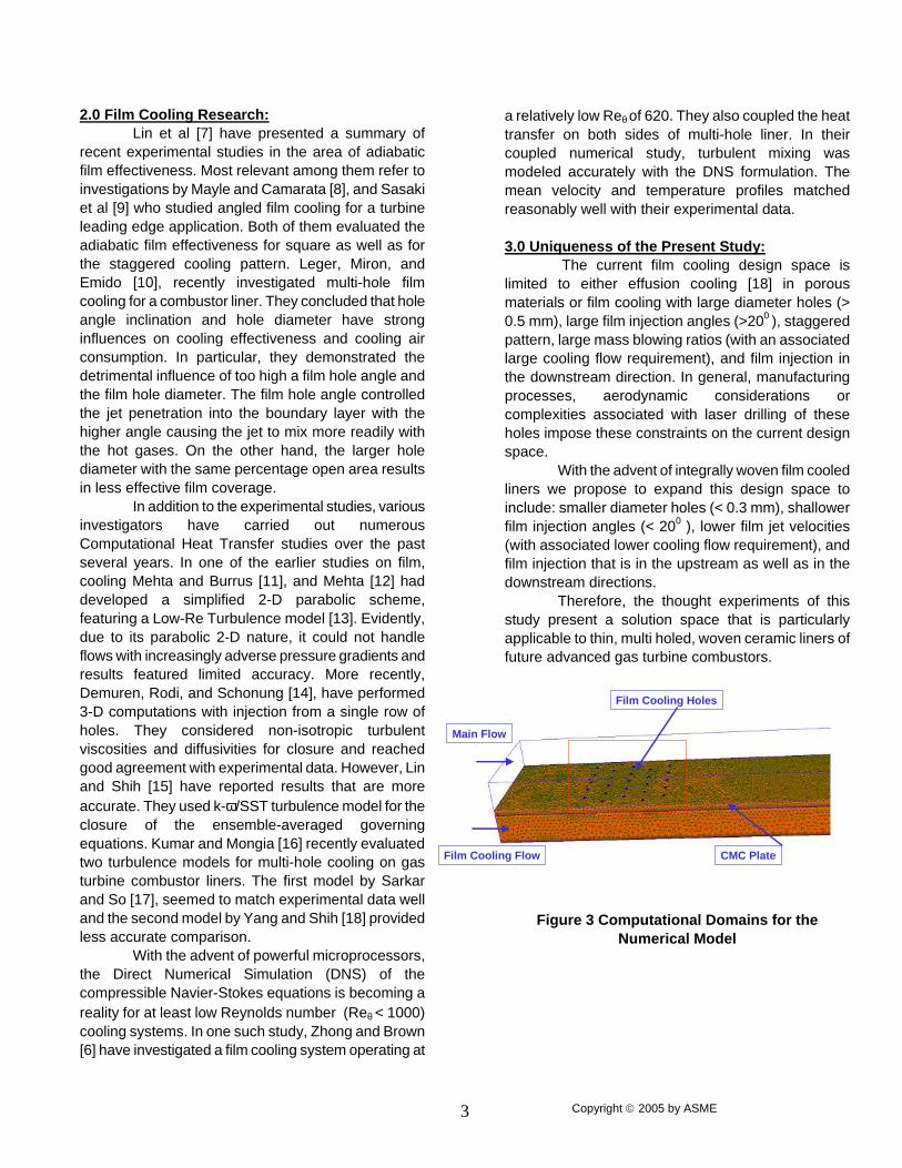
Figure 3 Computational Domains for the Numerical Model

Copyright 2005 by ASME 4
4.0 Numerical Studies: Figure 3 depicts the domain of the numerical simulations that includes the main flow channel, five rows of film cooling holes, and a plenum that feeds these holes. The inlet plane for the main flow was located 20 hole diameters upstream of the first row of holes, while the exit plane was positioned 50 hole diameters downstream from the last row of holes. The inlet and exit planes were assumed adiabatic, while periodic boundaries were assumed for the planes in the transverse directions. The Reynolds-Averaged Navier Stokes (RANS), and energy equations were discretized using a second-order upwind scheme, and they were solved using CFX - 5[19]. The pertinent turbulence model was the SMC-ω the Reynolds stress-ω model, while the low-Re scalable wall-function [19] provided the near-wall treatment. 4.1 Film Cooling Model Anchoring:
With the objective of anchoring the above model for inlet velocity, turbulence, and grid parameters, we had carried out numerical studies for the test conditions of Leger, Miron, and Emidio [10]. In particular, the following test conditions were simulated for anchoring: Mjet = 0.52,1.26,2.10; Th/Tc = 1.04, 1.10, and 1.25 [1]. In the above, Mjet is the mass blowing ratio, while Th and Tc are the free stream temperatures of the hot and cold streams, respectively. In addition, the cooling hole diameter was 0.508 mm while the film angle was varied from 30 degrees to 150 degrees from horizontal. The film-cooling pattern featured a staggered arrangement with hole-to-hole spacing (axial as well as transverse) of six diameters. In Figure 4, we have compared the film effectiveness for three angles of injection; 300, 900 (normal), and 1500 (upstream). As shown in the Figure, the numerical predictions not only compare well with the measured effectiveness, but replicate the trends reasonably well too. For 300, and 900 injections, the effectiveness shows very little difference, if any, in the intra-multi hole zone. However, downstream of the multi-hole zone the film effectiveness drops
Figure 4 Model Comparisons with Experimental
Data of Ref [10]. sharply for normal injection, compared to 300. Moreover, for 1500 injection, the film effectiveness accumulates rapidly in the intra-multi hole zone, but then it drops off rather sharply in the downstream direction. Figure 5 depicts the variation of the film effectiveness with blowing ratio. As shown in the Figure, the numerical model replicates the effectiveness values as well as the trends reasonably well. We must point out that that the above anchoring of the model was achieved with about 1.1 million nodes. This has resulted in grid resolution (in the boundary layer) as follows: ∆x+ = 9.2, and ∆z+ = 8.7, while in the normal direction there were 16 grid lines below y+ = 15. Furthermore, for these study the inlet turbulence intensity was fixed at 6%, while the turbulence length scale was fixed at 12% of the main flow channel height.
Influence Of Hole AngleModel Anchoring w ith Ref. 10
0.62
0.66
0.7
0.74
0.78
0.82
0.86
0.9
-40 0 40 80 120 160
x (mm) - Distance From First Row Of Holes
Film
Eff
ecti
ven
ess 30 (Ref 10)
90(Ref 10)
150(Ref 10)
30(CF-X)
90(CF-X)
150(CF-X)
Copyright 2005 by ASME 5
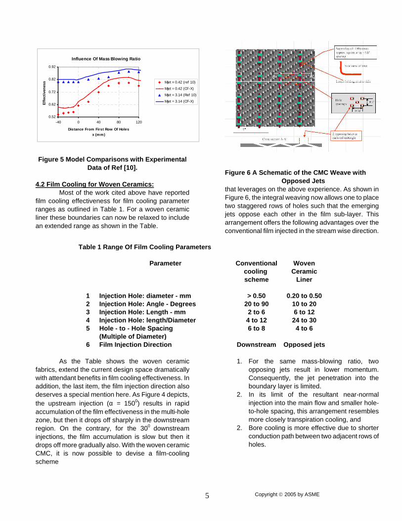
Figure 5 Model Comparisons with Experimental Data of Ref [10].
4.2 Film Cooling for Woven Ceramics: Most of the work cited above have reported film cooling effectiveness for film cooling parameter ranges as outlined in Table 1. For a woven ceramic liner these boundaries can now be relaxed to include an extended range as shown in the Table.
As the Table shows the woven ceramic
fabrics, extend the current design space dramatically with attendant benefits in film cooling effectiveness. In addition, the last item, the film injection direction also deserves a special mention here. As Figure 4 depicts, the upstream injection (α = 1500) results in rapid accumulation of the film effectiveness in the multi-hole zone, but then it drops off sharply in the downstream region. On the contrary, for the 300 downstream injections, the film accumulation is slow but then it drops off more gradually also. With the woven ceramic CMC, it is now possible to devise a film-cooling scheme
Figure 6 A Schematic of the CMC Weave with Opposed Jets that leverages on the above experience. As shown in Figure 6, the integral weaving now allows one to place two staggered rows of holes such that the emerging jets oppose each other in the film sub-layer. This arrangement offers the following advantages over the conventional film injected in the stream wise direction.
1. For the same mass-blowing ratio, two
opposing jets result in lower momentum. Consequently, the jet penetration into the boundary layer is limited.
2. In its limit of the resultant near-normal injection into the main flow and smaller hole-to-hole spacing, this arrangement resembles more closely transpiration cooling, and
2. Bore cooling is more effective due to shorter conduction path between two adjacent rows of holes.
Table 1 Range Of Film Cooling Parameters
Parameter Conventional Wovencooling Ceramicscheme Liner
1 Injection Hole: diameter - mm > 0.50 0.20 to 0.502 Injection Hole: Angle - Degrees 20 to 90 10 to 203 Injection Hole: Length - mm 2 to 6 6 to 124 Injection Hole: length/Diameter 4 to 12 24 to 305 Hole - to - Hole Spacing 6 to 8 4 to 6
(Multiple of Diameter)6 Film Injection Direction Downstream Opposed jets
Influence Of Mass Blowing Ratio
0.52
0.62
0.72
0.82
0.92
-40 0 40 80 120
Distance From First Row Of Holes x (mm)
Eff
ecti
ven
ess Mjet = 0.42 (ref 10)
Mjet = 0.42 (CF-X)
Mjet = 3.14 (Ref 10)
Mjet = 3.14 (CF-X)
Copyright 2005 by ASME 6
(b) Alpha = 90 deg
(c) Alpha = 170 deg
(a) Alpha = 10 deg
305 K 280 K 245 K
(b) Alpha = 90 deg
(c) Alpha = 170 deg
(a) Alpha = 10 deg
305 K 280 K 245 K
Influence Of Hole Angle
0.1
0.3
0.5
0.7
-40 -20 0 20 40 60 80 100
x (mm) - Distance From First Row Of Holes
Film
Eff
ecti
ven
ess
10 deg
90deg
adiabatic
170 deg
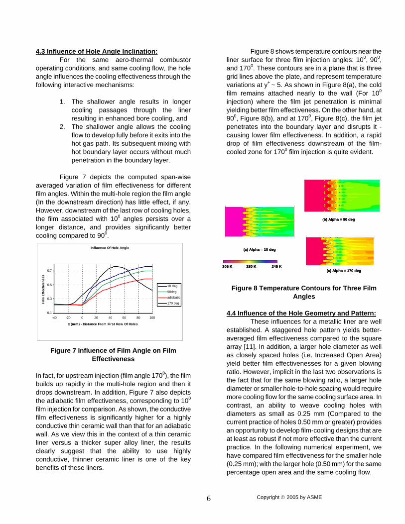
4.3 Influence of Hole Angle Inclination: For the same aero-thermal combustor operating conditions, and same cooling flow, the hole angle influences the cooling effectiveness through the following interactive mechanisms:
1. The shallower angle results in longer cooling passages through the liner resulting in enhanced bore cooling, and
2. The shallower angle allows the cooling flow to develop fully before it exits into the hot gas path. Its subsequent mixing with hot boundary layer occurs without much penetration in the boundary layer.
Figure 7 depicts the computed span-wise averaged variation of film effectiveness for different film angles. Within the multi-hole region the film angle (In the downstream direction) has little effect, if any. However, downstream of the last row of cooling holes, the film associated with 100 angles persists over a longer distance, and provides significantly better cooling compared to 900.
Figure 7 Influence of Film Angle on Film Effectiveness
In fact, for upstream injection (film angle 1700), the film builds up rapidly in the multi-hole region and then it drops downstream. In addition, Figure 7 also depicts the adiabatic film effectiveness, corresponding to 100 film injection for comparison. As shown, the conductive film effectiveness is significantly higher for a highly conductive thin ceramic wall than that for an adiabatic wall. As we view this in the context of a thin ceramic liner versus a thicker super alloy liner, the results clearly suggest that the ability to use highly conductive, thinner ceramic liner is one of the key benefits of these liners.
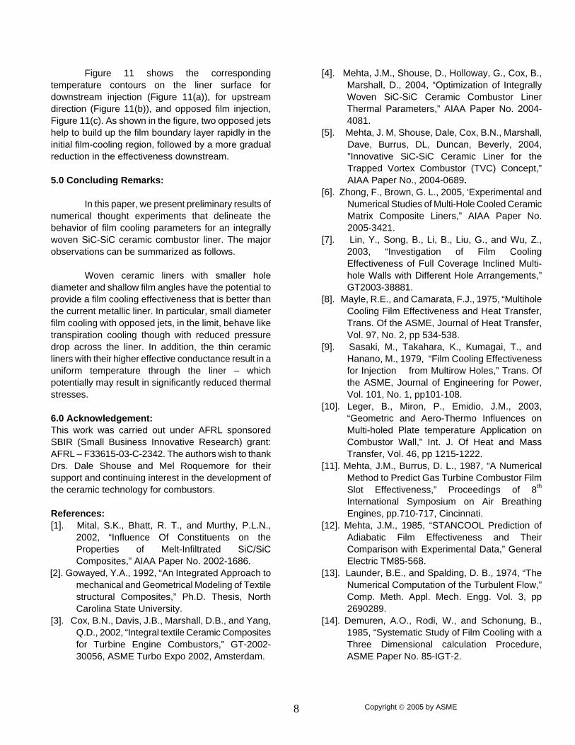
Figure 8 shows temperature contours near the liner surface for three film injection angles: 100, 900, and 1700. These contours are in a plane that is three grid lines above the plate, and represent temperature variations at y+ ~ 5. As shown in Figure 8(a), the cold film remains attached nearly to the wall (For 100 injection) where the film jet penetration is minimal yielding better film effectiveness. On the other hand, at 900, Figure 8(b), and at 1700, Figure 8(c), the film jet penetrates into the boundary layer and disrupts it - causing lower film effectiveness. In addition, a rapid drop of film effectiveness downstream of the film-cooled zone for 1700 film injection is quite evident.
Figure 8 Temperature Contours for Three Film
Angles 4.4 Influence of the Hole Geometry and Pattern: These influences for a metallic liner are well established. A staggered hole pattern yields better-averaged film effectiveness compared to the square array [11]. In addition, a larger hole diameter as well as closely spaced holes (i.e. Increased Open Area) yield better film effectivenesses for a given blowing ratio. However, implicit in the last two observations is the fact that for the same blowing ratio, a larger hole diameter or smaller hole-to-hole spacing would require more cooling flow for the same cooling surface area. In contrast, an ability to weave cooling holes with diameters as small as 0.25 mm (Compared to the current practice of holes 0.50 mm or greater) provides an opportunity to develop film-cooling designs that are at least as robust if not more effective than the current practice. In the following numerical experiment, we have compared film effectiveness for the smaller hole (0.25 mm); with the larger hole (0.50 mm) for the same percentage open area and the same cooling flow.

Copyright 2005 by ASME 7
For a non-adiabatic, ceramic liner - the cumulative result is better film cooling effectiveness which is caused by: the larger blowing ratio, and improved bore cooling. A potential drawback of such a scheme is the attendant higher-pressure drop across the liner due to high film efflux velocities, and the larger number of holes.
Figure 9 Benefit of a Ceramic liner over a conventional liner for the same cooling flow
The resulting film cooling effectiveness for a woven ceramic is compared with that for the current technology metallic liner in Figure 9. As shown, a metallic liner (with its current design parameter space, Table 1), results in film cooling effectiveness accumulating at a faster pace in the in the multi-hole region compared to the scheme with smaller holes for the ceramic liner. 4.5 Cooling with Opposed jets: The above results demonstrate that the use of integrally woven ceramics leads to a film cooling design that replicates transpiration cooling, while maintaining the benefits associated with conventional metallic film cooling. The transpiration cooling with its low hole-to-hole spacing, high blowing ratio with lower cooling flow, and high bore cooling effectiveness is probably the most effective scheme. However, it suffers from high-pressure losses for a given cooling flow. In addition, laser drilling of thousands of tiny holes in a liner is prohibitive from a cost standpoint. On the other hand, the integrally woven ceramic liners allow one to achieve some of the aerodynamic features of transpiration cooling without associated pressure and cost penalties. One such scheme is illustrated in Figure 6. As shown in the Figure, two adjacent rows are configured in a staggered manner with each row featuring jets that are opposed. Recall from Figure 7 that an upstream facing jet helps accumulate film effectiveness in the multi-
hole zone better than the downstream facing jet. In contrast, the downstream facing film persists for longer distances on the surface. In addition, the staggered nature of the scheme, the smaller diameter holes, and more effective bore cooling associated with thin, shallow angled film holes result in better cooling effectiveness.
Figure 10 Benefits Of opposed jets
Figure 10 depicts the variation of film effectiveness for a ceramic liner with opposed film cooling compared to that for the film injected into the downstream as well as upstream direction only.
Figure 11 Temperature Contours for
Downstream, Upstream, and Opposed Jets The opposed jet configuration results in the rapid accumulation of the film in the film cooled zone with very little, if any, deterioration of the film in the downstream region.
A ceramic Liner Benefit Over A Conventional metallic Liner
0.1
0.2
0.3
0.4
0.5
0.6
0.7
0.8
0.9
-40 0 40 80
x (mm) - Distance From First Row Of Holes
Film
Eff
ecti
ven
ess
Ceramic Liner
Metallic Liner
Influence Of Opposed Jets
0.1
0.3
0.5
0.7
-40 0 40 80
x (mm) - Distance From First Row Of Holes
Film
Eff
ecti
ven
ess
10 deg
Opposed
170 deg
(b) Alpha = 170 deg
(c) Alpha = 10 and 170 degOpposed
(a) Alpha = 10 deg
305 K 280 K 245 K
(b) Alpha = 170 deg
(c) Alpha = 10 and 170 degOpposed
(a) Alpha = 10 deg
305 K 280 K 245 K
Copyright 2005 by ASME 8
Figure 11 shows the corresponding temperature contours on the liner surface for downstream injection (Figure 11(a)), for upstream direction (Figure 11(b)), and opposed film injection, Figure 11(c). As shown in the figure, two opposed jets help to build up the film boundary layer rapidly in the initial film-cooling region, followed by a more gradual reduction in the effectiveness downstream. 5.0 Concluding Remarks: In this paper, we present preliminary results of numerical thought experiments that delineate the behavior of film cooling parameters for an integrally woven SiC-SiC ceramic combustor liner. The major observations can be summarized as follows. Woven ceramic liners with smaller hole diameter and shallow film angles have the potential to provide a film cooling effectiveness that is better than the current metallic liner. In particular, small diameter film cooling with opposed jets, in the limit, behave like transpiration cooling though with reduced pressure drop across the liner. In addition, the thin ceramic liners with their higher effective conductance result in a uniform temperature through the liner – which potentially may result in significantly reduced thermal stresses. 6.0 Acknowledgement: This work was carried out under AFRL sponsored SBIR (Small Business Innovative Research) grant: AFRL – F33615-03-C-2342. The authors wish to thank Drs. Dale Shouse and Mel Roquemore for their support and continuing interest in the development of the ceramic technology for combustors. References: [1]. Mital, S.K., Bhatt, R. T., and Murthy, P.L.N.,
2002, “Influence Of Constituents on the Properties of Melt-Infiltrated SiC/SiC Composites,” AIAA Paper No. 2002-1686.
[2]. Gowayed, Y.A., 1992, “An Integrated Approach to mechanical and Geometrical Modeling of Textile structural Composites,” Ph.D. Thesis, North Carolina State University.
[3]. Cox, B.N., Davis, J.B., Marshall, D.B., and Yang, Q.D., 2002, “Integral textile Ceramic Composites for Turbine Engine Combustors,” GT-2002-30056, ASME Turbo Expo 2002, Amsterdam.
[4]. Mehta, J.M., Shouse, D., Holloway, G., Cox, B., Marshall, D., 2004, “Optimization of Integrally Woven SiC-SiC Ceramic Combustor Liner Thermal Parameters,” AIAA Paper No. 2004-4081.
[5]. Mehta, J. M, Shouse, Dale, Cox, B.N., Marshall, Dave, Burrus, DL, Duncan, Beverly, 2004, ”Innovative SiC-SiC Ceramic Liner for the Trapped Vortex Combustor (TVC) Concept,” AIAA Paper No., 2004-0689.
[6]. Zhong, F., Brown, G. L., 2005, ‘Experimental and Numerical Studies of Multi-Hole Cooled Ceramic Matrix Composite Liners,” AIAA Paper No. 2005-3421.
[7]. Lin, Y., Song, B., Li, B., Liu, G., and Wu, Z., 2003, “Investigation of Film Cooling Effectiveness of Full Coverage Inclined Multi-hole Walls with Different Hole Arrangements,” GT2003-38881.
[8]. Mayle, R.E., and Camarata, F.J., 1975, “Multihole Cooling Film Effectiveness and Heat Transfer, Trans. Of the ASME, Journal of Heat Transfer, Vol. 97, No. 2, pp 534-538.
[9]. Sasaki, M., Takahara, K., Kumagai, T., and Hanano, M., 1979, “Film Cooling Effectiveness for Injection from Multirow Holes,” Trans. Of the ASME, Journal of Engineering for Power, Vol. 101, No. 1, pp101-108.
[10]. Leger, B., Miron, P., Emidio, J.M., 2003, “Geometric and Aero-Thermo Influences on Multi-holed Plate temperature Application on Combustor Wall,” Int. J. Of Heat and Mass Transfer, Vol. 46, pp 1215-1222.
[11]. Mehta, J.M., Burrus, D. L., 1987, “A Numerical Method to Predict Gas Turbine Combustor Film Slot Effectiveness,” Proceedings of 8th International Symposium on Air Breathing Engines, pp.710-717, Cincinnati.
[12]. Mehta, J.M., 1985, “STANCOOL Prediction of Adiabatic Film Effectiveness and Their Comparison with Experimental Data,” General Electric TM85-568.
[13]. Launder, B.E., and Spalding, D. B., 1974, “The Numerical Computation of the Turbulent Flow,” Comp. Meth. Appl. Mech. Engg. Vol. 3, pp 2690289.
[14]. Demuren, A.O., Rodi, W., and Schonung, B., 1985, “Systematic Study of Film Cooling with a Three Dimensional calculation Procedure, ASME Paper No. 85-IGT-2.

Copyright 2005 by ASME 9
[15]. Lin, Y., L., and Shih, T., 1998, “Computations of Discrete-Hole Film Cooling Over a Flat and Convex Surface,” ASME Paper No. 98-GT-436.
[16]. Kumar, G.N., Mongia, H.C., 2000, “Validation of Near-Turbulence Models for Film-Cooling Applications in Combustors,” AIAA 2000-0480.
[17]. Sarkar, A., and O. R., 1997, “A Critical Evaluation Of Near-Wall Two Equation Models Against
Direct Numerical Simulation Data,” Int. J. of Heat and Fluid Flow, Vol. 18, pp. 197-208.
[18]. Yang, Z., Shih, T., 1993, “New Time Scale Based k-e Model for Near Wall Turbulence,” AIAA Journal, Vol. 31, pp. 1191-1198.