Multi-functional Flow Control Valve for Water Treatment ... · Multi-functional Flow Control Valve...
41
Multi-functional Flow Control Valve for Water Treatment Systems Instruction Manual Please read this manual in details before using the valve and keep it properly in order to consult in the future. Hankscraft Runxin RevV23
Transcript of Multi-functional Flow Control Valve for Water Treatment ... · Multi-functional Flow Control Valve...

Multi-functional Flow Control Valve for
Water Treatment Systems
Instruction Manual
Please read this manual in details before using the valve and keep it properly in order to consult
in the future.
Hankscraft Runxin RevV23

Hankscraft Runxin RevV23 Valve Manual
Before the valve is put into use, please fill in the below content to refer to in the future.
Softener System Configuration (circle unit of measurement used)
Tank Size: Dia. in/mm, Height in/mm; Resin Volume ft3/L; Brine Tank Capacity L; Hardness of Raw Water grains/mmol/L; Pressure of Inlet Water psi/MPa; Control Valve Model ; Serial Number ; (13 digit number found on valve body) Specification of Drain Line Flow Control ; Injector No. ; Injector Color ; Water Source: Ground-water□ Filtered Ground-water □Tap Water □ other .
Quick conversion table 1 inch 25.4 mm 1 ft3 (of resin) 28.32 L 1 kg 2.2 lbs. 1 gal 3.79 L 1 m3/h (per hour) 4.4 gal/m (per minute) 1 gpg 17.1 mg/L or (ppm)
Parameter Set
Parameter Unit Factory Default Actual Value
Control Mode A-01/02/03/04 (Meter type) A-01 Water Treatment Capacity (Meter type) m3 200.0 Service Days (Time clock type, by days) D. 03 Regeneration Time 02:00 Settling Bed Time Min:sec 10:00 Backwash Time Min:sec 10:00 Brine & Slow Rinse Time Min:sec 60:00 Brine Refill Time Min:sec 05:00 Fast Rinse Time Min:sec 10:00 Interval Regeneration Days (Not for Time clock type) D. 30 Output Mode b-01 b-01
●If there is not a special requirement when product is purchased, the #4 drain line flow control of the Down-flow
and Up-flow softeners (Drill three holes) and #4 (blue) injector for the standard configuration (7704).
I
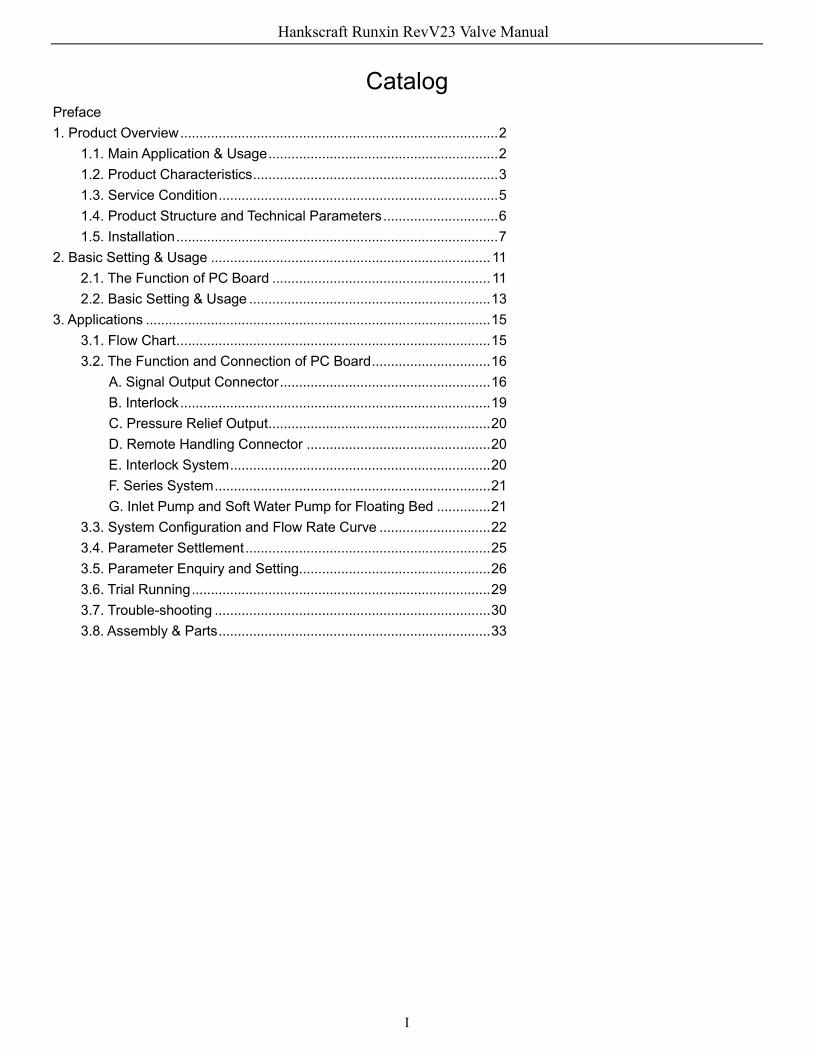
Catalog Preface 1. Product Overview ................................................................................... 2
1.1. Main Application & Usage ............................................................ 2 1.2. Product Characteristics ................................................................ 3 1.3. Service Condition ......................................................................... 5 1.4. Product Structure and Technical Parameters .............................. 6 1.5. Installation .................................................................................... 7
2. Basic Setting & Usage ......................................................................... 11 2.1. The Function of PC Board ......................................................... 11 2.2. Basic Setting & Usage ............................................................... 13
3. Applications .......................................................................................... 15 3.1. Flow Chart .................................................................................. 15 3.2. The Function and Connection of PC Board ............................... 16
A. Signal Output Connector ....................................................... 16 B. Interlock ................................................................................. 19 C. Pressure Relief Output .......................................................... 20 D. Remote Handling Connector ................................................ 20 E. Interlock System .................................................................... 20 F. Series System ........................................................................ 21 G. Inlet Pump and Soft Water Pump for Floating Bed .............. 21
3.3. System Configuration and Flow Rate Curve ............................. 22 3.4. Parameter Settlement ................................................................ 25 3.5. Parameter Enquiry and Setting.................................................. 26 3.6. Trial Running .............................................................................. 29 3.7. Trouble-shooting ........................................................................ 30 3.8. Assembly & Parts ....................................................................... 33
Hankscraft Runxin RevV23 Valve Manual

2
Preface Thank you for choosing this Hankscraft H2O Products water softening system for your water treatment needs. Please read this manual carefully before attempting to use the system for the first time, and ALWAYS adhere to all safety and operating instructions. Doing so will protect your warranty and help keep your system running and operating safely and effectively.
***Before installing, read through this manual thoroughly. Failure to use this product
within the described conditions may void the warranty***
1. Product Overview 1.1. Main Application & Usages This valve is used for softening, demineralization, or filtration of water treatment systems.
(Filtration) Suitable for swimming pool filter system. Filtration system. Activated carbon filter or sand filter of RO pretreatment system.
(Down-flow regeneration softener) (Up-flow regeneration softener) Suitable for Ion exchange equipment, with raw water hardness ≤6.5mmol/L. Boiler softening water system. RO pretreatment softening system. (Floating bed softener) Suitable for Ion exchange equipment, with raw water hardness <15mmol/L. Boiler softening water system. RO pretreatment softening system.
All plumbing and electrical work should be performed by an accredited professional to ensure all local, municipal, state, and federal guidelines are met.
Do not use the control valve with water that is unsafe or of unknown quality. This system does not sanitize or disinfect.
Do not use the brine tube, injector body, or other connectors on the RevV valve as a handle to carry the system.
Ensure there is salt in the brine tank at all times when this valve is used for softening. The brine tank should contain clean water and pellet softening salt only, at least 99.5% pure. The use of small grain or solar salt is not recommended.
When there is moderate to high turbidity, a filter should be installed before the water softening system on the inlet side.
If the water pressure exceeds 120psi, a pressure reducing valve must be installed before the water inlet. If the water pressure exceeds 80 psi, installing a pressure reducing valve before the water inlet is highly recommended. If the water pressure is under 21psi, a booster pump must be installed before the water inlet.
Replacement parts for the RevV valve should only be purchased through Hankscraft H2O Products resellers. Electrical components such as transformers are specific to the RevV valve from Hankscraft.
Regular interval monitoring of the water quality and work environment is recommended to insure proper operation of the valve and system.
Hankscraft Runxin RevV23 Valve Manual

3
1.2. Product Characteristics The advanced design incorporates a microcomputer control that analyzes real-world operating conditions and performs regeneration automatically. This unique control valve features highly polished, patented ceramic discs. The design incorporates one fixed and one moving disc, which rotates through positions to align channels creating five different fluid pathways. These five pathways, or stages, are: Service, Backwash, Brine & Slow Rinse, Brine Refill, and Fast Rinse.
Brine refill controlled by electronic ball valve. During service, electronic ball valve will trigger the brine refill. Down/Up flow softener valve can change to filter valve Manual function Regeneration can be prompted by pressing at any time. Extended power outage If there is a power outage of more than 72 hours (3 days), the time of day indicator “” will flash to remind the end user to reset the current time of day. The other set parameters will not need to be reset. The system will resume working after power is restored. LED dynamic screen display Moving (green) display bar indicates the control valve is in service, otherwise, it is in the regeneration cycle. Button lock If the display board is not in use for more than 1 minute the buttons will lock. A light indicating this will appear. Before operating again press and hold the “ ” and “ ” buttons for 5 seconds to unlock. This function can deter unintended valve operation. Program model selection Press and hold “ ” and “ ” buttons for 2 seconds, after reconnecting the power, the model will be visible on the display board, all the icons will light up, indicating access to the model setting interface. Press “ ” or “ ” to navigate to specific model, then press to save the chosen settings. Interlock function The interlock function is designed to have only one valve in regeneration, at a time, while multiple other valves are in service in a parallel valve system. In multi-step treatment systems such as RO pre-treatment, when several valves are in series, there is only one valve in regeneration or washing to ensure soft product water at all times (Figure 3-9). Signal output(Only for 63620/63520/73620/73520) There is a signal output connector on the main control board. This connector is designed to control external devices (Refer to Figure from Figure3-1 to Figure 3-8).
Hankscraft Runxin RevV23 Valve Manual

4
b-01 and b-02 output modes: b-01: a signal that is sent through the entire duration of cycles during regeneration. In this mode, the signal can be sent once per cycle; b-02 Mode: the signal is sent at the end of one cycle and at the beginning of another. In this mode, the signal is sent five times per one complete cycle.
Remote handling connector This valve has a remote handling connector. An external device which can determine when water quality is below desirable levels. When this occurs, the valve has the capability to respond to a remote signal and regenerate (Application refer to Figure3-11). Pressure relief output The valve will cut off feed water to the drain line when it switches in regeneration cycles (Same as signal output b-02). Some water treatment system, e.g. Deep Well, have a booster pump installed on the inlet to increase the system feed water pressure; this cut-off will prevent pressure on inlet from rising too quickly, potentially preventing damage to the valve. Pressure Relief Output can be used to avoid this problem. (For application refer to Figure3-10) All parameters can be modified Depending on the water quality and usage, the parameters in the system can be adjusted. Four kinds of meter type can be selected (omit for filter application)
Model Name Instruction
A-01 Meter Delayed Regeneration happens when the capacity reaches zero and the preset time of regeneration is reached.
A-02 Meter Immediate Regeneration happens when the capacity reaches zero.
A-03 Intelligent Meter Delayed
Meter Delayed Regeneration type, but by setting Resin Volume, Feed Water Hardness, Regeneration Factor, the controller will calculate the System Capacity. Regeneration mode is the same as A-01.
A-04 Intelligent Meter Immediate
Meter Immediately Regeneration Type, but by setting Resin Volume, Feed Water Hardness, Regeneration Factor, the controller will calculate the System Capacity.
A-01, A-02 only suited for filter application. Maximum day Regeneration System will automatically regenerate if water capacity was not reached in the time allotted.
Hankscraft Runxin RevV23 Valve Manual

5
1.3. Service Condition Valve should be used under the below conditions:
Items Requirement
Working conditions
Water pressure 0.2MPa~0.6MPa (29psi~87psi)
Water temperature 5℃~50℃ (41⁰F-122⁰F)
Working environment
Environment temperature 5℃~50℃ (41⁰F-122⁰F)
Relative humidity ≤ 95% (25℃) (77⁰F)
Electrical facility AC100~240V/50~60Hz
Inlet water quality
Water turbidity
Down Flow Softener < 5FTU; Up Flow Softener < 2FTU; Floating Bed < 2FTU; Filter < 20FTU
Water hardness First Grade Na+ < 6.5mmol/L; Second Grade Na+ < 10mmol/L
Free chlorine < 0.1mg/L or ppm
Iron2+ < 0.3mg/L or ppm
CODMn < 2mg/L (O2) In the above table, First Grade Na+ represents First Grade Na+ Exchanger. Second Grade Na+
represents Second Grade Na+ Exchanger. When the water turbidity exceeds the conditions, a filter should be installed on the inlet of
control valve. When the water hardness exceeds the conditions, the outlet water hardness will hardly reach
the requirement of boiler feed water (0.03 mmol/L or 0.18 gpg). It is suggested to use a second grade softener.
Hankscraft Runxin RevV23 Valve Manual

6
1.4. Product Structure and Technical Parameters A. Product dimension (The image is just for reference. It is subject to the real product).
93620 Sltucturnl drawing
63620 Structural drawing
Hankscraft Runxin RevV23 Valve Manual

7
B. Technical parameter Transformer Output: DC24V/1.5A
Model Connector Size Flow Rate m3/h
@0.2MPa (29 psi)
Remark Inlet/ Outlet
Drain Outlet
Brine Line Connector Base Riser Pipe
RevV 23-A (63620) 2″M 1.5″M 3/4″M 3/4”M 2″M 21.6
(95 gpm)
Filter, DF, or UF softeners (meter type or
time clock type) RevV 23-B
(93620) 2″M 1.5″M 3/4″M 3/4″M 2″M 20.5 (90 gpm)
Floating bed, (meter type or time clock type)
Remark: M—Male F—Female 1.5. Installation A. Installation notice
Before installation, read all instructions completely. Then obtain all materials and tools needed for installation.
The installation of system, pipes, and circuits should be accomplished by professional to ensure the product can operate normally.
Perform installation according to the relative pipeline regulations and the specification of Water Inlet, Water Outlet, Drain Outlet, and Brine Line Connector. B. Device location 1. The filter or softener should be located close to drain. 2. Ensure that the unit is installed in enough space for operating and maintenance. 3. Brine tank needs to be close to softener. 4. The unit should be kept away from heat, and should not be exposed to the elements. Sunshine or rain will cause the system damage. 5. Avoid introducing the system to Acid/Alkaline feed water or Magnetism/vibration, as they may cause the system to malfunction. 6. Do not install the filter, softener, or drain pipeline in areas where temperature may drop below 5℃, or rise above 50℃. (41F~122F) 7. Install system in a location with minimum risk of loss in case of water leaking. C. Seat frame assemble Figure 1-1 shows, 8 pieces of stands/foot mats to assemble (See the parts name for P39 “5040009 seat frame structure chart”)
Hankscraft Runxin RevV23 Valve Manual

8
D. Pipeline installation (Take RevV 23-B as a sample) 1. Install control valve and flow meter
a. Figure1-2 shows, the use of 4 pieces of hexagon bolts (M8*25) to install control valve to
the seat frame. b. Figure1-2 shows, putting the seal ring into the flow meter connector, attach water outlet;
insert the sensor into flow meter. (Omit this step when the control valve is a time clock type) c. Figure1-2 shows, when installing the brine line connector ball valve and regeneration
connector ball valve, a seal washer is needed. d. Figure1-2 shows, Insert drain line flow control into drain hose connector, then attach it to
drain outlet, and lock it. 2. Installing resin tank and top/bottom distributor
a. Fill the mineral tank, height is according to the design code. (The resin is filled up to the top window). b. Top and bottom distributor pipeline as Figure 1-3 shows. Install a manual ball vale between bottom distributor and tank.
Hankscraft Runxin RevV23 Valve Manual

9
Figure 1-3
3. Pipeline connection a. Figure1-4 shows, installation of a pressure gauge in water inlet. b. Install sampling valves to inlet, outlet, and pipeline A.B.C.D. c. Inlet pipeline should be parallel to outlet pipeline. Fasten inlet and outlet pipeline with fixed holder.
Figure1-4 Note: ●If making a soldered copper installation, do all sweat soldering before connecting pipes to the valve. Torch heat will damage plastic parts. ●When turning threaded pipe fittings onto plastic fitting, use care not to cross thread.
4. Connect brine tube and Regeneration pump tube a. Figure1-5 shows, use UPVC (DN20) to connect brine valve with brine line connector of
control valve.
Hankscraft Runxin RevV23 Valve Manual

10
Note: ● Keep brine line short and smooth. Elbow no more than four times to avoid bad brine draw.
● Brine valve must be installed.
b. Figure1-5 shows, use UPVC (DN20) to connect the outlet of regeneration pump with the regeneration connector ball valve, then connect the inlet of regeneration pump with softened water.
5. Install drain pipeline
a. Based on the table on P24, for RevV 23-B, if tank diameter is 750 mm (29.5 in), install step d. If the tank size is 900 mm (35.4 in), you need to ask supplier for the injector no. 7702 and relative DLFC. Install it as below steps indicate. b. The Injector 7701 switch to Injector 7702. c. According to matched tank diameter size, 6 drill holes on the corresponding quantity of DLFC. d. Insert drain line flow control to drain hose connector, then screw it into drain outlet, and lock it. e. Glue the drain outlet with UPVC (DN40). Put drain outlet pipe to sewer as showed in the Figure 1-6. f. For filter valve application, there is no drain line connector, install UPVC (DN50) according to step d.
Hankscraft Runxin RevV23 Valve Manual

11
Note: ● Control valve should be higher than drain outlet, and should be separated from the drain hose by at least 2 inches. ● Be sure not to connect the drain line directly to the sewer to avoid wastewater contamination.
E. Down flow softener pipeline install as shown in Figure 1-7:
Figure 1-7 2. Basic Setting & Usage 2.1. The Function of PC Board
Hankscraft Runxin RevV23 Valve Manual

12
A. Time of day indicator Light on,display the time of day. Light flashes,reminds you to reset the time of day if electrical service was interrupted
for 3 days or more (If electrical service was interrupted within 3 days, there is no need to reset the time.) B. Button lock indicator Light on, indicates the buttons are locked. At this time, pressing any single button will not work (If the display is not used for 1 minute, will light and lock the buttons.) Solution:to unlock press and hold both and for 5 seconds until the light turns off. C. Program mode indicator Light on,enter program display mode. Use or to view all values. When flashes, enter program set mode. Press or to adjust values. D. Menu/Confirm button Press , light turns on, enter program display mode and use or to view all values. In program display mode, press , will flash, enter program set mode, press or and adjust values. Press after all programs are set, a confirmation beep will sound meaning all settings are complete; returning to program display mode. E. Manual/Return button
Press in any status, it will proceed to next cycle. (Example: Press In Service status, it will start regeneration cycles instantly; Press while it is in Backwash status, it will end backwash and go to Brine & Slow Rinse). Press in program display mode, and it will return to in Service; Press in program set mode, and it will return program display mode. Press while adjusting the value, it will return to program display mode directly without saving value(s). F. Down ▼ and Up ▲ In program display mode, press ▲or ▼ to view all values. In program set mode, press ▲ or ▼ to adjust values.
Hankscraft Runxin RevV23 Valve Manual
13
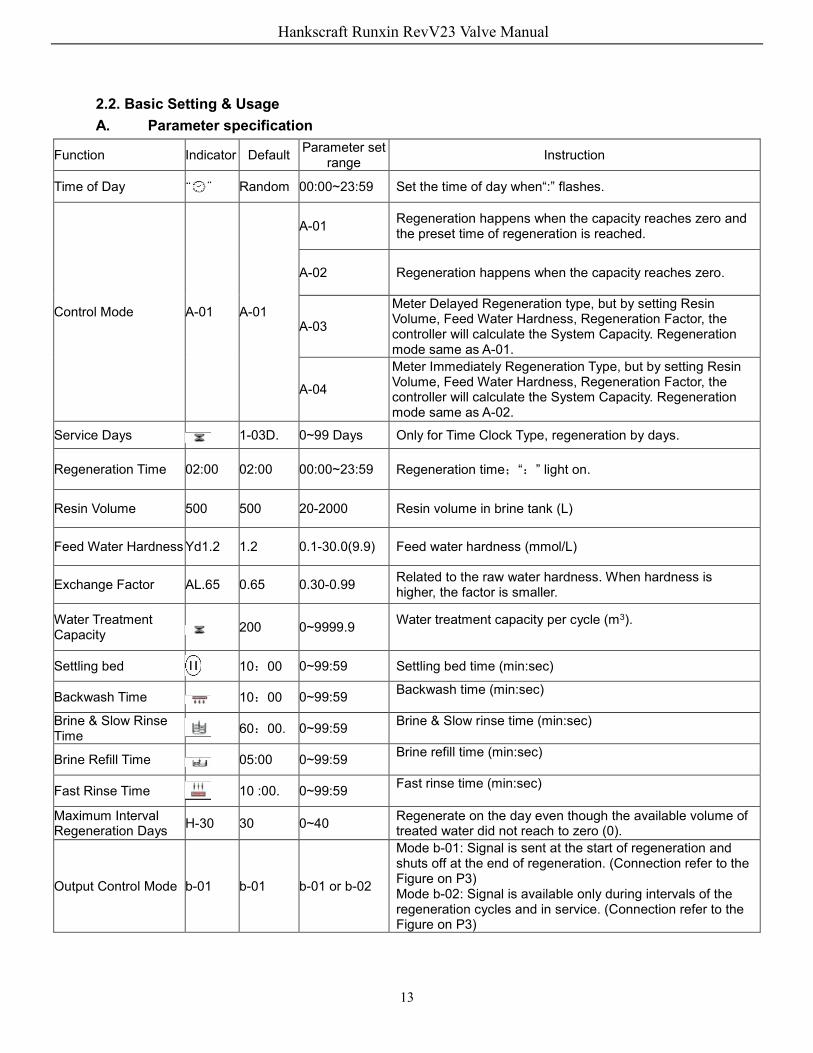
2.2. Basic Setting & Usage A. Parameter specification
Function Indicator Default Parameter set range Instruction
Time of Day Random 00:00~23:59 Set the time of day when“:” flashes.
Control Mode A-01 A-01
A-01 Regeneration happens when the capacity reaches zero and the preset time of regeneration is reached.
A-02 Regeneration happens when the capacity reaches zero.
A-03
Meter Delayed Regeneration type, but by setting Resin Volume, Feed Water Hardness, Regeneration Factor, the controller will calculate the System Capacity. Regeneration mode same as A-01.
A-04
Meter Immediately Regeneration Type, but by setting Resin Volume, Feed Water Hardness, Regeneration Factor, the controller will calculate the System Capacity. Regeneration mode same as A-02.
Service Days 1-03D. 0~99 Days Only for Time Clock Type, regeneration by days.
Regeneration Time 02:00 02:00 00:00~23:59 Regeneration time;“:” light on.
Resin Volume 500 500 20-2000 Resin volume in brine tank (L)
Feed Water Hardness Yd1.2 1.2 0.1-30.0(9.9) Feed water hardness (mmol/L)
Exchange Factor AL.65 0.65 0.30-0.99 Related to the raw water hardness. When hardness is higher, the factor is smaller.
Water Treatment Capacity 200 0~9999.9 Water treatment capacity per cycle (m3).
Settling bed 10:00 0~99:59 Settling bed time (min:sec)
Backwash Time 10:00 0~99:59 Backwash time (min:sec)
Brine & Slow Rinse Time 60:00. 0~99:59 Brine & Slow rinse time (min:sec)
Brine Refill Time 05:00 0~99:59 Brine refill time (min:sec)
Fast Rinse Time 10 :00. 0~99:59 Fast rinse time (min:sec)
Maximum Interval Regeneration Days H-30 30 0~40 Regenerate on the day even though the available volume of
treated water did not reach to zero (0).
Output Control Mode b-01 b-01 b-01 or b-02
Mode b-01: Signal is sent at the start of regeneration and shuts off at the end of regeneration. (Connection refer to the Figure on P3) Mode b-02: Signal is available only during intervals of the regeneration cycles and in service. (Connection refer to the Figure on P3)
Hankscraft Runxin RevV23 Valve Manual

14
B. Process Display (using 93620 A-01 as an example)
Illustration In Service status, the figure shows A/B/C/D; In Settling Bed status, shown in figure E/C; In
Brine& Slow Rinse status, shown in F/C; In Brine Refill status, shown in figure G/C; In Fast Rinse status, shown in figure H/C. In each status, every figure is shown for 15 seconds.
Above displays are using the Meter Type as an example. For the Time Clock Type, it shows the rest days or hours, such as 1-03D.
The display screen will only show “-00-” when the electrical motor is running. The time of day figure“” flashes continuously, such as “12:12” flashing, indicates long outage
of power. A reminder to reset the time of day. The display will show the error code, “-E1-” when the system is in error. Working process: Service→ Settling bed → Backwash→ Brine & Slow Rinse→ Brine Refill→
Fast Rinse→ Service. C. Usage
After installation is completed, parameters are set, and a test run is completed, the valve is ready to be put into use. In order to ensure the quality of outlet water, the user should complete the steps below:
① Ensure that there is solid salt at all times in the brine tank when the valve is used for softening. The brine tank should use softening salts only, 99.5% pure.
② Test the product water and raw water hardness on a regular basis. When the outlet water hardness is at an undesired level, press the button; the valve will temporary regenerate (It will not affect the original set operation cycle).
③ When the feed water hardness changes a lot, you can adjust the water treatment capacity as follow:
Press and hold both and for 5 seconds to lift the lock status. Press , and the light on, then press , the display shows the control mode. If it shows A-01or A-02, press three times, and the display will show the given water treatment capacity (If the control mode shows A-03 or A-04, then press four times, the display will show the feed water hardness); Press again, on display will flash. Press or continuously, reset the capacity value (Or water hardness). Press a confirmation beep will sound, then finish the adjustment. Press
to exit and return to service status. To estimate water treatment capacity, refer to the manufacturer’s specifications. Selecting
A-03 or A-04 intelligent control mode, the control will automatically calculate the water treatment capacity by setting resin volume, feed water hardness, and regeneration factors.
④ For A-01 or A-03 control mode (Delayed regeneration type), ensure the time is set correctly. If the time is not correct, you can adjust as follow: After lifting the lock status, press
Hankscraft Runxin RevV23 Valve Manual

15
, the and light turns on. Then press , the and hour value flash. Press or continuously, reset the hour value; Press again, and minute value flash. Press or continuously, reset the minute value; Press a confirmation beep will sound, then finish the
adjustment. Press exit and return to service status. The regeneration parameters have been set when the control valve left the factory.
Generally, it does not need to be reset.
3. Applications 3.1. Flow Chart
Hankscraft Runxin RevV23 Valve Manual

16
3.2. The Function and Connection of Circuit Board Open the front cover of the control valve, you will see the main control board and
connection ports as follows:
Functions on PC board:
Function Application Explanation
Signal output connector b-01
Outlet solenoid valve
If the system requires no hard water to flow from outlet or if controlling the liquid level in water tank.
Inlet pump Increase pressure for regeneration or washing. Use the liquid level controller to control inlet pump, ensuring there is water in tank.
Signal output connector b-02
Inlet solenoid valve or inlet pump
Used when inlet pressure is high, closes water inlet when valve is rotating to protect motor.
Pressure relief connector
Control the inlet bypass to release pressure
When valve is rotating, pressure relief connector opens to prevent pressure from increasing rapidly.
Interlock connector
To ensure only one control valve is in regeneration at a time in a system.
Used in RO Pre-treatment, water is supplied simultaneously but regenerate in turn. Also, used in second grade ion exchange equipment, etc.
Remote handling connector
Signal triggers the control to rotate to the next cycle.
It is used for on-line inspection systems, PC connections, and automatic or remote controlling valve.
A. Signal Output Connector 1) Control Solenoid Valve (Set b-01) ① Solenoid valve on outlet controls water level in brine tank. Instruction: If system strictly require no hard water flow from outlet in regeneration cycle (Mainly for no hard water flow out when valve is switching or valve in backwash or brine drawing positions), a solenoid valve could be installed on outlet, the wiring refer to Figure 3-1.
Hankscraft Runxin RevV23 Valve Manual

17
Figure 3-1 Wiring of Solenoid Valve on Outlet Function:
When valve is in service status, if soft water tank is short of water, solenoid valve is open to supply soft water, but if water tank has enough water, solenoid valve is closed, so no soft water is supplied.
When the valve in backwash status, there is no signal output. So, solenoid valve is closed, and no water flow into soft water tank.
② Solenoid valve on inlet (Set b-02)
Instruction: When inlet pressure exceeds (0.6MPa~87psi), install a solenoid valve on inlet. Control mode is b-02. Pressure relieved when valve is switching, for wiring refer to Figure 3-2. As Figure 3-3 shows, it can also use the pressure relief port to work.
Instruction:
When inlet pressure is high, install a solenoid valve on inlet to ensure the valve can switch properly. When valve is in position for Service, Backwash, Brine& Slow Rinse, Brine Refill and Fast Rinse, solenoid valve is open. When valve is switching between cycles, the solenoid valve is closed, ensuring no water can flow to the valve protecting it from damage during transition. This can prevent water bleed through or water hammering.
Use interlock cables to daisy chain valves in parallel, or series, in the same system which is suited for RO pretreatment system or second grade Na+ system. For Wiring refer to Figure 3-4:
Hankscraft Runxin RevV23 Valve Manual

18
2) Liquid Level Controller for the Inlet Pump (Two-phase motor) (Set b-01) Instruction: For a system using well or middle-tank supplying water, liquid level controller and valve, together, control pump opening or closing. For wiring refer to Figure 3-5:
Function:
When the valve is in service, if the water tank is short of water, it starts up the pump, but if the tank has enough water, the switch of liquid level controller is closed, so the pump won’t work.
When valve is in regeneration, inlet always has water no matter the condition(s) in the water tank. Valve does not pass water through the outlet in regeneration cycle, ensuring no water drains into the brine tank.
Hankscraft Runxin RevV23 Valve Manual

19
3) Liquid Level Switch in Water Tank Controls Inlet pump (Three-phase) (Set b-01)
4) Control Inlet Booster Pump (Set to b-01 or b-02) Instruction: If inlet water pressure is less than (0.2MPa~29psi), which makes drawing difficult, a booster pump is suggested to be installed on inlet. Control mode b-01. When the system is in regeneration, booster pump is open, for wiring refer to Figure 3-7. If the booster pump current is higher than 5A, system needs to have a contactor installed. For wiring refer to Figure 3-8 below.
B. Interlock Instruction:
In a parallel water treatment system, to ensure only one valve in regeneration or washing cycle and (n-1) valves in service, that is, that the function of supplying water simultaneously and regenerating individually, for wiring refer to Figure 3-9
Hankscraft Runxin RevV23 Valve Manual

20
Note: Use Interlock Cable to connect CN8 to CN7 on next valve in the loop. In a system with several valves, if the interlock cable is disconnected, the system will be
divided into two individual systems. C. Pressure Relief Output
Valve will cut off feed water to the drain line when it switches in regeneration cycles. In some water treatment system, e.g. Deep Well, one booster pump was installed on the inlet to increase the system water feed pressure. This cut-off will prevent pressure on the inlet from rising too fast, protecting the valve. Pressure Relief Output can be used to avoid this problem. For wiring refer to Figure 3-10
D. Remote Handling Connector
Online TDS meter monitors treated water rather than a flow meter, or PLC controlling the regeneration time. When the controller receives a contact closure from above instruments, regeneration begins. For wiring refers to Figure 3-11: E. Interlock System
For 2 or more valves that are interlocked, connected in one system, and when all valves are in service but regenerate individually. For wiring refer to Figure 3-12.
Hankscraft Runxin RevV23 Valve Manual

21
F. Series System This is a 2 or more valve system, all in service, with one flow meter for the entire system. For
the time type valve, the regeneration time should be set and adjusted to the Max; for the volume type valve, connect its signal output connector with the remote handle connector of the time-type valve. This provides the function of supplying water simultaneously and regenerating in order. For wiring refer to Figure 3-13:
G. Inlet pump and soft water pump connection as Figure 3-14/15/16/17 (Only for floating bed application)
Hankscraft Runxin RevV23 Valve Manual

22
3.3. System Configuration and Flow Rate Curve A. Product Configuration Softener valve for floating bed configuration with tank, resin volume, brine tank and injector.
Tank Size (in & mm)
Resin Volume (ft3 & L)
Flow Rate (m3/h)
Brine Tank Size (in & mm)
The Minimum Salt Consumption for Regeneration (lbs & Kg)
Injector Model
29.53” / 750 × 94.49” / 2400
32.7 / 925 19.9 37.8” / 960 ×
54.92” / 1395 203.93 / 92.50 7701
35.43” / 900 × 94.49” / 2400
47 / 1330 28.6 42.52” / 1080 ×
57.48” / 1460 293.22 / 133.00 7702
Note: The flow rate calculation is based on linear velocity 45m / hr; the minimum salt consumption for regeneration calculation is based on salt consumption 100g / L (Resin). Fixed bed softener valve configuration with tank, resin volume, brine tank and injector.
Tank Size (in & mm)
Resin Volume (ft3 & L)
Flow Rate (t/h)
Brine Tank Size (in & mm)
The Minimum Salt Consumption for
Regeneration (lbs & Kg)
Injector Model
35.43” / 900 × 94.49” / 2400
31.8 / 900 16.0 42.52” / 1080 ×
57.48” / 1460 297.62 / 135.00 7703
39.37” / 1000 × 94.49” / 2400
38.9 / 1100 20.0 48.82” / 1240 ×
62” / 1575 363.76 / 165.00 7704
47.24” / 1200 × 94.49” / 2400
53 / 1500 28.0 53.54” / 1360 ×
66.54” / 1690 496.04 / 225.00 7705
Note: The flow rate calculation is based on linear velocity 25m / hr; the minimum salt consumption for regeneration calculation is based on salt consumption 150g / L (Resin). Filter Valve configuration with tank, resin volume, brine tank and injector.
Tank Size (in & mm)
Filter Material (ft3 & L)
Active Carbon Filter Sand Filter
Service Flow Rate m3/L
Backwash Flow Rate m3/L
Service Flow Rate m3/L
Backwash Flow Rate
m3/L 29.53” / 750 × 70.87” / 1800
15.9 / 450 5.3 15.9 11 23.8
35.43” / 900 × 94.49” / 2400
31.8 / 900 7.6 22.9 15.9 34.3
Note: The activated carbon filter meter is based on linear velocity 12m / hr; the backwashing meter is based on intensity 10L / (m2*s); the sand filter meter is based on linear velocity 25m / hr; The backwashing meter is based on intensity 15L / (m2*s).
Hankscraft Runxin RevV23 Valve Manual

23
B. Flow Rate Characteristic 1) Pressure-flow Rate Curve Floating Bed application:
Fixed bed Softener valve:
Hankscraft Runxin RevV23 Valve Manual

24
2) Injector Parameter Table Floating Bed:
Regeneration Connector Pressure Draw Rate (gal/m & L/m)
Psi/MPa 7701 Coffee
7702 Pink
23.21/0.16 8.29/31.40 9.56/36.20 Regeneration pump parameter: Rated rate: 2 t/h; Rated lift 25m; Rated power 0.75kw; Rated speed 2850; Rated voltage 220V.
Fixed bed softener valve:
Inlet Pressure Draw Rate (gal/m & L/m) Psi/MPa 7703 Yellow 7704 Blue 7705 White
29.01/0.20 12.11/45.84 13.97/52.90 16.79/63.57 36.26/0.25 13.60/51.50 15.64/59.20 18.93/71.65 43.51/0.30 14.61/55.32 16.80/63.59 21.01/79.54 50.76/0.35 15.88/60.10 17.89/67.73 22.40/84.80 58.02/0.40 17.00/64.36 19.87/75.20 23.31/88.25
3) Configuration for Standard Injector and Drain Line Flow Control Floating Bed application:
Tank Dia. In & mm
Injector Model
Injector Color
Draw Rate Slow Rinse Brine Refill DLFC & Holes
Quantity
Fast Rinse Gal/m &
L/m Gal/m &
L/m Gal/m &
L/m t/h
29.53”/750 7701 Coffee 8.3/31.4 5.44/20.6 10.49/39.7 0 9.2
35.43”/900 7702 Pink 9.56/36.2 6.37/24.1 10.59/40.1 1 10.8 Fixed bed Softener valve:
Tank Dia. In & mm
Injector Model
Injector Color
Draw Rate Slow Rinse Brine Refill DLFC & Holes
Quantity
Backwash / Fast Rinse
Gal/m & L/m
Gal/m & L/m
Gal/m & L/m t/h
35.43”/900 7703 Yellow 14.61/55.32 9.69/36.67 20.45/77.4 1 9
39.37”/1000 7704 Blue 16.80/63.59 12.33/46.67 19.21/72.7 3 12
47.24”/1200 7705 White 21.01/79.54 13.65/51.67 21.29/80.6 6 17 Remark: The above data for the product configuration and relevant characteristics are only for reference. When put into practice, results are subject to the different requirements of raw water hardness and application.
Hankscraft Runxin RevV23 Valve Manual

25
Above parameter is tested under 0.3MPa (43.51 psi) inlet pressure. Holes quantity is the holes number on DLFC. Diameter of hole is 6, the number refer to above table. Injector 7701, 7702, 7703, 7704, 7705, corresponding part no.: 5468017, 5468018, 5468018, 5468020, 5468021. 3.4. Parameter settlement ① Service time T1 Water treatment capacity:
Q=VR×K÷YD (m3) Hardness of inlet water (mmol/L)
Exchange factor (mmol/L) 400~1000. Down-flow regeneration, take 400~750. Up-flow regeneration, take 450~1000. If the inlet water hardness is higher, the factor is smaller.
Resin volume ( m3)
By days:T1=Q+Qd (Day) Water treatment capacity per day (m3/d)
Water treatment capacity (m3)
② Backwash time T2 It is subject to the turbidity of inlet water. Generally, It is suggested to be set to 10~15
minutes. The higher the turbidity is, the longer backwash time can be set. However, if the turbidity is more than 5 FTU, it would be better to install a filter before the exchanger. ③ Brine& slow rinse time T3
T3= (40~50)×HR (min.) Generally, T3=45HR (min.)
In this formula, HR——The height of resin in exchange tank (m.) ④ Brine refill timeT4
Down-flow regeneration:T4=0.45×VR÷Brine refill speed (min.) Up-flow regeneration:T4=0.34×VR÷Brine refill speed (min.)
In this formula, VR—— Resin volume (m3) The Brine refill speed is related to inlet water pressure. It is suggested to increase by 1~2
minutes of calculated brine refilling time to make sure there is enough water in tank. (The condition is that there is a level controller installed in the brine tank) ⑤ Fast rinse time T5
T5=12×HR (min.) Generally, the water for fast rinse is 3~6 times of resin volume. It is suggested to be set
10~16 minutes, but subject to the outlet water reaching the requirement. ⑥ Exchange factor
Exchange factor =E/ (k×1000) In this formula, E——Resin working exchange capability (mmol/m3), it is related to the
quality of resin. Down-flow regeneration, take 800~900. Up-flow regeneration, take 900~1200. K——Security factor, always take 1.2~2. it is related to the hardness of inlet water: the higher the hardness is, the bigger the K is.
⑦ Regeneration time The whole cycle for generation is about two hours. Please try to set up the regeneration
time when you don’t need water according to the actual situation.
Hankscraft Runxin RevV23 Valve Manual
26
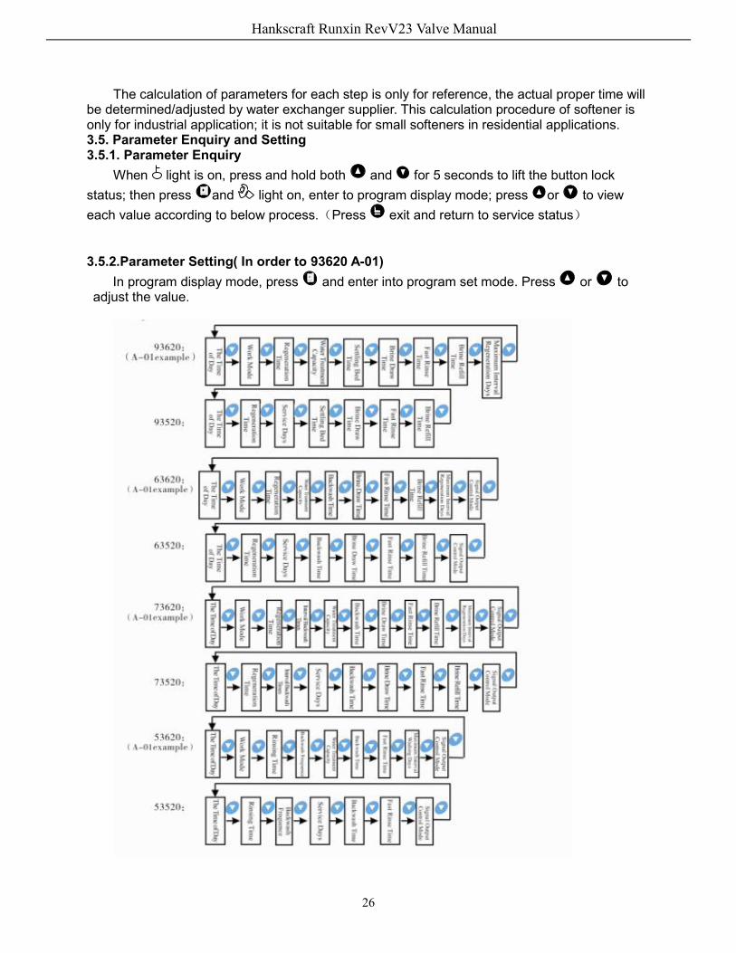
The calculation of parameters for each step is only for reference, the actual proper time will be determined/adjusted by water exchanger supplier. This calculation procedure of softener is only for industrial application; it is not suitable for small softeners in residential applications. 3.5. Parameter Enquiry and Setting 3.5.1. Parameter Enquiry
When light is on, press and hold both and for 5 seconds to lift the button lock status; then press and light on, enter to program display mode; press or to view each value according to below process.(Press exit and return to service status) 3.5.2.Parameter Setting( In order to 93620 A-01)
In program display mode, press and enter into program set mode. Press or to adjust the value.
Hankscraft Runxin RevV23 Valve Manual

27
3.5.3. The Steps of Parameter Setting Items Process steps Symbol
Time of Day
When time of day “12:12” continuously flashes; it is a reminder to reset the time of day; 1. Press to enter into program display mode; both and
symbol light on,“:” flashes; Press , both and hour value will flash, press or to adjust the hour value; 2. Press again, both and minute value flash, through
or to adjust the minute value; 3. Press a confirmation beep will sound, confirming the adjustment, press to return.
Control Mode
1. In control mode display status, press and enter into program set mode, both and 01 values will flash; 2. Press or ,set the value to be A-01, A-02, A-03 or A-04 control mode 3. Press a confirmation beep will sound, confirming the adjustment, press to return.
Regeneration Time
1. In regeneration time display status, press and enter into program set mode. Both and 02 will flash; Press or to adjust the hour value; 2. Press again, and 00 will flash, press or to adjust the minute value; 3. Press a confirmation beep will sound, confirming the adjustment, press to return.
Water Treatment Capacity
1. In water treatment capacity display status, it shows and 200.00. Press and enter into program set mode. Both and 200.00 will flash; 2. Press or to adjust the water treatment capacity value (m3); 3. Press a confirmation beep will sound, confirming the adjustment, press to return.
Settling bed Time
1. In Settling bed time display status,shows and 2-10:00. Press and enter into program set mode, both and 10 will flash; Press and , modify the Settling bed minute time; 2.Press and 00 will flash, press and , modify the Settling bed second time; 3. Press a confirmation beep will sound, confirming the adjustment, press to return.
Hankscraft Runxin RevV23 Valve Manual

28
Brine& Slow Rinse Time
1. In Brine & slow rinse time display status, it shows and 3-60:00. Press and enter into program set mode. Both and 60 will flash; Press and ,modify the Brine & slow rinse minute time; 2. Press and 00 will flash, press and ,modify the Brine & slow rinse second time; 3. Press a confirmation beep will sound, confirming the adjustment, press to return.
Fast Rinse Time
1. In Fast rinse time display status, it shows and 4-10:00. Press and enter into program set mode. Both and 10 will flash; Press and , modify the Fast rinse minute time; 2. Press and 00 flashes, press and , modify the Fast rinse second time; 3. Press a confirmation beep will sound, confirming the adjustment, press to return.
Brine Refill Time
1. In Brine refill time display status, it shows and 5-05:00. Press and enter into program set mode. Both and 05 will flash; Press and , modify the Brine refill minute time; 2. Press , and 00 flashes, press and , modify the Brine refill second time; 3. Press a confirmation beep will sound, confirming the adjustment, press to return.
Maximum Interval Regeneration Days
1. In maximum Interval regeneration days display status, it shows H-30. Press and enter into program set mode. Both and 30 will flash; 2. Press or to adjust the Interval regeneration days; 3. Press a confirmation beep will sound, confirming the adjustment, press to return.
For example, the fast rinse time of a softener is 12 minutes. After regenerating, the chlorides in the outlet water are always higher than normal, indicating that there is not enough time for fast rinse. If you want to increase the fast rinse time, the modification steps as follows: ① Press and hold both and to lift the button lock status ( light off); ② Press , and lights up; ③ Press or continuously until light on. Then the digital area shows: 4-12M; ④ Press , then press and 12 will flash; ⑤ Press continuously until 12 changes to 15; ⑥ Press , there will be a confirmation beep and the figure will stop flashing; the program back to enquiry status. ⑦ If you want to adjust other parameters, you can repeat the steps from ② to ⑤; if you don’t, press and quit from the inquiry status, the display will show the current service status.
Hankscraft Runxin RevV23 Valve Manual

29
3.6. Trial Running After installing the multi-functional flow control valve on the resin tank with the connected
pipes, and setting up the relevant parameters for the system, please conduct a trail run as follows: A. Close the inlet valve B & C, and open the bypass valve A. After cleaning the foreign materials in the pipe, close the bypass valve A. (as Figure 1-4 shows) B. Fill the brine tank with the planned amount of water and adjust the air check valve. Then add solid salt to the tank dissolving the salt as much as possible. C. Turn on power. Press and go in the Backwash position; when light is on (For floating bed, switch valve to Fast Rinse), slowly open the inlet valve B to 1/4 position, making the water flow into the resin tank; you should hear the sound of air-out from the drain pipeline. After all of the air is out of the pipeline, open inlet valve B completely to clean the foreign material out of the resin tank until the outlet water is clean. It will take 8~10 minutes to finish the whole process depending on media.
D. Press , advancing the position from Backwash to Brine & Slow Rinse; when light is on it indicates the valve is entering Brine & Slow Rinse. The air check valve closes when control valve finishes drawing brine; slow rinse starts. About 60~65 minute process. E. Press to get to Fast rinse position. light turns on. It takes about 10~15 minutes. Remove some outlet water for testing: if the water hardness reaches the desired requirement, and the chlorides in the water are almost the same level compared with the inlet water, then proceed to the next step. F. Press to Brine refill position. When the light is on it indicates the brine tank is being refilled with water to the required level. It takes about 5~6 minutes, then add solid salt to the brine tank. G. Press , this forces the control valve to advance to “In Service” status; light turns on and valve will start running. Note: When the control valve enters into the regeneration status, all programs can be finished automatically according to the setting time; if you want one of the steps to terminate early, press . If the water inflow is too fast, the media in tank will be damaged. When water inflow is too slow, there is a sound of air emptying from the drain pipeline. After changing resin, empty air that is in the resin according to the above Step C. In the process of trial running, ensure there are no leakages in any cycle. The time for Backwash, Brine & Slow Rinse, Brine Refill and Fast Rinse position can be set and executed according to the calculation in the formula or suggestions from the control valve suppliers.
Hankscraft Runxin RevV23 Valve Manual

30
3.7. Trouble-Shooting A. Control Valve Fault
Problem Cause Correction
1. Softener fails to regenerate.
A. Electrical service to unit has been interrupted. B. Regeneration cycles set incorrectly. C. Controller is defective. D. Motor fails to work.
A. Verify permanent electricity (Check fuse, plug, pull chain or switch). B. Reset regeneration cycles. C. Replace controller. D. Replace motor.
2. Regeneration time is not correct.
A. Time of Day is not set correctly. B. Power failure for more than 3 days.
Check program and reset time of day.
3. Softener yielding hard water.
A. Bypass valve is open or leaking. B. No salt in brine tank. C. Injector plugged. D. Insufficient water flowing into brine tank. E. Leak at O-ring on riser pipe. F. Internal valve leak. G. Regeneration cycles not correct. H. Shortage of resin. I. Bad quality of feed water or turbine blocked.
A. Close or repair bypass valve. B. Add salt to brine tank and maintain salt level above water level. C. Change or clean injector. D. Check brine tank refill time. E. Make sure riser pipe is not cracked. Check o-ring and tube pilot. F. Change valve body. G. Set correct regeneration cycles in the program. H. Add resin to mineral tank and check whether resin leaks. I. Reduce the inlet turbidity, clean or replace turbine.
4. Softener fails to draw brine.
A. Line pressure is too low. B. Brine line is plugged. C. Brine line is leaking. D. Injector is plugged. E. Internal control leak. F. Drain line is plugged. G. Sizes of injector and DLFC don’t match system size. H. Ball valve or cable failure
A. Increase line pressure. B. Clean brine line. C. Replace brine line. D. Clean or replace injector. E. Replace valve body. F. Clean drain line flow control. G. Select correct injector size and DLFC according to the P32 requirements. H. Replace ball valve or cable
5. Unit uses too much salt. A. Improper salt setting. B. Excessive water in brine tank.
A. Check salt usage and salt setting. B. See problem no.6.
6. Excessive water in brine tank.
A. Brine refill time set too long. B. Foreign material in brine line. C. Foreign material in brine valve / plugs drain line flow control. D. No overflow safety in brine tank / float assembly. E. Ball valve doesn’t close.
A. Reset correct brine refill time. B. Clean brine line. C. Clean brine valve and brine line. D. Stop water supply and reinstall float assembly in brine tank. E. Close or replace ball valve or cable.
7. Pressure lost or iron in outlet water.
A. Iron in the inlet pipe. B. Iron mass in the softener. C. Fouled resin bed. D. Too much iron in the raw water.
A. Clean the inlet pipe. B. Clean valve and add resin cleaning chemical, increase frequency of regeneration. C. Check backwash, brine draw and brine tank refill. Increase frequency of
Hankscraft Runxin RevV23 Valve Manual

31
regeneration and backwash time. D. Iron removal equipment is required to install before softening system.
8. Loss of mineral through drain line.
A. Air in water system. B. Bottom distributor basket damaged. C. Improperly sized drain line flow control.
A. Check that well system has proper air elimination. B. Replace bottom distributor basket. C. Check for proper drain rate.
9. Control cycles continuously.
A. Locating signal writing breakdown. B. Controller is faulty. C. Foreign material stuck the driving gear. D. Time of regeneration steps were set to zero.
A. Check and connect locating signal wiring. B. Replace controller. C. Remove foreign material. D. Check program setting and reset.
10. Drain flows continuously.
A. Internal valve leak. B. If there was a power outage during the backwash cycle.
A. Check and repair valve body or replace it. B. Adjust valve to service position or turn off bypass valve and restart.
11. Interrupted or irregular brine.
A. Water pressure too low or not stable. B. Injector is plugged or faulty. C. Air in resin tank. D. Material in resin tank during backwash.
A. Increase water pressure. B. Clean or replace injector. C. Check and find the reason. D. Remove the material in resin tank.
12. Water flows from drain or brine line after regeneration.
A. Foreign material in the valve; valve cannot close completely. B. Hard water mixed in valve body. C. Water pressure is too high which results in the valve not being in the right position. D. Ball valve or cable failure.
A. Clean foreign material in valve body. B. Change valve core or sealing ring. C. Reduce water pressure or use pressure release device. D. Replace ball valve or cable.
13. Salt water in softened water.
A. Foreign material in injector or injector fails to work. B. Brine valve cannot be shut-off. C. Time of rapid rinse too short.
A. Clean and repair injector. B. Repair brine valve or clean it. C. Extend rapid rinse time.
14. Unit capacity decreases.
A. Unit fails to regenerate or does not regenerate properly. B. Fouled resin bed. C. Salt setting incorrect. D. Softener setting incorrect. E. Reduced quality of raw water. F. Turbine of flow meter is stuck.
A. Regenerate according to the correct operation requirement. B. Increase backwash flow rate and time, clean or change resin. C. Readjust brine drawing time. D. Test outlet water, recount, and reset parameters. E. Manual regenerate the system temporarily, then reset regeneration cycle. F. Disassemble flow meter and clean it or replace turbine.
Hankscraft Runxin RevV23 Valve Manual

32
B. Controller Fault Problem Cause Correction
1. All indictors displayed on front panel.
A. Wiring of front panel failure. B. Control board is faulty. C. Transformer damaged. D. Electrical service not stable.
A. Check and replace the wiring. B. Replace control board. C. Check and replace transformer. D. Check and adjust electrical service.
2. No display on front panel.
A. Wiring of front panel failure. B. Front panel damaged. C. Control board damaged. D. Electricity is interrupted.
A. Check and replace wiring. B. Replace front panel. C. Replace control board. D. Check electricity.
3. E11 Flashes
A. Wiring of locating board failure. B. Locating board damaged. C. Mechanical driven failure. D. Faulty control board. E. Wiring of motor failure. F. Motor 1 damaged.
A. Replace wiring. B. Replace locating board. C. Check and repair mechanical part. D. Replace control board. E. Replace wiring. F. Replace motor 1.
4. E21 Flash
A. Wiring of locating board failure. B. Locating board damaged. C. Mechanical driven failure. D. Faulty control board. E. Wiring of motor failure. F. Motor 2 damaged.
A. Replace wiring. B. Replace locating board. C. Check and repair mechanical part. D. Replace control board. E. Replace wiring. F. Replace motor 2.
5. E12 or E22 Flashes
A. Hall component on locating board damaged. B. Wiring of locating board failure. C. Control board is faulty.
A. Replace locating board. B. Replace wiring. C. Replace control board.
6. E3 or E4 Flashes A. Control board is faulty. A. Replace control board.
Hankscraft Runxin RevV23 Valve Manual

33
3.8. Assembly & Parts RevV 23-B exploring drawing
Hankscraft Runxin RevV23 Valve Manual

34
RevV 23-B Assembly & Parts: Item No. Description Part No. Quantity Item No. Description Part No. Quantity
1 Hexagon Head Bolts M10×40 5851010 4 32 Control Board 6382049 1
2 Fixed Part 8109043 1 33 Dust Cover 8005037 1
3 Hexagon Head Bolts M10X16 8902046 3 34 Board Back Cover 5300003 1
4 Hexagon Nut 8940023 4 35 Cable Clip 8126001 1
5 Hexagon Head Bolts M10X35 5851001 2 36 Tree-core Spring 5517001 1
6 Fixed Part 8109073 1 37 Bushings 8126006 1
7 Fixed Part 8109060 1 38 Board Front Cover 8300013 1
8 Fixed Part 8109075 1 39 Label 8865011 1
9 Animated Connector 8947005 1 40 Display Board 6381007 1
10 Drain Line Flow Control 8468012 1 41 Screw, Cross
ST2.9X9.5 8909008 14
11 Seal Ring 8371008 1 42 Gear 5241017 1
12 Screw, Cross ST3.9X13 8909003 13 43 Screw, Cross
ST4.8X19 8909018 2
13 Injector 5468017 1 44 Gear 5241018 1
14 O-ring 52X3 8378096 1 45 Pin 2.5X12 8993004 2
15 Injector Cover 8315030 1 46 Locating Board 6380027 1
16 Hexagon Head Bolts M5×20 5851006 4 47 Locking Ring 8994009 2
17 Seal Ring 8371019 2 48 Small Gear 5241008 2
18 Electric Ball Valve 2976064 2 49 Button C4X12 8971001 2
19 Hexagonal Nut 8940002 4 50 Motor 6158038 1
20 Seal Ring 8370079 1 51 Motor 6158039 1
21 Fixed Disk 8469052 1 52 O-ring 59.92x3.53 8378110 4
22 Moving Disk 8459051 1 53 Shaft 8258027 1
23 Shaft 8258005 1 54 Fixed Disk 8459052 1
24 O-ring 123.19x5.33 8378161 4 55 Moving Disk 8469053 1
Hankscraft Runxin RevV23 Valve Manual
35
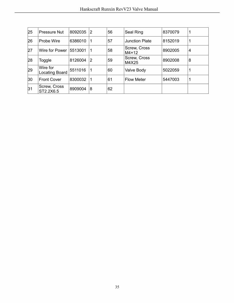
25 Pressure Nut 8092035 2 56 Seal Ring 8370079 1
26 Probe Wire 6386010 1 57 Junction Plate 8152019 1
27 Wire for Power 5513001 1 58 Screw, Cross M4×12 8902005 4
28 Toggle 8126004 2 59 Screw, Cross M4X25 8902008 8
29 Wire for Locating Board 5511016 1 60 Valve Body 5022059 1
30 Front Cover 8300032 1 61 Flow Meter 5447003 1
31 Screw, Cross ST2.2X6.5 8909004 8 62
Hankscraft Runxin RevV23 Valve Manual
landres
Typewritten Text

36
RevV 23-A exploring drawing:
Hankscraft Runxin RevV23 Valve Manual

37
RevV 23-A Assembly & Parts Item No. Description Part No. Quantity Item No. Description Part No. Quantity
1 Screw, Cross M4X25 8902008 8 32 Dust Cover 8005037 1
2 Screw, Cross M4×12 8902005 4 33 Cable Clip 8126001 1
3 Hexagon Head Bolts M10×40 8902046 4 34 Three-core
Spring 5517001 1
4 Screw, Cross M10X16 8902046 3 35 Bushings 8126006 1
5 Fixed Part 8109073 1 36 Board Front Cover 8300013 1
6 Fixed Part 8109043 1 37 Label 8865011 1
7 Fixed Part 8109060 1 38 Display Board 6381007 1
8 Hexagon Nut 8940023 4 39 Board Back Cover 5300003 1
9 Hexagon Head Bolts M10×35 5851001 2 40 Screw, Cross
ST2.9X9.5 8909008 14
10 Fixed Part 8109074 1 41 Screw, Cross ST4.8X19 8909018 2
11 Flow Meter 5447003 1 42 Gear 5241018 1
12 Motor 6158038 1 43 Gear 5241017 1
13 Motor 6158039 1 44 Pin 2.5X12 8993004 2
14 Button C4X12 8971001 2 45 Locating Board 6380027 1
15 Small Gear 5241008 2 46 O-ring 59.92x3.53 8378110 4
16 Locking Ring 8994009 1 47 Locking Ring 8258005 1
17 Hexagon Nut 8940002 4 48 Moving Disk 8459051 1
18 Junction Plate 8152019 1 49 Fixed Disk 8469051 1
19 Seal Ring 8370079 1 50 Seal Ring 8370078 1
20 Fixed Disk 8469052 1 51 Screw, Cross ST3.9x19 8909003 13
21 Moving Disk 8459052 1 52 Animated Connector 8947005 1
22 Shaft 81258027 1 53 Drain Line Flow Control 8468049 1
23 O-ring 123.19x5.33 8378161 4 54 Seal Ring 8371008 1
24 Pressure Nut 8092035 2 55 Valve Body 5022058 1
5022059
Hankscraft Runxin RevV23 Valve Manual

38
25 Probe Wire 6386010 1 56 Injector 5468020 1
26 Wire for Power 5513001 1 57 O-ring 52x3 8378096 1
27 Toggle 8126004 2 58 Injector Cover 8315007 1
28 Wire for Locating Board 5511016 1 59 Hexagon Bead
Bolts M5×20 5851006 4
29 Front Cover 8300032 1 60 Seal Ring 8371019 1
30 Screw, Cross ST2.2X6.5 8909004 8 61 Electric Ball
Valve 2976064 1
31 Control Board 6382049 1 5447003 Flow meter:
5447003 Flow Meter Components:
Item No. Description Part No. Quantity
Item No. Description Part No. Quantity
1 Animated Connector 8947004 1 5 O-ring 60X4 8378137 1 2 Seal Ring 8371008 1 6 Turbine 5436005 1 3 Connector 8458016 1 7 Rotator 8211003 1 4 Fixed Connector 8109006 1 8 Flow Meter Shell 8002702 1
Hankscraft Runxin RevV23 Valve Manual
39
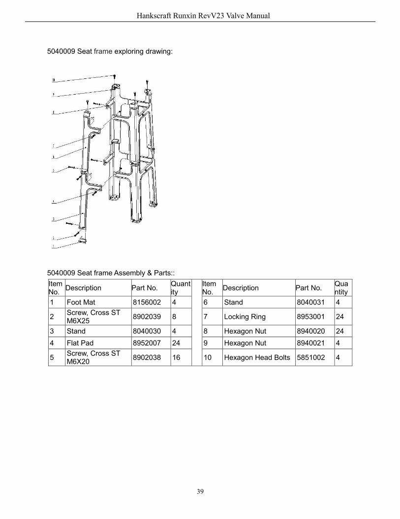
5040009 Seat frame exploring drawing:
5040009 Seat frame Assembly & Parts::
Item No. Description Part No. Quant
ity Item
No. Description Part No. Quantity
1 Foot Mat 8156002 4 6 Stand 8040031 4
2 Screw, Cross ST M6X25 8902039 8 7 Locking Ring 8953001 24
3 Stand 8040030 4 8 Hexagon Nut 8940020 24 4 Flat Pad 8952007 24 9 Hexagon Nut 8940021 4
5 Screw, Cross ST M6X20 8902038 16 10 Hexagon Head Bolts 5851002 4
Hankscraft Runxin RevV23 Valve Manual